EP1320140A1 - Fuel cell - Google Patents
Fuel cell Download PDFInfo
- Publication number
- EP1320140A1 EP1320140A1 EP01956853A EP01956853A EP1320140A1 EP 1320140 A1 EP1320140 A1 EP 1320140A1 EP 01956853 A EP01956853 A EP 01956853A EP 01956853 A EP01956853 A EP 01956853A EP 1320140 A1 EP1320140 A1 EP 1320140A1
- Authority
- EP
- European Patent Office
- Prior art keywords
- fuel cell
- polymer electrolyte
- catalyst
- particles
- gas
- Prior art date
- Legal status (The legal status is an assumption and is not a legal conclusion. Google has not performed a legal analysis and makes no representation as to the accuracy of the status listed.)
- Withdrawn
Links
Images


Classifications
-
- H—ELECTRICITY
- H01—ELECTRIC ELEMENTS
- H01M—PROCESSES OR MEANS, e.g. BATTERIES, FOR THE DIRECT CONVERSION OF CHEMICAL ENERGY INTO ELECTRICAL ENERGY
- H01M4/00—Electrodes
- H01M4/86—Inert electrodes with catalytic activity, e.g. for fuel cells
-
- H—ELECTRICITY
- H01—ELECTRIC ELEMENTS
- H01M—PROCESSES OR MEANS, e.g. BATTERIES, FOR THE DIRECT CONVERSION OF CHEMICAL ENERGY INTO ELECTRICAL ENERGY
- H01M4/00—Electrodes
- H01M4/86—Inert electrodes with catalytic activity, e.g. for fuel cells
- H01M4/8605—Porous electrodes
-
- H—ELECTRICITY
- H01—ELECTRIC ELEMENTS
- H01M—PROCESSES OR MEANS, e.g. BATTERIES, FOR THE DIRECT CONVERSION OF CHEMICAL ENERGY INTO ELECTRICAL ENERGY
- H01M4/00—Electrodes
- H01M4/86—Inert electrodes with catalytic activity, e.g. for fuel cells
- H01M4/90—Selection of catalytic material
- H01M4/92—Metals of platinum group
- H01M4/925—Metals of platinum group supported on carriers, e.g. powder carriers
- H01M4/926—Metals of platinum group supported on carriers, e.g. powder carriers on carbon or graphite
-
- H—ELECTRICITY
- H01—ELECTRIC ELEMENTS
- H01M—PROCESSES OR MEANS, e.g. BATTERIES, FOR THE DIRECT CONVERSION OF CHEMICAL ENERGY INTO ELECTRICAL ENERGY
- H01M4/00—Electrodes
- H01M4/86—Inert electrodes with catalytic activity, e.g. for fuel cells
- H01M4/88—Processes of manufacture
- H01M4/8803—Supports for the deposition of the catalytic active composition
- H01M4/881—Electrolytic membranes
-
- H—ELECTRICITY
- H01—ELECTRIC ELEMENTS
- H01M—PROCESSES OR MEANS, e.g. BATTERIES, FOR THE DIRECT CONVERSION OF CHEMICAL ENERGY INTO ELECTRICAL ENERGY
- H01M8/00—Fuel cells; Manufacture thereof
- H01M8/02—Details
- H01M8/0271—Sealing or supporting means around electrodes, matrices or membranes
-
- H—ELECTRICITY
- H01—ELECTRIC ELEMENTS
- H01M—PROCESSES OR MEANS, e.g. BATTERIES, FOR THE DIRECT CONVERSION OF CHEMICAL ENERGY INTO ELECTRICAL ENERGY
- H01M8/00—Fuel cells; Manufacture thereof
- H01M8/10—Fuel cells with solid electrolytes
- H01M8/1004—Fuel cells with solid electrolytes characterised by membrane-electrode assemblies [MEA]
-
- H—ELECTRICITY
- H01—ELECTRIC ELEMENTS
- H01M—PROCESSES OR MEANS, e.g. BATTERIES, FOR THE DIRECT CONVERSION OF CHEMICAL ENERGY INTO ELECTRICAL ENERGY
- H01M8/00—Fuel cells; Manufacture thereof
- H01M8/10—Fuel cells with solid electrolytes
- H01M8/1016—Fuel cells with solid electrolytes characterised by the electrolyte material
- H01M8/1018—Polymeric electrolyte materials
- H01M8/102—Polymeric electrolyte materials characterised by the chemical structure of the main chain of the ion-conducting polymer
- H01M8/1023—Polymeric electrolyte materials characterised by the chemical structure of the main chain of the ion-conducting polymer having only carbon, e.g. polyarylenes, polystyrenes or polybutadiene-styrenes
-
- H—ELECTRICITY
- H01—ELECTRIC ELEMENTS
- H01M—PROCESSES OR MEANS, e.g. BATTERIES, FOR THE DIRECT CONVERSION OF CHEMICAL ENERGY INTO ELECTRICAL ENERGY
- H01M8/00—Fuel cells; Manufacture thereof
- H01M8/10—Fuel cells with solid electrolytes
- H01M8/1016—Fuel cells with solid electrolytes characterised by the electrolyte material
- H01M8/1018—Polymeric electrolyte materials
- H01M8/1039—Polymeric electrolyte materials halogenated, e.g. sulfonated polyvinylidene fluorides
-
- Y—GENERAL TAGGING OF NEW TECHNOLOGICAL DEVELOPMENTS; GENERAL TAGGING OF CROSS-SECTIONAL TECHNOLOGIES SPANNING OVER SEVERAL SECTIONS OF THE IPC; TECHNICAL SUBJECTS COVERED BY FORMER USPC CROSS-REFERENCE ART COLLECTIONS [XRACs] AND DIGESTS
- Y02—TECHNOLOGIES OR APPLICATIONS FOR MITIGATION OR ADAPTATION AGAINST CLIMATE CHANGE
- Y02E—REDUCTION OF GREENHOUSE GAS [GHG] EMISSIONS, RELATED TO ENERGY GENERATION, TRANSMISSION OR DISTRIBUTION
- Y02E60/00—Enabling technologies; Technologies with a potential or indirect contribution to GHG emissions mitigation
- Y02E60/30—Hydrogen technology
- Y02E60/50—Fuel cells
Definitions
- the present invention relates to a fuel cell. More particularly, the present invention relates to a catalyst layer in an electrode which is a constituent element of a fuel cell.
- Fuel cells using polymer electrolytes generate electric power and heat simultaneously by electrochemically reacting a fuel gas containing hydrogen with an oxidant gas containing oxygen such air and the like.
- Fig. 1 shows a schematic sectional view of an electrode membrane assembly (MEA) constituting a polymer electrolyte type fuel cell.
- MEA electrode membrane assembly
- a catalyst layer 12 is formed on both surfaces of a polymer electrolyte membrane 11 transporting a hydrogen ion selectively.
- This catalyst layer 12 is formed of a mixture obtained by mixing a carbon powder carrying a platinum-type metal catalyst with a hydrogen ion conductive polymer electrolyte.
- a gas diffusion layer 13 having fuel gas permeability and electron conductivity is formed.
- this gas diffusion layer 13 for example, water-repellent treatment-performed carbon paper is used.
- This catalyst layer 12 and the gas diffusion layer 13 constitute an electrode 14.
- sealing materials are placed such as gaskets sandwiching a polymer electrolyte membrane, around the electrode 14. This sealing material is previously integrated with the electrode 14 and the polymer electrolyte membrane 11.
- the electrode 14 and the polymer electrolyte membrane 11 constitute MEA 15.
- Fig. 2 shows a schematic sectional view of a unit cell using MEA 15 shown in Fig. 1.
- electroconductive separator plates 21 are placed for fixing this mechanically.
- gas passages 22 for feeding a gas to the electrode 14 and removing out a produced gas and excess gases.
- the gas passages 22 can be placed also as separate members on the separator plate 21, but it is general to form grooves on the surface of the separator 21, to form gas passages 22.
- unit cells 23 are used connected in series to be used.
- gas passages 22 are formd on rear and front, both surfaces of the separator plate 21, and separator plates and MEAs are repeatedly laminated in the order of separator plate/MEA/separator plate/MEA, and unit cells 23 are connected in series.
- piping for feeding a gas is branched into the number corresponding to the number of separator plates 21 to be used, and ends of the branched piping are allowed to communicate directly with the gas passages 22 of the separator plate 21.
- This jig is called a manifold, and a manifold communicating gas feeding piping directly with a separator plate is called an outer manifold.
- manifolds include an inner manifold having a simpler structure. In the case of the inner manifold, a penetration aperture is provided in a separator plate having gas passages formed, and the outlet and the inlet of the gas passage are connected to this aperture, and a gas is directly fed into this aperture.
- a cooling part through which cooling water is passed is inserted between separator plates, every one to three unit cells.
- the cooling part may have the same structure as that of the separator plate.
- a passage for cooling water is provided on the rear surface of the above-mentioned separator plate (surface not contacting with a gas diffusion layer) to form a cooling part in many cases.
- FIG. 3 A plan view schematically showing the structure of the surface of the above-mentioned separator plate 21 is shown in Fig. 3, and a plan view schematically showing the structure of the rear surface of the separator plate is shown in Fig. 4.
- a passage for a fuel gas or an oxidant gas is formed on the surface of the separator plate 21, and as shown in Fig. 4, a passage for circulating cooling water is formed on the rear surface of the separator plate 21.
- a fuel gas is charged from an aperture 31a, and discharged from an aperture 31b.
- an oxidant gas is injected from an aperture 32a, and discharged from an aperture 32b.
- Cooling water is injected from an aperture 33a, and cooling water is discharged from an aperture 33b.
- a fuel gas injected from an aperture 31a is introduced to an aperture 31b through a convex part 34 constituting a gas passage, meandering on the way.
- a convex part 35 constitutes a gas passage together with the concave part 34.
- the separator plate used in such a polymer electrolyte type fuel cell should have high electric conductivity and gas tightness against a fuel gas, further, should have a high corrosion resistance against an oxidation-reduction reaction between hydrogen and oxygen, namely, an acid resistance.
- conventional separators are produced by forming a gas passage by performing cutting process on the surface of a plate made of glassy carbon, or filling a press molding die on which a gas passage has been formed with a mixture of a binder and an expanded graphite powder, performing pressing process, then, effecting sintering by heating, and the like.
- dissolved metal ions diffuse in a polymer electrolyte and trapped at an ion exchange site in the polymer electrolyte, leading to decrease in ion conductivity of the polymer electrolyte itself resultantly. Namely, the polymer electrolyte itself deteriorates. For avoiding such a deterioration, it is general to plate the surface of a metal plate with gold having a certain thickness. Further, it has also been investigated to produce a separator plate with a electroconductive resin composition obtained by mixing an epoxy resin and a metal powder.
- MEA, separator plate and cooling part as described above are laminated alternately to obtain a laminate composed of 10 to 200 unit cells laminated, and this laminate is sandwiched with end plates via a collecting plate and an insulating plate. Then, the end plates, collecting plates, insulating plates and laminate are fixed by a fastening volt, to obtain a fuel cell stack.
- Fig. 5 is a schematic perspective view of the fuel cell stack referred to here.
- a necessary number of unit cells 41 are laminated to constitute a laminate, and the laminate is sandwiched between two end plates 42 and fastened with a plurality of fastening volts 43.
- the collecting plate and the insulating plate are abbreviated.
- an aperture 44a for charging an oxidant gas, an aperture 45a for charging a fuel gas and an aperture 46a for charging cooling water are provided on the end plate 42.
- an aperture 44b for discharging an oxidant gas, an aperture 45b for discharging a fuel gas and an aperture 46b for discharging cooling water are also provided.
- the size of the area of so-called three- phase interface formed of a fine pore serving as a feeding passage for a reaction gas, a hydrogen ion conductive polymer electrolyte, and a catalyst material which is an electron conductor affects the discharging ability of the cell.
- a noble metal which is a catalyst material trials have been effected for mixing a hydrogen ion conductive polymer electrolyte with the catalyst material and dispersing it.
- 62-61118 and 62-61119 have suggested a method in which a mixture of a dispersion or solution of a polymer electrolyte with a catalyst material is applied on a polymer electrolyte membrane, this polymer electrolyte membrane and an electrode material are together hot-pressed and, then, the catalyst material is reduced.
- Japanese Patent Publication No. 2-48632 has suggested a method in which a dispersion or solution of an ion exchange membrane resin is sprayed on a porous electrode obtained by molding, and this electrode and ion exchange membrane are hot-pressed.
- Japanese Laid-Open Patent Publication No. 3-184266 has suggested a method in which a powder prepared by coating the surface of a polymer resin with a polymer electrolyte is mixed in an electrode
- Japanese Laid-Open Patent Publication No. 3-295172 has suggested a method in which a powder of a polymer electrolyte is mixed in an electrode.
- Japanese Laid-Open Patent Publication No. 5-36418 has suggested a method in which a polymer electrolyte, a catalyst, a carbon powder and a fluorocarbon resin are mixed, the obtained mixture is molded in the form of membrane to obtain an electrode.
- US Patent No. 5211984 has suggested a method in which a polymer electrolyte, a catalyst and a carbon powder are dispersed in the form of ink into a solvent glycerin or tetrabutylammonium salt, to prepare a dispersion, a membrane made of the obtained dispersion is molded on a polytetrafluoroethylene (PTFE) film, then, the obtained membrane is transferred onto the surface of a solid polymer electrolyte membrane.
- PTFE polytetrafluoroethylene
- an object of the present invention is to clarify a relation between a hydrogen ion conductive polymer electrolyte, catalyst particle and a carbon powder in a catalyst layer of an electrode of a fuel cell, and to provide a fuel cell excellent in a power generation property.
- an electrode reaction of a fuel cell is controlled by diffusion, in a relatively higher current density region of current density of 0.1 A/cm 2 or more.
- gas diffusing rate controls the rate of an electrode reaction. Therefore, for improving the performance of a cell, it is necessary to improve gas diffusing efficiency.
- the catalyst layer is made porous as much as possible by mixing a pore forming agent in producing a catalyst layer to obtain the layer through molding and, after the molding, removing the pore forming agent. Specifically, a porosity of 70% or more is secured, usually.
- a porosity of 70% or more is secured, usually.
- the thickness of a catalyst layer should be increased relatively.
- the utilization efficiency of a catalyst lowers in portions remote far from a polymer electrolyte membrane in a catalyst layer as compared with portions adjacent to a polymer electrolyte membrane.
- the thickness of a catalyst layer becomes larger, the cell performance is improved further, however, improvement in the cell performance is gradually saturated. However, sufficient cell performance is not obtained unless the thickness of a catalyst layer is so increased.
- an electroconductive gas diffusion layer is generally used also as a gas diffusion layer.
- the gas diffusion layer compensates insufficient electric collection of the catalyst layer and diffuses a gas, and additionally, exhibits an effect of facilitating discharge of excess water generated in the catalyst layer by a cell reaction. Therefore, from the standpoint of gas diffusing efficiency, a thinner gas diffusion layer is believed to be more effective.
- larger surface area of parts holding water of a gas diffusion layer is more effective, therefore, when the thickness of a gas diffusion layer is larger, evaporation of water can be effectively facilitated.
- pressure loss of a feeding gas increases, and when an efficiency of the whole fuel cell power generation system is taken into consideration, auxiliary mobility increases and the system efficiency decreases, problematically.
- another object of the present invention is to provide optimum MEA capable of producing a fuel cell having an excellent power generation performance and a fuel cell power generation system having an excellent system efficiency.
- the present invention relates to a catalyst layer and a gas diffusion layer particularly constituting MEA, and a water repellent layer which can be formed between them.
- the gas diffusion layer has mainly the following three functions.
- the first function is a function of diffusing a reaction gas such as a fuel gas or oxidant gas so as to uniformly feed the reaction gas from a gas passage formed on a further outer surface of the gas diffusion layer to the catalyst in the catalyst layer.
- the second function is a function of quickly discharging water produced by a reaction in a catalyst layer, into a gas passage.
- the third function is a function of conducting electrons necessary for a reaction or generated electrons. Namely, the gas diffusion layer is required to have high reaction gas permeability, water vapor permeability and electron conductivity.
- the gas diffusion layer having a porous structure is obtained by using a carbon fine powder having a developed structure, a pore forming agent, and an electroconductive porous substrate such as carbon paper or carbon cloth, for imparting gas permeability to the gas diffusion layer.
- a carbon fine powder having a developed structure a carbon fine powder having a developed structure
- a pore forming agent such as carbon paper or carbon cloth
- an electroconductive porous substrate such as carbon paper or carbon cloth
- the catalyst layer has mainly the following four functions.
- the first function is a function of feeding a reaction gas such as a fuel gas or oxidant gas fed from the gas diffusion layer to a reaction site of the catalyst layer.
- the second function is a function of quickly transferring hydrogen ions necessary for a reaction on the catalyst or produced hydrogen ions, to an electrolyte membrane.
- the third function is a function of transferring electrons necessary for a reaction or generated electrons.
- the fourth function is a high catalyst ability for quick reaction and the wide reaction area thereof. Namely, the catalyst layer is required to have high reaction gas permeability, hydrogen ion permeability, electron conductivity and catalyst ability.
- the catalyst layer having a porous structure is obtained by using a carbon fine powder having a developed structure and a pore forming agent, for imparting gas permeability to the catalyst layer. Further, for imparting hydrogen ion permeability to the catalyst layer, a polymer electrolyte is dispersed in portions around a catalyst in the catalyst layer, and a hydrogen ion network is formed. For impacting electron conductivity to the catalyst layer, an electron conductive material such as a carbon fine powder or a carbon fiber is used as a catalyst carrier.
- a metal catalyst having high reaction activity typified by platinum is prepared to have a particle size of several nm, this very fine particle is carried on a carbon fine powder, and the obtained catalyst carrying particles are dispersed in the catalyst layer.
- the carbon fine powder is a black powder of amorphous carbon having a diameter of 3 to 500 nm, not easily wetted with water, and has a specific gravity of 1.8 to 1.9 and an apparent specific gravity of 0.35 to 0.4 in terms of particle and 0.04 to 0.08 in terms of powder.
- the carbon fine powder can be produced by thermally decomposing hydrocarbons, extremely various products are obtained depending on differences in production methods, production conditions and the like. In any method, a raw material hydrocarbon is carbonized at a high temperature of 800°C or higher for a short period of time such as several milliseconds.
- crystallites having a disorderly layered structure which comprises a several layers of aromatic plane molecules having an average size of 10 to 30 ⁇ , aggregate complicatedly to constitute spherical particles. These spherical particles further bond to constitute an aggregate (structure) in the form of chain.
- the microscopic condition of the surface of this carbon fine powder differs from the condition of a simple fine particle of carbon, and an acidic functional group and other functional group are present on the surface of the particle, therefore, it has special industrial applications such as a rubber reinforcing agent.
- the hydrocarbons used for a raw material include natural gas, coal gas, acetylene gas, petroleum-based heavy oil, petroleum, creosote oil, naphthalene, anthracene and the like, and classified into gas black, oil black, acethylene black and the like depending on the raw material.
- the carbon fine powder are used as various rubber reinforcing agents (about 80% of them are for tires), and widely used for plastic reinforcing fillers, printing inks, paints, electric wires, electric columns and dry batteries, as well as carbon paper, Japanese ink, pigments, pencils, crayons, catalyst carriers, fireworks and thawing agents and the like.
- the main method of producing the carbon fine powder is as described below.
- the currently dominant furnace method was developed in U.S. during The World War II, and gases were used as a raw material at first, however, recently oils are used, and those of high quality are obtained at high yield.
- a raw material and air are blown into a furnace (burning furnace), the raw material is incompletely burnt continuously under turbulent diffusion, a burnt gas passed through a cooler is collected in a bag filter in the form of bag and is granulated.
- the furnace temperature is about 1600°C
- the burnt products are hydrogen, carbon monoxide, carbon dioxide, water vapor and carbon black (furnace black). Cooling is conducted by spraying water, and first, the primary cooling temperature is controlled at 900°C and the second cooling temperature is controlled at 400°C.
- a reason for increase in wetting property of such a carbon fine powder is believed in that since a conventionally used carbon fine powder is insufficiently graphitized, various functional groups are present on the surface, surface energy for water is high, and contact angle is small and, consequently, moisture absorption proceeds gradually.
- Still another object of the present invention is to solve the above-mentioned conventional problems, and to provide an electrode for fuel cell exhibiting higher performance by optimizing the water repellency of a carbon fine particle in a catalyst layer and a gas diffusion layer, and a polymer electrolyte type fuel cell and a liquid fuel cell using this electrode.
- the catalyst layer contains electroconductive carbon particles having a particle size of the primary particle of 10 nm or more and 150 nm or less, a hydrogen ion conductive polymer electrolyte and platinum, and has a thickness of 3 ⁇ m or more and 10 ⁇ m or less.
- the electrode has a water repellent layer between the catalyst layer and the gas diffusion layer, the water repellent layer contains electroconductive carbon particles having a particle size of the primary particle of 10 nm or more and 150 nm or less and a water repellent agent, portions of the water repellent layer not intruding into the gas diffusion layer have an average thickness of 5 ⁇ m or more and 50 ⁇ m or less.
- the average thickness of the gas diffusion layer is 250 ⁇ m or more and 400 ⁇ m or less.
- the catalyst layer has a porosity of 30% or more and 70% or less
- the water repellent layer has a porosity of 30% or more and 60% or less.
- the fuel cell has a sealing material on the peripheral parts of the electrode, and the distance between the electrode and the above-mentioned sealing material is 10 ⁇ m or more and 1 mm or less.
- the hydrogen ion conductive polymer electrolyte has a main chain skeleton comprised of fluorocarbon and a side chain having an end group comprised of sulfonic acid or alkylsulfonic acid, and has an equivalent weight of 80 g/Eq or more and 110 g/Eq or less.
- the electroconductive carbon particles have a specific surface area of 50 m 2 /g or more and 1500 m 2 /g or less.
- the electroconductive carbon particles contain a graphitized carbon powder in an amount of 33% by weight or more.
- the lattice plane spacing d 002 of the (002) plane in the crystal structure of the above-mentioned graphitized carbon powder is 3.35 ⁇ or more and 3.44 ⁇ or less.
- the graphitized carbon powder is one obtained by thermally treating a carbon powder at 2000°C or more.
- the electroconductive carbon particles have a specific surface area of 58 m 2 /g or more and 1500 m 2 /g or less, and the catalyst particles are carried only on the outside of the electroconductive carbon particles.
- an end cation part composed of a polar functional group present on the outer surface of the electroconductive carbon particle is substituted by a catalyst cation.
- the catalyst particles have a specific surface area of 50 m 2 /g or more and 250 m 2 /g or less.
- the catalyst layer contains electroconductive carbon particles having a particle size of the primary particle of 10 nm or more and 150 nm or less, a hydrogen ion conductive polymer electrolyte and platinum, and has a thickness of 3 ⁇ m or more and 10 ⁇ m or less.
- the electrode has a water repellent layer between the catalyst layer and the gas diffusion layer, the water repellent layer contains electroconductive carbon particles having a particle size of the primary particle of 10 nm or more and 150 nm or less and a water repellent agent, portions of the water repellent layer not intruding into the gas diffusion layer have an average thickness of 5 ⁇ m or more and 50 ⁇ m or less.
- the average thickness of the gas diffusion layer is 250 ⁇ m or more and 400 ⁇ m or less.
- the catalyst layer has a porosity of 30% or more and 70% or less
- the water repellent layer has a porosity of 30% or more and 60% or less.
- the fuel cell has a sealing material on the peripheral parts of the electrode, and the distance between the electrode and the sealing material is 10 ⁇ m or more and 1 mm or less.
- the hydrogen ion conductive polymer electrolyte has a main chain skeleton comprised of fluorocarbon and a side chain having an end group comprised of sulfonic acid or alkylsulfonic acid, and has an equivalent weight of 80 g/Eq or more and 1100 g/Eq or less.
- the "equivalent weight” means the weight of the whole electrolyte giving 1 mol of sulfone group.
- the electroconductive carbon particles have a specific surface area of 50 m 2 /g or more and 1500 m 2 /g or less.
- the electroconductive carbon particles contain a graphitized carbon powder in an amount of 33% by weight or more.
- the lattice plane spacing d 002 of the (002) plane in the crystal structure of the graphitized carbon powder is 3.35 ⁇ or more and 3.44 ⁇ or less.
- the graphitized carbon powder is obtained by thermally treating a carbon powder at 2000°C or more.
- the electroconductive carbon particles have a specific surface area of 58 m 2 /g or more and 1500 m 2 /g or less, and the catalyst particles are carried only on the outside of the electroconductive carbon particles.
- the catalyst particles have a specific surface area of 50 m 2 /g or more and 250 m 2 /g or less.
- MEA was produced according to the following method.
- a dispersion of polytetrafluoroethylene (Lubron LDW-40 manufactured by Daikin Industries, Ltd.) was mixed in an amount of 30% by weight by dry weight with an electroconductive carbon particle powder (Denka Black manufactured by Denki Kagaku Kogyo K.K.), to produce a water repellent layer ink.
- the water repellent layer ink was applied on the surface of carbon paper (manufactured by Toray Industries, Inc.: TGPH060H), and heated at 350°C by a hot air dryer, to form a gas diffusion layer.
- platinum particles having an average particle size of about 30 ⁇ were carried on electroconductive carbon particles having a specific surface area of 70 m 2 /g (Denka Black manufactured by Denki Kagaku Kogyo K.K.), to obtain catalyst carrying particles. 25% by weight of the catalyst carrying particles were platinum particles.
- the catalyst carrying particles and a dispersion or solution of a hydrogen ion conductive polymer electrolyte were mixed to obtain a catalyst paste.
- the catalyst carrying particles and the hydrogen ion conductive polymer electrolyte were mixed so that the weight ratio represented by polymer electrolyte/electroconductive carbon particles was 0.2 to 2.0.
- As the hydrogen ion conductive polymer electrolyte a perfluorocarbonsulfonic acid having an equivalent weight of 1000 to 1100 g/Eq was used.
- the catalyst paste was printed on one surface of the gas diffusion layer and on both surfaces of a hydrogen ion conductive polymer electrolyte membrane (Nafion 112 manufactured by E. I. Du Pont de Nemours and Company, U.S.).
- the gas diffusion layer on the fuel electrode side and the gas diffusion layer on the air electrode side were laminated so that the catalyst paste surfaces faced while mutually sandwiching the hydrogen ion conductive polymer electrolyte membrane at the center, and these were connected by a hot press method.
- MEA membrane electrode assembly
- a gasket plate made of butyl rubber was connected to the outer peripheral parts of the polymer electrolyte membrane of the MEA, and manifold apertures for passing cooling water, fuel gas and oxidant gas were formed on the gasket plate.
- separator plates constituted of a resin impregnated graphite plate with a dimension of 20cm ⁇ 32cm ⁇ 1.3mm and having gas passages and cooling water passages of a depth of 0.5 mm were prepared.
- a separator plate having oxidant gas passages formed was laminated, and on another surface of MEA, a separator plate containing fuel gas passages formed was laminated, to obtain a unit cell.
- Two of this unit cell were laminated, then, this two cell-laminated cell was sandwiched by the separator plates having cooling passages formed. A plurality of this two unit cell laminate were laminated, to produce a cell stack containing 100 unit cells.
- a collecting plate made of stainless steel, an insulating plate made of an electrically insulating material and an end plate were fixed by a fastening rod.
- the fastening pressure under this condition was 10 kgf/cm 2 per area of the separator plate.
- a pure hydrogen gas was fed to the fuel electrode and air was fed to the air electrode, of thus produced polymer electrolyte fuel cell in this example.
- a fuel gas utilization (U f ) of 70% and an air utilization (U o ) of 40% the cell property of the above-mentioned cell stack was evaluated.
- the fuel gas was passed through hot water of 75°C for humidification, and air was passed through hot water of 50°C for humidification.
- Fig. 6 shows the output voltage when the current density was 700 mA/cm 2 .
- Fig. 6 is a graph showing the relation between the ratio of polymer electrolyte/electroconductive carbon particles and the output voltage per unit cell.
- Example 1 platinum was carried on electroconductive carbon particles having a specific surface of 70 m 2 /g, next, electroconductive carbon particles having a specific surface of 250 m 2 /g (Vulcan XC manufactured by Cabot) were used. A cell was produced in the same constitution as in Example 1 excepting the above-mentioned electroconductive carbon particle, and tested in the same conditions as in Example 1. The results are shown in Fig. 7.
- Example 2 Though 25 wt% of platinum was carried on electroconductive carbon particles having a specific surface area of 800 m 2 /g in Example 1, 50 wt% of platinum was carried in this example. Namely, 50 wt% of catalyst carrying particles were platinum particles.
- a cell was produced in the same constitution as in Example 1 excepting the above-mentioned electroconductive carbon particle, and tested in the same conditions as in Example 1. The results are shown in Fig. 10.
- a catalyst paste was prepared using a perfluorocarbonsulfonic acid having an equivalent weight of 800 to 850 g/Eq.
- a cell was produced in the same constitution as in Example 6 excepting the above-mentioned condition, and tested in the same conditions as in Example 1. The results are shown in Fig. 12.
- Fig. 13 shows the relation between the weight ratio of polymer electrolyte/electroconductive carbon particles and the specific surface area of electroconductive carbon particles, at which the output voltage is most excellent, in Figs. 6 to 12.
- Electroconductive carbon particles having a particle size of the primary particle of 10 nm or more and 150 nm or less were allowed to carry platinum particles having an average particle size of 30 ⁇ to obtain catalyst carrying particles for an air electrode (containing 50 wt% of platinum particles). Further, the carbon black was allowed to carry platinum-ruthenium alloy particles having an average particle size of 30 ⁇ to obtain catalyst carrying particles for a fuel electrode (containing 50 wt% of platinum-ruthenium alloy particles).
- a perfluorosulfonic acid of a chemical formula shown in the formula (2) was used as the hydrogen ion conductive polymer electrolyte.
- an ethanol dispersion or solution containing 9 wt% of a hydrogen ion conductive polymer electrolyte was cast on a smooth glass substrate, and dried to obtain a hydrogen ion conductive polymer electrolyte membrane having an average membrane thickness of 30 ⁇ m.
- the electrode ink and the pore forming agent-containing electrode ink were printed by a screen printing method, to obtain a polymer electrolyte membrane with catalyst layer.
- Carbon paper was used as the gas diffusion layer, and water repellent treatment was performed on this.
- Carbon non-woven fabric TGP-H-120 manufactured by Toray Industries, Inc.
- a fluorocarbon resin Neofron ND1 manufactured by Daikin Industries, Ltd.
- electroconductive carbon particles having a particle size of the primary particle of 10 nm or more and 150 nm or less and an aqueous dispersion of a PTFE powder were mixed, to prepare a water repellent layer ink.
- the water repellent layer ink was applied by a screen printing method to form a water repellent layer on one surface of the carbon non-woven fabric which was a gas diffusion layer.
- a part of the water repellent layer was intruded into, namely, buried into the carbon non-woven fabric, and by controlling the viscosity of the water repellent layer ink, the thickness of parts of the water repellent layer not intruded into the diffusion layer was controlled.
- MEA membrane/electrode assembly
- This MEA was thermally treated for 1 hour in a saturated water vapor atmosphere of 120°C, to allow conducting passages to develop sufficiently.
- a hydrogen ion conductive polymer electrolyte of the formula (2) is thermally treated under a wet atmosphere of a relatively high temperature of about 100°C of more, a hydrophilic channel as a hydrogen ion conductive passage is developed, to form a reverse micelle structure.
- an electrode of 16cm ⁇ 20cm was connected on both surfaces of a hydrogen ion conductive polymer electrolyte membrane of 20 cm ⁇ 32 cm, to obtain MEA containing electroconductive carbon particles carrying a catalyst for electrode reaction.
- a gasket plate made of rubber was connected to the outer peripheral parts of the polymer electrolyte membrane of MEA, and manifold apertures for passing cooling water, fuel gas and oxidant gas were formed.
- separator plates constituted of a resin-impregnated graphite plate with a dimension of 20cm ⁇ 32cm ⁇ 1.3mm and having gas passages and cooling water passages of a depth of 0.5 mm were prepared.
- a separator plate having oxidant gas passages formed was laminated, and on another surface of MEA, a separator plate having fuel gas passages formed was laminated, to obtain a unit cell.
- Two of this unit cell were laminated, then, sandwiched by the separator plates having cooling passages formed, to obtain a laminate composed of two unit cells. A plurality of this laminate were laminated, to produce a cell stack containing 100 unit cells.
- a collecting plate made of stainless steel, an insulating plate made of an electrically insulating material and an end plate were fixed by fastening rods.
- the fastening pressure under this condition was 10 kgf/cm 2 per area of the separator plate.
- polymer electrolyte fuel cell of this example thus produced was maintained at 80°C, and a hydrogen gas humidified and heated so as to have a due point of 75°C, and having a lowered carbon monoxide concentration of 50 ppm or less by modifying methane with water vapor was fed to one electrode, and air humidified and heated so as to have a due point of 50°C was fed to another electrode.
- This cell stack was subjected to a continuous power generation test under conditions of a fuel utilization of 85%, an oxygen utilization of 60% and a current density of 0.7 A/cm 2 , and change by time of the output property was measured.
- Tables 1 and 2 show combinations of the catalyst layer, water repellent layer and diffusion layer and the results of the power generation test.
- Catalyst layer Water repellent layer Diffusion layer Initial properties Properties after 5000 hours Thickness ( ⁇ m) Catalyst layer mg/cm 2 Thickness ( ⁇ m) Thickness ( ⁇ m) Open voltage (V) Voltage in power generation at 0.7 A/cm 2 Open voltage (V) Voltage in power generati on at 0.7 A/cm 2 10 0.5 20 350 99.5 66.5 99.0 65.0 10 0.2 20 350 98.5 65.5 98.0 64.0 10 0.1 20 350 98.0 64.0 97.0 62.0 10 0.05 20 350 97.0 62.0 96.0 60.0 7 0.5 20 350 100.0 67.0 99.5 66.0 7 0.2 20 350 99.0 66.0 97.5 64.5 7 0.1 20 350 97.5 63.0 96.0 61.5 7 0.05 20 350 96.0 62.5 95.0 60.0 3 0.5 20 350 99.0 66.5 98.5 65.0 3 0.2 20 350 98.0 65.0 96.5
- a polymer electrolyte fuel cell having higher initial properties and life property can be obtained. Since a catalyst layer can be produced without adding a pore forming material in producing a catalyst layer, cost reduction and abbreviation of processes are possible. Further, by maintaining the porosity of the catalyst layer lower and decreasing the thickness of a catalyst layer, a cell of high performance can be obtained even at a lower humidification temperature.
- the thickness of the catalyst layer is 3 ⁇ m or more and 10 ⁇ m or less
- the average thickness of parts of the water repellent layer not intruding into the gas diffusion layer is 5 ⁇ m or more and 50 ⁇ m or less
- the average thickness of the above-mentioned gas diffusion layer is 250 ⁇ m or more and 400 ⁇ m or less.
- the graphitized carbon fine powder (electroconductive carbon particle) has lower surface energy as compared with water since its surface has a graphite structure, and does not easily absorb moisture since contact angle for water is large. Further, since the number of functional groups on the surface such as -CO, -COOH, -CHO and -OH decreases by thermal treatment at 2000°C or more in the graphitization process, bonding force with water is further suppressed. Therefore, the water repellency of a carbon powder is improved, leading to lower tendency of wetting.
- the graphitized carbon powder in the present invention is obtained by graphitizing a carbon powder.
- a carbon powder conventionally known carbon black can be used such as acethylene black, oil furnace black, channel black and thermal black, and powders of various classes can be used.
- powders of various classes can be used.
- Vulcan XC-72 manufactured by Cabot K.K., Ketjen Black manufactured by Ketjen Black International K.K., N330 manufactured by Showa Denko K.K. and the like are listed.
- the particle size of the carbon powder may be 10 to 70 nm, further, preferably from 10 to 40 nm, for increase of the specific surface area carrying a catalyst metal. Therefore, N330, N339, N326, N347, N351, N219, N220, N242, N285, N110, S301, S200 and the like can be used.
- Fig. 14 shows a schematic sectional view schematically showing the structures of the primary particles of a graphitized carbon powder (a) and a usual carbon powder (b).
- Fig. 15 shows a concept view of the crystal structure of natural graphite.
- Carbon Material Institute magazine, Carbon Material Introduction (tanso zairyo nyumon) p.180, and Jean-Baptiste Donnet, Andries Voer, "Carbon Black” (supervised and translated by Takahashi, Yamashita, Tsutsumi, Kodansha Scientific) pp.78 to 99 describe that the fine crystal structure of carbon black, which is a carbon powder conventionally used in general, is a structure as shown in Fig. 15 according to X-ray diffraction.
- Fig. 14 (b) is a view schematically showing the cross section of the primary particle of carbon black, which is a general carbon powder.
- the graphitized carbon powder can be obtained by thermally treating the carbon powder at a temperature from 2000 to 3000°C under an inert gas atmosphere such as argon or nitrogen.
- the fine particle surface of the primary particle of a carbon powder is carbonized, a carbon hexagonal net plane structure of the surface is grown to form a cross-sectional structure as shown in Fig. 14 (a).
- the graphitized carbon powder of the present invention has extremely few surface functional groups as compared with the usual carbon powder having a lot of surface functional groups as shown in Fig. 14 (b).
- the electrode of the present invention is comprised of a gas diffusion layer and a catalyst layer, and the graphitized carbon powder is contained at least one of these layers. Though various structures and production methods of an electrode are listed, those skilled in the art can select and design around them within a range in which the effect of the present invention is not deteriorated.
- a gas diffusion layer is obtained by dispersing a carbon powder in a conductive porous substrate such as carbon paper, in general.
- the catalyst layer is obtained by applying a paste comprised of a polymer electrolyte and catalyst carrying particles on the gas diffusion layer.
- a polymer electrolyte type fuel cell comprising a polymer electrolyte membrane, a fuel electrode and an air electrode sandwiching the polymer electrolyte membrane, an electroconductive separator plate at the fuel electrode side having gas passages through which a fuel gas is fed to the fuel electrode, and an electroconductive separator plate at the air electrode side having gas passages through which an oxidant gas is fed to the air electrode.
- the constituent elements those conventionally known may be used, and these can be produced by ordinary methods by those skilled in the art.
- Acethylene black which was a carbon powder (Denka Black manufactured by Denki Kagaku Kogyo K.K., particle size: 35 nm) was thermally treated for 60 minutes at 2500°C under an atmosphere of argon gas, then, mixed with an aqueous dispersion of polytetrafluoroethylene (PTFE) (Lubron LDW-40 manufactured by Daikin Industries, Ltd.), to prepare a water repellent ink containing PTFE in an amount of 20 wt% in terms of dry weight.
- PTFE polytetrafluoroethylene
- This ink was applied on and impregnated in carbon paper (manufactured by Toray Industries, Inc.: TGPH060H), which was a substrate of a gas diffusion layer, and heated at 300°C by a hot air dryer to form a gas diffusion layer.
- carbon paper manufactured by Toray Industries, Inc.: TGPH060H
- catalyst carrying particles carrying 50 wt% of a Pt catalyst on Ketjen Black (Ketjen Black EC manufactured by Ketjen Black International K.K., particle size: 30 nm) and 33 parts by weight of a perfluorocarbonesulfonic acid ionomer (5 wt% Nafion dispersion manufactured by Aldrich U.S.), which was a hydrogen ion conductive material and at the same time a binding agent, were mixed and molded to form a catalyst layer.
- the gas diffusion layer and the catalyst layer obtained as described above were bonded to both surfaces of a polymer electrolyte membrane (Nafion 112 membrane manufactured by E. I. Du Pont de Nemours and Company, U.S.), to produce MEA-a having a structure shown in Fig. 1.
- a polymer electrolyte membrane Nafion 112 membrane manufactured by E. I. Du Pont de Nemours and Company, U.S.
- acethylene black (Denka Black manufactured by Denki Kagaku Kogyo K.K.) and PTFE aqueous dispersion (Lubron LDW-40 manufactured by Daikin Industries, Ltd.) were mixed to prepare a water repellent ink containing 20 wt% of PTFE in terms of dry weight, and applied on carbon paper (TGPH060H, manufactured by Toray Industries, Inc.) constituting a gas diffusion layer, and thermally treated at 300°C using a hot air drier to form a gas diffusion layer.
- TGPH060H manufactured by Toray Industries, Inc.
- Ketjen Black (Ketjen Black EC manufactured by Ketjen Black International K.K.) was thermally treated at 2500°C under an atmosphere of argon gas, then, a Pt catalyst was allowed to be carried on this in an amount of 50 wt%, to obtain catalyst carrying particles.
- 66 parts by weight of the catalyst carrying particles and 33 parts by weight of a perfluorocarbonesulfonic acid ionomer (5 wt% Nafion dispersion manufactured by Aldrich U.S.), which was a hydrogen ion conductive material and at the same time a binding agent, were mixed and molded to form a catalyst layer.
- the gas diffusion layer and the catalyst layer obtained as described above were bonded to both surfaces of a polymer electrolyte membrane (Nafion 112 membrane manufactured by E. I. Du Pont de Nemours and Company, U.S.), to produce MEA-b having a structure shown in Fig. 1.
- a polymer electrolyte membrane Nafion 112 membrane manufactured by E. I. Du Pont de Nemours and Company, U.S.
- acethylene black (Denka Black manufactured by Denki Kagaku Kogyo K.K.) was thermally treated for 60 minutes at 2500°C under an atmosphere of argon gas, then, mixed with a polytetrafluoroethylene (PTFE) aqueous dispersion (Lubron LDW-40 manufactured by Daikin Industries, Ltd.) to prepare a water repellent ink containing 20 wt% of PTFE in terms of dry weight.
- PTFE polytetrafluoroethylene
- Libron LDW-40 manufactured by Daikin Industries, Ltd.
- This ink was applied on carbon paper (TGPH060H, manufactured by Toray Industries, Inc.) constituting a substrate of a gas diffusion layer, and thermally treated at 300°C using a hot air drier to form a gas diffusion layer.
- Ketjen Black (Ketjen Black EC manufactured by Ketjen Black International K.K.) was thermally treated at 2500°C under an atmosphere of argon gas, then, a Pt catalyst was allowed to be carried on this in an amount of 50 wt%, to obtain catalyst carrying particles.
- 66 parts by weight of the catalyst carrying particles and 33 parts by weight of a perfluorocarbonesulfonic acid ionomer (5 wt% Nafion dispersion manufactured by Aldrich U.S.), which was a hydrogen ion conductive material and at the same time a binding agent, were mixed and molded to form a catalyst layer.
- the gas diffusion layer and the catalyst layer obtained as described above were bonded to both surfaces of a polymer electrolyte membrane (Nafion 112 membrane manufactured by E. I. Du Pont de Nemours and Company, U.S.), to produce MEA-c having a structure shown in Fig. 1.
- a polymer electrolyte membrane Nafion 112 membrane manufactured by E. I. Du Pont de Nemours and Company, U.S.
- acethylene black (Denka Black manufactured by Denki Kagaku Kogyo K.K.) and PTFE aqueous dispersion (Lubron LDW-40 manufactured by Daikin Industries, Ltd.) were mixed to prepare a water repellent ink containing 20 wt% of PTFE in terms of dry weight, and applied on carbon paper (TGPH060H, manufactured by Toray Industries, Inc.) constituting a gas diffusion layer, and thermally treated at 300°C using a hot air drier to form a gas diffusion layer.
- TGPH060H manufactured by Toray Industries, Inc.
- catalyst carrying particles carrying 50 wt% of a PT catalyst on Ketjen Black (Ketjen Black EC manufactured by Ketjen Black International K.K.) and 33 parts by weight of a perfluorocarbonesulfonic acid ionomer (5 wt% Nafion dispersion manufactured by Aldrich U.S.), which was a hydrogen ion conductive material and at the same time a binding agent, were mixed and molded to form a catalyst layer.
- the gas diffusion layer and catalyst layer obtained as described above were bonded to both surfaces of a polymer electrolyte membrane (Nafion 112 membrane manufactured by E. I. Du Pont de Nemours and Company, U.S.), to produce MEA-x having a structure shown in Fig. 1.
- a polymer electrolyte membrane Nafion 112 membrane manufactured by E. I. Du Pont de Nemours and Company, U.S.
- a gasket plate made of rubber was connected to the outer peripheral parts of the polymer electrolyte membrane of MEA produced as described above, and manifold apertures for passing cooling water, fuel gas and oxidant gas were formed.
- electroconductive separator plates comprised of a graphite plate impregnated with a phenol resin, having an outer dimension of 20cm ⁇ 32cm ⁇ 1.3mm and having gas passages and cooling water passages of a depth of 0.5 mm were prepared. Two of these separator plates were used, and the separator plate having oxidant gas passages formed was laminated on one surface of MEA and the separator plate having fuel gas passages formed was laminated on the rear surface of MEA, to obtain a unit cell.
- the fuel cells produced by the above-mentioned methods using MEA-a, MEA-b, MEA-c and MEA-x were called cell A, cell B, cell C and cell X, respectively.
- a pure hydrogen gas was fed to the fuel electrode and air was fed to the air electrode, respectively, of four kinds of cells obtained as described above, and a discharge test was conducted under conditions of a cell temperature of 75°C, a fuel gas utilization (U f ) of 70% and an air utilization (U o ) of 40%.
- the fuel gas was humidified by passing hot water of 70°C and humidified by passing hot water of 50°C.
- a 2 mol/L methanol aqueous solution was fed at a temperature of 60°C as a typical example of a liquid fuel, and a cell discharge test as a direct type methanol fuel cell was conducted under conditions of a cell temperature of 75°C and an air utilization (U o ) of 40%. Also in this case, air was passed through hot water of 50°C, for humidification.
- Fig. 16 shows the life property of the above-mentioned cells A, B, C and X as hydrogen-air type fuel cells.
- Fig. 16 is a graph showing the relation of the operation time of a cell and voltage per cell (unit cell).
- the average unit cell voltages at a current density of 300 mA/cm 2 were 714 mV, 788 mV, 765 mV and 705 mV, respectively, as the initial voltages of the cells A, B, C and X.
- the properties after 2700 hours were 699 mV, 720 mV, 755 mV and 441 mV, respectively.
- the cells A, B and C showed only decreases of 15 mV, 68 mV and 10 mV, respectively.
- the effect of suppressing decrease in the property was larger in the gas diffusion layer than in the catalyst layer.
- the cell in which the carbon powders both in the catalyst layer and the gas diffusion layer had been graphitized showed the smallest decrease in voltage. It is a result of suppression of decrease in water repellency of a carbon fine powder in each layer and maintenance of gas diffusion ability and produced water discharging ability for a long period of time. Further, the graphitization effect manifested an effect also in improvement of the initial property. It is a result of increase in the absolute amount of a gas feeding ability.
- Fig. 17 shows the life properties of the cells A, B, C and X as liquid fuel cells.
- Fig. 17 is a graph showing the relation between the operation time of a cell and voltage per cell (unit cell).
- the average unit cell voltages at a current density of 200 mA/cm 2 were 580 mV, 681 mV, 650 mV and 498 mV, respectively, as the initial voltages of the cells A, B, C and X.
- the properties after 2700 hours were 555 mV, 580 mV, 631 mV and 0 mV, respectively.
- the cells A, B and C showed only decreases of 25 mV, 101 mV and 19 mV, respectively.
- Table 3 shows the lattice plane spacing d 002 of the (002) plane according to X-ray diffraction measurement of a carbon powder, before and after the graphitization, and the moisture absorption amount of a carbon powder after left for 24 hours at a temperature of 25°C and a relative humidity of 70%.
- the above-mentioned Acethylene Black and Ketjen Black were used as a carbon powder.
- the lattice plane spacing d 002 in a crystal structure decreased to 3.44 ⁇ or lower by the graphitization treatment, revealing the progress of graphitization.
- the moisture absorption amount decreases from 0.054% to 0.032% and from 0.097% to 0.060% for Acethylene Black and Ketjen Black, respectively, finding that the condition of a carbon powder was changed by the graphitization treatment such that moisture was hardly absorbed. Therefore, it was found that the wetting property of a catalyst layer and a gas diffusion layer can be suppressed by using a carbon powder after the graphitization treatment.
- the structure of the gas diffusion layer of the present invention is not limited by the above-mentioned carbon powder and carbon paper, and an effect was obtained even when other carbon black and carbon cloth such as Vulcan XC-72 and N330 were used.
- the degree of graphitization of a carbon powder is optimized in a fuel cell and an electrode. Further, a polymer electrolyte fuel cell and liquid fuel cell capable of exhibiting higher performance while maintaining high gas diffusion property and water discharging property for a long period of time by suppressing the water repellency of the catalyst layer and the gas diffusion layer and suppressing their deterioration by time, and an electrode used for them, can be provided.
- polar functional groups are allowed to present only on the outer surfaces, namely on convex parts of electroconductive carbon particles, then, particles of a noble metal are adhered by mutually reacting with the polar functional groups.
- electroconductive carbon particles are added into a solution prepared by dissolving or dispersing a compound having a polar functional group, or a solution of an organic acid or an inorganic acid.
- the viscosity of a solution used in this case is controlled within a range in which the solution does not enter fine pores of electroconductive carbon particles.
- solutions obtained by controlling the viscosity of an oxidant such as nitric acid or hydrogen peroxide, or a silane coupling agent such as 3-aminopropyltriethoxysilane can be used.
- a polar functional group such as a carboxyl group or hydroxyl group bonds to the surface of electroconductive carbon particles, and when modified with a silane coupling agent, a polar functional group such as an amino group bonds.
- the surface of electroconductive carbon particles is modified in liquid phase
- the surface of the above-mentioned electroconductive carbon particles is coated with an inert liquid
- the electroconductive carbon particles are added into a solution prepared by dissolving or dispersing a compound having a polar functional group and, by this procedure, the outer surface of electroconductive carbon particles can be modified more specifically.
- the liquid inert to electroconductive carbon particles for example, water, alcohol, hydrocarbons, ketones, esters, silicone and the like can be used.
- electroconductive carbon particles having noble metal particle localized on its outer surface can be obtained.
- the reason for this is that, due to mutual interaction of noble metal particles and polar functional groups, the noble metal particles are easily carried on certain portions of the polar functional group.
- the electroconductive carbon particles used here can carry noble metal particles at a higher concentration when the specific surface area thereof is larger.
- the practical specific surface area is 58 m 2 /g or more and 1500 m 2 /g or less.
- Noble metal particles show more excellent power generation efficiency at the same amount when the specific surface area is larger.
- the practical specific surface area is 50 m 2 /g or more and 250 m 2 /g or less per noble metal weight.
- electroconductive carbon particles Ketjen EC manufactured by Lion Corp., specific surface area: 800 m 2 /g
- the specific surface area was calculated according to a BET formula from nitrogen absorption using Sorptomatic 1800 manufactured by Carloelba.
- 150 ml of nitric acid was added dropwise while heating and stirring in a vessel equipped with a reflux condenser and reflux was continued for 2 hours, then, centrifugal separation and washing with water were repeated.
- electroconductive carbon particles having -OH group or -COOH group formed only on the surfaces were obtained.
- this process is called a modification process.
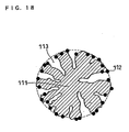
- Fig. 18 shows a schematic sectional view schematically showing catalyst carrying particles, which carry catalyst particles only on the outer surfaces of electroconductive carbon particles.
- an electroconductive carbon particle 111 has fine pores 113, however, catalyst particles 112 are carried only on the outer surface of the electroconductive carbon particle.
- the catalyst carrying particles were heated at 800°C in the air to burn the electroconductive carbon particles, and the weight of the residue was measured, to find that the carried amount of platinum was about 50 wt%.
- the specific surface area of the above-mentioned platinum was measured using an apparatus for adsorbing carbon monoxide (manufactured by Okura Rika K.K.), to find it was 150 m 2 /g per platinum weight.
- a mixture obtained by mixing 2 g of the catalyst carrying particles obtained in the above-mentioned process, 11 g of a solution containing an ion exchange resin dispersed (Flemion manufactured by Asahi Glass Co., Ltd., 9 wt% ethanol solution) and 5 g of water was applied on the surface of a polypropylene sheet by a bar coater and dried, to obtain a catalyst layer.
- the application amount of the catalyst layer was controlled so that the platinum content was 0.2 mg per 1 cm 2 .
- An ion exchange membrane (Gore Select manufactured by Japan Goretex K.K., membrane thickness: 30 ⁇ m) was sandwiched by two of the above-mentioned polypropylene sheet with catalyst layer so that the catalyst layers faced inside, and the obtained laminate was hot-pressed at 130°C for 10 minutes. Then, the polypropylene sheets were removed, and an MEA was obtained by sandwiching with carbon papers (TGP-H-120 manufactured by Toray Industries, Inc., membrane thickness: 360 ⁇ m). The obtained MEA had a structure as shown in Fig. 1.
- a cell for measuring fuel cell property (unit cell P) was manufactured and subjected to tests.
- the structure view of the unit cell is shown in Fig. 2.
- the temperature of the unit cell was set at 75°C, and a hydrogen gas humidified to have a dew point of 80°C was fed at a utilization of 80% to a fuel electrode, and air humidified to have a dew point of 60°C was fed at a utilization of 40% to an air electrode, and a discharge test was conducted.
- Fig. 19 shows a current-voltage (I-V) curve of the unit cell P. In Table 4, current and voltage at 800 mA/cm 2 were shown.
- Ketjen EC was used as the electroconductive carbon particle in the above, when Black-pearls 2000 (manufactured by Cabot, specific surface area: 1500 m 2 /g) was used instead, the specific surface area of platinum became 250 m 2 /g per weight of platinum, obtaining the same result in the current-voltage (I-V) curve.
- the specific surface area of platinum was 50 m 2 /g per weight of platinum, obtaining approximately the same result though a tendency of slight decrease of the current-voltage (I-V) curve was observed.
- electroconductive carbon particles were added 1500 ml of ethanol, 150 ml of water and 60 ml of 25% ammonia water and these were stirred, and 40 ml of 3-aminopropyltriethoxysilane (manufactured by Shin-Etsu Chemical Co., Ltd.) was dropped, and heated while stirring, refluxed and reacted for 2 hours. Then, centrifugal separation and washing with water were repeated, to obtain electroconductive carbon particles of which outer side was more strongly modified.
- 3-aminopropyltriethoxysilane manufactured by Shin-Etsu Chemical Co., Ltd.
- MEA was produced of the same constitution as described above.
- a cell for measuring fuel cell property (unit cell Q) was subjected to a manufacturing test and the same discharge test as described above was conducted.
- Fig. 19 shows a current-voltage curve of the unit cell Q.
- the cell voltage at 800 mA/cm 2 was shown in Table 4.
- the property when methanol was used as a fuel was also evaluated.
- a 2 mol/l aqueous solution of methanol was fed at a temperature of 60°C as a fuel to a fuel electrode, the temperature of the unit cell was set at 75°C, air humidified to have a dew point of 60°C was fed at a utilization of 40% to the air electrode.
- a discharge test was conducted under these conditions.
- a cell voltage of 680 mV was obtained at a current density of 200 mA/cm 2 .
- a cell for measuring fuel cell property (unit cell R) was subjected to a manufacturing test and the same discharge test as described above was conducted.
- Fig. 19 shows a current-voltage curve of the unit cell R.
- the cell voltage at 800 mA/cm 2 was shown in Table 4.
- a cell voltage of 400 mV was obtained at a current density of 200 mA/cm 2 .
- catalyst carrying particles of the present invention can be applied also to other fuel cells such as a direct methanol type fuel cell.
- the relation between a hydrogen ion conductive polymer electrolyte and catalyst particles and carbon particles in a catalyst layer of an electrode of a fuel cell can be clarified, and a fuel cell excellent in power generation property can be provided.
- optimum MEA capable of providing a fuel cell having an excellent power generation ability and a fuel cell power generation system showing excellent system efficiency can be provide.
- the properties of a catalyst layer and a gas diffusion layer constituting MEA, and a water repellent layer capable of being formed between them, can be improved.
- an electrode for fuel cell exhibiting a higher ability by optimizing the water repellency of a carbon fine powder in a catalyst layer and a gas diffusion layer, an electrode for fuel cell exhibiting a higher ability, a polymer electrolyte type fuel cell and liquid fuel cell obtained by using this electrode, can be provided.
Landscapes
- Chemical & Material Sciences (AREA)
- Chemical Kinetics & Catalysis (AREA)
- Electrochemistry (AREA)
- General Chemical & Material Sciences (AREA)
- Engineering & Computer Science (AREA)
- Materials Engineering (AREA)
- Inert Electrodes (AREA)
- Fuel Cell (AREA)
Abstract
To improve the performance of a catalyst layer
for a fuel cell, the weight ratio of a hydrogen ion
conductive polymer electrolyte and electroconductive carbon
particles in a catalyst layer is controlled to satisfy the
formula (1): Y=a · logX-b+c where, log represents natural
logarithm, X represents the specific surface area of the
electroconductive carbon particles (m2/g), Y=(the weight
(g) of the hydrogen ion conductive polymer
electrolyte)/(the weight (g) of the electroconductive
carbon particles), a=0.216, c=±0.300, b=0.421 at an air
electrode and b=0.221 at an fuel electrode.
Description
The present invention relates to a fuel cell.
More particularly, the present invention relates to a
catalyst layer in an electrode which is a constituent
element of a fuel cell.
Fuel cells using polymer electrolytes generate
electric power and heat simultaneously by electrochemically
reacting a fuel gas containing hydrogen with an oxidant gas
containing oxygen such air and the like.
Fig. 1 shows a schematic sectional view of an
electrode membrane assembly (MEA) constituting a polymer
electrolyte type fuel cell. As shown in Fig. 1, a catalyst
layer 12 is formed on both surfaces of a polymer
electrolyte membrane 11 transporting a hydrogen ion
selectively. This catalyst layer 12 is formed of a mixture
obtained by mixing a carbon powder carrying a platinum-type
metal catalyst with a hydrogen ion conductive polymer
electrolyte. Next, on the outside of this catalyst layer
12, a gas diffusion layer 13 having fuel gas permeability
and electron conductivity is formed. As this gas diffusion
layer 13, for example, water-repellent treatment-performed
carbon paper is used. This catalyst layer 12 and the gas
diffusion layer 13 constitute an electrode 14.
For prevention of leakage of a fuel gas and an
oxidant gas out of a fuel cell and prevention of mutual
mixing of these gases, sealing materials are placed such as
gaskets sandwiching a polymer electrolyte membrane, around
the electrode 14. This sealing material is previously
integrated with the electrode 14 and the polymer
electrolyte membrane 11. Thus, the electrode 14 and the
polymer electrolyte membrane 11 constitute MEA 15.
Now, as the polymer electrolyte membrane 11,
perfluorocarbonsulfonic acid having a structure represented
by the formula (2):
 where 5≦x≦13.5, y≒1000, m=1, n=2, is generally used.
Fig. 2 shows a schematic sectional view of a unit
cell using MEA 15 shown in Fig. 1. As shown in Fig. 2, on
the outside of MEA 15, electroconductive separator plates
21 are placed for fixing this mechanically. In parts of
the separator plates 21 in contact with MEA formed are gas
passages 22 for feeding a gas to the electrode 14 and
removing out a produced gas and excess gases. Though the
gas passages 22 can be placed also as separate members on
the separator plate 21, but it is general to form grooves
on the surface of the separator 21, to form gas passages 22.
Thus, by fixing MEA 15 by a pair of separator
plates 21, a unit cell 23 is obtained. An electromotive
force of about 0.8 V can be generated by feeding a fuel gas
to one gas passage 22 and feeding an oxidant gas to another
gas passage 22.
However, when a fuel cell is used as an electric
source, voltages from several volts to several hundreds of
volts are usually necessary. Therefore, actually,
necessary number of unit cells 23 are used connected in
series to be used. In this case, gas passages 22 are formd
on rear and front, both surfaces of the separator plate 21,
and separator plates and MEAs are repeatedly laminated in
the order of separator plate/MEA/separator plate/MEA, and
unit cells 23 are connected in series.
For feeding a gas such as a fuel gas or an
oxidant gas to the gas passage 22, it is necessary that
piping for feeding a gas is branched into the number
corresponding to the number of separator plates 21 to be
used, and ends of the branched piping are allowed to
communicate directly with the gas passages 22 of the
separator plate 21. This jig is called a manifold, and a
manifold communicating gas feeding piping directly with a
separator plate is called an outer manifold. On the other
hand, manifolds include an inner manifold having a simpler
structure. In the case of the inner manifold, a
penetration aperture is provided in a separator plate
having gas passages formed, and the outlet and the inlet of
the gas passage are connected to this aperture, and a gas
is directly fed into this aperture.
Since a fuel cell generates heat in operation, it
is necessary to cool the fuel cell by passing cooling water
and the like, for maintaining the fuel cell at good
temperature condition. Usually, a cooling part through
which cooling water is passed is inserted between separator
plates, every one to three unit cells. The cooling part
may have the same structure as that of the separator plate.
Actually, a passage for cooling water is provided on the
rear surface of the above-mentioned separator plate
(surface not contacting with a gas diffusion layer) to form
a cooling part in many cases.
A plan view schematically showing the structure
of the surface of the above-mentioned separator plate 21 is
shown in Fig. 3, and a plan view schematically showing the
structure of the rear surface of the separator plate is
shown in Fig. 4. As shown in Fig. 3, a passage for a fuel
gas or an oxidant gas is formed on the surface of the
separator plate 21, and as shown in Fig. 4, a passage for
circulating cooling water is formed on the rear surface of
the separator plate 21.
In Fig. 3, a fuel gas is charged from an aperture
31a, and discharged from an aperture 31b. On the other
hand, an oxidant gas is injected from an aperture 32a, and
discharged from an aperture 32b. Cooling water is injected
from an aperture 33a, and cooling water is discharged from
an aperture 33b. A fuel gas injected from an aperture 31a
is introduced to an aperture 31b through a convex part 34
constituting a gas passage, meandering on the way. A
convex part 35 constitutes a gas passage together with the
concave part 34. Then, a fuel gas, oxidant gas and cooling
water are sealed with a sealing material 36.
The separator plate used in such a polymer
electrolyte type fuel cell should have high electric
conductivity and gas tightness against a fuel gas, further,
should have a high corrosion resistance against an
oxidation-reduction reaction between hydrogen and oxygen,
namely, an acid resistance.
Therefore, conventional separators are produced
by forming a gas passage by performing cutting process on
the surface of a plate made of glassy carbon, or filling a
press molding die on which a gas passage has been formed
with a mixture of a binder and an expanded graphite powder,
performing pressing process, then, effecting sintering by
heating, and the like.
Recently, there are trials of using a metal plate
such as a stainless steel plate and the like as the
material of a separator plate, instead of carbon materials
conventionally used. However, a separator plate composed
of a metal plate is exposed to an oxidizing atmosphere at
high temperature, therefore, when used for a long period of
time, this plate is corroded or dissolved. Additionally,
there is a problem that, when a metal plate is corroded,
the electric resistance at the corroded portion increases
and the output of a cell decreases.
Further, when a metal plate is dissolved,
dissolved metal ions diffuse in a polymer electrolyte and
trapped at an ion exchange site in the polymer electrolyte,
leading to decrease in ion conductivity of the polymer
electrolyte itself resultantly. Namely, the polymer
electrolyte itself deteriorates. For avoiding such a
deterioration, it is general to plate the surface of a
metal plate with gold having a certain thickness. Further,
it has also been investigated to produce a separator plate
with a electroconductive resin composition obtained by
mixing an epoxy resin and a metal powder.
MEA, separator plate and cooling part as
described above are laminated alternately to obtain a
laminate composed of 10 to 200 unit cells laminated, and
this laminate is sandwiched with end plates via a
collecting plate and an insulating plate. Then, the end
plates, collecting plates, insulating plates and laminate
are fixed by a fastening volt, to obtain a fuel cell stack.
Fig. 5 is a schematic perspective view of the
fuel cell stack referred to here. In the fuel cell stack
shown in Fig. 5, a necessary number of unit cells 41 are
laminated to constitute a laminate, and the laminate is
sandwiched between two end plates 42 and fastened with a
plurality of fastening volts 43. In Fig. 5, the collecting
plate and the insulating plate are abbreviated. Here, on
the end plate 42, an aperture 44a for charging an oxidant
gas, an aperture 45a for charging a fuel gas and an
aperture 46a for charging cooling water are provided. On
the other hand, an aperture 44b for discharging an oxidant
gas, an aperture 45b for discharging a fuel gas and an
aperture 46b for discharging cooling water are also
provided.
In the electrode of the polymer electrolyte fuel
cell as described above, the size of the area of so-called
three- phase interface formed of a fine pore serving as a
feeding passage for a reaction gas, a hydrogen ion
conductive polymer electrolyte, and a catalyst material
which is an electron conductor affects the discharging
ability of the cell. Conventionally, for increasing the
area of this three-phase interface and decreasing the use
amount of a noble metal which is a catalyst material,
trials have been effected for mixing a hydrogen ion
conductive polymer electrolyte with the catalyst material
and dispersing it. For example, Japanese Patent
Publication Nos. 62-61118 and 62-61119 have suggested a
method in which a mixture of a dispersion or solution of a
polymer electrolyte with a catalyst material is applied on
a polymer electrolyte membrane, this polymer electrolyte
membrane and an electrode material are together hot-pressed
and, then, the catalyst material is reduced.
In Japanese Patent Publication No. 2-48632 has
suggested a method in which a dispersion or solution of an
ion exchange membrane resin is sprayed on a porous
electrode obtained by molding, and this electrode and ion
exchange membrane are hot-pressed. Further, Japanese Laid-Open
Patent Publication No. 3-184266 has suggested a method
in which a powder prepared by coating the surface of a
polymer resin with a polymer electrolyte is mixed in an
electrode, and Japanese Laid-Open Patent Publication No. 3-295172
has suggested a method in which a powder of a
polymer electrolyte is mixed in an electrode.
Japanese Laid-Open Patent Publication No. 5-36418
has suggested a method in which a polymer electrolyte, a
catalyst, a carbon powder and a fluorocarbon resin are
mixed, the obtained mixture is molded in the form of
membrane to obtain an electrode. US Patent No. 5211984 has
suggested a method in which a polymer electrolyte, a
catalyst and a carbon powder are dispersed in the form of
ink into a solvent glycerin or tetrabutylammonium salt, to
prepare a dispersion, a membrane made of the obtained
dispersion is molded on a polytetrafluoroethylene (PTFE)
film, then, the obtained membrane is transferred onto the
surface of a solid polymer electrolyte membrane. Further
reported are a method in which an exchange group of a solid
polymer electrolyte membrane is substituted by Na type, the
above-mentioned dispersion in the form of ink is applied on
the surface of the membrane and heated to dry at a
temperature of 125°C or higher, and the above-mentioned
exchange group is substituted again by H type, and other
methods.
However, if a hydrogen ion conductive polymer
electrolyte is present excessively in a catalyst layer,
electron conductivity in an electrode is remarkably
decreased and simultaneously, a fine pore serving as a
feeding passage for a reaction gas is clogged, decreasing
power generation property. On the other hand, when a
hydrogen ion conductive polymer electrolyte is deficient,
hydrogen ion conductivity lowers, and a power generation
property decreases, problematically. Thus, in a catalyst
layer composed of a hydrogen ion conductive polymer
electrolyte and a carbon powder carrying a catalyst noble
metal, an influence exerted on a power generation property
by the mixing ratio of a catalyst material and a polymer
electrolyte is not apparent yet.
Then, an object of the present invention is to
clarify a relation between a hydrogen ion conductive
polymer electrolyte, catalyst particle and a carbon powder
in a catalyst layer of an electrode of a fuel cell, and to
provide a fuel cell excellent in a power generation
property.
On the other hand, an electrode reaction of a
fuel cell is controlled by diffusion, in a relatively
higher current density region of current density of 0.1
A/cm2 or more. Namely, gas diffusing rate controls the
rate of an electrode reaction. Therefore, for improving
the performance of a cell, it is necessary to improve gas
diffusing efficiency.
For improvement of the gas diffusing efficiency
in a reaction at the air electrode side, oxygen in air,
which is an active substance, cannot efficiently fed to the
electrode unless a product water is not removed efficiently
from the vicinity around the surface of the air electrode.
Therefore, particularly at the air electrode side, an idea
of electrode structure for enhancing diffusing efficiency
was necessary. Usually, therefore, the catalyst layer is
made porous as much as possible by mixing a pore forming
agent in producing a catalyst layer to obtain the layer
through molding and, after the molding, removing the pore
forming agent. Specifically, a porosity of 70% or more is
secured, usually. However, when increase in the porosity
of a catalyst layer and securement of constant catalyst
amount per unit electrode area are intended, the following
problem occurs. For example, for securing a catalyst
amount of about 0.5 mg/cm2, the thickness of a catalyst
layer should be increased relatively. Here, when the
thickness of a catalyst layer is increased, the utilization
efficiency of a catalyst lowers in portions remote far from
a polymer electrolyte membrane in a catalyst layer as
compared with portions adjacent to a polymer electrolyte
membrane. Further, when the thickness of a catalyst layer
becomes larger, the cell performance is improved further,
however, improvement in the cell performance is gradually
saturated. However, sufficient cell performance is not
obtained unless the thickness of a catalyst layer is so
increased.
When MEA for conventional polymer electrolyte
fuel cells is produced, an electrode and a polymer
electrolyte membrane are joined by hot press. Further, for
fastening a stack formed by laminating unit cells, it is
usual to fix this with a fastening pressure of about 10 to
20 kgf/cm2. Anyway, application of high pressure to MEA by
hot press and fastening pressure cannot be avoided,
therefore, particularly when a diffusion layer is
constituted of hard carbon non-woven fabric, a polymer
electrolyte membrane is injured or deformed by the
diffusion layer. Further, there is a risk of formation of
cracking and pinholes and the like on the polymer
electrolyte membrane. When pinholes occur on a polymer
electrolyte membrane, hydrogen as a fuel and air as an
oxidant are cross-leaked and burnt, leading not only to
decrease in the performance of a fuel cell, but also to
increase in the size of pinholes produced on the polymer
electrolyte membrane by burning heat, and in some cases, to
a reverse influence exerted even on a separator plate.
Further, electrical conductivity along the area
direction of the whole electrode is insufficient only by
the electrical conductivity of a catalyst layer and a water
repellent layer, therefore, an electroconductive gas
diffusion layer is generally used also as a gas diffusion
layer. The gas diffusion layer compensates insufficient
electric collection of the catalyst layer and diffuses a
gas, and additionally, exhibits an effect of facilitating
discharge of excess water generated in the catalyst layer
by a cell reaction. Therefore, from the standpoint of gas
diffusing efficiency, a thinner gas diffusion layer is
believed to be more effective. However, from the
standpoint of an effect of discharging excess water, larger
surface area of parts holding water of a gas diffusion
layer is more effective, therefore, when the thickness of a
gas diffusion layer is larger, evaporation of water can be
effectively facilitated. Further, when the thickness of a
gas diffusion layer is decreased, pressure loss of a
feeding gas increases, and when an efficiency of the whole
fuel cell power generation system is taken into
consideration, auxiliary mobility increases and the system
efficiency decreases, problematically.
Then, another object of the present invention is
to provide optimum MEA capable of producing a fuel cell
having an excellent power generation performance and a fuel
cell power generation system having an excellent system
efficiency. In this point, the present invention relates
to a catalyst layer and a gas diffusion layer particularly
constituting MEA, and a water repellent layer which can be
formed between them.
Next, the gas diffusion layer and catalyst layer
constituting an electrode of a fuel cell as described above
will be explained particularly in detail below. The gas
diffusion layer has mainly the following three functions.
The first function is a function of diffusing a reaction
gas such as a fuel gas or oxidant gas so as to uniformly
feed the reaction gas from a gas passage formed on a
further outer surface of the gas diffusion layer to the
catalyst in the catalyst layer. The second function is a
function of quickly discharging water produced by a
reaction in a catalyst layer, into a gas passage. The
third function is a function of conducting electrons
necessary for a reaction or generated electrons. Namely,
the gas diffusion layer is required to have high reaction
gas permeability, water vapor permeability and electron
conductivity.
As a conventional general technology, the gas
diffusion layer having a porous structure is obtained by
using a carbon fine powder having a developed structure, a
pore forming agent, and an electroconductive porous
substrate such as carbon paper or carbon cloth, for
imparting gas permeability to the gas diffusion layer. For
imparting water vapor permeability to the gas diffusion
layer, water repellent polymers typified by fluorocarbon
resins and the like are diffused in the gas diffusion layer.
Further, for imparting electron conductivity, the gas
diffusion layer is constituted of an electron conductive
material such as carbon fiber, metal fiber and carbon fine
fiber.
The catalyst layer has mainly the following four
functions. The first function is a function of feeding a
reaction gas such as a fuel gas or oxidant gas fed from the
gas diffusion layer to a reaction site of the catalyst
layer. The second function is a function of quickly
transferring hydrogen ions necessary for a reaction on the
catalyst or produced hydrogen ions, to an electrolyte
membrane. Further, the third function is a function of
transferring electrons necessary for a reaction or
generated electrons. The fourth function is a high
catalyst ability for quick reaction and the wide reaction
area thereof. Namely, the catalyst layer is required to
have high reaction gas permeability, hydrogen ion
permeability, electron conductivity and catalyst ability.
As a conventional general technology, the
catalyst layer having a porous structure is obtained by
using a carbon fine powder having a developed structure and
a pore forming agent, for imparting gas permeability to the
catalyst layer. Further, for imparting hydrogen ion
permeability to the catalyst layer, a polymer electrolyte
is dispersed in portions around a catalyst in the catalyst
layer, and a hydrogen ion network is formed. For impacting
electron conductivity to the catalyst layer, an electron
conductive material such as a carbon fine powder or a
carbon fiber is used as a catalyst carrier. Further, for
improving a catalyst ability, a metal catalyst having high
reaction activity typified by platinum is prepared to have
a particle size of several nm, this very fine particle is
carried on a carbon fine powder, and the obtained catalyst
carrying particles are dispersed in the catalyst layer.
Here, the electroconductive carbon particle
(carbon fine particle) used in the gas diffusion layer and
the catalyst layer of the above-mentioned MEA is explained.
The carbon fine powder is a black powder of amorphous
carbon having a diameter of 3 to 500 nm, not easily wetted
with water, and has a specific gravity of 1.8 to 1.9 and an
apparent specific gravity of 0.35 to 0.4 in terms of
particle and 0.04 to 0.08 in terms of powder. Though the
carbon fine powder can be produced by thermally decomposing
hydrocarbons, extremely various products are obtained
depending on differences in production methods, production
conditions and the like. In any method, a raw material
hydrocarbon is carbonized at a high temperature of 800°C or
higher for a short period of time such as several milliseconds.
In a crystal structure as a base of a carbon fine
powder, crystallites having a disorderly layered structure,
which comprises a several layers of aromatic plane
molecules having an average size of 10 to 30Å, aggregate
complicatedly to constitute spherical particles. These
spherical particles further bond to constitute an aggregate
(structure) in the form of chain. The microscopic
condition of the surface of this carbon fine powder differs
from the condition of a simple fine particle of carbon, and
an acidic functional group and other functional group are
present on the surface of the particle, therefore, it has
special industrial applications such as a rubber
reinforcing agent.
The hydrocarbons used for a raw material include
natural gas, coal gas, acetylene gas, petroleum-based heavy
oil, petroleum, creosote oil, naphthalene, anthracene and
the like, and classified into gas black, oil black,
acethylene black and the like depending on the raw material.
90% or more of the carbon fine powder are used as
various rubber reinforcing agents (about 80% of them are
for tires), and widely used for plastic reinforcing fillers,
printing inks, paints, electric wires, electric columns and
dry batteries, as well as carbon paper, Japanese ink,
pigments, pencils, crayons, catalyst carriers, fireworks
and thawing agents and the like.
The main method of producing the carbon fine
powder is as described below. The currently dominant
furnace method was developed in U.S. during The World War
II, and gases were used as a raw material at first, however,
recently oils are used, and those of high quality are
obtained at high yield. A raw material and air are blown
into a furnace (burning furnace), the raw material is
incompletely burnt continuously under turbulent diffusion,
a burnt gas passed through a cooler is collected in a bag
filter in the form of bag and is granulated. For example,
the furnace temperature is about 1600°C, the burnt products
are hydrogen, carbon monoxide, carbon dioxide, water vapor
and carbon black (furnace black). Cooling is conducted by
spraying water, and first, the primary cooling temperature
is controlled at 900°C and the second cooling temperature
is controlled at 400°C.
In the thermal method, natural gas as a raw
material is fed to a sufficiently heated checker structure
(obtained by combining fireproof red bricks with clearance)
to cause thermal decomposition, and a cycle mode operation
is conducted without using oxygen.
However, since the wetting property of the carbon
fine powder used in such a catalyst layer and gas diffusion
layer increases with the lapse of time, it is a problem
that fine pores serving as a reaction gas feeding passage
are clogged in the catalyst layer and the gas diffusion
layer, by the produced water and water contained in a
reaction gas for moistening. Consequently, a reaction gas
is not fed sufficiently, causing decrease in the cell
performance.
A reason for increase in wetting property of such
a carbon fine powder is believed in that since a
conventionally used carbon fine powder is insufficiently
graphitized, various functional groups are present on the
surface, surface energy for water is high, and contact
angle is small and, consequently, moisture absorption
proceeds gradually.
Then, still another object of the present
invention is to solve the above-mentioned conventional
problems, and to provide an electrode for fuel cell
exhibiting higher performance by optimizing the water
repellency of a carbon fine particle in a catalyst layer
and a gas diffusion layer, and a polymer electrolyte type
fuel cell and a liquid fuel cell using this electrode.
The present invention relates to a fuel cell
comprising a hydrogen ion conductive polymer electrolyte
membrane, a pair of electrodes disposed sandwiching the
hydrogen ion conductive polymer electrolyte membrane, and a
pair of separator plates having gas passages feeding a fuel
gas to and discharging a fuel gas from one of the
electrodes and feeding an oxidant gas to and discharging an
oxidant gas from another electrode, wherein
the electrode has a gas diffusion layer and a catalyst layer in contact with the hydrogen ion conductive polymer electrolyte membrane,
the catalyst layer comprises a hydrogen ion conductive polymer electrolyte and electroconductive carbon particles carrying catalyst particles, and
the hydrogen ion conductive polymer electrolyte and the electroconductive carbon particles in the catalyst layer satisfy the formula (1):Y=a · logX-b+c
where, log represents natural logarithm, X represents the
specific surface area of the electroconductive carbon
particles (m2/g), Y=(the weight (g) of the hydrogen ion
conductive polymer electrolyte)/(the weight (g) of the
electroconductive carbon particles), a=0.216, c=±0.300,
b=0.421 at an air electrode and b=0.221 at an fuel
electrode.).
the electrode has a gas diffusion layer and a catalyst layer in contact with the hydrogen ion conductive polymer electrolyte membrane,
the catalyst layer comprises a hydrogen ion conductive polymer electrolyte and electroconductive carbon particles carrying catalyst particles, and
the hydrogen ion conductive polymer electrolyte and the electroconductive carbon particles in the catalyst layer satisfy the formula (1):
It is effective that the catalyst layer contains
electroconductive carbon particles having a particle size
of the primary particle of 10 nm or more and 150 nm or less,
a hydrogen ion conductive polymer electrolyte and platinum,
and has a thickness of 3 µm or more and 10 µm or less.
It is effective that the electrode has a water
repellent layer between the catalyst layer and the gas
diffusion layer, the water repellent layer contains
electroconductive carbon particles having a particle size
of the primary particle of 10 nm or more and 150 nm or less
and a water repellent agent, portions of the water
repellent layer not intruding into the gas diffusion layer
have an average thickness of 5 µm or more and 50 µm or
less.
It is effective that the average thickness of the
gas diffusion layer is 250 µm or more and 400 µm or less.
It is effective that the catalyst layer has a
porosity of 30% or more and 70% or less, and the water
repellent layer has a porosity of 30% or more and 60% or
less.
It is effective that the fuel cell has a sealing
material on the peripheral parts of the electrode, and the
distance between the electrode and the above-mentioned
sealing material is 10 µm or more and 1 mm or less.
It is effective that the hydrogen ion conductive
polymer electrolyte has a main chain skeleton comprised of
fluorocarbon and a side chain having an end group comprised
of sulfonic acid or alkylsulfonic acid, and has an
equivalent weight of 80 g/Eq or more and 110 g/Eq or less.
It is effective that the electroconductive carbon
particles have a specific surface area of 50 m2/g or more
and 1500 m2/g or less.
It is effective that the electroconductive carbon
particles contain a graphitized carbon powder in an amount
of 33% by weight or more.
It is effective that the lattice plane spacing
d002 of the (002) plane in the crystal structure of the
above-mentioned graphitized carbon powder is 3.35Å or more
and 3.44Å or less.
It is effective that the graphitized carbon
powder is one obtained by thermally treating a carbon
powder at 2000°C or more.
It is effective that the electroconductive carbon
particles have a specific surface area of 58 m2/g or more
and 1500 m2/g or less, and the catalyst particles are
carried only on the outside of the electroconductive carbon
particles.
It is effective that an end cation part composed
of a polar functional group present on the outer surface of
the electroconductive carbon particle is substituted by a
catalyst cation.
It is effective that the catalyst particles have
a specific surface area of 50 m2/g or more and 250 m2/g or
less.
As described above, the present invention is
characterized in that, in an electrode having a gas
diffusion layer and a catalyst layer in a fuel cell, the
catalyst layer is formed of a hydrogen ion conductive
polymer electrolyte and electroconductive carbon particles
carrying catalyst particles, and the weight of the hydrogen
ion conductive polymer electrolyte and the weight of the
electroconductive carbon particles in the catalyst layer
are controlled to satisfy the formula (1):
Y=a · logX-b+c
where, log represents natural logarithm, X represents the
specific surface area of the electroconductive carbon
particles (m2/g), Y=(the weight (g) of the hydrogen ion
conductive polymer electrolyte)/(the weight (g) of the
electroconductive carbon particles), a=0.216, c=±0.300,
b=0.421 at an air electrode and b=0.221 at an fuel
electrode.
It is effective that the catalyst layer contains
electroconductive carbon particles having a particle size
of the primary particle of 10 nm or more and 150 nm or less,
a hydrogen ion conductive polymer electrolyte and platinum,
and has a thickness of 3 µm or more and 10 µm or less.
It is effective that the electrode has a water
repellent layer between the catalyst layer and the gas
diffusion layer, the water repellent layer contains
electroconductive carbon particles having a particle size
of the primary particle of 10 nm or more and 150 nm or less
and a water repellent agent, portions of the water
repellent layer not intruding into the gas diffusion layer
have an average thickness of 5 µm or more and 50 µm or
less.
It is effective that the average thickness of the
gas diffusion layer is 250 µm or more and 400 µm or less.
It is effective that the catalyst layer has a
porosity of 30% or more and 70% or less, and the water
repellent layer has a porosity of 30% or more and 60% or
less.
It is effective that the fuel cell has a sealing
material on the peripheral parts of the electrode, and the
distance between the electrode and the sealing material is
10 µm or more and 1 mm or less.
It is effective that the hydrogen ion conductive
polymer electrolyte has a main chain skeleton comprised of
fluorocarbon and a side chain having an end group comprised
of sulfonic acid or alkylsulfonic acid, and has an
equivalent weight of 80 g/Eq or more and 1100 g/Eq or less.
The "equivalent weight" means the weight of the whole
electrolyte giving 1 mol of sulfone group.
It is effective that the electroconductive carbon
particles have a specific surface area of 50 m2/g or more
and 1500 m2/g or less.
It is effective that the electroconductive carbon
particles contain a graphitized carbon powder in an amount
of 33% by weight or more.
It is effective that the lattice plane spacing
d002 of the (002) plane in the crystal structure of the
graphitized carbon powder is 3.35Å or more and 3.44Å or
less.
It is effective that the graphitized carbon
powder is obtained by thermally treating a carbon powder at
2000°C or more.
It is effective that the electroconductive carbon
particles have a specific surface area of 58 m2/g or more
and 1500 m2/g or less, and the catalyst particles are
carried only on the outside of the electroconductive carbon
particles.
It is effective that an end cation part composed
of a polar functional group present on the outer surface of
the above-mentioned electroconductive carbon particle is
substituted by a catalyst cation.
It is effective that the catalyst particles have
a specific surface area of 50 m2/g or more and 250 m2/g or
less.
First, MEA was produced according to the
following method. A dispersion of polytetrafluoroethylene
(Lubron LDW-40 manufactured by Daikin Industries, Ltd.) was
mixed in an amount of 30% by weight by dry weight with an
electroconductive carbon particle powder (Denka Black
manufactured by Denki Kagaku Kogyo K.K.), to produce a
water repellent layer ink. Next, the water repellent layer
ink was applied on the surface of carbon paper
(manufactured by Toray Industries, Inc.: TGPH060H), and
heated at 350°C by a hot air dryer, to form a gas diffusion
layer.
Then, platinum particles having an average
particle size of about 30Å were carried on
electroconductive carbon particles having a specific
surface area of 70 m2/g (Denka Black manufactured by Denki
Kagaku Kogyo K.K.), to obtain catalyst carrying particles.
25% by weight of the catalyst carrying particles were
platinum particles. The catalyst carrying particles and a
dispersion or solution of a hydrogen ion conductive polymer
electrolyte were mixed to obtain a catalyst paste. In this
procedure, the catalyst carrying particles and the hydrogen
ion conductive polymer electrolyte were mixed so that the
weight ratio represented by polymer
electrolyte/electroconductive carbon particles was 0.2 to
2.0. As the hydrogen ion conductive polymer electrolyte, a
perfluorocarbonsulfonic acid having an equivalent weight of
1000 to 1100 g/Eq was used.
Next, on one surface of the gas diffusion layer
and on both surfaces of a hydrogen ion conductive polymer
electrolyte membrane (Nafion 112 manufactured by E. I. Du
Pont de Nemours and Company, U.S.), the catalyst paste was
printed. The gas diffusion layer on the fuel electrode
side and the gas diffusion layer on the air electrode side
were laminated so that the catalyst paste surfaces faced
while mutually sandwiching the hydrogen ion conductive
polymer electrolyte membrane at the center, and these were
connected by a hot press method. By this, a membrane
electrode assembly (MEA) was obtained. A gasket plate made
of butyl rubber was connected to the outer peripheral parts
of the polymer electrolyte membrane of the MEA, and
manifold apertures for passing cooling water, fuel gas and
oxidant gas were formed on the gasket plate.
Next, separator plates constituted of a resin
impregnated graphite plate with a dimension of
20cm×32cm×1.3mm and having gas passages and cooling water
passages of a depth of 0.5 mm were prepared. On one
surface of MEA, a separator plate having oxidant gas
passages formed was laminated, and on another surface of
MEA, a separator plate containing fuel gas passages formed
was laminated, to obtain a unit cell. Two of this unit
cell were laminated, then, this two cell-laminated cell was
sandwiched by the separator plates having cooling passages
formed. A plurality of this two unit cell laminate were
laminated, to produce a cell stack containing 100 unit
cells. Then, at both ends of the cell stack, a collecting
plate made of stainless steel, an insulating plate made of
an electrically insulating material and an end plate were
fixed by a fastening rod. The fastening pressure under
this condition was 10 kgf/cm2 per area of the separator
plate.
A pure hydrogen gas was fed to the fuel electrode
and air was fed to the air electrode, of thus produced
polymer electrolyte fuel cell in this example. Under
conditions of a cell temperature of 75°C, a fuel gas
utilization (Uf) of 70% and an air utilization (Uo) of 40%,
the cell property of the above-mentioned cell stack was
evaluated. The fuel gas was passed through hot water of
75°C for humidification, and air was passed through hot
water of 50°C for humidification. Fig. 6 shows the output
voltage when the current density was 700 mA/cm2. Fig. 6 is
a graph showing the relation between the ratio of polymer
electrolyte/electroconductive carbon particles and the
output voltage per unit cell.
From Fig. 6, it was found that when the specific
surface are of electroconductive carbon particles is 70
m2/g and catalyst carrying particles carry 25 wt% of
platinum particles, the weight ratio of polymer
electrolyte/electroconductive carbon particles at which the
output voltage is most excellent is 0.5 (Example 1).
In Example 1, platinum was carried on
electroconductive carbon particles having a specific
surface of 70 m2/g, next, electroconductive carbon
particles having a specific surface of 250 m2/g (Vulcan XC
manufactured by Cabot) were used. A cell was produced in
the same constitution as in Example 1 excepting the above-mentioned
electroconductive carbon particle, and tested in
the same conditions as in Example 1. The results are shown
in Fig. 7.
From Fig. 7, it was found that when the specific
surface of electroconductive carbon particles is 250 m2/g
and catalyst carrying particles carry 25 wt% of platinum
particles, the weight ratio of polymer
electrolyte/electroconductive carbon particles at which the
output voltage is most excellent is 0.8 (Example 2).
Next, platinum was carried on electroconductive
carbon particle having a specific surface area of 800 m2/g
(Ketjen Black EC manufactured by Lion Corp.). A cell was
produced in the same constitution as in Example 1 excepting
the above-mentioned electroconductive carbon particle, and
tested in the same conditions as in Example 1. The results
are shown in Fig. 8.
From Fig. 8, it was found that when the specific
surface of electroconductive carbon particles is 800 m2/g
and catalyst carrying particles carry 25 wt% of platinum
particles, the weight ratio of polymer
electrolyte/electroconductive carbon particles at which the
output voltage is most excellent is 0.9 (Example 3).
Next, the above-mentioned platinum particles were
carried on electroconductive carbon particle having a
specific surface area of 1270 m2/g (Ketjen Black 600 JD
manufactured by Lion Corp.). A cell was produced in the
same constitution as in Example 1 excepting the above-mentioned
electroconductive carbon particle, and tested in
the same conditions as in Example 1. The results are shown
in Fig. 9.
From Fig. 9, it was found that when the specific
surface of electroconductive carbon particles is 1270 m2/g
and catalyst carrying particles carry 25 wt% of platinum
particles, the weight ratio of polymer
electrolyte/electroconductive carbon particles at which the
output voltage is most excellent is 1.2 (Example 4).
Though 25 wt% of platinum was carried on
electroconductive carbon particles having a specific
surface area of 800 m2/g in Example 1, 50 wt% of platinum
was carried in this example. Namely, 50 wt% of catalyst
carrying particles were platinum particles. A cell was
produced in the same constitution as in Example 1 excepting
the above-mentioned electroconductive carbon particle, and
tested in the same conditions as in Example 1. The results
are shown in Fig. 10.
From Fig. 10, it was found that when the specific
surface of electroconductive carbon particles is 800 m2/g
and catalyst carrying particles carry 25 wt% of platinum
particles, the weight ratio of polymer
electrolyte/electroconductive carbon particles at which the
output voltage is most excellent is 1.0 (Example 5).
Though a perfluorocarbonsulfonic acid having an
equivalent weight of 1000 to 1100 g/Eq was used in
preparing the catalyst paste in Example 1, a
perfluorocarbonsulfonic acid having an equivalent weight of
900 g/Eq was used in this example. A catalyst past was
prepared with this perfluorocarbonsulfonic acid and
catalyst carrying particles (containing 50 wt% of platinum
particles) obtained by carrying platinum particles on
electroconductive carbon particles having a specific
surface area of 800 m2/g (Ketjen Black EC manufactured by
Lion Corp.). A cell was produced in the same constitution
as in Example 1 excepting the above-mentioned conditions,
and tested in the same conditions as in Example 1. The
results are shown in Fig. 11.
From Fig. 11, it was found that when the specific
surface of electroconductive carbon particles is 800 m2/g
and a hydrogen ion conductive polymer has an equivalent
weight of 900 g/Eq, the weight ratio of polymer
electrolyte/electroconductive carbon particles at which the
output voltage is most excellent is 1.1 (Example 6).
Next, a catalyst paste was prepared using a
perfluorocarbonsulfonic acid having an equivalent weight of
800 to 850 g/Eq. A cell was produced in the same
constitution as in Example 6 excepting the above-mentioned
condition, and tested in the same conditions as in Example
1. The results are shown in Fig. 12.
From Fig. 12, it was found that when the specific
surface of electroconductive carbon particles is 800 m2/g
and a polymer has an equivalent weight of 800 to 850 g/Eq,
the weight ratio of polymer electrolyte/electroconductive
carbon particles at which the output voltage is most
excellent is 1.0 (Example 7).
Based on the above-mentioned results, Fig. 13
shows the relation between the weight ratio of polymer
electrolyte/electroconductive carbon particles and the
specific surface area of electroconductive carbon particles,
at which the output voltage is most excellent, in Figs. 6
to 12. A straight line was drawn in Fig. 13 and this line
was analyzed, to obtain a formula: y=0.2164 · logX-0.421.
When the inclination of the above-mentioned straight line
was changed in the permissible range in Fig. 8, a formula
(1): Y=a · logX-b+c where, log represents natural logarithm,
X represents the specific surface area of the
electroconductive carbon particles, Y=(the weight (g) of
the hydrogen ion conductive polymer electrolyte)/(the
weight (g) of the electroconductive carbon particles),
a=0.216, c=±0.300, b=0.421 at an air electrode and b=0.221
at an fuel electrode, was obtained. Namely, it was found
preferable that the hydrogen ion conductive polymer
electrolyte, catalyst particles and electroconductive
carbon particles in the above-mentioned catalyst layer
satisfy the formula (1). Particularly, it was found
preferable that b=0.421 at an air electrode and b=0.221 at
an fuel electrode.
From Fig. 13, it was found that polymer
electrolyte/electroconductive carbon particles at which the
output voltage is most excellent is scarcely dependent on
the Pt carrying ratio and the equivalent weight of a
hydrogen ion conductive polymer electrolyte dispersed in
the catalyst. Namely, it was found that the output voltage
of a fuel cell can be enhanced by controlling the amount of
a hydrogen ion conductive polymer electrolyte introduced in
the catalyst layer according to the formula (1) from the
specific surface area of electroconductive carbon particles
used as a catalyst material. As described above, the
output performance of a fuel cell can be enhanced according
to the present invention.
Next, the following examples were conducted to
find suitable constitutions of a catalyst layer, water
repellent layer, gas diffusion layer and the like.
Electroconductive carbon particles having a
particle size of the primary particle of 10 nm or more and
150 nm or less (Vulcan XC manufactured by Cabot) were
allowed to carry platinum particles having an average
particle size of 30Å to obtain catalyst carrying particles
for an air electrode (containing 50 wt% of platinum
particles). Further, the carbon black was allowed to carry
platinum-ruthenium alloy particles having an average
particle size of 30Å to obtain catalyst carrying particles
for a fuel electrode (containing 50 wt% of platinum-ruthenium
alloy particles). As the hydrogen ion conductive
polymer electrolyte, a perfluorosulfonic acid of a chemical
formula shown in the formula (2) was used.
20 parts by weight of the catalyst carrying
particles and 80 parts by weight of an ethanol dispersion
or solution containing 9 wt% of hydrogen ion conductive
polymer electrolyte were mixed by ball mill to prepare an
electrode ink. In this case, for producing a catalyst
layer having a thickness of over 10 µm and having large
porosity for comparison, 20 wt% of a pore forming agents
was added to the electrode ink to prepare an electrode ink.
After production of a catalyst layer containing the pore
forming agent, the pore forming agent was removed by
thermal treatment.
Then, an ethanol dispersion or solution
containing 9 wt% of a hydrogen ion conductive polymer
electrolyte was cast on a smooth glass substrate, and dried
to obtain a hydrogen ion conductive polymer electrolyte
membrane having an average membrane thickness of 30 µm.
Then, on both surfaces of this hydrogen ion conductive
polymer electrolyte membrane, the electrode ink and the
pore forming agent-containing electrode ink were printed by
a screen printing method, to obtain a polymer electrolyte
membrane with catalyst layer.
Carbon paper was used as the gas diffusion layer,
and water repellent treatment was performed on this.
Carbon non-woven fabric (TGP-H-120 manufactured by Toray
Industries, Inc.) of 16cm×20cm×360µm was immersed in an
aqueous dispersion containing a fluorocarbon resin (Neofron
ND1 manufactured by Daikin Industries, Ltd.), then, this
was dried, and heated at 400°C for 30 minutes, to give
water repellency.
Next, electroconductive carbon particles (carbon
black) having a particle size of the primary particle of 10
nm or more and 150 nm or less and an aqueous dispersion of
a PTFE powder were mixed, to prepare a water repellent
layer ink.
Further, the water repellent layer ink was
applied by a screen printing method to form a water
repellent layer on one surface of the carbon non-woven
fabric which was a gas diffusion layer. In this condition,
a part of the water repellent layer was intruded into,
namely, buried into the carbon non-woven fabric, and by
controlling the viscosity of the water repellent layer ink,
the thickness of parts of the water repellent layer not
intruded into the diffusion layer was controlled.
Then, on both surfaces of the polymer electrolyte
membrane with catalyst layer, a pair of diffusion layers
with water repellent layer were bonded by a hot press so
that the water repellent layer was in contact with the
catalyst layer on the polymer electrolyte membrane,
obtaining a membrane/electrode assembly (MEA).
This MEA was thermally treated for 1 hour in a
saturated water vapor atmosphere of 120°C, to allow
conducting passages to develop sufficiently. Here, it was
found that when a hydrogen ion conductive polymer
electrolyte of the formula (2) is thermally treated under a
wet atmosphere of a relatively high temperature of about
100°C of more, a hydrophilic channel as a hydrogen ion
conductive passage is developed, to form a reverse micelle
structure.
Thus, an electrode of 16cm×20cm was connected on
both surfaces of a hydrogen ion conductive polymer
electrolyte membrane of 20 cm×32 cm, to obtain MEA
containing electroconductive carbon particles carrying a
catalyst for electrode reaction.
Next, a gasket plate made of rubber was connected
to the outer peripheral parts of the polymer electrolyte
membrane of MEA, and manifold apertures for passing cooling
water, fuel gas and oxidant gas were formed.
Then, separator plates constituted of a resin-impregnated
graphite plate with a dimension of
20cm×32cm×1.3mm and having gas passages and cooling water
passages of a depth of 0.5 mm were prepared. On one
surface of MEA, a separator plate having oxidant gas
passages formed was laminated, and on another surface of
MEA, a separator plate having fuel gas passages formed was
laminated, to obtain a unit cell. Two of this unit cell
were laminated, then, sandwiched by the separator plates
having cooling passages formed, to obtain a laminate
composed of two unit cells. A plurality of this laminate
were laminated, to produce a cell stack containing 100 unit
cells. Then, at both ends of the cell stack, a collecting
plate made of stainless steel, an insulating plate made of
an electrically insulating material and an end plate were
fixed by fastening rods. The fastening pressure under this
condition was 10 kgf/cm2 per area of the separator plate.
Thus produced polymer electrolyte fuel cell of
this example thus produced was maintained at 80°C, and a
hydrogen gas humidified and heated so as to have a due
point of 75°C, and having a lowered carbon monoxide
concentration of 50 ppm or less by modifying methane with
water vapor was fed to one electrode, and air humidified
and heated so as to have a due point of 50°C was fed to
another electrode.
This cell stack was subjected to a continuous
power generation test under conditions of a fuel
utilization of 85%, an oxygen utilization of 60% and a
current density of 0.7 A/cm2, and change by time of the
output property was measured.
Tables 1 and 2 show combinations of the catalyst
layer, water repellent layer and diffusion layer and the
results of the power generation test.
| Catalyst layer | Water repellent layer | Diffusion layer | Initial properties | Properties after 5000 hours | |||
| Thickness (µm) | Catalyst layer mg/cm2 | Thickness (µm) | Thickness (µm) | Open voltage (V) | Voltage in power generation at 0.7 A/cm2 | Open voltage (V) | Voltage in power generati on at 0.7 A/cm2 |
| 10 | 0.5 | 20 | 350 | 99.5 | 66.5 | 99.0 | 65.0 |
| 10 | 0.2 | 20 | 350 | 98.5 | 65.5 | 98.0 | 64.0 |
| 10 | 0.1 | 20 | 350 | 98.0 | 64.0 | 97.0 | 62.0 |
| 10 | 0.05 | 20 | 350 | 97.0 | 62.0 | 96.0 | 60.0 |
| 7 | 0.5 | 20 | 350 | 100.0 | 67.0 | 99.5 | 66.0 |
| 7 | 0.2 | 20 | 350 | 99.0 | 66.0 | 97.5 | 64.5 |
| 7 | 0.1 | 20 | 350 | 97.5 | 63.0 | 96.0 | 61.5 |
| 7 | 0.05 | 20 | 350 | 96.0 | 62.5 | 95.0 | 60.0 |
| 3 | 0.5 | 20 | 350 | 99.0 | 66.5 | 98.5 | 65.0 |
| 3 | 0.2 | 20 | 350 | 98.0 | 65.0 | 96.5 | 63.0 |
| 3 | 0.1 | 20 | 350 | 97.0 | 62.0 | 96.5 | 60.5 |
| 3 | 0.05 | 20 | 350 | 95.5 | 61.5 | 94.0 | 60.0 |
| 7 | 0.2 | 5 | 350 | 99.5 | 66.5 | 92.5 | 60.5 |
| 7 | 0.2 | 10 | 350 | 99.5 | 66.0 | 94.0 | 61.5 |
| 7 | 0.2 | 30 | 350 | 99.0 | 66.0 | 98.0 | 65.0 |
| 7 | 0.2 | 50 | 350 | 97.5 | 65.5 | 97.0 | 64.4 |
| 7 | 0.2 | 20 | 250 | 99.5 | 65.5 | 99.0 | 65.0 |
| 7 | 0.2 | 20 | 400 | 99.0 | 66.0 | 98.0 | 64.5 |
| Catalyst layer | Water repellent layer | Diffusion layer | Initial properties | Properties after 5000 hours | |||
| Thickness (µm) | Catalyst layer mg/cm2 | Thickness (µm) | Thickness (µm) | Open voltage (V) | Voltage in power generation at 0.7 A/cm2 | Open voltage (V) | Voltage in power generati on at 0.7 A/cm2 |
| 50 | 1.0 | 20 | 350 | 97.0 | 58.0 | 92.5 | 50.5 |
| 50 | 0.5 | 20 | 350 | 96.0 | 55.0 | 94.0 | 43.0 |
| 20 | 1.0 | 20 | 350 | 98.0 | 60.5 | 97.0 | 53.5 |
| 20 | 0.5 | 20 | 350 | 97.0 | 56.5 | 95.0 | 45.0 |
| 15 | 1.0 | 20 | 350 | 97.5 | 62.0 | 95.0 | 56.0 |
| 15 | 0.5 | 20 | 350 | 96.0 | 60.5 | 93.5 | 57.0 |
| 15 | 0.2 | 20 | 350 | 93.5 | 55.5 | 88.5 | 48.0 |
| 2 | 0.5 | 20 | 350 | 92.0 | 60.5 | 88.0 | 52.5 |
| 2 | 0.2 | 20 | 350 | 90.0 | 56.5 | 86.5 | 50.0 |
| 2 | 0.1 | 20 | 350 | 88.5 | 51.5 | 86.0 | 40.5 |
| 7 | 0.2 | 3 | 350 | 97.5 | 60.5 | 82.5 | 20.5 |
| 7 | 0.2 | 60 | 350 | 92.0 | 55.5 | 90.0 | 47.5 |
| 7 | 0.2 | 20 | 150 | 98.5 | 55.5 | 90.5 | 50.5 |
| 7 | 0.2 | 20 | 200 | 97.5 | 58.0 | 95.5 | 50.5 |
| 7 | 0.2 | 20 | 450 | 99.5 | 47.5 | 99.0 | 40.5 |
| 7 | 0.2 | 20 | 500 | 100.0 | 40.5 | 99.0 | 22.5 |
As apparent from the descriptions of the above-mentioned
examples, when an electrode using a catalyst
layer, water repellent layer and diffusion layer having a
specific constitution is used, a polymer electrolyte fuel
cell having higher initial properties and life property can
be obtained. Since a catalyst layer can be produced
without adding a pore forming material in producing a
catalyst layer, cost reduction and abbreviation of
processes are possible. Further, by maintaining the
porosity of the catalyst layer lower and decreasing the
thickness of a catalyst layer, a cell of high performance
can be obtained even at a lower humidification temperature.
Namely, it is effective that the thickness of the
catalyst layer is 3 µm or more and 10 µm or less, the
average thickness of parts of the water repellent layer not
intruding into the gas diffusion layer is 5 µm or more and
50 µm or less, and the average thickness of the above-mentioned
gas diffusion layer is 250 µm or more and 400 µm
or less.
Next, the electroconductive carbon particle was
investigated.
The graphitized carbon fine powder
(electroconductive carbon particle) has lower surface
energy as compared with water since its surface has a
graphite structure, and does not easily absorb moisture
since contact angle for water is large. Further, since the
number of functional groups on the surface such as -CO,
-COOH, -CHO and -OH decreases by thermal treatment at 2000°C
or more in the graphitization process, bonding force with
water is further suppressed. Therefore, the water
repellency of a carbon powder is improved, leading to lower
tendency of wetting.
According to such a theory, a phenomenon, in
which a carbon fine powder is gradually moistened by water
vapor added to a reaction gas for allowing a polymer
electrolyte to contain water and by produced water, and dew
is generated in fine pores of the catalyst layer and the
gas diffusion layer to clog gas passages to lower a gas
feeding ability and a produced water discharging ability,
is suppressed and high gas permeability and produced water
discharging ability can be obtained. As a result, there is
obtained an effect that a higher cell performance is
manifested for a long period of time and the life property
of a fuel cell is improved.
The graphitized carbon powder in the present
invention is obtained by graphitizing a carbon powder. As
the carbon powder, conventionally known carbon black can be
used such as acethylene black, oil furnace black, channel
black and thermal black, and powders of various classes can
be used. As the commercially available powders, for
example, Vulcan XC-72 manufactured by Cabot K.K., Ketjen
Black manufactured by Ketjen Black International K.K., N330
manufactured by Showa Denko K.K. and the like are listed.
The particle size of the carbon powder may be 10
to 70 nm, further, preferably from 10 to 40 nm, for
increase of the specific surface area carrying a catalyst
metal. Therefore, N330, N339, N326, N347, N351, N219, N220,
N242, N285, N110, S301, S200 and the like can be used.
Here, Fig. 14 shows a schematic sectional view
schematically showing the structures of the primary
particles of a graphitized carbon powder (a) and a usual
carbon powder (b). Fig. 15 shows a concept view of the
crystal structure of natural graphite. Carbon Material
Institute magazine, Carbon Material Introduction (tanso
zairyo nyumon) p.180, and Jean-Baptiste Donnet, Andries
Voer, "Carbon Black" (supervised and translated by
Takahashi, Yamashita, Tsutsumi, Kodansha Scientific) pp.78
to 99 describe that the fine crystal structure of carbon
black, which is a carbon powder conventionally used in
general, is a structure as shown in Fig. 15 according to X-ray
diffraction. Namely, it is described that layers
connecting hexa-carbon rings (carbon hexagonal net plane)
are stacked to constitute a crystallite in the form of
lamination structure of 3 to 4 layers in average at a plane
spacing of 3.4 to 3.6Å. Further, it is proved, according
to various analyses by a high resolution electron
microscope, that the inside portion of the particle is
based not on fine crystal but on carbon hexagonal net plane
and net planes are stacked tightly in the form of
concentric circle near the surface of particle, and more
disordered when approximating the center, and the net
planes are present surrounding the peripheral parts of
portions constituting a core of the particle. The net
plane spacings of various carbon blacks measured by
electron beam diffraction thereof are about 3.5 to 3.9Å.
Fig. 14 (b) is a view schematically showing the
cross section of the primary particle of carbon black,
which is a general carbon powder.
On the other hand, the graphitized carbon powder
can be obtained by thermally treating the carbon powder at
a temperature from 2000 to 3000°C under an inert gas
atmosphere such as argon or nitrogen.
By this thermal treatment, the fine particle
surface of the primary particle of a carbon powder is
carbonized, a carbon hexagonal net plane structure of the
surface is grown to form a cross-sectional structure as
shown in Fig. 14 (a). Under this condition, the
graphitized carbon powder of the present invention has
extremely few surface functional groups as compared with
the usual carbon powder having a lot of surface functional
groups as shown in Fig. 14 (b).
The above-mentioned Jean-Baptiste Donnet, Andries
Voer, "Carbon Black" teaches that the boundary value of
hard graphitization and easy graphitization of the lattice
plane spacing d002 of the (002) surface according to X-ray
diffraction of a general carbon powder resides at 3.44Å.
While a usual carbon powder has a lattice plane spacing d002
of over 3.44Å, the graphitized carbon powder has a lattice
plane spacing d002 of 3.44Å, revealing progressed
graphitization. The lower limit of the lattice plane
spacing d002 may be about 3.35Å.
By the above-mentioned graphitization, a
phenomenon, in which a carbon powder is moistened by water
vapor added to a reaction gas for allowing a polymer
electrolyte to contain water and by produced water, and dew
is generated in fine pores of the catalyst layer and the
gas diffusion layer to clog gas passages and gas feeding
ability and produced water discharging ability lower, is
suppressed. Thus, high gas permeability and produced water
discharging ability are obtained. As a result, there is
obtained an effect that a higher cell performance is
manifested for a long period of time and the life property
of a fuel cell is improved.
The electrode of the present invention is
comprised of a gas diffusion layer and a catalyst layer,
and the graphitized carbon powder is contained at least one
of these layers. Though various structures and production
methods of an electrode are listed, those skilled in the
art can select and design around them within a range in
which the effect of the present invention is not
deteriorated.
For example, a gas diffusion layer is obtained by
dispersing a carbon powder in a conductive porous substrate
such as carbon paper, in general. The catalyst layer is
obtained by applying a paste comprised of a polymer
electrolyte and catalyst carrying particles on the gas
diffusion layer.
Further, when the electrode according to the
present invention is used as a fuel electrode and an air
electrode, a polymer electrolyte type fuel cell can be
obtained comprising a polymer electrolyte membrane, a fuel
electrode and an air electrode sandwiching the polymer
electrolyte membrane, an electroconductive separator plate
at the fuel electrode side having gas passages through
which a fuel gas is fed to the fuel electrode, and an
electroconductive separator plate at the air electrode side
having gas passages through which an oxidant gas is fed to
the air electrode. In this case, as the constituent
elements, those conventionally known may be used, and these
can be produced by ordinary methods by those skilled in the
art.
Then, an example relating to the graphitized
carbon powder was conducted as described below.
Acethylene black, which was a carbon powder
(Denka Black manufactured by Denki Kagaku Kogyo K.K.,
particle size: 35 nm) was thermally treated for 60 minutes
at 2500°C under an atmosphere of argon gas, then, mixed
with an aqueous dispersion of polytetrafluoroethylene
(PTFE) (Lubron LDW-40 manufactured by Daikin Industries,
Ltd.), to prepare a water repellent ink containing PTFE in
an amount of 20 wt% in terms of dry weight. This ink was
applied on and impregnated in carbon paper (manufactured by
Toray Industries, Inc.: TGPH060H), which was a substrate of
a gas diffusion layer, and heated at 300°C by a hot air
dryer to form a gas diffusion layer.
On the other hand, 66 parts by weight of catalyst
carrying particles carrying 50 wt% of a Pt catalyst on
Ketjen Black (Ketjen Black EC manufactured by Ketjen Black
International K.K., particle size: 30 nm) and 33 parts by
weight of a perfluorocarbonesulfonic acid ionomer (5 wt%
Nafion dispersion manufactured by Aldrich U.S.), which was
a hydrogen ion conductive material and at the same time a
binding agent, were mixed and molded to form a catalyst
layer.
The gas diffusion layer and the catalyst layer
obtained as described above were bonded to both surfaces of
a polymer electrolyte membrane (Nafion 112 membrane
manufactured by E. I. Du Pont de Nemours and Company, U.S.),
to produce MEA-a having a structure shown in Fig. 1.
Next, acethylene black (Denka Black manufactured
by Denki Kagaku Kogyo K.K.) and PTFE aqueous dispersion
(Lubron LDW-40 manufactured by Daikin Industries, Ltd.)
were mixed to prepare a water repellent ink containing 20
wt% of PTFE in terms of dry weight, and applied on carbon
paper (TGPH060H, manufactured by Toray Industries, Inc.)
constituting a gas diffusion layer, and thermally treated
at 300°C using a hot air drier to form a gas diffusion
layer.
On the other hand, Ketjen Black (Ketjen Black EC
manufactured by Ketjen Black International K.K.) was
thermally treated at 2500°C under an atmosphere of argon
gas, then, a Pt catalyst was allowed to be carried on this
in an amount of 50 wt%, to obtain catalyst carrying
particles. 66 parts by weight of the catalyst carrying
particles and 33 parts by weight of a
perfluorocarbonesulfonic acid ionomer (5 wt% Nafion
dispersion manufactured by Aldrich U.S.), which was a
hydrogen ion conductive material and at the same time a
binding agent, were mixed and molded to form a catalyst
layer.
The gas diffusion layer and the catalyst layer
obtained as described above were bonded to both surfaces of
a polymer electrolyte membrane (Nafion 112 membrane
manufactured by E. I. Du Pont de Nemours and Company, U.S.),
to produce MEA-b having a structure shown in Fig. 1.
Next, acethylene black (Denka Black manufactured
by Denki Kagaku Kogyo K.K.) was thermally treated for 60
minutes at 2500°C under an atmosphere of argon gas, then,
mixed with a polytetrafluoroethylene (PTFE) aqueous
dispersion (Lubron LDW-40 manufactured by Daikin Industries,
Ltd.) to prepare a water repellent ink containing 20 wt% of
PTFE in terms of dry weight. This ink was applied on
carbon paper (TGPH060H, manufactured by Toray Industries,
Inc.) constituting a substrate of a gas diffusion layer,
and thermally treated at 300°C using a hot air drier to
form a gas diffusion layer.
On the other hand, Ketjen Black (Ketjen Black EC
manufactured by Ketjen Black International K.K.) was
thermally treated at 2500°C under an atmosphere of argon
gas, then, a Pt catalyst was allowed to be carried on this
in an amount of 50 wt%, to obtain catalyst carrying
particles. 66 parts by weight of the catalyst carrying
particles and 33 parts by weight of a
perfluorocarbonesulfonic acid ionomer (5 wt% Nafion
dispersion manufactured by Aldrich U.S.), which was a
hydrogen ion conductive material and at the same time a
binding agent, were mixed and molded to form a catalyst
layer.
The gas diffusion layer and the catalyst layer
obtained as described above were bonded to both surfaces of
a polymer electrolyte membrane (Nafion 112 membrane
manufactured by E. I. Du Pont de Nemours and Company, U.S.),
to produce MEA-c having a structure shown in Fig. 1.
Next, acethylene black (Denka Black manufactured
by Denki Kagaku Kogyo K.K.) and PTFE aqueous dispersion
(Lubron LDW-40 manufactured by Daikin Industries, Ltd.)
were mixed to prepare a water repellent ink containing 20
wt% of PTFE in terms of dry weight, and applied on carbon
paper (TGPH060H, manufactured by Toray Industries, Inc.)
constituting a gas diffusion layer, and thermally treated
at 300°C using a hot air drier to form a gas diffusion
layer.
On the other hand, 66 parts by weight of catalyst
carrying particles carrying 50 wt% of a PT catalyst on
Ketjen Black (Ketjen Black EC manufactured by Ketjen Black
International K.K.) and 33 parts by weight of a
perfluorocarbonesulfonic acid ionomer (5 wt% Nafion
dispersion manufactured by Aldrich U.S.), which was a
hydrogen ion conductive material and at the same time a
binding agent, were mixed and molded to form a catalyst
layer.
The gas diffusion layer and catalyst layer
obtained as described above were bonded to both surfaces of
a polymer electrolyte membrane (Nafion 112 membrane
manufactured by E. I. Du Pont de Nemours and Company, U.S.),
to produce MEA-x having a structure shown in Fig. 1.
Next, a gasket plate made of rubber was connected
to the outer peripheral parts of the polymer electrolyte
membrane of MEA produced as described above, and manifold
apertures for passing cooling water, fuel gas and oxidant
gas were formed.
Then, electroconductive separator plates
comprised of a graphite plate impregnated with a phenol
resin, having an outer dimension of 20cm×32cm×1.3mm and
having gas passages and cooling water passages of a depth
of 0.5 mm were prepared. Two of these separator plates
were used, and the separator plate having oxidant gas
passages formed was laminated on one surface of MEA and the
separator plate having fuel gas passages formed was
laminated on the rear surface of MEA, to obtain a unit cell.
Two of this unit cell were laminated, sandwiched
by the separator plates having cooling water passage
grooves formed so that the groove was positioned at the MEA
side, to obtain a two cell laminate cell, and this pattern
was repeated to produce a 100 cell laminate cell (stack).
Then, at both ends of the cell stack, a collecting plate
made of stainless steel, an insulating plate made of an
electrically insulating material and an end plate were
disposed and fixed by fastening rods. The fastening
pressure under this condition was 15 kgf/cm2 per area of
the separator plate.
The fuel cells produced by the above-mentioned
methods using MEA-a, MEA-b, MEA-c and MEA-x were called
cell A, cell B, cell C and cell X, respectively.
A pure hydrogen gas was fed to the fuel electrode
and air was fed to the air electrode, respectively, of four
kinds of cells obtained as described above, and a discharge
test was conducted under conditions of a cell temperature
of 75°C, a fuel gas utilization (Uf) of 70% and an air
utilization (Uo) of 40%. The fuel gas was humidified by
passing hot water of 70°C and humidified by passing hot
water of 50°C.
Further, into the fuel electrodes of the above-mentioned
four kinds of cells, a 2 mol/L methanol aqueous
solution was fed at a temperature of 60°C as a typical
example of a liquid fuel, and a cell discharge test as a
direct type methanol fuel cell was conducted under
conditions of a cell temperature of 75°C and an air
utilization (Uo) of 40%. Also in this case, air was passed
through hot water of 50°C, for humidification.
Fig. 16 shows the life property of the above-mentioned
cells A, B, C and X as hydrogen-air type fuel
cells. Fig. 16 is a graph showing the relation of the
operation time of a cell and voltage per cell (unit cell).
The average unit cell voltages at a current density of 300
mA/cm2 were 714 mV, 788 mV, 765 mV and 705 mV, respectively,
as the initial voltages of the cells A, B, C and X. The
properties after 2700 hours were 699 mV, 720 mV, 755 mV and
441 mV, respectively. In contrast to a deteriorated
voltage of 264 mV in the cell X, the cells A, B and C
showed only decreases of 15 mV, 68 mV and 10 mV,
respectively.
Thus, the effect of suppressing decrease in the
property was larger in the gas diffusion layer than in the
catalyst layer. The cell in which the carbon powders both
in the catalyst layer and the gas diffusion layer had been
graphitized showed the smallest decrease in voltage. It is
a result of suppression of decrease in water repellency of
a carbon fine powder in each layer and maintenance of gas
diffusion ability and produced water discharging ability
for a long period of time. Further, the graphitization
effect manifested an effect also in improvement of the
initial property. It is a result of increase in the
absolute amount of a gas feeding ability.
Fig. 17 shows the life properties of the cells A,
B, C and X as liquid fuel cells. Fig. 17 is a graph
showing the relation between the operation time of a cell
and voltage per cell (unit cell).
The average unit cell voltages at a current
density of 200 mA/cm2 were 580 mV, 681 mV, 650 mV and 498
mV, respectively, as the initial voltages of the cells A, B,
C and X. The properties after 2700 hours were 555 mV, 580
mV, 631 mV and 0 mV, respectively. In contrast to a
deteriorated voltage of 498 mV of the cell X, the cells A,
B and C showed only decreases of 25 mV, 101 mV and 19 mV,
respectively.
Thus, it was confirmed that the graphitization
effect of a carbon powder also manifested in a liquid fuel
cell.
Here, Table 3 shows the lattice plane spacing d002
of the (002) plane according to X-ray diffraction
measurement of a carbon powder, before and after the
graphitization, and the moisture absorption amount of a
carbon powder after left for 24 hours at a temperature of
25°C and a relative humidity of 70%.
The above-mentioned Acethylene Black and Ketjen
Black were used as a carbon powder. As shown in Fig. 3,
the lattice plane spacing d002 in a crystal structure
decreased to 3.44Å or lower by the graphitization
treatment, revealing the progress of graphitization. The
moisture absorption amount decreases from 0.054% to 0.032%
and from 0.097% to 0.060% for Acethylene Black and Ketjen
Black, respectively, finding that the condition of a carbon
powder was changed by the graphitization treatment such
that moisture was hardly absorbed. Therefore, it was found
that the wetting property of a catalyst layer and a gas
diffusion layer can be suppressed by using a carbon powder
after the graphitization treatment.
| Denka Black | Ketjen Black | |||
| X ray net plane spacing d002(Å) | Moisture absorption amount (%) | X ray net plane spacing d002(Å) | Moisture absorption amount (%) | |
| Before graphitization | 3.48 | 0.054 | >3.50 | 0.097 |
| After graphitization | 3.43 | 0.032 | 3.43 | 0.060 |
In this example, hydrogen and methanol were used
as a fuel, however, the same results were obtained even
when fuel-modified hydrogen containing impurities such as a
carbon dioxide gas, nitrogen and carbon monoxide is used as
hydrogen. Further, the same results were obtained even
when a fuel liquid such as ethanol or dimethyl ether and a
mixture thereof was used instead of methanol. The liquid
fuel may be previously evaporated and fed as a vapor.
Furthermore, the structure of the gas diffusion
layer of the present invention is not limited by the above-mentioned
carbon powder and carbon paper, and an effect was
obtained even when other carbon black and carbon cloth such
as Vulcan XC-72 and N330 were used.
As described above, according to the present
invention, the degree of graphitization of a carbon powder
is optimized in a fuel cell and an electrode. Further, a
polymer electrolyte fuel cell and liquid fuel cell capable
of exhibiting higher performance while maintaining high gas
diffusion property and water discharging property for a
long period of time by suppressing the water repellency of
the catalyst layer and the gas diffusion layer and
suppressing their deterioration by time, and an electrode
used for them, can be provided.
Next, catalyst carrying particles in a catalyst
layer were further investigated.
For preventing catalyst particles from entering
into fine pores of electroconductive carbon particles and
for placing catalyst particles only on the outer surfaces
of electroconductive carbon particles, it may be
advantageous that polar functional groups are allowed to
present only on the outer surfaces, namely on convex parts
of electroconductive carbon particles, then, particles of a
noble metal are adhered by mutually reacting with the polar
functional groups.
For allowing polar functional groups to present
only on the outside surfaces of electroconductive carbon
particles, electroconductive carbon particles are added
into a solution prepared by dissolving or dispersing a
compound having a polar functional group, or a solution of
an organic acid or an inorganic acid. The viscosity of a
solution used in this case is controlled within a range in
which the solution does not enter fine pores of
electroconductive carbon particles. Specifically,
solutions obtained by controlling the viscosity of an
oxidant such as nitric acid or hydrogen peroxide, or a
silane coupling agent such as 3-aminopropyltriethoxysilane
can be used. When an oxidant is used, a polar functional
group such as a carboxyl group or hydroxyl group bonds to
the surface of electroconductive carbon particles, and when
modified with a silane coupling agent, a polar functional
group such as an amino group bonds.
When the surface of electroconductive carbon
particles is modified in liquid phase, the surface of the
above-mentioned electroconductive carbon particles is
coated with an inert liquid, then, the electroconductive
carbon particles are added into a solution prepared by
dissolving or dispersing a compound having a polar
functional group and, by this procedure, the outer surface
of electroconductive carbon particles can be modified more
specifically. As the liquid inert to electroconductive
carbon particles, for example, water, alcohol, hydrocarbons,
ketones, esters, silicone and the like can be used.
When noble metal particles are thus carried on
electroconductive carbon particles having polar functional
groups localized on its outer surface, electroconductive
carbon particles having noble metal particle localized on
its outer surface can be obtained. The reason for this is
that, due to mutual interaction of noble metal particles
and polar functional groups, the noble metal particles are
easily carried on certain portions of the polar functional
group.
The electroconductive carbon particles used here
can carry noble metal particles at a higher concentration
when the specific surface area thereof is larger. The
practical specific surface area is 58 m2/g or more and 1500
m2/g or less. Noble metal particles show more excellent
power generation efficiency at the same amount when the
specific surface area is larger. The practical specific
surface area is 50 m2/g or more and 250 m2/g or less per
noble metal weight.
To 100 g of electroconductive carbon particles
(Ketjen EC manufactured by Lion Corp., specific surface
area: 800 m2/g) was added 1350 ml of water and the mixture
was stirred. The specific surface area was calculated
according to a BET formula from nitrogen absorption using
Sorptomatic 1800 manufactured by Carloelba. 150 ml of
nitric acid was added dropwise while heating and stirring
in a vessel equipped with a reflux condenser and reflux was
continued for 2 hours, then, centrifugal separation and
washing with water were repeated. By this,
electroconductive carbon particles having -OH group or
-COOH group formed only on the surfaces were obtained.
Hereinafter, this process is called a modification process.
Next, 13.2 g of a 15.2 wt% aqueous solution of
chloroplatinic acid was dissolved in 300 ml of water. To
this was added 28.13 g of sodium hydrogen sulfite and the
mixture was stirred. Further, 1400 ml of water was added
and the mixture was stirred, and 60 ml of a 5% aqueous
solution of sodium hydroxide was added to control pH to 5.
Then, 240 ml of 30% hydrogen peroxide was added dropwise,
further, 150 ml of an aqueous solution of sodium hydroxide
was added to maintain pH at 5. To this solution was added
a mixture obtained by mixing 2.34 g of electroconductive
carbon particles obtained in the above-mentioned
modification process and 300 ml of water and stirring them,
the obtained mixture was heated while stirring by an
ultrasonic homogenizer and boiled for 1 hour, to allow
platinum particles to be carried on the surfaces of the
electroconductive carbon particles. Then, filtration and
washing with water were repeated, the allow the
electroconductive carbon particles to carry the catalyst,
obtaining catalyst carrying particles.
Fig. 18 shows a schematic sectional view
schematically showing catalyst carrying particles, which
carry catalyst particles only on the outer surfaces of
electroconductive carbon particles. As shown in Fig. 18,
an electroconductive carbon particle 111 has fine pores 113,
however, catalyst particles 112 are carried only on the
outer surface of the electroconductive carbon particle.
The catalyst carrying particles were heated at
800°C in the air to burn the electroconductive carbon
particles, and the weight of the residue was measured, to
find that the carried amount of platinum was about 50 wt%.
The specific surface area of the above-mentioned platinum
was measured using an apparatus for adsorbing carbon
monoxide (manufactured by Okura Rika K.K.), to find it was
150 m2/g per platinum weight.
A mixture obtained by mixing 2 g of the catalyst
carrying particles obtained in the above-mentioned process,
11 g of a solution containing an ion exchange resin
dispersed (Flemion manufactured by Asahi Glass Co., Ltd., 9
wt% ethanol solution) and 5 g of water was applied on the
surface of a polypropylene sheet by a bar coater and dried,
to obtain a catalyst layer. The application amount of the
catalyst layer was controlled so that the platinum content
was 0.2 mg per 1 cm2.
An ion exchange membrane (Gore Select
manufactured by Japan Goretex K.K., membrane thickness: 30
µm) was sandwiched by two of the above-mentioned
polypropylene sheet with catalyst layer so that the
catalyst layers faced inside, and the obtained laminate was
hot-pressed at 130°C for 10 minutes. Then, the
polypropylene sheets were removed, and an MEA was obtained
by sandwiching with carbon papers (TGP-H-120 manufactured
by Toray Industries, Inc., membrane thickness: 360 µm).
The obtained MEA had a structure as shown in Fig. 1.
Using the above-mentioned MEA, a cell for
measuring fuel cell property (unit cell P) was manufactured
and subjected to tests. The structure view of the unit
cell is shown in Fig. 2.
The temperature of the unit cell was set at 75°C,
and a hydrogen gas humidified to have a dew point of 80°C
was fed at a utilization of 80% to a fuel electrode, and
air humidified to have a dew point of 60°C was fed at a
utilization of 40% to an air electrode, and a discharge
test was conducted. Fig. 19 shows a current-voltage (I-V)
curve of the unit cell P. In Table 4, current and voltage
at 800 mA/cm2 were shown.
Though Ketjen EC was used as the
electroconductive carbon particle in the above, when Black-pearls
2000 (manufactured by Cabot, specific surface area:
1500 m2/g) was used instead, the specific surface area of
platinum became 250 m2/g per weight of platinum, obtaining
the same result in the current-voltage (I-V) curve. When
Acethylene Black (manufactured by Denki Kagaku Kogyo K.K.,
specific surface area: 58 m2/g) was used, the specific
surface area of platinum was 50 m2/g per weight of platinum,
obtaining approximately the same result though a tendency
of slight decrease of the current-voltage (I-V) curve was
observed.
Next, 100 g of electroconductive carbon particles
(Ketjen EC manufactured by Lion Corp., specific surface
area: 800 m2/g) was added into an aqueous solution of
nitric acid, and the same surface modification as described
above was conducted.
To the electroconductive carbon particles were
added 1500 ml of ethanol, 150 ml of water and 60 ml of 25%
ammonia water and these were stirred, and 40 ml of 3-aminopropyltriethoxysilane
(manufactured by Shin-Etsu
Chemical Co., Ltd.) was dropped, and heated while stirring,
refluxed and reacted for 2 hours. Then, centrifugal
separation and washing with water were repeated, to obtain
electroconductive carbon particles of which outer side was
more strongly modified.
Next, 13.2 g of a 15.2 wt% aqueous solution of
chloroplatinic acid was dissolved in 300 ml of water. To
this was added 28.13 g of sodium hydrogen sulfite and the
mixture was stirred. Further, 1400 ml of water was added
and the mixture was stirred, and 60 ml of a 5% aqueous
solution of sodium hydroxide was added to control pH to 5.
Then, 240 ml of 30% hydrogen peroxide was added dropwise,
further, 150 ml of an aqueous solution of sodium hydroxide
was added to maintain pH at 5. Then, 15.0 g of a 10 wt%
aqueous solution of ruthenium chloride was added dropwise,
and the mixture was stirred. To this solution was added a
mixture obtained by mixing 2.34 g of electroconductive
carbon particles obtained via the above-mentioned
modification process and 300 ml of water and stirring them,
the obtained mixture was heated while stirring by an
ultrasonic homogenizer and boiled for 1 hour, to allow
platinum-ruthenium alloy particles to be carried on the
surfaces of the electroconductive carbon particles. Then,
filtration and washing with water were repeated, the allow
the electroconductive carbon particles to carry the
catalyst, obtaining catalyst carrying particles. The
amount of carried of platinum-ruthenium alloy was
calculated to about 50 wt% from the weight of the residue
obtained when the catalyst carrying particles were heated
at 800°C in the air to burn carbon. The specific surface
area of noble metals by an apparatus for adsorbing carbon
monoxide (manufactured by Okura Rika K.K.) was 160 m2/g per
noble metal weight.
Using this catalyst carrying particles, MEA was
produced of the same constitution as described above.
Using the above-mentioned MEA, a cell for measuring fuel
cell property (unit cell Q) was subjected to a
manufacturing test and the same discharge test as described
above was conducted. Fig. 19 shows a current-voltage curve
of the unit cell Q. The cell voltage at 800 mA/cm2 was
shown in Table 4. The property when methanol was used as a
fuel was also evaluated. A 2 mol/l aqueous solution of
methanol was fed at a temperature of 60°C as a fuel to a
fuel electrode, the temperature of the unit cell was set at
75°C, air humidified to have a dew point of 60°C was fed at
a utilization of 40% to the air electrode. A discharge
test was conducted under these conditions. A cell voltage
of 680 mV was obtained at a current density of 200 mA/cm2.
On the other hand, platinum was carried in the
same manner as described above on electroconductive carbon
particles (Ketjen EC, specific surface area: 800 m2/g) not
subjected to surface modification, to obtain catalyst
carrying particles. A schematic sectional view showing
this catalyst carrying particle schematically is shown in
Fig. 20. Catalyst particles 152 were carried on also in
fine pores 153 of a electroconductive carbon particle 151.
The amount of platinum carried was about 50 wt%. The
specific surface area of platinum by an apparatus for
adsorbing carbon monoxide (manufactured by Okura Rika K.K.)
was 150 m2/g per platinum weight. Using the catalyst
carrying particles, MEA having the same constitution as
described above was produced.
Using the above-mentioned MEA, a cell for
measuring fuel cell property (unit cell R) was subjected to
a manufacturing test and the same discharge test as
described above was conducted. Fig. 19 shows a current-voltage
curve of the unit cell R. The cell voltage at 800
mA/cm2 was shown in Table 4. When methanol was used as a
fuel, a cell voltage of 400 mV was obtained at a current
density of 200 mA/cm2.
The above descriptions teach that, though the
specific surface area itself of platinum scarcely changes,
the cell voltage (mV) at 800 mA/cm2 is higher in the case
of using electroconductive carbon particles subjected to
surface modification. The reason for this is considered
that platinum particles are localized on the outer surfaces
of electroconductive carbon particles, acting effectively
as a catalyst.
| Voltage at 800 mA/cm2(mV) | ||
| Unit cell P | Unit cell Q | Unit cell R |
| 632 | 632 | 530 |
As described above, by allowing catalyst
particles to be carried only on the outer surfaces of
electroconductive carbon particles, a polymer electrolyte
fuel cell having lowered content of noble metals can be
provided while maintaining high power generation efficiency.
Further, the catalyst carrying particles of the present
invention can be applied also to other fuel cells such as a
direct methanol type fuel cell.
According to the present invention, the relation
between a hydrogen ion conductive polymer electrolyte and
catalyst particles and carbon particles in a catalyst layer
of an electrode of a fuel cell can be clarified, and a fuel
cell excellent in power generation property can be provided.
Also, according to the present invention, optimum
MEA capable of providing a fuel cell having an excellent
power generation ability and a fuel cell power generation
system showing excellent system efficiency can be provide.
Particularly, the properties of a catalyst layer and a gas
diffusion layer constituting MEA, and a water repellent
layer capable of being formed between them, can be improved.
Further, according to the present invention, by
optimizing the water repellency of a carbon fine powder in
a catalyst layer and a gas diffusion layer, an electrode
for fuel cell exhibiting a higher ability, a polymer
electrolyte type fuel cell and liquid fuel cell obtained by
using this electrode, can be provided.
Claims (15)
- A fuel cell comprising a hydrogen ion conductive polymer electrolyte membrane, a pair of electrodes disposed sandwiching said hydrogen ion conductive polymer electrolyte membrane, and a pair of separator plates having gas passages feeding a fuel gas to and discharging a fuel gas from one of said electrodes and feeding an oxidant gas to and discharging an oxidant gas from another electrode, wherein
said electrode has a gas diffusion layer and a catalyst layer in contact with said hydrogen ion conductive polymer electrolyte membrane,
said catalyst layer comprises a hydrogen ion conductive polymer electrolyte and electroconductive carbon particles carrying catalyst particles, and
said hydrogen ion conductive polymer electrolyte and electroconductive carbon particles in said catalyst layer satisfy the formula (1): - The fuel cell in accordance with Claim 1, wherein said catalyst layer contains electroconductive carbon particles having a particle size of the primary particle of 10 nm or more and 150 nm or less, a hydrogen ion conductive polymer electrolyte and platinum, and has a thickness of 3 µm or more and 10 µm or less.
- The fuel cell in accordance with Claim 1, wherein said electrode has a water repellent layer between said catalyst layer and said gas diffusion layer, said water repellent layer contains electroconductive carbon particles having a particle size of the primary particle of 10 nm or more and 150 nm or less and a water repellent agent, portions of said water repellent layer not intruding into said gas diffusion layer have an average thickness of 5 µm or more and 50 µm or less.
- The fuel cell in accordance with Claim 1, wherein the average thickness of said gas diffusion layer is 250 µm or more and 400 µm or less.
- The fuel cell in accordance with any of Claims 1 to 4, wherein said catalyst layer has a porosity of 30% or more and 70% or less.
- The fuel cell in accordance with any of Claims 1 to 5, wherein said water repellent layer has a porosity of 30% or more and 60% or less.
- The fuel cell in accordance with any of Claims 1 to 6, wherein said fuel cell has a sealing member on the peripheral parts of said electrode, and the distance between said electrode and said sealing member is 10 µm or more and 1 mm or less.
- The fuel cell in accordance with any of Claims 1 to 7, wherein said hydrogen ion conductive polymer electrolyte has a main chain skeleton comprised of fluorocarbon and a side chain having an end group comprised of sulfonic acid or alkylsulfonic acid, and has an equivalent weight of 80 g/Eq or more and 1100 g/Eq or less.
- The fuel cell in accordance with any of Claims 1 to 8, wherein said electroconductive carbon particles have a specific surface area of 50 m2/g or more and 1500 m2/g or less.
- The fuel cell in accordance with any of Claims 1 to 9, wherein said electroconductive carbon particles contain a graphitized carbon powder in an amount of 33% by weight or more.
- The fuel cell in accordance with Claim 10, wherein the lattice plane spacing d002 of the (002) plane in the crystal structure of said graphitized carbon powder is 3.35Å or more and 3.44Å or less.
- The fuel cell in accordance with Claim 10 or 11, wherein said graphitized carbon powder is one obtained by thermally treating a carbon powder at 2000°C or more.
- The fuel cell in accordance with any of Claims 1 to 12, wherein said electroconductive carbon particles have a specific surface area of 58 m2/g or more and 1500 m2/g or less, and said catalyst particles are carried only on the outside of said electroconductive carbon particles.
- The fuel cell in accordance with any of Claims 1 to 13, wherein an end cation part composed of a polar functional group present on the outer surface of said electroconductive carbon particle is substituted by a catalyst cation.
- The fuel cell in accordance with any of Claims 1 to 14, wherein said catalyst particles have a specific surface area of 50 m2/g or more and 250 m2/g or less.
Applications Claiming Priority (9)
| Application Number | Priority Date | Filing Date | Title |
|---|---|---|---|
| JP2000246885 | 2000-08-16 | ||
| JP2000246885 | 2000-08-16 | ||
| JP2000248365 | 2000-08-18 | ||
| JP2000248365 | 2000-08-18 | ||
| JP2000277776 | 2000-09-13 | ||
| JP2000277776 | 2000-09-13 | ||
| JP2000300056 | 2000-09-29 | ||
| JP2000300056 | 2000-09-29 | ||
| PCT/JP2001/006952 WO2002015303A1 (en) | 2000-08-16 | 2001-08-10 | Fuel cell |
Publications (2)
| Publication Number | Publication Date |
|---|---|
| EP1320140A1 true EP1320140A1 (en) | 2003-06-18 |
| EP1320140A4 EP1320140A4 (en) | 2007-10-10 |
Family
ID=27481539
Family Applications (1)
| Application Number | Title | Priority Date | Filing Date |
|---|---|---|---|
| EP01956853A Withdrawn EP1320140A4 (en) | 2000-08-16 | 2001-08-10 | FUEL CELL |
Country Status (5)
| Country | Link |
|---|---|
| US (1) | US20030175579A1 (en) |
| EP (1) | EP1320140A4 (en) |
| KR (1) | KR100503390B1 (en) |
| CN (1) | CN1269245C (en) |
| WO (1) | WO2002015303A1 (en) |
Cited By (5)
| Publication number | Priority date | Publication date | Assignee | Title |
|---|---|---|---|---|
| WO2006005466A1 (en) * | 2004-07-08 | 2006-01-19 | Sartorius Ag | Gas diffusion electrodes, method for the production of gas diffusion electrodes and fuel cells using said gas diffusion electrodes |
| WO2006018257A3 (en) * | 2004-08-20 | 2007-04-19 | Umicore Ag & Co Kg | Platinum/ruthenium catalyst for direct methanol fuel cells |
| EP1865568A4 (en) * | 2005-02-10 | 2009-03-04 | Toshiba Kk | FUEL CELL |
| EP1848052A4 (en) * | 2005-02-10 | 2010-01-20 | Toshiba Kk | FUEL CELL |
| EP2168198B1 (en) * | 2007-06-01 | 2014-10-15 | Areva | Method for optimising the conductivity provided by the displacement of H+ protons and/or OH- ions in a conductive membrane |
Families Citing this family (43)
| Publication number | Priority date | Publication date | Assignee | Title |
|---|---|---|---|---|
| JP3837076B2 (en) * | 2002-02-26 | 2006-10-25 | 純一 尾崎 | Fuel cell electrode catalyst and fuel cell using the same |
| CN1533618A (en) * | 2002-03-14 | 2004-09-29 | ���µ�����ҵ��ʽ���� | Method for manufacturing polymer electrolyte fuel cell and polymer electrolyte membrane fuel cell |
| JP2003317728A (en) * | 2002-04-26 | 2003-11-07 | Ube Ind Ltd | Electrode for fuel cell using porous carbon film, membrane-electrode assembly and fuel cell |
| US20040110056A1 (en) * | 2002-10-16 | 2004-06-10 | Matsushita Electric Industrial Co.,Ltd. | Fuel cell and operation method thereof |
| JP4266624B2 (en) * | 2002-12-02 | 2009-05-20 | 三洋電機株式会社 | Fuel cell electrode and fuel cell |
| JP2004220979A (en) * | 2003-01-16 | 2004-08-05 | Toyota Motor Corp | Catalytic substance-containing ink, electrode and fuel cell using the same |
| JP3969658B2 (en) | 2003-06-27 | 2007-09-05 | 純一 尾崎 | Fuel cell electrode catalyst, fuel cell and electrode using the same |
| JP4133654B2 (en) * | 2003-07-01 | 2008-08-13 | 本田技研工業株式会社 | Polymer electrolyte fuel cell |
| KR100647581B1 (en) | 2003-07-02 | 2006-11-24 | 삼성에스디아이 주식회사 | Microporous thin film composed of nanoparticles and its manufacturing method |
| JP2005078870A (en) * | 2003-08-29 | 2005-03-24 | Sony Corp | Fuel cell and manufacturing method thereof |
| JP4892811B2 (en) * | 2003-10-27 | 2012-03-07 | 日産自動車株式会社 | Electrocatalyst |
| JP4539086B2 (en) * | 2003-12-02 | 2010-09-08 | 日産自動車株式会社 | ELECTRODE CATALYST, CATALYST CARRIER ELECTRODE, MEA FOR FUEL CELL AND FUEL CELL |
| JP2005209544A (en) * | 2004-01-23 | 2005-08-04 | Tomoegawa Paper Co Ltd | Catalyst membrane for polymer electrolyte fuel cell, catalyst slurry used therefor, production method thereof, membrane-electrode assembly using the same, and polymer electrolyte fuel cell |
| KR20070004657A (en) * | 2004-03-05 | 2007-01-09 | 우미코레 아게 운트 코 카게 | Membrane electrode unit |
| KR100570768B1 (en) | 2004-05-31 | 2006-04-12 | 삼성에스디아이 주식회사 | Fuel cell electrode and fuel cell comprising same |
| KR101125651B1 (en) * | 2004-06-30 | 2012-03-27 | 삼성에스디아이 주식회사 | A membrane/electrode assembly for fuel cell and a fuel cell comprising the same |
| CA2579014C (en) * | 2004-11-01 | 2013-01-08 | Honda Motor Co., Ltd. | Sulfonated polymer comprising nitrile-type hydrophobic block and solid polymer electrolyte |
| JP2006134630A (en) | 2004-11-04 | 2006-05-25 | Honda Motor Co Ltd | Electrode structure of polymer electrolyte fuel cell |
| KR100599813B1 (en) * | 2004-11-16 | 2006-07-12 | 삼성에스디아이 주식회사 | Membrane / electrode assembly for fuel cell and fuel cell system including same |
| JP5168755B2 (en) * | 2005-02-04 | 2013-03-27 | トヨタ自動車株式会社 | Fuel cell |
| US20060199059A1 (en) * | 2005-03-01 | 2006-09-07 | Xu Helen X | Ion conductive polymer electrolyte and its membrane electrode assembly |
| JP4405934B2 (en) * | 2005-03-28 | 2010-01-27 | Tanakaホールディングス株式会社 | Catalyst for fuel electrode of polymer electrolyte fuel cell |
| JP2006318707A (en) * | 2005-05-11 | 2006-11-24 | Honda Motor Co Ltd | Electrode structure of polymer electrolyte fuel cell |
| KR101213475B1 (en) * | 2005-08-20 | 2012-12-20 | 삼성에스디아이 주식회사 | Mesoporous carbon composite, manufacturing method thereof, and fuel cell using the same |
| US20070105008A1 (en) * | 2005-10-25 | 2007-05-10 | Horizon Fuel Cell Technologies Pte. Ltd | Thin film fuel cell assembly |
| JPWO2007069404A1 (en) * | 2005-12-16 | 2009-05-21 | 株式会社エクォス・リサーチ | Fuel cell electrode, fuel cell and fuel cell stack |
| JP2007214019A (en) * | 2006-02-10 | 2007-08-23 | Aisin Seiki Co Ltd | Membrane electrode assembly for fuel cell and gas diffusion layer for fuel cell |
| JP4489036B2 (en) * | 2006-02-28 | 2010-06-23 | 三洋電機株式会社 | Fuel cell stack |
| KR100932980B1 (en) * | 2006-10-26 | 2009-12-21 | 삼성에스디아이 주식회사 | Cathode catalyst for fuel cell, manufacturing method and immobilization method thereof, and fuel cell |
| JP4661825B2 (en) * | 2007-05-09 | 2011-03-30 | トヨタ自動車株式会社 | Catalyst powder production method |
| JP5341321B2 (en) * | 2007-06-28 | 2013-11-13 | 本田技研工業株式会社 | Electrolyte membrane / electrode structure for polymer electrolyte fuel cells |
| JP5198044B2 (en) * | 2007-12-04 | 2013-05-15 | パナソニック株式会社 | Direct oxidation fuel cell |
| JP5210096B2 (en) * | 2008-09-09 | 2013-06-12 | パナソニック株式会社 | Direct oxidation fuel cell |
| JP4938133B2 (en) * | 2008-10-31 | 2012-05-23 | パナソニック株式会社 | GAS DIFFUSION LAYER FOR FUEL CELL AND METHOD FOR PRODUCING THE SAME, MEMBRANE ELECTRODE ASSEMBLY, AND FUEL CELL |
| JP4773582B2 (en) * | 2008-10-31 | 2011-09-14 | パナソニック株式会社 | Membrane electrode assembly and fuel cell |
| JP2010146756A (en) * | 2008-12-16 | 2010-07-01 | Toyota Motor Corp | Fuel cell |
| ES2940307T3 (en) * | 2010-11-12 | 2023-05-05 | Celcibus Ab | Fuel cell electrode having a porous carbon core with macrocyclic metal chelates in it |
| EP2729979B1 (en) * | 2011-07-08 | 2017-12-13 | Audi AG | Low platinum load electrode |
| US9299978B2 (en) * | 2012-05-02 | 2016-03-29 | Showa Denko K.K. | Negative electrode material for lithium battery |
| JP6037905B2 (en) * | 2013-03-21 | 2016-12-07 | 本田技研工業株式会社 | Electrolyte membrane / electrode structure with resin frame for fuel cells |
| JP6593308B2 (en) * | 2016-11-17 | 2019-10-23 | トヨタ自動車株式会社 | Fuel cell catalyst layer |
| CN116438687A (en) * | 2020-11-26 | 2023-07-14 | 东丽株式会社 | Gas Diffusion Electrode Substrate Products and Solid Polymer Fuel Cells |
| US12338539B1 (en) * | 2024-07-19 | 2025-06-24 | Ohmium International, Inc. | Hybrid electrocatalyst layers for membrane-based electrochemical devices and processes for making the same |
Family Cites Families (24)
| Publication number | Priority date | Publication date | Assignee | Title |
|---|---|---|---|---|
| JPS61197034A (en) * | 1985-02-27 | 1986-09-01 | Fuji Electric Co Ltd | Preparation of catalyst supporting platinum |
| JPS61230268A (en) * | 1985-04-03 | 1986-10-14 | Fuji Electric Co Ltd | Preparation of platinum-carrying catalyst |
| JPS6348761A (en) * | 1986-08-14 | 1988-03-01 | Fuji Electric Co Ltd | Preparation of anode catalyst of phosphoric acid type fuel cell |
| US5211984A (en) * | 1991-02-19 | 1993-05-18 | The Regents Of The University Of California | Membrane catalyst layer for fuel cells |
| JPH06295729A (en) * | 1993-02-09 | 1994-10-21 | Asahi Chem Ind Co Ltd | High performance high polymer electrolyte type fuel cell |
| JPH06236762A (en) * | 1993-02-10 | 1994-08-23 | Asahi Chem Ind Co Ltd | Polymer electrolytic flue cell |
| JPH0837012A (en) * | 1994-07-22 | 1996-02-06 | Fuji Electric Co Ltd | Solid polymer electrolyte fuel cell |
| JPH0888007A (en) * | 1994-09-16 | 1996-04-02 | Matsushita Electric Ind Co Ltd | Polymer electrolyte fuel cell and its electrode |
| JP2879649B2 (en) * | 1994-12-05 | 1999-04-05 | 工業技術院長 | Method for producing platinum-based catalyst |
| JPH09257687A (en) * | 1996-01-16 | 1997-10-03 | Matsushita Electric Ind Co Ltd | Method for measuring reaction specific surface area and utilization rate of precious metal catalysts for polymer electrolyte fuel cells, and catalyst layer for electrodes for polymer electrolyte fuel cells |
| JPH09199145A (en) * | 1996-01-22 | 1997-07-31 | Toyota Motor Corp | Fuel cell and method of manufacturing fuel cell |
| JPH09245801A (en) * | 1996-03-11 | 1997-09-19 | Tanaka Kikinzoku Kogyo Kk | Polymer solid oxide fuel cell electrode and method for producing the same |
| DE19611510A1 (en) * | 1996-03-23 | 1997-09-25 | Degussa | Gas diffusion electrode for membrane fuel cells and process for their manufacture |
| JPH09265992A (en) * | 1996-03-29 | 1997-10-07 | Mazda Motor Corp | Fuel cell electrode structure |
| US5677074A (en) * | 1996-06-25 | 1997-10-14 | The Dais Corporation | Gas diffusion electrode |
| US5783325A (en) * | 1996-08-27 | 1998-07-21 | The Research Foundation Of State Of New York | Gas diffusion electrodes based on poly(vinylidene fluoride) carbon blends |
| JPH10302806A (en) * | 1997-04-25 | 1998-11-13 | Permelec Electrode Ltd | Fuel electrode and its manufacture |
| JPH11185771A (en) * | 1997-12-25 | 1999-07-09 | Osaka Gas Co Ltd | Manufacture of paper and porous carbon plate for fuel cell |
| JPH11204119A (en) * | 1997-12-26 | 1999-07-30 | E I Du Pont De Nemours & Co | Solid polyelectrolyte fuel cell and manufacture thereof |
| DE69900256T2 (en) * | 1998-04-23 | 2002-06-27 | N.E. Chemcat Corp., Tokio/Tokyo | Supported Pt-Ru electrocatalyst, as well as the electrode containing it, MEA and solid electrolyte fuel cell |
| DE19837669A1 (en) * | 1998-08-20 | 2000-03-09 | Degussa | Catalyst layer for polymer electrolyte fuel cells |
| JP2000188110A (en) * | 1998-12-22 | 2000-07-04 | Asahi Glass Co Ltd | Solid polymer electrolyte fuel cell and gas diffusion electrode thereof |
| JP3715482B2 (en) * | 1999-11-04 | 2005-11-09 | エヌ・イーケムキャット株式会社 | Carbon monoxide selective oxidation catalyst in hydrogen-containing gas, carbon monoxide removal method using the catalyst, and solid polymer electrolyte fuel cell system |
| EP2124275B1 (en) * | 2000-06-22 | 2011-08-24 | Panasonic Corporation | Apparatus for manufacturing electrode for polymer electrolyte fuel cell, and method of manufacturing the same |
-
2001
- 2001-08-10 CN CNB018141803A patent/CN1269245C/en not_active Expired - Fee Related
- 2001-08-10 KR KR10-2003-7002049A patent/KR100503390B1/en not_active Expired - Fee Related
- 2001-08-10 EP EP01956853A patent/EP1320140A4/en not_active Withdrawn
- 2001-08-10 WO PCT/JP2001/006952 patent/WO2002015303A1/en not_active Ceased
-
2003
- 2003-02-14 US US10/367,537 patent/US20030175579A1/en not_active Abandoned
Cited By (8)
| Publication number | Priority date | Publication date | Assignee | Title |
|---|---|---|---|---|
| WO2006005466A1 (en) * | 2004-07-08 | 2006-01-19 | Sartorius Ag | Gas diffusion electrodes, method for the production of gas diffusion electrodes and fuel cells using said gas diffusion electrodes |
| WO2006018257A3 (en) * | 2004-08-20 | 2007-04-19 | Umicore Ag & Co Kg | Platinum/ruthenium catalyst for direct methanol fuel cells |
| US7776781B2 (en) | 2004-08-20 | 2010-08-17 | Umicore Ag & Co. Kg | Platinum/ruthenium catalyst for direct methanol fuel cells |
| EP1865568A4 (en) * | 2005-02-10 | 2009-03-04 | Toshiba Kk | FUEL CELL |
| US7638223B2 (en) | 2005-02-10 | 2009-12-29 | Kabushiki Kaisha Toshiba | Fuel cell |
| EP1848052A4 (en) * | 2005-02-10 | 2010-01-20 | Toshiba Kk | FUEL CELL |
| US7749640B2 (en) | 2005-02-10 | 2010-07-06 | Kabushiki Kaisha Toshiba | Fuel Cell |
| EP2168198B1 (en) * | 2007-06-01 | 2014-10-15 | Areva | Method for optimising the conductivity provided by the displacement of H+ protons and/or OH- ions in a conductive membrane |
Also Published As
| Publication number | Publication date |
|---|---|
| KR20030066596A (en) | 2003-08-09 |
| US20030175579A1 (en) | 2003-09-18 |
| CN1269245C (en) | 2006-08-09 |
| CN1447992A (en) | 2003-10-08 |
| KR100503390B1 (en) | 2005-07-21 |
| EP1320140A4 (en) | 2007-10-10 |
| WO2002015303A1 (en) | 2002-02-21 |
Similar Documents
| Publication | Publication Date | Title |
|---|---|---|
| EP1320140A1 (en) | Fuel cell | |
| EP1509930B1 (en) | Sulfonated conducting polymer-grafted carbon material for fuel cell applications | |
| CN1288779C (en) | Polyelectrolyte fuel cell | |
| US7175930B2 (en) | Conducting polymer-grafted carbon material for fuel cell applications | |
| KR100545624B1 (en) | Electrode for fuel cell and fuel cell using the same | |
| US20040109816A1 (en) | Proton conductive carbon material for fuel cell applications | |
| US7459103B2 (en) | Conducting polymer-grafted carbon material for fuel cell applications | |
| EP1624514B1 (en) | Membrane electrode complex and solid polymer type fuel cell using it | |
| US20200251748A1 (en) | Fuel cell catalyst | |
| US7195834B2 (en) | Metallized conducting polymer-grafted carbon material and method for making | |
| EP2824741B1 (en) | Electrolyte membrane electrode assembly | |
| US20060204833A1 (en) | Humidity adjusting film | |
| WO2011074327A1 (en) | Gas diffusion layer for fuel cell, and membrane electrode assembly using said gas diffusion layer for fuel cell | |
| KR100548118B1 (en) | Electrodes and Fuel Cells for Fuel Cells | |
| JP3558021B2 (en) | MEMBRANE ELECTRODE ASSEMBLY FOR FUEL CELL, PROCESS FOR PRODUCING THE SAME, AND FUEL CELL USING THE SAME | |
| JP2008243378A (en) | Membrane electrode assembly for fuel cell and fuel cell using the same | |
| WO2004107359A1 (en) | Metallized conducting polymer-grafted carbon material and method for making | |
| JP3495668B2 (en) | Fuel cell manufacturing method | |
| JPWO2002015303A1 (en) | fuel cell |
Legal Events
| Date | Code | Title | Description |
|---|---|---|---|
| PUAI | Public reference made under article 153(3) epc to a published international application that has entered the european phase |
Free format text: ORIGINAL CODE: 0009012 |
|
| 17P | Request for examination filed |
Effective date: 20030311 |
|
| AK | Designated contracting states |
Designated state(s): AT BE CH CY DE DK ES FI FR GB GR IE IT LI LU MC NL PT SE TR |
|
| RBV | Designated contracting states (corrected) |
Designated state(s): AT BE CH CY DE FR GB IT LI |
|
| A4 | Supplementary search report drawn up and despatched |
Effective date: 20070906 |
|
| STAA | Information on the status of an ep patent application or granted ep patent |
Free format text: STATUS: THE APPLICATION HAS BEEN WITHDRAWN |
|
| 18W | Application withdrawn |
Effective date: 20070925 |