EP1319929A1 - Thermal type air flowmeter - Google Patents
Thermal type air flowmeter Download PDFInfo
- Publication number
- EP1319929A1 EP1319929A1 EP00948246A EP00948246A EP1319929A1 EP 1319929 A1 EP1319929 A1 EP 1319929A1 EP 00948246 A EP00948246 A EP 00948246A EP 00948246 A EP00948246 A EP 00948246A EP 1319929 A1 EP1319929 A1 EP 1319929A1
- Authority
- EP
- European Patent Office
- Prior art keywords
- air flow
- support member
- temperature sensing
- intake
- sensing element
- Prior art date
- Legal status (The legal status is an assumption and is not a legal conclusion. Google has not performed a legal analysis and makes no representation as to the accuracy of the status listed.)
- Withdrawn
Links
Images






Classifications
-
- G—PHYSICS
- G01—MEASURING; TESTING
- G01F—MEASURING VOLUME, VOLUME FLOW, MASS FLOW OR LIQUID LEVEL; METERING BY VOLUME
- G01F1/00—Measuring the volume flow or mass flow of fluid or fluent solid material wherein the fluid passes through a meter in a continuous flow
- G01F1/68—Measuring the volume flow or mass flow of fluid or fluent solid material wherein the fluid passes through a meter in a continuous flow by using thermal effects
- G01F1/684—Structural arrangements; Mounting of elements, e.g. in relation to fluid flow
-
- G—PHYSICS
- G01—MEASURING; TESTING
- G01F—MEASURING VOLUME, VOLUME FLOW, MASS FLOW OR LIQUID LEVEL; METERING BY VOLUME
- G01F1/00—Measuring the volume flow or mass flow of fluid or fluent solid material wherein the fluid passes through a meter in a continuous flow
- G01F1/68—Measuring the volume flow or mass flow of fluid or fluent solid material wherein the fluid passes through a meter in a continuous flow by using thermal effects
- G01F1/684—Structural arrangements; Mounting of elements, e.g. in relation to fluid flow
- G01F1/6842—Structural arrangements; Mounting of elements, e.g. in relation to fluid flow with means for influencing the fluid flow
-
- G—PHYSICS
- G01—MEASURING; TESTING
- G01F—MEASURING VOLUME, VOLUME FLOW, MASS FLOW OR LIQUID LEVEL; METERING BY VOLUME
- G01F1/00—Measuring the volume flow or mass flow of fluid or fluent solid material wherein the fluid passes through a meter in a continuous flow
- G01F1/68—Measuring the volume flow or mass flow of fluid or fluent solid material wherein the fluid passes through a meter in a continuous flow by using thermal effects
- G01F1/684—Structural arrangements; Mounting of elements, e.g. in relation to fluid flow
- G01F1/6845—Micromachined devices
-
- G—PHYSICS
- G01—MEASURING; TESTING
- G01F—MEASURING VOLUME, VOLUME FLOW, MASS FLOW OR LIQUID LEVEL; METERING BY VOLUME
- G01F1/00—Measuring the volume flow or mass flow of fluid or fluent solid material wherein the fluid passes through a meter in a continuous flow
- G01F1/68—Measuring the volume flow or mass flow of fluid or fluent solid material wherein the fluid passes through a meter in a continuous flow by using thermal effects
- G01F1/684—Structural arrangements; Mounting of elements, e.g. in relation to fluid flow
- G01F1/688—Structural arrangements; Mounting of elements, e.g. in relation to fluid flow using a particular type of heating, cooling or sensing element
- G01F1/69—Structural arrangements; Mounting of elements, e.g. in relation to fluid flow using a particular type of heating, cooling or sensing element of resistive type
- G01F1/692—Thin-film arrangements
-
- G—PHYSICS
- G01—MEASURING; TESTING
- G01F—MEASURING VOLUME, VOLUME FLOW, MASS FLOW OR LIQUID LEVEL; METERING BY VOLUME
- G01F1/00—Measuring the volume flow or mass flow of fluid or fluent solid material wherein the fluid passes through a meter in a continuous flow
- G01F1/68—Measuring the volume flow or mass flow of fluid or fluent solid material wherein the fluid passes through a meter in a continuous flow by using thermal effects
- G01F1/696—Circuits therefor, e.g. constant-current flow meters
- G01F1/698—Feedback or rebalancing circuits, e.g. self heated constant temperature flowmeters
-
- G—PHYSICS
- G01—MEASURING; TESTING
- G01F—MEASURING VOLUME, VOLUME FLOW, MASS FLOW OR LIQUID LEVEL; METERING BY VOLUME
- G01F5/00—Measuring a proportion of the volume flow
-
- F—MECHANICAL ENGINEERING; LIGHTING; HEATING; WEAPONS; BLASTING
- F02—COMBUSTION ENGINES; HOT-GAS OR COMBUSTION-PRODUCT ENGINE PLANTS
- F02D—CONTROLLING COMBUSTION ENGINES
- F02D41/00—Electrical control of supply of combustible mixture or its constituents
- F02D41/02—Circuit arrangements for generating control signals
- F02D41/18—Circuit arrangements for generating control signals by measuring intake air flow
- F02D41/187—Circuit arrangements for generating control signals by measuring intake air flow using a hot wire flow sensor
-
- H—ELECTRICITY
- H10—SEMICONDUCTOR DEVICES; ELECTRIC SOLID-STATE DEVICES NOT OTHERWISE PROVIDED FOR
- H10W—GENERIC PACKAGES, INTERCONNECTIONS, CONNECTORS OR OTHER CONSTRUCTIONAL DETAILS OF DEVICES COVERED BY CLASS H10
- H10W72/00—Interconnections or connectors in packages
- H10W72/01—Manufacture or treatment
- H10W72/015—Manufacture or treatment of bond wires
- H10W72/01515—Forming coatings
-
- H—ELECTRICITY
- H10—SEMICONDUCTOR DEVICES; ELECTRIC SOLID-STATE DEVICES NOT OTHERWISE PROVIDED FOR
- H10W—GENERIC PACKAGES, INTERCONNECTIONS, CONNECTORS OR OTHER CONSTRUCTIONAL DETAILS OF DEVICES COVERED BY CLASS H10
- H10W72/00—Interconnections or connectors in packages
- H10W72/071—Connecting or disconnecting
- H10W72/075—Connecting or disconnecting of bond wires
Definitions
- the present invention relates to a thermal air flow sensor (air flow meter) for measuring the air flow (the amount of flowing) with use of a heating resistor.
- the invention is concerned with an air flow sensor suitable for measuring the flow of intake air in an internal combustion engine.
- a thermal type As an air flow sensor installed in an intake passage of an internal combustion engine of an automobile or the like, a thermal type has come to be mainly adopted because it can detect a mass flow directly.
- such a thermal type air flow sensor uses, as air flow measuring elements, a heating resistor which makes heat exchange with intake air directly or indirectly and a resistor which compensates a change in air temperature at the time of measuring the air flow (sometimes also called a temperature compensating resistor, a thermal sensitive resistor, or a temperature measuring resistor), and controls an electric current flowing in the heating resistor so that a temperature difference between the heating resistor and the temperature compensating resistor becomes constant. This current value is converted into an electric signal to measure the air flow.
- a heating resistor which makes heat exchange with intake air directly or indirectly and a resistor which compensates a change in air temperature at the time of measuring the air flow
- a resistor which compensates a change in air temperature at the time of measuring the air flow
- the heating resistor and the temperature compensating resistor have temperature dependence and for fabricating them there recently has been proposed a method of forming a thin film-like resistance area for air flow measurement on a semiconductor substrate such as silicon (Si) for example by using a micromachining technique for semiconductor.
- This method can mass-produce thermal air flow sensors relatively easily and is economical, so is now attracting attention as an air flow sensor capable of being driven with low electric power.
- a semiconductor type air flow measuring device is disclosed, for example, in Japanese Patent Laid Open (Tokuhyo) No. 9-503310.
- a sensor element is formed by etching a silicon wafer for example to form a diaphragm-like sensor region and forming plural resistance layers (one is a measuring resistor having temperature dependence and another is a heating resistor for heating the measuring resistor).
- a medium temperature resistance for compensating the temperature of a fluid medium it is disposed on an outer surface of a casing of the mass measuring apparatus in order to avoid a thermal influence of the heating resistor.
- a flow sensing section formed with a heating element and a temperature sensing element for flow measurement which is heated by the heating element, as well as a temperature sensing section formed with a temperature sensing element which makes air temperature compensation for flow measurement, are formed at one end of a substrate such as a silicon, alumina or glass substrate, and part of the substrate and output terminals are covered with a cover member by molding.
- a substrate such as a silicon, alumina or glass substrate
- a heating resistor and a temperature compensating resistor are used as air flow measuring elements.
- the supply of fuel is controlled in accordance with the value of air flow, but attempts have been made to utilize the intake air temperature in various automobile controls with use of an intake air temperature sensor. Examples include ignition timing control, boost pressure control for a turbo-charger, limiter control for fuel injection volume in rapid acceleration, and judgment as to whether the catalyst used has reached an active catalyst temperature.
- a thermal air flow sensor having a thermal element for measuring the air flow flowing through an intake passage, the thermal air flow measuring element having a heating resistor and being disposed within the intake passage, wherein an intake air temperature sensing element used in an intake air temperature sensor is mounted on a single support member made of a glass-ceramic material etc together with the air flow measuring element and is positioned within the intake passage. Moreover, the air flow measuring element and the intake air temperature sensing element are electrically connected respectively to conductors disposed on the support member and the resulting electric connections are sealed with resin.
- the present invention further proposes the following thermal air flow sensors.
- One is a thermal air flow sensor having an intake air temperature sensing element, wherein this intake air temperature sensing element and the foregoing air flow measuring element are mounted on a single glass-ceramic or ceramic support member and are positioned within the intake passage, the support member is cantilevered by means of a holder attached to the wall of the intake pipe, and the intake air temperature sensing element is disposed at one end of the support member on the side opposite to the cantilevered side and at a position away from the holder with respect to the air flow measuring element.
- the air flow measuring element and the intake air temperature sensing element are electrically connected respectively to conductors disposed on the support member and the resulting electric connections are sealed with resin.
- a still another is a thermal air flow sensor wherein the air flow measuring element and the intake air temperature sensing element are respectively mounted in recesses formed each individually in the support member and are electrically connected respectively to conductors disposed on the support member. The resulting electric connections are sealed with resin.
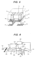
- the air flow sensor of this embodiment is provided with not only an air flow measuring element 20 but also an intake air temperature sensing element 1 which functions as an intake air temperature sensor.
- the intake air temperature sensing element 1 and the air flow measuring element 20 are mounted on a single support member 10 made of a glass-ceramic material so as to be positioned in a sub-passage 41 which is defined within an intake passage (intake pipe) 42a.
- a portion (wall portion) 41a of the passage wall is integral with a holder 40 and the remaining passage wall (wall portion) 41b is combined with the passage wall 41a to constitute the sub-passage 41.
- the support member 10 is cantilevered by the holder (air flow sensor housing) 40 which is secured to an intake pipe wall 42.
- the intake air temperature sensing element 1 is disposed at one end of the support member 10 on the side opposite to the cantilevered side and at a position away from the holder 40 with respect to the air flow measuring element 20. As shown in Fig. 3, the intake air temperature sensing element 1 is located on an upstream side in the air flow direction with respect to the air flow measuring element 20.
- the air flow measuring element 20 and the intake air temperature sensing element 1 are electrically connected at 31a and 12' to conductors 11 and 12 which are formed on the support member 10.
- the electric connections 31a and 12' are sealed with an insulating resin 2.
- the resin there is used one of an epoxy resin, a fluorine-containing resin, and a glass material.
- the support member 10 is constituted by a laminate substrate and the conductor 11 is formed on the surface of the laminate substrate. But as to the conductor 12, it is interposed between layers of the laminate substrate 10 and one end thereof is exposed to the surface of the laminate substrate 10 at the installed position of the intake air temperature sensing element 1 through a via hole 10a formed in the laminate substrate. This exposed portion of the conductor 12 corresponds to the electric connection 12'.
- the details on the connection of the intake air temperature sensing element 1 will be described later with reference to Fig. 5.
- the opposite end of the conductor 12 is electrically connected through a via hole 10b to a terminal 16 formed in a circuit section on the laminate substrate 10.
- the conductors 11 and 12 may hereinafter be sometimes designated a surface conductor and an inner conductor, respectively.
- Terminals 27 (shown in Fig. 4) of a heating resistor 22 and a heat sensing resistor 23 are electrically connected to the support member 10-side conductor 11 (terminals 91-94) each by wire bonding 31a of gold wire for example.
- the sub-passage (intake air measuring passage) 41 is cylindrical and is formed at one end (front end) of the holder 40, while at the opposite end of the holder 40 are mounted a flange 43 and a connector case 44.
- One end of a pin terminal 44a of the connector case 44 is conducted to the holder 40 and is connected through wire 31d to a terminal 16 formed on the support member 10.
- the holder 40 and the sub-passage 41 are set within the intake passage 42a through a mounting hole 45 formed in the intake pipe wall 42, and the air flow sensor 100 is secured to the intake pipe wall 42 through the flange 43.
- thermal air flow measuring element 20 will be described below with reference to Figs. 2 and 4.
- the air flow measuring element 20 is fabricated by the micromachining technique for semiconductors. More specifically, an electric insulating layer 21 is formed on a single crystal silicon substrate 28 and at least one heating resistor 22 and a temperature sensing resistor 23 are formed thereon by patterning.
- the resistor forming area corresponds to the area indicated by the reference mark S in Fig. 3.
- Below (on the back side) the area of the single crystal silicon 28 with the heating resistor 22 formed therein is formed a cavity 26 by removing the substrate 28 up to the electric insulating layer 21 in accordance with an anisotropic etching technique.
- the heating resistor 22 is insulated thermally, whereby it becomes possible to let the resistor generate heat while saving power and hence possible to effect an air flow detection utilizing the heat exchange with air flow.
- a silicon dioxide layer is formed as the electric insulating layer 21 on the single crystal silicon substrate 28 by, for example, thermal oxidation or CVD (Chemical Vapor Deposition) and thereafter a silicon nitride layer is formed by CVD for example.
- a polycrystalline silicon layer is formed by CVD for example, followed by doping of phosphorus (P) as impurity by thermal diffusion or by ion implantation.
- the heating resistor 22 and the temperature sensing resistor 23 are formed by patterning the polycrystalline silicon layer.
- a silicon nitride layer is formed as a protective layer 29 and thereafter a silicon dioxide layer is formed, both by CVD for example.
- the protective layer 29 is subjected to patterning in the same way as above to remove the protective layer portion where electrodes 27 are to be formed.
- an aluminum layer is formed and patterning is performed by etching.
- a silicon nitride layer is formed by CVD for example on the surface portion of the single crystal silicon 28 where the heating resistor 22 is not formed, followed by patterning. Thereafter, the cavity 26 is formed by anisotropic etching, followed by dicing for division into chips.
- the air flow measuring element 20 thus obtained by the division is, for example, 6 mm long by 2.5 mm wide by 0.3 mm thick.
- the support member 10 is constituted by a laminate substrate of a glass-ceramic material.
- a recess 13a for disposing the air flow measuring element 20 therein.
- the recess 13a is formed by punching a desired number of constituent layers of the laminate substrate in a green sheet state into a desired shape with use of a punching die.
- the air flow measuring element 20 is mounted within the recess 13a through an adhesive 30.
- a suitable depth of the recess 13a is determined so that the surface of the air flow measuring element 20 and that of the support member (laminate substrate) 10 become flush with each other, taking the thickness of the adhesive 30 also into account. This is because if there is a difference in height between the surface of the support member 10 and that of the air flow measuring element 20, the air flow is disturbed by such difference in height and the output characteristic becomes unstable.
- the adhesive 30 there is used an epoxy or silicon adhesive.
- a part of the back of the silicon substrate 28 is bonded to an inside bottom of the recess 13a.
- the non-bonded back portion of the silicon substrate 28 ensures a gap between it and the bottom of the recess 13a. Consequently, the heat insulating property of the substrate 10 against the heating resistor 22 is further enhanced by cooperation with the cavity 26. Also enhanced is the heat exchanging performance between the heat of the heating resistor 22 and the air flow.
- a resistance film 14 necessary for an electronic circuit related to the measurement of air flow is formed on the surface or the back of the support member 10.
- the intake air temperature sensing element 1 is used a chip-like thermistor which permits the reduction of size.
- the thermistor is formed to a size of 1.6 x 0.8 x 0.8 (mm) or 1.0 x 0.5 x 0.5 (mm) using such a material as MnO-CoO-NiO spinel or MnO-CoO spinel/ZrO 2 solid electrolyte/Al 2 O 3 -spinel composite.
- a chip mouner such a chip-like intake air temperature sensing element 1 can be mounted onto the laminate substrate 10 in the same way as and simultaneously with the thermal air flow measuring element 20.
- the intake air temperature sensing element 1 is provided at both ends thereof with electrodes 1a and 1b which are each electrically connected through solder 80 to a conductor film (electric connection) 12' formed on the surface of the support member (laminate substrate) 10.
- the conductor film 12' is connected to the inner conductor 12 in the support member 10 through a via hole 15.
- a pattern of the solder 80 can be formed, for example, by printing as is the case with other circuit components 17.
- the intake air. temperature sensing element 1 can be electrically connected to the substrate without decreasing the productivity.
- the electronic circuit section 19 is composed of such components as an IC chip 18 and resistors 17 and is sealed within the holder 40.
- the back of the support member 10 is fixed to an inner surface of the holder 40 through an adhesive 47 and its electronic circuit section 19 side is sealed with silicon gel or the like.
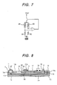
- FIG. 7 A circuit diagram related to the electronic circuit section 19 and the thermal air flow measuring element 20 is illustrated in Fig. 7. As shown in the same figure, outputs of a heating resistor 22 and a temperature sensing resistor 23 are taken out through resistors R1 and R2, and a feedback circuit is formed through an operational amplifier, whereby the heating resistor 22 is controlled so as to become higher by a predetermined certain temperature than the temperature sensing resistor 23.
- Conductors 11 on the surface and the back of the support member (laminate substrate) 10 and inner conductors 12 are connected together through via holes 15.
- the air flow measuring element 20 about 2 x 6 x 0.3 mm in size, as noted earlier, if it is disposed centrally of the sub-passage 41 as in Fig. 1, the electric connection 31a is exposed to the air in the absence of resin 2 and so is the electric connection 12' of the intake air temperature sensing element 1. It follows that the electric connection is placed in a metal corrosion inducing environment which contains moisture present in intake air, gasoline vapor, engine oil, and sulfurous acid gas present in blow-by gas. But in this embodiment there is adopted a structure wherein the electric connection is not directly exposed to intake air because it is sealed with resin. Consequently, it is possible to prevent the aforesaid corrosion.
- the portions sealed with resin 2 are formed on the support member 10 which is made of a glass-ceramic material having a low thermal conductivity and are spaced away from the holder 40 and the pipe wall of the sub-passage 41, the heat generated from the engine and also from the electronic circuit section of the air flow sensor can be prevented from being transmitted to the intake air temperature sensing element 1 and the air flow measuring element 20 through the resin.
- the resin 2 used for sealing should come into contact with a resin portion in the air flow sensor such as the holder 40, there may occur the following phenomenon.
- an environment temperature of the thermal air flow sensor varies in a wide range of -30 to 100°C or higher.
- heat of the above environment temperature is transferred to the intake air temperature sensing element through the housing of the air flow sensor, it becomes difficult for the sensing element to accurately measure the intake air temperature.
- Such an inconvenience can be prevented by adopting the foregoing structure in this embodiment.
- the air flow measuring element 20 is disposed centrally of the sub-passage 41 and the portion of the connecting wire 31a is sealed with resin 2 such as an epoxy resin, the surface of the air flow measuring element 20 becomes substantially flush with the surface of the support member 10 and the resin 20 covers the electric connection 31a and the vicinity thereof gently in a filmy form. Therefore, even if the electric connection is positioned near the wall surface of the sub-passage 41, it is possible to prevent the disturbance of intake air flow moving near the said wall surface, thus making it possible to keep the air flow measuring accuracy high.
- resin 2 such as an epoxy resin
- the sealing with resin 2 there may be adopted such a method as printing or potting.
- a method as printing or potting.
- the printing method variations in shape among sealed portions are small as compared with the potting method. Since each sealed portion is exposed to the flow of air and is located near the air flow measuring element 20, the smaller the variations in shape, the smaller the variations in air flow measurement.
- the air flow sensor 100 is placed in an environment where the temperature varies in the range of about -30 to 130°C. Therefore, in order that the intake air temperature sensing element 1 installed in the air flow sensor 100 can detect the temperature of intake air accurately, it is desirable to minimize the influence of such temperature variation. To this end it is desirable that the support member 10, which is a heat conducting path to the intake air temperature sensing element 1, be formed using a material of a low thermal conductivity.
- the thermal conductivity of the glass-ceramic substrate 10 as the support member used in the invention is about 3 5 to 4W/m ⁇ EK.
- the intake air temperature sensing element 1 is disposed on the glass-ceramic substrate (support member) 10 at a position distant from the holder 40, it is possible to. minimize the quantity of heat transmitted from the air flow sensor to the intake air temperature sensing element 1.
- the intake air temperature sensing element 1 be installed at a position where it does not disturb the flow of air on the surface of the air flow measuring element 20. To meet this requirement, it is desirable that the intake air temperature sensing element 1 be disposed at the front end, or the tip, of the support member 10 as in Fig. 1 (in other words, it is desirable to avoid overlapping of the intake air temperature sensing element 1 and the air flow measuring element 20 for the flow of air). Likewise, for preventing the intake air temperature sensing element 1 from being influenced by the heat of the air flow measuring element 20, it is desirable that the intake air temperature sensing element 1 be mounted upstream of the air flow measuring element 20.
- the cooling effect for the intake air temperature sensing element 1 is more outstanding.
- mounting the intake air temperature sensing element 1 on the support member 10 of the air flow sensor so as to be positioned in the sub-passage 41 is effective for enhancing the sensing accuracy of the intake air temperature sensing element 1.
- the intake air temperature sensing element 1 and the surface conductors 12' can be sealed with resin 2, it is possible to improve their durability to a remarkable extent. Besides, since the use of the chip-like intake air temperature sensing element 1 permits forming the sealed area in a very small size, it is possible, despite the resin sealing, to attain a performance equal to that obtained without resin sealing.
- Fig. 6 is a system diagram of an internal combustion engine such as a gasoline engine which uses the air flow sensor 100 of this embodiment.
- the air flow sensor 100 As shown in the same figure, in the intake passage 42a of an engine there are mounted the air flow sensor 100, an air cleaner 102, a throttle angle sensor 103, an idling speed control valve 104, and a throttle body 105.
- the numeral 106 denotes an intake manifold.
- Intake air 101 flowing through the intake passage 42a is measured for flow by the air flow sensor 100 in the sub-passage and the temperature thereof is detected by the intake air temperature sensing element 1.
- An air flow signal is received by a vehicular control unit 107 using voltage or frequency and so is an intake air temperature signal using voltage.
- the air flow signal is used for controlling a combustion structure composed of an injector 108, a tachometer 109, an engine cylinder 110, an exhaust manifold 111, and an oxygen sensor 112, and for controlling a subsystem.
- the intake air temperature signal As noted earlier, it is used, for example, for controlling the ignition timing, controlling the boost pressure of a turbo-charger, limiter control for fuel injection volume in a rapid acceleration, and further for judging whether the catalyst used has reached its active temperature or not.
- the support member 10 may take any of various other forms than that described in the above embodiment. Structurally, such various other forms are common in many points to the one described in the above embodiment. Reference will be made below particularly to different points.
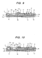
- a recess 13b is formed in the surface of the support member (laminate substrate) 10 in addition to the recess 13a which is for the air flow measuring element 20, and the intake air temperature sensing element 1 is mounted therein, whereby the height of the element 1 exposed to the surface of the laminate substrate 10 after sealing can be made low.
- the disturbance of air flow on the surface of the support member 10 is diminished, so that the disturbance of air flow on the surface of the air flow measuring element 20 is diminished and the flow measuring accuracy is improved.
- the recess 13b for the intake air temperature measuring element 1 is formed in the surface of the support member 10, but the thickness of the intake air temperature sensing element 1 is set smaller than the depth of the recess 13b, whereby the surface of the intake air temperature sensing element 1 after resin sealing can be made substantially flush with the surface of the laminate substrate 10. This is most effective in diminishing the disturbance of air flow on the surface of the support member 10.
- the recess 13b can be formed simultaneously with formation of the recess 13a for the air flow measuring element 20 and thus can be formed without impairing the productivity.
- one end 12' of an inner conductor 12 is exposed through a via hole 10a to the surface of the support member 10 around the recess 13b (the mounted position of the intake air temperature sensing element 1) formed in the support member.
- the exposed portion 12' is constituted by the conductor film formed on the surface of the support member and this conductor film 12' and the intake air temperature sensing element 1 are connected together by bonding of wire 31b such as a gold wire.
- the intake air temperature sensing element 1 is secured to the bottom of the recess 13b through the adhesive 30.
- the bonding work for the intake air temperature sensing element 1 can be done simultaneously with the bonding work for the air flow measuring element 20 and the laminate substrate surface conductor 11. Consequently, the intake air temperature sensing element 1 can be connected electrically without impairing the productivity.
- the height of the connecting wire 31b from the intake air temperature sensing element 1 can be set equal to or lower than the height of the connecting wire 31a from the air flow measuring element 20. Consequently, the height of the sealing resin 2 for the intake air temperature sensing element 1 and that for the air flow measuring element 20 can be made equal to each other.
- the electric connections 31a and 31b of the air flow measuring element 20 and the intake air temperature sensing element 1, respectively, can be resin-sealed simultaneously by the foregoing printing method, so that, as mentioned previously, variations in sealed shape are diminished and the thermal air flow sensor 100 can be produced with a high accuracy.
- the intake air temperature sensing element 1 and each surface conductor 12' formed on the support member 10 are connected together by wire bonding 31b, provided stepped surfaces are formed so that the surface of the surface conductor 12' becomes lower than the top surface of the support member 10.
- a suitable example of the sealing resin 2 is one superior in environmental resistance and in swelling resistance against non-polar solvents such as gasoline and engine oil.
- Examples include fluorine-containing resins in addition to the epoxy resins referred to earlier. Particularly, fluorine-containing resins are softer than epoxy resins even after curing and are therefore advantageous in that stresses imposed on the connecting wires 31a and 31b are smaller. However, in point of handleability after resin sealing, fluorine-containing resins are inferior to epoxy resins.
- the sensing element 1 By using the chip-like intake air temperature sensing element 1 which permits mounting in a reduced size, the sensing element 1 can be mounted to the support member 10 with scarcely any necessity of introducing new manufacturing equipment. Thus, it becomes possible to produce an air flow sensor equipped with a highly reliable intake air temperature sensing element. Particularly, in the construction shown in Fig. 10, the air flow measuring element 20 and the intake air temperature sensing element 1 can be assembled by similar assembling processes, thus making it possible to improve the productivity.
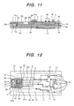
- Fig. 12 is a plan view of a support member 10 used in the sixth embodiment of the present invention, as well as an air flow measuring and intake air temperature sensing components, and Fig. 13 is a longitudinal sectional view thereof.
- the intake air temperature sensing element 1 and the air flow measuring element 20 are mounted in the recesses 13b and 13a, respectively.
- the mode of electric connection between the intake air temperature sensing element 1 and each conductor 12' on the support member 10 is the same as in the embodiment illustrated in Fig. 10.
- the recesses 13a and 13b are formed so as to be arranged in a direction perpendicular to the air flowing direction, and electrodes 91 to 96 for electric connection of the elements 1 and 20 are provided between the recesses 13a and 13b in the . surface of the support member 10.
- the air flow measuring element 20 is disposed in a direction opposite to its direction adopted in the previous embodiments, i.e., it is disposed so that its electrodes 27 face the intake air temperature sensing element 1). According to this arrangement it suffices to set only one place for sealing with resin 2, thus making it possible to further improve the productivity of the air flow sensor.
- the glass-ceramic material itself used in the previous embodiments can fully eliminate the thermal influence of the engine and the air flow sensor circuit section (including the air flow measuring element 20) upon the intake air temperature sensing element 1, but by taking various heat conduction suppressing measures as will be shown in the following embodiments it is made possible to ensure a high accuracy of the intake air temperature sensing element 1.
- a ceramic material higher in thermal conductivity than the glass-ceramic material it is possible to eliminate the aforesaid thermal influence.to a satisfactory extent.
- Fig. 14 is a partially omitted plan view showing the back of a support member 10 used in the seventh embodiment of the present invention and Fig. 15 is a longitudinal sectional view taken on line A-A in Fig. 14.
- a large number of slits 50 are formed in the back of the support member 10 to suppress the conduction of heat from the air flow sensor and the engine to the intake air temperature sensing element 1 through the support member 10. As a result, it is possible to improve the accuracy of the intake air temperature sensing element 1.
- the surface of the support member 10 be free of any concave or convex which would disturb the air flow and that therefore the slits 50 be formed on the back side of the support member 10.
- a recess 13c in the support member 10 in a position corresponding the underside of the intake air temperature sensing element 1, it is possible to diminish the influence of the thermal conduction.
- the slits 50 and the recess 13c can be formed by the same method as the method of forming the recess 13a which is for mounting the thermal air flow measuring element 20 therein, and thus can be formed without impairing the productivity.
- the slits 50 may be formed on the surface side of the support member 10 insofar as the position where they are formed does not disturb the air flow on the surface of. the air flow measuring element 20.
- slits 50 are formed in the surface of the support member 10.
- the slits are formed around the intake air temperature sensing element 1 and on the support member cantilevered side with respect to the air flow measuring element 20.
- the slits 50 be formed as through slits from the surface to the back of the support member 10.
- the same heat conduction preventing effect as above can be obtained even by forming a large number of through holes 51 in the surface of the support member 10 as in Fig. 17 which illustrates the ninth embodiment of the present invention.
- the through holes 51 can be formed simultaneously with formation of via holes 15 in the laminate substrate 10 as referred to previously.
- the stain resistance can be improved by forming the through holes 51. This is for the following reason.
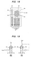
- a heating resistor 22 and a temperature sensing resistor 23 for temperature compensation constitute a feedback circuit, as shown in Fig. 19.
- the configuration of this circuit is the same as that shown in Fig. 7 to which reference has been made already.
- the heating resistor 22 is controlled so as to be higher in temperature to a certain degree relative to the temperature sensing resistor 23.
- temperature sensing resistors 24 and 25 are disposed on both sides of the heating resistor 22 so as to be positioned respectively upstream and downstream of the heating resistor.
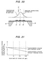
- the temperature sensing resistors 24 and 25 receive heat from the heating resistor 22 and each reach a certain temperature level. In the absence of air flow, both upstream and downstream temperature sensing resistors 24, 25 are at approximately the same temperature. This state is represented by a broken-line temperature distribution in Fig. 20.
- the temperature sensing resistor 24 located on the upstream side is cooled by the air flow and the temperature sensing resistor located on the downstream side becomes easier to receive heat from the upstream side.
- This state is represented by a solid-line temperature distribution in Fig.
- the upstream- and downstream-side temperature sensing resistors 24, 25 Since this temperature difference serves as a function of air flow, the air flow can be detected by detecting the amount of such temperature difference. More specifically, in this embodiment the upstream- and downstream-side temperature sensing resistance values vary depending on the above temperature difference, so by constituting such a bridge circuit as shown in Fig. 19 the temperature difference can be converted to a voltage difference to determine the flow of air.
- the thermal air flow measuring element 20 is of a structure wherein it is exposed to intake air, as noted earlier, a contaminant contained in the air flow is deposited on the surface of the thermal air flow measuring element 20 as a result of use over a long period. Consequently, the output characteristic of the air flow sensor 100 changes, and in the case of the thermal air flow measuring element shown in Fig. 18, a negative shift of the characteristic occurs in a high flow region, as shown in Fig. 20.
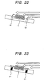
- the through holes 51 are formed, air flows also in the through holes as. in Fig. 22 in the absence of no deposited contaminant, while in the presence of deposited contaminant the through holes 51 are filled up with the contaminant as in Fig. 23, so that the air flow on the substrate surface substantially increases.
- the flow output characteristic of the air flow sensor is improved, as shown in Fig. 21.
- the support member 10 is constituted by a laminate substrate of a low thermal conductivity such as a glass-ceramic substrate, it is not always required to be a laminate substrate insofar as it is of a structure which prevents the conduction of heat from the holder (air flow sensor housing) 40 to the intake air temperature sensing element 1.
- Fig. 14 illustrates an embodiment wherein a support member 60 constituted by a single-layer substrate is used in place of the support member (laminate substrate) 10, in which (a) is a partially omitted plan view of the support member 60 as seen from above, (b) is a sectional view taken on line B-B thereof, and (c) is a sectional view taken on line c-c thereof.
- the support member 60 is also constituted using a glass-ceramic material for example.
- the recess 13a for mounting the air flow measuring element 20 the recess 13b for mounting the intake air temperature sensing element 1, as well as the foregoing slits 50 and recess 13c, can be formed using a mold.
- the material of the support member 60 is of a low thermal conductivity such as a glass-ceramic material, then by combination with heat conduction suppressing slits 50 and recess 13c, it becomes possible to produce a thermal air flow sensor with an intake air temperature sensing element of a high performance even if the intake air temperature sensing element 1 is disposed on the cantilevered side of the support member 60.
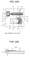
- Fig. 25 illustrates the eleventh embodiment of the present invention, in which (a) is a partially omitted plan view of a support member 60 as seen from above and (b) is a sectional view taken on line D-D thereof.
- the support member 60 used in this embodiment is also constituted by a single-layer substrate of a glass-ceramic material.
- the intake air temperature sensing element 1 it is disposed at a front end of the support member 60.
- Lead wires (conductors) 12' of the intake air temperature sensing element 1 are formed on the surface of the support member 60, but by covering the conductors 12' with glass it is made possible to enhance the corrosion resistance of the conductors, and by so doing it becomes possible to dispose the intake air temperature sensing element 1 at any position on the support member 60.
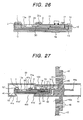
- the sensing element 1 may be constituted by a printed resistor on the support member 10 as in the embodiment illustrated in Fig. 26.
- its electric connection may be sealed with glass instead of resin 2.
- Fig. 27 is a longitudinal sectional view illustrating the thirteenth embodiment of the present invention.
- the support member 10 or the support member 60
- the support member 10 is supported at both ends thereof by both holder 40 and the wall 41a of the sub-passage 41 instead of being cantilevered by the holder 40.
- Another different point resides in that there is adopted a structure whereby both sides of a portion of the support member 10 located away from the intake pipe wall 42 are easy to be taken away their heat by the air flow moving through the intake pipe and that the air flow measuring element 20 and the intake air temperature sensing element 1 are disposed on such a heat-removed surface of the support member.
- an opening 400 is formed in the wall 41a of the sub-passage and projections 41a' and 41a" for supporting both ends of the support member 10 are formed at the edge of the opening 400.
- the support member 10 faces the interior of the intake passage 42a through the opening 400. According to this embodiment, on the mounted side of the air flow measuring element 20 and the intake air temperature sensing element 1 the support member 10 is taken away its heat by the air flow moving through the sub-passage 41, while on the opposite side the heat of the support member is taken away by the air flow moving within the intake passage 42a through the opening 400.
- Fig. 28 is a longitudinal sectional view illustrating the fourth embodiment of the present invention.
- This embodiment is different from the previous embodiments in that, as to the portion of the support member 10 positioned in the sub-passage 41, one side (opposite to the mounted side of the intake air temperature sensing element 1 and the air flow measuring element 20) is borne by an inner surface of the sub-passage wall 41a and that a heat radiating member such as a heat radiating.plate (fins) 401 is formed on an outer surface of the sub-passage wall 41a whose inner surface bears the one side of the support member 10.
- the heat of the support member 10 is taken away by the air flow moving through the sub-passage 41, while on the opposite side the heat of the support member is taken away by the air flow moving through the intake passage 42a through the heat radiating fins 401.
- the same effect as in the thirteenth embodiment can be attained.
- the outer surface of the wall 41a with the heat radiating fins 401 provided thereon is recessed inwards at 402 and the heat radiating fins 401 are fitted in the recess 402. In this way the heat radiating fins 401 are prevented from obstructing the air flow in the intake passage 42a.
- Fig. 29 is a longitudinal sectional view illustrating the fifteenth embodiment of the present invention.
- This embodiment also adopts both-end supporting structure for the support member 10, provided according to this embodiment both sides of the support member positioned in the sub-passage 41 are easy to be taken away their heat by the air flow moving through the intake pipe (sub-passage) as is the case with the embodiment illustrated in Fig. 1.
- One end of the support member is held by the holder 40, while the opposite end thereof is held by a projection 403 formed at one end of the sub-passage wall 41a.
- a portion 403' of the projection 403 which receives the front end of the support member 10 is stepped so that the stepped portion 403' can receive the support member and effect positioning thereof at the time of mounting of the support member.
- an air-cooling effect for the support member 10 can be expected and the heat of the engine from the intake pipe wall and the heat of the heating resistor can be effectively prevented from being transmitted to the intake air temperature sensing element 1.
- the intake air temperature sensing element 1 used in each of the above embodiments is one applied to an intake air temperature sensor which is to be used for a purpose different from the air flow measurement
- the temperature measuring resistor 23 for temperature compensation may be disposed on the support 10 or 60 by the same method.
- the support 10 or 60 can also be constituted by a resin substrate and the present invention is applicable also to a single-layer or laminate substrate of a resin such as a glass-epoxy, phenolic, or polyimide resin.
- the influence of heat from the thermal air flow sensor and from the engine upon the intake air temperature sensor can be suppressed to a satisfactory extent, thereby making it possible to unite the intake air temperature sensor and the thermal air flow sensor with each other. Consequently, it is possible to provide an air flow sensor capable of reducing the number of components and cost of the measurement system, capable of rationalizing the mounting work and mounting space and further capable of keeping high the accuracy of the intake air temperature sensor.
- the intake air temperature sensing element can exhibit corrosion resistance and retain its soundness even when placed in metal corrosion inducing environment containing moisture present in intake air, gasoline vapor, engine oil, sulfurous acid gas present in blow-by gas, and nitrogen oxides.
Landscapes
- Physics & Mathematics (AREA)
- Fluid Mechanics (AREA)
- General Physics & Mathematics (AREA)
- Engineering & Computer Science (AREA)
- Chemical & Material Sciences (AREA)
- Combustion & Propulsion (AREA)
- Mechanical Engineering (AREA)
- General Engineering & Computer Science (AREA)
- Measuring Volume Flow (AREA)
- Measuring Temperature Or Quantity Of Heat (AREA)
- Electrical Control Of Air Or Fuel Supplied To Internal-Combustion Engine (AREA)
Abstract
In a thermal air flow sensor, an air flow measuring
element and an intake air temperature sensing element of
an intake air temperature sensor are mounted on a single
support member so as to be positioned within an intake
passage. The support member is made of a glass-ceramic
material for example and is held by a holder secured to the
wall of an intake pipe. The support member has a structure
whereby both sides of a portion of the support member
located on the side away from the intake pipe wall are easy
to be taken away their heat by an air flow moving through
the intake pipe. The air flow measuring element and the
intake air temperature sensing element are disposed on such
a heat-removed surface of the support member and are
electrically connected respectively to conductors disposed.
on the support member, with their electric connections
being sealed with resin, whereby the intake air temperature
sensor and the air flow sensor can be rendered integral
with each other.
Description
The present invention relates to a thermal air flow
sensor (air flow meter) for measuring the air flow (the
amount of flowing) with use of a heating resistor. For
example, the invention is concerned with an air flow sensor
suitable for measuring the flow of intake air in an
internal combustion engine.
As an air flow sensor installed in an intake passage
of an internal combustion engine of an automobile or the
like, a thermal type has come to be mainly adopted because
it can detect a mass flow directly.
For example, such a thermal type air flow sensor
uses, as air flow measuring elements, a heating resistor
which makes heat exchange with intake air directly or
indirectly and a resistor which compensates a change in air
temperature at the time of measuring the air flow
(sometimes also called a temperature compensating resistor,
a thermal sensitive resistor, or a temperature measuring
resistor), and controls an electric current flowing in the
heating resistor so that a temperature difference between
the heating resistor and the temperature compensating
resistor becomes constant. This current value is converted
into an electric signal to measure the air flow.
The heating resistor and the temperature
compensating resistor have temperature dependence and for
fabricating them there recently has been proposed a method
of forming a thin film-like resistance area for air flow
measurement on a semiconductor substrate such as silicon
(Si) for example by using a micromachining technique for
semiconductor. This method can mass-produce thermal air
flow sensors relatively easily and is economical, so is now
attracting attention as an air flow sensor capable of being
driven with low electric power.
A semiconductor type air flow measuring device is
disclosed, for example, in Japanese Patent Laid Open
(Tokuhyo) No. 9-503310. According to the conventional
technique disclosed in this publication, in a mass
measuring apparatus for measuring an intake mass of an
internal combustion engine, a sensor element is formed by
etching a silicon wafer for example to form a diaphragm-like
sensor region and forming plural resistance layers
(one is a measuring resistor having temperature dependence
and another is a heating resistor for heating the measuring
resistor). As to a medium temperature resistance for
compensating the temperature of a fluid medium, it is
disposed on an outer surface of a casing of the mass
measuring apparatus in order to avoid a thermal influence
of the heating resistor.
According to another conventional technique, as
disclosed, for example, in Japanese Patent Laid Open No.
2000-28411, a flow sensing section formed with a heating
element and a temperature sensing element for flow
measurement which is heated by the heating element, as well
as a temperature sensing section formed with a temperature
sensing element which makes air temperature compensation
for flow measurement, are formed at one end of a substrate
such as a silicon, alumina or glass substrate, and part of
the substrate and output terminals are covered with a cover
member by molding. In this conventional technique it is
proposed to form a slit between the flow sensing section
and the temperature sensing section for preventing the
temperature sensing section from being thermally influenced
by the flow sensing section.
In the thermal air flow sensor, as referred to above,
a heating resistor and a temperature compensating resistor
are used as air flow measuring elements.
In connection with an internal combustion engine,
the supply of fuel is controlled in accordance with the
value of air flow, but attempts have been made to utilize
the intake air temperature in various automobile controls
with use of an intake air temperature sensor. Examples
include ignition timing control, boost pressure control for
a turbo-charger, limiter control for fuel injection volume
in rapid acceleration, and judgment as to whether the
catalyst used has reached an active catalyst temperature.
It is an object of the present invention to provide
an air flow sensor capable of being rendered integral with
an intake air temperature sensor, thereby capable of
attaining the reduction in the number of sensor components,
reduction of cost and rationalization of the mounting work
and mounting space, and further capable of keeping high the
accuracy of the intake air temperature sensor.
It is another object of the present invention to
provide a thermal air flow sensor which, even when an
intake air temperature sensing element (the type of use
does not matter specially) and a thermal air flow measuring
element are mounted on a common support member in case of
uniting the intake air temperature sensing element with the
air flow sensor, can fully eliminate a thermal influence
from a heating resistor and circuit section of the air flow
measuring element and from an engine. Therefore it is to
provide a thermal air flow sensor which can enhance the
intake air temperature measurement accuracy and which can
maintain the soundness of the intake air temperature
sensing element even when placed in a metal corrosion
inducing environment containing moisture present in the
intake air, gasoline vapor, engine oil, and sulfurous acid
gas and nitrogen oxides present in blow-by gas.
According to the present invention, for achieving
the above-mentioned objects, there basically is provided a
thermal air flow sensor having a thermal element for
measuring the air flow flowing through an intake passage,
the thermal air flow measuring element having a heating
resistor and being disposed within the intake passage,
wherein an intake air temperature sensing element used in
an intake air temperature sensor is mounted on a single
support member made of a glass-ceramic material etc
together with the air flow measuring element and is
positioned within the intake passage. Moreover, the air
flow measuring element and the intake air temperature
sensing element are electrically connected respectively to
conductors disposed on the support member and the resulting
electric connections are sealed with resin.
According to the present invention, moreover, there
is adopted a structure wherein both sides of a portion of
the support member located on the side apart from the wall
of an intake pipe are easy to be taken away their heat by
an air flow moving through the intake pipe. On such a
heat-removed substrate side there are provided the air flow
measuring element and the intake air temperature sensing
element.
The present invention further proposes the following
thermal air flow sensors.
One is a thermal air flow sensor having an intake
air temperature sensing element, wherein this intake air
temperature sensing element and the foregoing air flow
measuring element are mounted on a single glass-ceramic or
ceramic support member and are positioned within the intake
passage, the support member is cantilevered by means of a
holder attached to the wall of the intake pipe, and the
intake air temperature sensing element is disposed at one
end of the support member on the side opposite to the
cantilevered side and at a position away from the holder
with respect to the air flow measuring element. The air
flow measuring element and the intake air temperature
sensing element are electrically connected respectively to
conductors disposed on the support member and the resulting
electric connections are sealed with resin.
Another is a thermal air flow sensor having a
structure whereby both sides of a portion of the support
member located on the side away from the wall of the intake
pipe are easy to be taken away their heat by an air flow
moving through the intake pipe. On such a heat-removed
support member side there are disposed the air flow
measuring element and the intake air temperature sensing
element.
A still another is a thermal air flow sensor wherein
the air flow measuring element and the intake air
temperature sensing element are respectively mounted in
recesses formed each individually in the support member and
are electrically connected respectively to conductors
disposed on the support member. The resulting electric
connections are sealed with resin.
Embodiments of the present invention will be
described hereinunder with reference to the accompanying
drawings.
Description will be directed first to a thermal air
flow sensor according to the first embodiment of the
present invention.
As shown in Fig. 1, the air flow sensor of this
embodiment, indicated at 100, is provided with not only an
air flow measuring element 20 but also an intake air
temperature sensing element 1 which functions as an intake
air temperature sensor. The intake air temperature sensing
element 1 and the air flow measuring element 20 are mounted
on a single support member 10 made of a glass-ceramic
material so as to be positioned in a sub-passage 41 which
is defined within an intake passage (intake pipe) 42a.
In the sub-passage 41, a portion (wall portion) 41a
of the passage wall is integral with a holder 40 and the
remaining passage wall (wall portion) 41b is combined with
the passage wall 41a to constitute the sub-passage 41.
The support member 10 is cantilevered by the holder
(air flow sensor housing) 40 which is secured to an intake
pipe wall 42. The intake air temperature sensing element 1
is disposed at one end of the support member 10 on the side
opposite to the cantilevered side and at a position away
from the holder 40 with respect to the air flow measuring
element 20. As shown in Fig. 3, the intake air temperature
sensing element 1 is located on an upstream side in the air
flow direction with respect to the air flow measuring
element 20.
As shown in Figs. 2 and 3, the air flow measuring
element 20 and the intake air temperature sensing element 1
are electrically connected at 31a and 12' to conductors 11
and 12 which are formed on the support member 10. The
electric connections 31a and 12' are sealed with an
insulating resin 2. As the resin there is used one of an
epoxy resin, a fluorine-containing resin, and a glass
material.
In this embodiment, as will be described in more
detail later, the support member 10 is constituted by a
laminate substrate and the conductor 11 is formed on the
surface of the laminate substrate. But as to the conductor
12, it is interposed between layers of the laminate
substrate 10 and one end thereof is exposed to the surface
of the laminate substrate 10 at the installed position of
the intake air temperature sensing element 1 through a via
hole 10a formed in the laminate substrate. This exposed
portion of the conductor 12 corresponds to the electric
connection 12'. The details on the connection of the
intake air temperature sensing element 1 will be described
later with reference to Fig. 5.
The opposite end of the conductor 12 is electrically
connected through a via hole 10b to a terminal 16 formed in
a circuit section on the laminate substrate 10. The
conductors 11 and 12 may hereinafter be sometimes
designated a surface conductor and an inner conductor,
respectively.
Terminals 27 (shown in Fig. 4) of a heating resistor
22 and a heat sensing resistor 23 are electrically
connected to the support member 10-side conductor 11
(terminals 91-94) each by wire bonding 31a of gold wire for
example.
The sub-passage (intake air measuring passage) 41 is
cylindrical and is formed at one end (front end) of the
holder 40, while at the opposite end of the holder 40 are
mounted a flange 43 and a connector case 44. An area S
(Fig. 3) of the support member 10 where the air flow
measuring element 20 and the intake air temperature sensing
element 1 are provided faces the interior of the sub-passage
41. One end of a pin terminal 44a of the connector
case 44 is conducted to the holder 40 and is connected
through wire 31d to a terminal 16 formed on the support
member 10.
The holder 40 and the sub-passage 41 are set within
the intake passage 42a through a mounting hole 45 formed in
the intake pipe wall 42, and the air flow sensor 100 is
secured to the intake pipe wall 42 through the flange 43.
Now, the thermal air flow measuring element 20 will
be described below with reference to Figs. 2 and 4.
The air flow measuring element 20 is fabricated by
the micromachining technique for semiconductors. More
specifically, an electric insulating layer 21 is formed on
a single crystal silicon substrate 28 and at least one
heating resistor 22 and a temperature sensing resistor 23
are formed thereon by patterning. The resistor forming
area corresponds to the area indicated by the reference
mark S in Fig. 3. Below (on the back side) the area of the
single crystal silicon 28 with the heating resistor 22
formed therein is formed a cavity 26 by removing the
substrate 28 up to the electric insulating layer 21 in
accordance with an anisotropic etching technique.
According to such a structure, the heating resistor 22 is
insulated thermally, whereby it becomes possible to let the
resistor generate heat while saving power and hence
possible to effect an air flow detection utilizing the heat
exchange with air flow.
The following description is now provided about a
manufacturing process for the air flow measuring element 20.
A silicon dioxide layer is formed as the electric
insulating layer 21 on the single crystal silicon substrate
28 by, for example, thermal oxidation or CVD (Chemical
Vapor Deposition) and thereafter a silicon nitride layer is
formed by CVD for example. Next, a polycrystalline silicon
layer is formed by CVD for example, followed by doping of
phosphorus (P) as impurity by thermal diffusion or by ion
implantation. Thereafter, the heating resistor 22 and the
temperature sensing resistor 23 are formed by patterning
the polycrystalline silicon layer.
Next, a silicon nitride layer is formed as a
protective layer 29 and thereafter a silicon dioxide layer
is formed, both by CVD for example. Subsequently, the
protective layer 29 is subjected to patterning in the same
way as above to remove the protective layer portion where
electrodes 27 are to be formed. Then, an aluminum layer is
formed and patterning is performed by etching. Lastly, for
forming the cavity 26, a silicon nitride layer is formed by
CVD for example on the surface portion of the single
crystal silicon 28 where the heating resistor 22 is not
formed, followed by patterning. Thereafter, the cavity 26
is formed by anisotropic etching, followed by dicing for
division into chips. The air flow measuring element 20
thus obtained by the division is, for example, 6 mm long by
2.5 mm wide by 0.3 mm thick.
Reference will be made below to the process for
fabricating the laminate substrate serving as the support
member 10. In this example, the support member 10 is
constituted by a laminate substrate of a glass-ceramic
material.
First, a desired number of glass-ceramic sheets
about 0.1 to 0.3 mm thick, which are in a state of green
sheets, are laminated together in close contact with one
another under the application of pressure. In the surface
of the support member 10 is formed a recess 13a for
disposing the air flow measuring element 20 therein. The
recess 13a is formed by punching a desired number of
constituent layers of the laminate substrate in a green
sheet state into a desired shape with use of a punching die.
The air flow measuring element 20 is mounted within
the recess 13a through an adhesive 30. A suitable depth of
the recess 13a is determined so that the surface of the air
flow measuring element 20 and that of the support member
(laminate substrate) 10 become flush with each other,
taking the thickness of the adhesive 30 also into account.
This is because if there is a difference in height between
the surface of the support member 10 and that of the air
flow measuring element 20, the air flow is disturbed by
such difference in height and the output characteristic
becomes unstable. As the adhesive 30 there is used an
epoxy or silicon adhesive.
Using the adhesive, a part of the back of the
silicon substrate 28 is bonded to an inside bottom of the
recess 13a. The non-bonded back portion of the silicon
substrate 28 ensures a gap between it and the bottom of the
recess 13a. Consequently, the heat insulating property of
the substrate 10 against the heating resistor 22 is further
enhanced by cooperation with the cavity 26. Also enhanced
is the heat exchanging performance between the heat of the
heating resistor 22 and the air flow.
Where required, a resistance film 14 necessary for
an electronic circuit related to the measurement of air
flow is formed on the surface or the back of the support
member 10.
As the intake air temperature sensing element 1 is
used a chip-like thermistor which permits the reduction of
size. For example, the thermistor is formed to a size of
1.6 x 0.8 x 0.8 (mm) or 1.0 x 0.5 x 0.5 (mm) using such a
material as MnO-CoO-NiO spinel or MnO-CoO spinel/ZrO2 solid
electrolyte/Al2O3-spinel composite. Using a chip mouner,
such a chip-like intake air temperature sensing element 1
can be mounted onto the laminate substrate 10 in the same
way as and simultaneously with the thermal air flow
measuring element 20.
As shown in Fig. 5, the intake air temperature
sensing element 1 is provided at both ends thereof with
electrodes 1a and 1b which are each electrically connected
through solder 80 to a conductor film (electric connection)
12' formed on the surface of the support member (laminate
substrate) 10. As noted earlier, the conductor film 12' is
connected to the inner conductor 12 in the support member
10 through a via hole 15. A pattern of the solder 80 can
be formed, for example, by printing as is the case with
other circuit components 17. Thus, the intake air.
temperature sensing element 1 can be electrically connected
to the substrate without decreasing the productivity.
On one side of the support member 10, on the side
cantilevered by the holder 40, there is formed an
electronic circuit section 19 related to the measurement of
air flow. The electronic circuit section 19 is composed of
such components as an IC chip 18 and resistors 17 and is
sealed within the holder 40.
The back of the support member 10 is fixed to an
inner surface of the holder 40 through an adhesive 47 and
its electronic circuit section 19 side is sealed with
silicon gel or the like.
A circuit diagram related to the electronic circuit
section 19 and the thermal air flow measuring element 20 is
illustrated in Fig. 7. As shown in the same figure,
outputs of a heating resistor 22 and a temperature sensing
resistor 23 are taken out through resistors R1 and R2, and
a feedback circuit is formed through an operational
amplifier, whereby the heating resistor 22 is controlled so
as to become higher by a predetermined certain temperature
than the temperature sensing resistor 23.
Since the air flow measuring element 20 about 2 x 6
x 0.3 mm in size, as noted earlier, if it is disposed
centrally of the sub-passage 41 as in Fig. 1, the electric
connection 31a is exposed to the air in the absence of
resin 2 and so is the electric connection 12' of the intake
air temperature sensing element 1. It follows that the
electric connection is placed in a metal corrosion inducing
environment which contains moisture present in intake air,
gasoline vapor, engine oil, and sulfurous acid gas present
in blow-by gas. But in this embodiment there is adopted a
structure wherein the electric connection is not directly
exposed to intake air because it is sealed with resin.
Consequently, it is possible to prevent the aforesaid
corrosion.
Besides, since the portions sealed with resin 2 are
formed on the support member 10 which is made of a glass-ceramic
material having a low thermal conductivity and are
spaced away from the holder 40 and the pipe wall of the
sub-passage 41, the heat generated from the engine and also
from the electronic circuit section of the air flow sensor
can be prevented from being transmitted to the intake air
temperature sensing element 1 and the air flow measuring
element 20 through the resin.
If the resin 2 used for sealing should come into
contact with a resin portion in the air flow sensor such as
the holder 40, there may occur the following phenomenon.
For example, in case of starting the engine of automobile
after having been left standing in a severe district or in
the case where an automobile is driven continuously in a
high-temperature district, an environment temperature of
the thermal air flow sensor varies in a wide range of -30
to 100°C or higher. At this time, if heat of the above
environment temperature is transferred to the intake air
temperature sensing element through the housing of the air
flow sensor, it becomes difficult for the sensing element
to accurately measure the intake air temperature. Such an
inconvenience can be prevented by adopting the foregoing
structure in this embodiment.
If the air flow measuring element 20 is disposed
centrally of the sub-passage 41 and the portion of the
connecting wire 31a is sealed with resin 2 such as an epoxy
resin, the surface of the air flow measuring element 20
becomes substantially flush with the surface of the support
member 10 and the resin 20 covers the electric connection
31a and the vicinity thereof gently in a filmy form.
Therefore, even if the electric connection is positioned
near the wall surface of the sub-passage 41, it is possible
to prevent the disturbance of intake air flow moving near
the said wall surface, thus making it possible to keep the
air flow measuring accuracy high.
For the sealing with resin 2 there may be adopted
such a method as printing or potting. In the printing
method, variations in shape among sealed portions are small
as compared with the potting method. Since each sealed
portion is exposed to the flow of air and is located near
the air flow measuring element 20, the smaller the
variations in shape, the smaller the variations in air flow
measurement.
As noted earlier, due to the influence of a change
in environment temperature of the engine, the air flow
sensor 100 is placed in an environment where the
temperature varies in the range of about -30 to 130°C.
Therefore, in order that the intake air temperature sensing
element 1 installed in the air flow sensor 100 can detect
the temperature of intake air accurately, it is desirable
to minimize the influence of such temperature variation.
To this end it is desirable that the support member 10,
which is a heat conducting path to the intake air
temperature sensing element 1, be formed using a material
of a low thermal conductivity. The thermal conductivity of
the glass-ceramic substrate 10 as the support member used
in the invention is about 3 5 to 4W/m·EK. In this
connection, reference is made to the thermal conductivity
of an ordinary ceramic substrate, which is about 21W/m·EK,
and that of stainless steel, which is about 15W/m·EK. Thus,
the structure of mounting the intake air temperature
sensing element 1 onto the glass-ceramic substrate 10 is
very effective.
Particularly in this embodiment, since the intake
air temperature sensing element 1 is disposed on the glass-ceramic
substrate (support member) 10 at a position distant
from the holder 40, it is possible to. minimize the quantity
of heat transmitted from the air flow sensor to the intake
air temperature sensing element 1.
It is necessary that the intake air temperature
sensing element 1 be installed at a position where it does
not disturb the flow of air on the surface of the air flow
measuring element 20. To meet this requirement, it is
desirable that the intake air temperature sensing element 1
be disposed at the front end, or the tip, of the support
member 10 as in Fig. 1 (in other words, it is desirable to
avoid overlapping of the intake air temperature sensing
element 1 and the air flow measuring element 20 for the
flow of air). Likewise, for preventing the intake air
temperature sensing element 1 from being influenced by the
heat of the air flow measuring element 20, it is desirable
that the intake air temperature sensing element 1 be
mounted upstream of the air flow measuring element 20.
In case of disposing the intake air temperature
sensing element 1 at the front end portion of the support
member 10, it is required that a wiring space between
electrodes 16 located at the opposite-side end portion and
the intake air temperature sensing element 1 be ensured
without increasing the surface area of the support member
10. But this requirement can be satisfied by using the
inner conductors 12 as in this embodiment, which conductors
constitute a characteristic feature of the laminate
substrate 10.
Further, since air flows at a velocity higher in the
interior of the sub-passage 41 than in the main intake
passage 42a, the cooling effect for the intake air
temperature sensing element 1 is more outstanding. Thus,
mounting the intake air temperature sensing element 1 on
the support member 10 of the air flow sensor so as to be
positioned in the sub-passage 41 is effective for enhancing
the sensing accuracy of the intake air temperature sensing
element 1.
As referred to previously, since the intake air
temperature sensing element 1 and the surface conductors
12' can be sealed with resin 2, it is possible to improve
their durability to a remarkable extent. Besides, since
the use of the chip-like intake air temperature sensing
element 1 permits forming the sealed area in a very small
size, it is possible, despite the resin sealing, to attain
a performance equal to that obtained without resin sealing.
Fig. 6 is a system diagram of an internal combustion
engine such as a gasoline engine which uses the air flow
sensor 100 of this embodiment.
As shown in the same figure, in the intake passage
42a of an engine there are mounted the air flow sensor 100,
an air cleaner 102, a throttle angle sensor 103, an idling
speed control valve 104, and a throttle body 105. The
numeral 106 denotes an intake manifold.
The air flow signal is used for controlling a
combustion structure composed of an injector 108, a
tachometer 109, an engine cylinder 110, an exhaust manifold
111, and an oxygen sensor 112, and for controlling a subsystem.
As to the intake air temperature signal, as noted
earlier, it is used, for example, for controlling the
ignition timing, controlling the boost pressure of a turbo-charger,
limiter control for fuel injection volume in a
rapid acceleration, and further for judging whether the
catalyst used has reached its active temperature or not.
Also in the case of a diesel engine system, though
not shown, its basic construction is almost the same as .
that of the gasoline system and therefore the thermal air
flow sensor according to the present invention can be
applied thereto.
The support member 10 may take any of various other
forms than that described in the above embodiment.
Structurally, such various other forms are common in many
points to the one described in the above embodiment.
Reference will be made below particularly to different
points.
In the second embodiment illustrated in Fig. 8, a
recess 13b is formed in the surface of the support member
(laminate substrate) 10 in addition to the recess 13a which
is for the air flow measuring element 20, and the intake
air temperature sensing element 1 is mounted therein,
whereby the height of the element 1 exposed to the surface
of the laminate substrate 10 after sealing can be made low.
According to the above structure, the disturbance of
air flow on the surface of the support member 10 is
diminished, so that the disturbance of air flow on the
surface of the air flow measuring element 20 is diminished
and the flow measuring accuracy is improved.
In the third embodiment illustrated in Fig. 9, like
the embodiment illustrated in Fig. 8, the recess 13b for
the intake air temperature measuring element 1 is formed in
the surface of the support member 10, but the thickness of
the intake air temperature sensing element 1 is set smaller
than the depth of the recess 13b, whereby the surface of
the intake air temperature sensing element 1 after resin
sealing can be made substantially flush with the surface of
the laminate substrate 10. This is most effective in
diminishing the disturbance of air flow on the surface of
the support member 10. The recess 13b can be formed
simultaneously with formation of the recess 13a for the air
flow measuring element 20 and thus can be formed without
impairing the productivity.
As shown in Figs. 8 and 9, at the time of mounting
the intake air temperature sensing element 1 into the
recess 13b there arises a difference in height from the
soldered surface portions (surface conductors) which are
for mounting other circuit components such as components 17
and 18, thus making it difficult to form a solder pattern
of the intake air temperature sensing element 1
simultaneously with formation of solder patters of such
circuit components 17 and 18. But this can be remedied by
such a structure as illustrated in Fig. 10.
In the fourth embodiment illustrated in Fig. 10, one
end 12' of an inner conductor 12 is exposed through a via
hole 10a to the surface of the support member 10 around the
recess 13b (the mounted position of the intake air
temperature sensing element 1) formed in the support member.
The exposed portion 12' is constituted by the conductor
film formed on the surface of the support member and this
conductor film 12' and the intake air temperature sensing
element 1 are connected together by bonding of wire 31b
such as a gold wire. The intake air temperature sensing
element 1 is secured to the bottom of the recess 13b
through the adhesive 30.
By so doing, the foregoing problem related to the
formation of a solder pattern can be solved; besides, the
bonding work for the intake air temperature sensing element
1 can be done simultaneously with the bonding work for the
air flow measuring element 20 and the laminate substrate
surface conductor 11. Consequently, the intake air
temperature sensing element 1 can be connected electrically
without impairing the productivity.
In the case where the surface of the intake air
temperature sensing element 1 is flush with or lower than
the surface of the air flow measuring element 20, the
height of the connecting wire 31b from the intake air
temperature sensing element 1 can be set equal to or lower
than the height of the connecting wire 31a from the air
flow measuring element 20. Consequently, the height of the
sealing resin 2 for the intake air temperature sensing
element 1 and that for the air flow measuring element 20
can be made equal to each other.
In this case, the electric connections 31a and 31b
of the air flow measuring element 20 and the intake air
temperature sensing element 1, respectively, can be resin-sealed
simultaneously by the foregoing printing method, so
that, as mentioned previously, variations in sealed shape
are diminished and the thermal air flow sensor 100 can be
produced with a high accuracy.
Also in the fifth embodiment illustrated in Fig. 11,
the intake air temperature sensing element 1 and each
surface conductor 12' formed on the support member 10 are
connected together by wire bonding 31b, provided stepped
surfaces are formed so that the surface of the surface
conductor 12' becomes lower than the top surface of the
support member 10. By so doing, it becomes possible to
position the wire bonding 31b within the recess 13b, and
the surface of the resin 2 which seals the wire bonding
portion (electric connection) can be made substantially
flush with the surface of the laminate substrate 10.
A suitable example of the sealing resin 2 is one
superior in environmental resistance and in swelling
resistance against non-polar solvents such as gasoline and
engine oil. Examples include fluorine-containing resins in
addition to the epoxy resins referred to earlier.
Particularly, fluorine-containing resins are softer than
epoxy resins even after curing and are therefore
advantageous in that stresses imposed on the connecting
wires 31a and 31b are smaller. However, in point of
handleability after resin sealing, fluorine-containing
resins are inferior to epoxy resins.
By using the chip-like intake air temperature
sensing element 1 which permits mounting in a reduced size,
the sensing element 1 can be mounted to the support member
10 with scarcely any necessity of introducing new
manufacturing equipment. Thus, it becomes possible to
produce an air flow sensor equipped with a highly reliable
intake air temperature sensing element. Particularly, in
the construction shown in Fig. 10, the air flow measuring
element 20 and the intake air temperature sensing element 1
can be assembled by similar assembling processes, thus
making it possible to improve the productivity.
Fig. 12 is a plan view of a support member 10 used
in the sixth embodiment of the present invention, as well
as an air flow measuring and intake air temperature sensing
components, and Fig. 13 is a longitudinal sectional view
thereof.
Also in this embodiment, the intake air temperature
sensing element 1 and the air flow measuring element 20 are
mounted in the recesses 13b and 13a, respectively. The
mode of electric connection between the intake air
temperature sensing element 1 and each conductor 12' on the
support member 10 is the same as in the embodiment
illustrated in Fig. 10.
in this embodiment, moreover, electric connections
31b and 31a of the intake air temperature sensing element 1
and the air flow measuring element 20, respectively,
arranged on the support member 10 so as to gather in one
place and are together sealed with resin 2.
According to the above structure, the recesses 13a
and 13b are formed so as to be arranged in a direction
perpendicular to the air flowing direction, and electrodes
91 to 96 for electric connection of the elements 1 and 20
are provided between the recesses 13a and 13b in the .
surface of the support member 10. Further, the air flow
measuring element 20 is disposed in a direction opposite to
its direction adopted in the previous embodiments, i.e., it
is disposed so that its electrodes 27 face the intake air
temperature sensing element 1). According to this
arrangement it suffices to set only one place for sealing
with resin 2, thus making it possible to further improve
the productivity of the air flow sensor.
For measuring the intake air temperature accurately
it is desirable to minimize the influence of heat of the
engine and the air flow sensor circuit section 19 upon the
intake air temperature sensing element 1 through the
support member 10.
As the material of the support member 10, the glass-ceramic
material itself used in the previous embodiments
can fully eliminate the thermal influence of the engine and
the air flow sensor circuit section (including the air flow
measuring element 20) upon the intake air temperature
sensing element 1, but by taking various heat conduction
suppressing measures as will be shown in the following
embodiments it is made possible to ensure a high accuracy
of the intake air temperature sensing element 1. Although
in the following embodiments there is used a ceramic
material higher in thermal conductivity than the glass-ceramic
material, it is possible to eliminate the aforesaid
thermal influence.to a satisfactory extent.
Fig. 14 is a partially omitted plan view showing the
back of a support member 10 used in the seventh embodiment
of the present invention and Fig. 15 is a longitudinal
sectional view taken on line A-A in Fig. 14.
In this embodiment, a large number of slits 50 are
formed in the back of the support member 10 to suppress the
conduction of heat from the air flow sensor and the engine
to the intake air temperature sensing element 1 through the
support member 10. As a result, it is possible to improve
the accuracy of the intake air temperature sensing element
1.
It is preferable that the surface of the support
member 10 be free of any concave or convex which would
disturb the air flow and that therefore the slits 50 be
formed on the back side of the support member 10. Likewise,
by forming a recess 13c in the support member 10 in a
position corresponding the underside of the intake air
temperature sensing element 1, it is possible to diminish
the influence of the thermal conduction. The slits 50 and
the recess 13c can be formed by the same method as the
method of forming the recess 13a which is for mounting the
thermal air flow measuring element 20 therein, and thus can
be formed without impairing the productivity.
The slits 50 may be formed on the surface side of
the support member 10 insofar as the position where they
are formed does not disturb the air flow on the surface of.
the air flow measuring element 20. In a support member 10
used in the eighth embodiment illustrated in Fig. 16, slits
50 are formed in the surface of the support member 10. The
slits are formed around the intake air temperature sensing
element 1 and on the support member cantilevered side with
respect to the air flow measuring element 20.
For obtaining a more outstanding heat conduction preventing
effect it is preferable that the slits 50 be formed as
through slits from the surface to the back of the support
member 10.
The same heat conduction preventing effect as above
can be obtained even by forming a large number of through
holes 51 in the surface of the support member 10 as in Fig.
17 which illustrates the ninth embodiment of the present
invention. The through holes 51 can be formed
simultaneously with formation of via holes 15 in the
laminate substrate 10 as referred to previously. In the
case of a thermal air flow measuring element 20 shown in
Fig. 17, the stain resistance can be improved by forming
the through holes 51. This is for the following reason.
A description will be given first about the thermal
air flow measuring element 20 with reference to Fig. 18.
In this embodiment, a heating resistor 22 and a temperature
sensing resistor 23 for temperature compensation constitute
a feedback circuit, as shown in Fig. 19. The configuration
of this circuit is the same as that shown in Fig. 7 to
which reference has been made already. The heating
resistor 22 is controlled so as to be higher in temperature
to a certain degree relative to the temperature sensing
resistor 23.
In this embodiment, moreover, temperature sensing
resistors 24 and 25 are disposed on both sides of the
heating resistor 22 so as to be positioned respectively
upstream and downstream of the heating resistor. The
temperature sensing resistors 24 and 25 receive heat from
the heating resistor 22 and each reach a certain
temperature level. In the absence of air flow, both
upstream and downstream temperature sensing resistors 24,
25 are at approximately the same temperature. This state
is represented by a broken-line temperature distribution in
Fig. 20. On the other hand, in the presence of air flow,
the temperature sensing resistor 24 located on the upstream
side is cooled by the air flow and the temperature sensing
resistor located on the downstream side becomes easier to
receive heat from the upstream side. This state is
represented by a solid-line temperature distribution in Fig.
20, in which there arises a temperature difference between
the upstream- and downstream-side temperature sensing
resistors 24, 25. Since this temperature difference serves
as a function of air flow, the air flow can be detected by
detecting the amount of such temperature difference. More
specifically, in this embodiment the upstream- and
downstream-side temperature sensing resistance values vary
depending on the above temperature difference, so by
constituting such a bridge circuit as shown in Fig. 19 the
temperature difference can be converted to a voltage
difference to determine the flow of air.
In this connection, since the thermal air flow
measuring element 20 is of a structure wherein it is
exposed to intake air, as noted earlier, a contaminant
contained in the air flow is deposited on the surface of
the thermal air flow measuring element 20 as a result of
use over a long period. Consequently, the output
characteristic of the air flow sensor 100 changes, and in
the case of the thermal air flow measuring element shown in
Fig. 18, a negative shift of the characteristic occurs in a
high flow region, as shown in Fig. 20.
This is presumed to be because the amount of heat
transmitted from the heating resistor 22 to the temperature
sensing resistors 24 and 25 increases due to the deposition
of contaminant and the amount of heat transmitted from the
temperature sensing resistors 24 and 25 to air decreases,
thus making the occurrence of a temperature difference
difficult.
If the through holes 51 are formed, air flows also
in the through holes as. in Fig. 22 in the absence of no
deposited contaminant, while in the presence of deposited
contaminant the through holes 51 are filled up with the
contaminant as in Fig. 23, so that the air flow on the
substrate surface substantially increases. Thus, even with
contaminant deposited on the air flow measuring element 20,
the flow output characteristic of the air flow sensor is
improved, as shown in Fig. 21.
Although in each of the above embodiments the
support member 10 is constituted by a laminate substrate of
a low thermal conductivity such as a glass-ceramic
substrate, it is not always required to be a laminate
substrate insofar as it is of a structure which prevents
the conduction of heat from the holder (air flow sensor
housing) 40 to the intake air temperature sensing element 1.
Fig. 14 illustrates an embodiment wherein a support
member 60 constituted by a single-layer substrate is used
in place of the support member (laminate substrate) 10, in
which (a) is a partially omitted plan view of the support
member 60 as seen from above, (b) is a sectional view taken
on line B-B thereof, and (c) is a sectional view taken on
line c-c thereof.
The support member 60 is also constituted using a
glass-ceramic material for example.
In this case, the recess 13a for mounting the air
flow measuring element 20, the recess 13b for mounting the
intake air temperature sensing element 1, as well as the
foregoing slits 50 and recess 13c, can be formed using a
mold.
If the material of the support member 60 is of a low
thermal conductivity such as a glass-ceramic material, then
by combination with heat conduction suppressing slits 50
and recess 13c, it becomes possible to produce a thermal
air flow sensor with an intake air temperature sensing
element of a high performance even if the intake air
temperature sensing element 1 is disposed on the
cantilevered side of the support member 60.
Fig. 25 illustrates the eleventh embodiment of the
present invention, in which (a) is a partially omitted plan
view of a support member 60 as seen from above and (b) is a
sectional view taken on line D-D thereof.
The support member 60 used in this embodiment is
also constituted by a single-layer substrate of a glass-ceramic
material. As to the intake air temperature sensing
element 1, it is disposed at a front end of the support
member 60. Lead wires (conductors) 12' of the intake air
temperature sensing element 1 are formed on the surface of
the support member 60, but by covering the conductors 12'
with glass it is made possible to enhance the corrosion
resistance of the conductors, and by so doing it becomes
possible to dispose the intake air temperature sensing
element 1 at any position on the support member 60.
Although in each of the above embodiments a chip-like
thermistor is used as the intake air temperature
sensing element 1, the sensing element 1 may be constituted
by a printed resistor on the support member 10 as in the
embodiment illustrated in Fig. 26. In case of the sensing
element 1 being constituted by such a printed resistor, its
electric connection may be sealed with glass instead of
resin 2.
Fig. 27 is a longitudinal sectional view
illustrating the thirteenth embodiment of the present
invention.
One different point of this embodiment from the above previous embodiments resides in that the support member 10 (or the support member 60) is supported at both ends thereof by bothholder 40 and the wall 41a of the sub-passage
41 instead of being cantilevered by the holder 40.
Another different point resides in that there is adopted a
structure whereby both sides of a portion of the support
member 10 located away from the intake pipe wall 42 are
easy to be taken away their heat by the air flow moving
through the intake pipe and that the air flow measuring
element 20 and the intake air temperature sensing element 1
are disposed on such a heat-removed surface of the support
member.
One different point of this embodiment from the above previous embodiments resides in that the support member 10 (or the support member 60) is supported at both ends thereof by both
In this embodiment, an opening 400 is formed in the
wall 41a of the sub-passage and projections 41a' and 41a"
for supporting both ends of the support member 10 are
formed at the edge of the opening 400. On the side
opposite to the side where the air flow measuring element
20 and the intake air temperature sensing element 1 are
disposed the support member 10 faces the interior of the
intake passage 42a through the opening 400. According to
this embodiment, on the mounted side of the air flow
measuring element 20 and the intake air temperature sensing
element 1 the support member 10 is taken away its heat by
the air flow moving through the sub-passage 41, while on
the opposite side the heat of the support member is taken
away by the air flow moving within the intake passage 42a
through the opening 400.
As result, despite the structure wherein the support
member 10 is supported by both ends thereof by the holder
and the support passage wall, a satisfactory air-cooling
effect for the support member 10 can be expected and the
heat of the engine from the intake pipe wall and the heat
of the heating resistor can be prevented from being
transmitted to the intake air temperature sensing element 1.
Fig. 28 is a longitudinal sectional view
illustrating the fourth embodiment of the present invention.
This embodiment is different from the previous embodiments
in that, as to the portion of the support member 10
positioned in the sub-passage 41, one side (opposite to the
mounted side of the intake air temperature sensing element
1 and the air flow measuring element 20) is borne by an
inner surface of the sub-passage wall 41a and that a heat
radiating member such as a heat radiating.plate (fins) 401
is formed on an outer surface of the sub-passage wall 41a
whose inner surface bears the one side of the support
member 10.
Also according to this construction, on the side
where the air flow measuring element 20 and the intake air
temperature sensing element 1 are mounted, the heat of the
support member 10 is taken away by the air flow moving
through the sub-passage 41, while on the opposite side the
heat of the support member is taken away by the air flow
moving through the intake passage 42a through the heat
radiating fins 401. Thus, the same effect as in the
thirteenth embodiment can be attained.
The outer surface of the wall 41a with the heat
radiating fins 401 provided thereon is recessed inwards at
402 and the heat radiating fins 401 are fitted in the
recess 402. In this way the heat radiating fins 401 are
prevented from obstructing the air flow in the intake
passage 42a.
Fig. 29 is a longitudinal sectional view
illustrating the fifteenth embodiment of the present
invention.
This embodiment also adopts both-end supporting
structure for the support member 10, provided according to
this embodiment both sides of the support member positioned
in the sub-passage 41 are easy to be taken away their heat
by the air flow moving through the intake pipe (sub-passage)
as is the case with the embodiment illustrated in
Fig. 1. One end of the support member is held by the
holder 40, while the opposite end thereof is held by a
projection 403 formed at one end of the sub-passage wall
41a. A portion 403' of the projection 403 which receives
the front end of the support member 10 is stepped so that
the stepped portion 403' can receive the support member and
effect positioning thereof at the time of mounting of the
support member.
Also in this embodiment an air-cooling effect for
the support member 10 can be expected and the heat of the
engine from the intake pipe wall and the heat of the
heating resistor can be effectively prevented from being
transmitted to the intake air temperature sensing element 1.
Although the intake air temperature sensing element
1 used in each of the above embodiments is one applied to
an intake air temperature sensor which is to be used for a
purpose different from the air flow measurement, the
temperature measuring resistor 23 for temperature
compensation may be disposed on the support 10 or 60 by the
same method.
The support 10 or 60 can also be constituted by a
resin substrate and the present invention is applicable
also to a single-layer or laminate substrate of a resin
such as a glass-epoxy, phenolic, or polyimide resin.
According to the present invention, the influence of
heat from the thermal air flow sensor and from the engine
upon the intake air temperature sensor (intake air
temperature sensing element) can be suppressed to a
satisfactory extent, thereby making it possible to unite
the intake air temperature sensor and the thermal air flow
sensor with each other. Consequently, it is possible to
provide an air flow sensor capable of reducing the number
of components and cost of the measurement system, capable
of rationalizing the mounting work and mounting space and
further capable of keeping high the accuracy of the intake
air temperature sensor.
Besides, the intake air temperature sensing element
can exhibit corrosion resistance and retain its soundness
even when placed in metal corrosion inducing environment
containing moisture present in intake air, gasoline vapor,
engine oil, sulfurous acid gas present in blow-by gas, and
nitrogen oxides.
Claims (15)
- A thermal air flow sensor having a thermal element for measuring the air flow flowing through an intake passage, the thermal air flow measuring element having a heating resistor and being disposed within the intake passage,
wherein an intake air temperature sensing element used in an intake air temperature sensor is mounted on a single support member together with said air flow measuring element and is positioned within the intake passage, said air flow measuring element and said intake air temperature sensing element are electrically connected respectively to conductors disposed on said support member, and the resulting electric connections are sealed with resin. - A thermal air flow sensor having a thermal element for measuring the air flow flowing through an intake passage, the thermal air flow measuring element having a heating resistor and being disposed within the intake passage,
wherein an intake air temperature sensing element is provided, said intake air temperature sensing element and said air flow measuring element are mounted on a single support member and are positioned within the intake passage;
said support member is held by a holder attached to the wall of an intake pipe and has a structure whereby both sides of a portion of the support member located on the side apart from the wall of the intake pipe are easy to be taken away their heat by an air flow moving through the intake pipe, and on a thus heat-removed surface of the support member there are disposed said air flow measuring element and said intake air temperature sensing element; and
said air flow measuring element and said intake air temperature sensing element are electrically connected respectively to conductors disposed on said support member, and the resulting electric connections are sealed with resin. - A thermal air flow sensor having a thermal element for measuring the air flow flowing through an intake passage, the thermal air flow measuring element having a heating resistor and being disposed within the intake passage,
wherein an intake air temperature sensing element is provided, said intake air temperature sensing element and said air flow measuring element are mounted on a single support member and are positioned within the intake passage;
said support member is cantilevered by a holder attached to the wall of an intake pipe, and said intake air temperature sensing element is disposed at one end of the support member on the side opposite to the cantilevered side and at a position more away from the holder than the air flow measuring element; and
said air flow measuring element and said intake air temperature sensing element are electrically connected respectively to conductors disposed on the support member, and the resulting electric connections are sealed with resin. - A thermal air flow sensor having a thermal element for measuring the air flow flowing through an intake passage, the thermal air flow measuring element having a heating resistor and being disposed within the intake passage,
wherein an intake air temperature sensing element is provided, said intake air temperature sensing element and said air flow measuring element are respectively mounted in recesses formed each individually in a support member, are positioned within the intake passage and are electrically connected respectively to conductors disposed on the support member, and the resulting electric connections are sealed with resin. - A thermal air flow sensor according to claim 3, wherein an electronic circuit section related to the measurement of air flow is formed on a surface of said support member on the side where the support member is cantilevered by said holder, said electronic circuit section is sealed within said holder.
- A thermal air flow sensor according to any of claims 1 to 5, wherein:said air flow measuring element is a semiconductor type element obtained by forming at least said heating resistor on a surface of a semiconductor substrate in accordance with a micromachining technique for semiconductors and by subsequently forming a cavity in the back of the heating resistor-formed area of said semiconductor substrate; andsaid support member is constituted by a laminate substrate, a portion of said laminate substrate is cut out to form separate recesses, and said air flow measuring element and said intake air temperature sensing element are mounted in said recesses respectively.
- A thermal air flow sensor according to any of claims 1 to 6, wherein said support member is constituted by a laminate substrate, a conductor film of said intake air temperature sensing element is interposed between layers of said laminate substrate, one end of said conductor film is exposed to the mounted position of the intake air temperature sensing element or thereabouts and is electrically connected to the intake air temperature sensing element, and an opposite end of said conductor film is electrically connected to a terminal formed on said support member.
- A thermal air flow sensor according to any of claims 1 to 7, wherein said intake air temperature sensing element is disposed on an upstream side in an air flowing direction with respect to said air flow measuring element.
- A thermal air flow sensor according to any of claims 1 to 8, wherein said support member is made of a glass-ceramic material or a ceramic material.
- A thermal air flow sensor according to any of claims 1 to 9,wherein the resin for sealing said electric connections is selected from the group consisting of an epoxy resin, a fluorine-containing resin, and a glass material.
- A thermal air flow sensor according to any of claims 1 to 10, wherein the surface of said intake air temperature sensing element is substantially flush with or lower than the surface of said air flow measuring element.
- A thermal air flow sensor according to any of claims 1 to 11, wherein said intake air sensing element and said air flow measuring element are disposed on said support member in such a manner that the respective electric connections are gathered and sealed in one place on the support member.
- A thermal air flow sensor according to any of claims 1 to 12, wherein slits or through holes are formed in said support member at a position corresponding to a heat conduction path which includes a case of said holder.
- A thermal air flow sensor according to any of claims 1 to 13, wherein a recess is formed in the back of said support member at a position corresponding to the installed position said intake air temperature sensing element.
- A control system for an internal combustion engine, comprising the thermal air flow sensor described in any of claims 1 to 14 and a controller which controls the engine in accordance with an output of the engine and an output of said intake air temperature sensing element.
Priority Applications (1)
| Application Number | Priority Date | Filing Date | Title |
|---|---|---|---|
| EP07002337A EP1790954A3 (en) | 2000-07-27 | 2000-07-27 | Air flow sensor |
Applications Claiming Priority (1)
| Application Number | Priority Date | Filing Date | Title |
|---|---|---|---|
| PCT/JP2000/005016 WO2002010694A1 (en) | 2000-07-27 | 2000-07-27 | Thermal type air flowmeter |
Related Child Applications (1)
| Application Number | Title | Priority Date | Filing Date |
|---|---|---|---|
| EP07002337A Division EP1790954A3 (en) | 2000-07-27 | 2000-07-27 | Air flow sensor |
Publications (2)
| Publication Number | Publication Date |
|---|---|
| EP1319929A1 true EP1319929A1 (en) | 2003-06-18 |
| EP1319929A4 EP1319929A4 (en) | 2006-07-12 |
Family
ID=11736299
Family Applications (2)
| Application Number | Title | Priority Date | Filing Date |
|---|---|---|---|
| EP00948246A Withdrawn EP1319929A4 (en) | 2000-07-27 | 2000-07-27 | THERMAL TYPE AIR FLOW METER |
| EP07002337A Withdrawn EP1790954A3 (en) | 2000-07-27 | 2000-07-27 | Air flow sensor |
Family Applications After (1)
| Application Number | Title | Priority Date | Filing Date |
|---|---|---|---|
| EP07002337A Withdrawn EP1790954A3 (en) | 2000-07-27 | 2000-07-27 | Air flow sensor |
Country Status (6)
| Country | Link |
|---|---|
| US (1) | US6516785B1 (en) |
| EP (2) | EP1319929A4 (en) |
| JP (1) | JP3583773B2 (en) |
| KR (1) | KR100511049B1 (en) |
| CN (1) | CN1272606C (en) |
| WO (1) | WO2002010694A1 (en) |
Cited By (4)
| Publication number | Priority date | Publication date | Assignee | Title |
|---|---|---|---|---|
| CN107607164A (en) * | 2012-06-15 | 2018-01-19 | 日立汽车系统株式会社 | Thermal flowmeter |
| US10928232B2 (en) | 2014-11-06 | 2021-02-23 | Hitachi Automotive Systems, Ltd. | Thermal air flow meter |
| US11841256B2 (en) | 2020-10-15 | 2023-12-12 | Daikin Industries, Ltd. | Thermal flow velocity and flow rate sensor, and air conditioner |
| DE102023109206A1 (en) * | 2023-04-12 | 2024-10-17 | Tdk Electronics Ag | sensor arrangement |
Families Citing this family (74)
| Publication number | Priority date | Publication date | Assignee | Title |
|---|---|---|---|---|
| JP2003139593A (en) * | 2001-11-07 | 2003-05-14 | Hitachi Ltd | Automotive electronics and thermal flow meters |
| US6923072B2 (en) * | 2002-02-21 | 2005-08-02 | Carrier Corporation | Method and device for measuring airflows through HVAC grilles |
| GB0222658D0 (en) * | 2002-10-01 | 2002-11-06 | Bae Systems Plc | Corrosion sensing microsensors |
| US7014357B2 (en) | 2002-11-19 | 2006-03-21 | Rosemount Aerospace Inc. | Thermal icing conditions detector |
| EP1431718A3 (en) * | 2002-12-20 | 2007-11-14 | Heraeus Sensor Technology Gmbh | Flowmeter element using thin films and use |
| US7201154B2 (en) * | 2003-01-17 | 2007-04-10 | Siemens Canada Limited | Flow sensor for purge valve diagnostic |
| DE10345584A1 (en) * | 2003-09-29 | 2005-04-28 | Bosch Gmbh Robert | Printed circuit board with plastic part for receiving a measuring device |
| FR2864617B1 (en) * | 2003-12-29 | 2006-06-23 | Jean Francois Pineau | GAUGE FLUID FLOW GAUGE AND MICROCAPTER AND MEASURING DEVICE COMPRISING THE SAME |
| JP4609019B2 (en) * | 2004-09-24 | 2011-01-12 | 株式会社デンソー | Thermal flow sensor and manufacturing method thereof |
| JP4501684B2 (en) * | 2004-12-28 | 2010-07-14 | 株式会社デンソー | Flow measuring device |
| JP4636915B2 (en) * | 2005-03-18 | 2011-02-23 | 日立オートモティブシステムズ株式会社 | Air flow measurement device |
| DE102005016449A1 (en) * | 2005-04-11 | 2006-10-12 | Robert Bosch Gmbh | Heated hot film air mass meter |
| JP2007121036A (en) * | 2005-10-26 | 2007-05-17 | Yamatake Corp | Flowmeter |
| JP2007139672A (en) * | 2005-11-21 | 2007-06-07 | Yazaki Corp | Fluid measuring device and fluid measuring method |
| US7278309B2 (en) * | 2006-03-01 | 2007-10-09 | Honeywell International Inc. | Interdigitated, full wheatstone bridge flow sensor transducer |
| JP2007248136A (en) * | 2006-03-14 | 2007-09-27 | Hitachi Ltd | Thermal gas flow measuring device |
| JP4226616B2 (en) * | 2006-06-21 | 2009-02-18 | 株式会社日立製作所 | Thermal flow meter |
| JP4317556B2 (en) * | 2006-07-21 | 2009-08-19 | 株式会社日立製作所 | Thermal flow sensor |
| US7320220B1 (en) | 2006-12-15 | 2008-01-22 | Caterpillar Inc. | EGR valve having integrated motor, controller, and flow meter |
| US7946117B2 (en) * | 2006-12-15 | 2011-05-24 | Caterpillar Inc. | Onboard method of determining EGR flow rate |
| JP2008170382A (en) * | 2007-01-15 | 2008-07-24 | Hitachi Ltd | Thermal fluid flow sensor and manufacturing method thereof |
| DE102007024865A1 (en) | 2007-05-29 | 2008-12-04 | Robert Bosch Gmbh | Device for determining at least one parameter of a fluid medium |
| JP4426606B2 (en) * | 2007-06-29 | 2010-03-03 | 三菱電機株式会社 | Flow measuring device |
| DE102008037206B4 (en) * | 2008-08-11 | 2014-07-03 | Heraeus Sensor Technology Gmbh | 300 ° C-Flow Sensor |
| JP5279667B2 (en) * | 2008-11-28 | 2013-09-04 | 日立オートモティブシステムズ株式会社 | Thermal air flow sensor |
| JP2010197144A (en) * | 2009-02-24 | 2010-09-09 | Denso Corp | Air flowmeter |
| JP5293278B2 (en) * | 2009-03-05 | 2013-09-18 | 株式会社デンソー | Thermal flow meter |
| JP5243348B2 (en) * | 2009-06-12 | 2013-07-24 | 三菱電機株式会社 | Flow rate detector |
| JP5208099B2 (en) * | 2009-12-11 | 2013-06-12 | 日立オートモティブシステムズ株式会社 | Flow sensor, method for manufacturing the same, and flow sensor module |
| US8161811B2 (en) * | 2009-12-18 | 2012-04-24 | Honeywell International Inc. | Flow sensors having nanoscale coating for corrosion resistance |
| JP5178806B2 (en) * | 2010-11-01 | 2013-04-10 | 三菱電機株式会社 | Flow measuring device |
| JP5271997B2 (en) * | 2010-12-28 | 2013-08-21 | 日立オートモティブシステムズ株式会社 | Intake air temperature sensor |
| JP2013024710A (en) * | 2011-07-20 | 2013-02-04 | Denso Corp | Air flow measurement device |
| JP5743871B2 (en) * | 2011-12-07 | 2015-07-01 | 日立オートモティブシステムズ株式会社 | Thermal flow meter |
| EP2789994B1 (en) * | 2011-12-07 | 2018-02-28 | Hitachi Automotive Systems, Ltd. | Airflow measuring apparatus |
| JP5743922B2 (en) | 2012-02-21 | 2015-07-01 | 日立オートモティブシステムズ株式会社 | Thermal air flow measurement device |
| DE102012208054A1 (en) * | 2012-05-14 | 2013-11-14 | Continental Automotive Gmbh | Oxygen sensor and having this internal combustion engine |
| JP5645880B2 (en) | 2012-06-15 | 2014-12-24 | 日立オートモティブシステムズ株式会社 | Thermal flow meter |
| JP5675706B2 (en) * | 2012-06-15 | 2015-02-25 | 日立オートモティブシステムズ株式会社 | Thermal flow meter |
| JP5759943B2 (en) * | 2012-06-15 | 2015-08-05 | 日立オートモティブシステムズ株式会社 | Thermal flow meter |
| JP5973371B2 (en) * | 2013-03-21 | 2016-08-23 | 日立オートモティブシステムズ株式会社 | Thermal flow meter |
| JP5700085B2 (en) * | 2013-08-01 | 2015-04-15 | 株式会社デンソー | Air flow measurement device |
| US9448130B2 (en) * | 2013-08-31 | 2016-09-20 | Infineon Technologies Ag | Sensor arrangement |
| DE102013220908B4 (en) * | 2013-10-15 | 2015-09-24 | Continental Automotive Gmbh | sensor element |
| JP6184915B2 (en) * | 2014-07-30 | 2017-08-23 | 日立オートモティブシステムズ株式会社 | Physical quantity detection device |
| WO2016092984A1 (en) * | 2014-12-08 | 2016-06-16 | 日立オートモティブシステムズ株式会社 | Physical quantity detection device |
| CN104524723B (en) * | 2015-01-31 | 2017-09-29 | 重庆金瓯科技发展有限责任公司 | A kind of air-flow detection fire-fighting spraying head, spraying system of fire fighting and its detection method |
| CN107407585A (en) * | 2015-03-05 | 2017-11-28 | 日立汽车系统株式会社 | Air flow detection device |
| JP2016194465A (en) * | 2015-04-01 | 2016-11-17 | 日立オートモティブシステムズ株式会社 | Physical quantity detector |
| JP6507804B2 (en) * | 2015-04-03 | 2019-05-08 | 株式会社デンソー | Air flow measuring device |
| US10444175B2 (en) | 2015-04-03 | 2019-10-15 | Denso Corporation | Measurement device |
| JP6060208B2 (en) * | 2015-04-27 | 2017-01-11 | 日立オートモティブシステムズ株式会社 | Physical quantity measuring device |
| JP6043833B2 (en) * | 2015-04-27 | 2016-12-14 | 日立オートモティブシステムズ株式会社 | Thermal flow meter |
| JP5936744B1 (en) * | 2015-05-15 | 2016-06-22 | 三菱電機株式会社 | Flow measuring device |
| JP6435420B2 (en) * | 2015-09-30 | 2018-12-05 | 日立オートモティブシステムズ株式会社 | Resin molded body and sensor device |
| WO2017056694A1 (en) * | 2015-09-30 | 2017-04-06 | 日立オートモティブシステムズ株式会社 | Physical quantity detection device |
| US10054473B2 (en) | 2015-12-03 | 2018-08-21 | International Business Machines Corporation | Airflow sensor for a heat sink |
| DE102015225358B4 (en) | 2015-12-16 | 2020-04-02 | Continental Automotive Gmbh | Air mass meter |
| JP6156523B2 (en) * | 2016-01-11 | 2017-07-05 | 株式会社デンソー | Flow sensor |
| US9874415B2 (en) | 2016-02-15 | 2018-01-23 | International Business Machines Corporation | Airflow sensor for a heat sink |
| JP6231183B2 (en) * | 2016-12-09 | 2017-11-15 | 日立オートモティブシステムズ株式会社 | Physical quantity measuring device |
| EP3392621A1 (en) * | 2017-04-19 | 2018-10-24 | Sensirion AG | Membrane-based thermal flow sensor device |
| JP6458104B2 (en) * | 2017-09-11 | 2019-01-23 | 日立オートモティブシステムズ株式会社 | Thermal flow meter |
| CN108643987A (en) * | 2018-04-25 | 2018-10-12 | 天津天传电子有限公司 | Engine motor oil cutout detection switch and temperature detection integrated apparatus |
| JP6454809B2 (en) * | 2018-05-09 | 2019-01-16 | 日立オートモティブシステムズ株式会社 | Thermal flow meter |
| JP7127441B2 (en) * | 2018-09-06 | 2022-08-30 | 株式会社デンソー | Physical quantity measuring device and flow rate measuring device |
| JP7095507B2 (en) * | 2018-09-06 | 2022-07-05 | 株式会社デンソー | Physical quantity measuring device |
| JP6561192B2 (en) * | 2018-12-14 | 2019-08-14 | 日立オートモティブシステムズ株式会社 | Thermal flow meter |
| JP6775629B2 (en) * | 2019-04-23 | 2020-10-28 | 日立オートモティブシステムズ株式会社 | Physical quantity detection element |
| CN113841029B (en) * | 2019-06-13 | 2025-03-07 | 日立安斯泰莫株式会社 | Flow measurement device |
| JP6603003B2 (en) * | 2019-07-19 | 2019-11-06 | 日立オートモティブシステムズ株式会社 | Thermal flow meter |
| JP2021089190A (en) * | 2019-12-03 | 2021-06-10 | 株式会社デンソー | Flow rate detector |
| JP2020079808A (en) * | 2020-03-02 | 2020-05-28 | 日立オートモティブシステムズ株式会社 | Thermal air flowmeter |
| US20230408343A1 (en) * | 2022-06-21 | 2023-12-21 | Air Distribution Technologies Ip, Llc | Sensor systems and methods for hvac systems |
Family Cites Families (13)
| Publication number | Priority date | Publication date | Assignee | Title |
|---|---|---|---|---|
| US4677850A (en) * | 1983-02-11 | 1987-07-07 | Nippon Soken, Inc. | Semiconductor-type flow rate detecting apparatus |
| JP2564415B2 (en) * | 1990-04-18 | 1996-12-18 | 株式会社日立製作所 | Air flow detector |
| US5250474A (en) * | 1991-02-07 | 1993-10-05 | Schott Glaswerke | Glass powder which is crystallizable to yield a sintered glass ceramic containing hexagonal cordierite as the principal crystalline phase |
| JP2784286B2 (en) * | 1991-12-09 | 1998-08-06 | 三菱電機株式会社 | Method for manufacturing semiconductor sensor device |
| US5393351A (en) * | 1993-01-13 | 1995-02-28 | The United States Of America As Represented By The Secretary Of Commerce | Multilayer film multijunction thermal converters |
| JPH06249693A (en) * | 1993-02-25 | 1994-09-09 | Robert Bosch Gmbh | Mass flow rate sensor and preparation thereof |
| DE4447570C2 (en) * | 1994-07-22 | 1999-06-02 | Bosch Gmbh Robert | Device for measuring the mass of a flowing medium |
| JPH08313320A (en) * | 1995-05-19 | 1996-11-29 | Hitachi Ltd | Measuring element for thermal air flow meter and thermal air flow meter including the same |
| DE19710559A1 (en) * | 1997-03-14 | 1998-09-17 | Bosch Gmbh Robert | Sensor especially mass flow sensor |
| JP3364115B2 (en) * | 1997-07-03 | 2003-01-08 | 三菱電機株式会社 | Thermal flow detection element |
| JP3355127B2 (en) * | 1998-02-23 | 2002-12-09 | 株式会社日立製作所 | Thermal air flow sensor |
| JP2000028411A (en) * | 1998-07-08 | 2000-01-28 | Mitsui Mining & Smelting Co Ltd | Flow sensor and flow detector |
| JP3981907B2 (en) * | 1998-10-21 | 2007-09-26 | 株式会社デンソー | Flow measuring device |
-
2000
- 2000-07-27 JP JP2002516574A patent/JP3583773B2/en not_active Expired - Lifetime
- 2000-07-27 WO PCT/JP2000/005016 patent/WO2002010694A1/en not_active Ceased
- 2000-07-27 EP EP00948246A patent/EP1319929A4/en not_active Withdrawn
- 2000-07-27 EP EP07002337A patent/EP1790954A3/en not_active Withdrawn
- 2000-07-27 US US09/763,967 patent/US6516785B1/en not_active Expired - Lifetime
- 2000-07-27 CN CNB008192685A patent/CN1272606C/en not_active Expired - Lifetime
- 2000-07-27 KR KR10-2002-7011233A patent/KR100511049B1/en not_active Expired - Fee Related
Cited By (4)
| Publication number | Priority date | Publication date | Assignee | Title |
|---|---|---|---|---|
| CN107607164A (en) * | 2012-06-15 | 2018-01-19 | 日立汽车系统株式会社 | Thermal flowmeter |
| US10928232B2 (en) | 2014-11-06 | 2021-02-23 | Hitachi Automotive Systems, Ltd. | Thermal air flow meter |
| US11841256B2 (en) | 2020-10-15 | 2023-12-12 | Daikin Industries, Ltd. | Thermal flow velocity and flow rate sensor, and air conditioner |
| DE102023109206A1 (en) * | 2023-04-12 | 2024-10-17 | Tdk Electronics Ag | sensor arrangement |
Also Published As
| Publication number | Publication date |
|---|---|
| KR100511049B1 (en) | 2005-08-31 |
| WO2002010694A1 (en) | 2002-02-07 |
| KR20020077513A (en) | 2002-10-11 |
| EP1790954A3 (en) | 2007-07-04 |
| JP3583773B2 (en) | 2004-11-04 |
| US6516785B1 (en) | 2003-02-11 |
| CN1437697A (en) | 2003-08-20 |
| EP1319929A4 (en) | 2006-07-12 |
| EP1790954A2 (en) | 2007-05-30 |
| CN1272606C (en) | 2006-08-30 |
Similar Documents
| Publication | Publication Date | Title |
|---|---|---|
| US6516785B1 (en) | Air flow sensor | |
| JPWO2002010694A1 (en) | Thermal Air Flow Meter | |
| EP1643219B1 (en) | Thermal type fluid flow sensor | |
| US7437927B2 (en) | Thermal type gas flow meter | |
| EP2306161B1 (en) | Flow rate sensor structure | |
| JP3587734B2 (en) | Thermal air flow sensor | |
| JP6965358B2 (en) | Thermal flow meter | |
| US6889545B2 (en) | Flow rate sensor | |
| EP1321747B1 (en) | Thermal mass flow sensor | |
| US10337899B2 (en) | Thermal flow meter with thin resin portion sealing temperature detection element | |
| US20040060361A1 (en) | Device for detecting physical quantity | |
| JP2010107315A (en) | Thermal flow rate sensor | |
| US4770036A (en) | Apparatus for measuring velocity of flow | |
| JP3709339B2 (en) | Flow measuring device | |
| JP2006258675A (en) | Flow sensor | |
| JP4254476B2 (en) | Semiconductor sensor | |
| JPWO2004023126A1 (en) | Silicon microsensor mounting method, manufacturing method, and silicon microsensor | |
| JPH10206256A (en) | Pressure sensor | |
| JP2008026278A (en) | Thermal gas flow sensor and internal combustion engine controller using the same |
Legal Events
| Date | Code | Title | Description |
|---|---|---|---|
| PUAI | Public reference made under article 153(3) epc to a published international application that has entered the european phase |
Free format text: ORIGINAL CODE: 0009012 |
|
| 17P | Request for examination filed |
Effective date: 20020726 |
|
| AK | Designated contracting states |
Designated state(s): AT BE CH CY DE DK ES FI FR GB GR IE IT LI LU MC NL PT SE |
|
| RBV | Designated contracting states (corrected) |
Designated state(s): DE FR GB IT |
|
| A4 | Supplementary search report drawn up and despatched |
Effective date: 20060609 |
|
| 17Q | First examination report despatched |
Effective date: 20060922 |
|
| 17Q | First examination report despatched |
Effective date: 20060922 |
|
| STAA | Information on the status of an ep patent application or granted ep patent |
Free format text: STATUS: THE APPLICATION IS DEEMED TO BE WITHDRAWN |
|
| 18D | Application deemed to be withdrawn |
Effective date: 20090421 |