EP1319530A2 - Vorrichtung zur Reifendruckerkennung - Google Patents
Vorrichtung zur Reifendruckerkennung Download PDFInfo
- Publication number
- EP1319530A2 EP1319530A2 EP02027929A EP02027929A EP1319530A2 EP 1319530 A2 EP1319530 A2 EP 1319530A2 EP 02027929 A EP02027929 A EP 02027929A EP 02027929 A EP02027929 A EP 02027929A EP 1319530 A2 EP1319530 A2 EP 1319530A2
- Authority
- EP
- European Patent Office
- Prior art keywords
- pressure
- tire pressure
- tire
- detected
- warning
- Prior art date
- Legal status (The legal status is an assumption and is not a legal conclusion. Google has not performed a legal analysis and makes no representation as to the accuracy of the status listed.)
- Granted
Links
Images


Classifications
-
- B—PERFORMING OPERATIONS; TRANSPORTING
- B60—VEHICLES IN GENERAL
- B60C—VEHICLE TYRES; TYRE INFLATION; TYRE CHANGING; CONNECTING VALVES TO INFLATABLE ELASTIC BODIES IN GENERAL; DEVICES OR ARRANGEMENTS RELATED TO TYRES
- B60C23/00—Devices for measuring, signalling, controlling, or distributing tyre pressure or temperature, specially adapted for mounting on vehicles; Arrangement of tyre inflating devices on vehicles, e.g. of pumps or of tanks; Tyre cooling arrangements
- B60C23/02—Signalling devices actuated by tyre pressure
- B60C23/04—Signalling devices actuated by tyre pressure mounted on the wheel or tyre
- B60C23/0408—Signalling devices actuated by tyre pressure mounted on the wheel or tyre transmitting the signals by non-mechanical means from the wheel or tyre to a vehicle body mounted receiver
-
- B—PERFORMING OPERATIONS; TRANSPORTING
- B60—VEHICLES IN GENERAL
- B60C—VEHICLE TYRES; TYRE INFLATION; TYRE CHANGING; CONNECTING VALVES TO INFLATABLE ELASTIC BODIES IN GENERAL; DEVICES OR ARRANGEMENTS RELATED TO TYRES
- B60C23/00—Devices for measuring, signalling, controlling, or distributing tyre pressure or temperature, specially adapted for mounting on vehicles; Arrangement of tyre inflating devices on vehicles, e.g. of pumps or of tanks; Tyre cooling arrangements
- B60C23/005—Devices specially adapted for special wheel arrangements
- B60C23/006—Devices specially adapted for special wheel arrangements having two wheels only
-
- B—PERFORMING OPERATIONS; TRANSPORTING
- B60—VEHICLES IN GENERAL
- B60C—VEHICLE TYRES; TYRE INFLATION; TYRE CHANGING; CONNECTING VALVES TO INFLATABLE ELASTIC BODIES IN GENERAL; DEVICES OR ARRANGEMENTS RELATED TO TYRES
- B60C23/00—Devices for measuring, signalling, controlling, or distributing tyre pressure or temperature, specially adapted for mounting on vehicles; Arrangement of tyre inflating devices on vehicles, e.g. of pumps or of tanks; Tyre cooling arrangements
- B60C23/02—Signalling devices actuated by tyre pressure
- B60C23/04—Signalling devices actuated by tyre pressure mounted on the wheel or tyre
- B60C23/0401—Signalling devices actuated by tyre pressure mounted on the wheel or tyre characterised by the type of alarm
Definitions
- the present invention relates to a tire pressure detecting system for detecting a tire pressure and enabling a driver to recognize the tire pressure even when a vehicle is moving.
- the above-described technique proposes the tire pressure alarm system for measuring tire pressures including: a valve stem for inflating a tire; a case being disposed at the base of the valve stem; and a transmission unit having a pressure detecting unit, a signal processing circuit and a battery and being stored in a case, wherein the driver is notified when an abnormality is found in the tire pressure or when the tire pressure is fallen to a value below a predetermined value.
- the tire pressure may fall gradually, abruptly, and at the speed in-between, depending on the cases.
- the tire pressure falls gradually. However, it may not be sufficient if it is determined to be normal because the tire pressure is not less than a threshold value of pressure.
- a time interval until alarm or the like is issued for notifying the driver that the tire pressure is fallen to a value below the predetermined value is set to a long time interval in order to reduce consumption of the battery.
- the pressure detecting unit is a sensor employing a diaphragm and the like, it is exposed on one side to the outside air, and on the other side to the interior of the tire. Therefore, the tire pressure indicated by the sensor may be inappropriate value due to the outside air pressure, which will be described in conjunction with figures shown below.
- Fig. 16A is explanatory drawings illustrating an example of an air pressure sensor used for the tire pressure alarm system in the related art.
- the air pressure sensor shown here is a manometer for convenience, it may be a tire pressure gauge that is commercially available.
- An air pressure sensor 401 is the sensor exposed on one side to the outside air and on the other side to the interior of a tire 402.
- the air pressure of the tire 402 is set to 200 kPa in gauge pressure at high altitudes of 80 kPa in outside air pressure. In this case, the air pressure is 280 kPa in an absolute pressure.
- Fig. 16B is explanatory drawings illustrating an example of an air pressure sensor used for the tire pressure alarm system in the related art.
- the air pressure sensor shown here is a manometer for convenience, it may be a tire pressure gauge that is commercially available.
- the tire 402 set to 200 kPa in air pressure at high altitudes of 80 kPa in outside pressure is moved to a level ground of 100 kPa in outside pressure as shown by an outline arrow.
- the air pressure in the tire 402 is stable at 280 kPa in absolute pressure, but becomes 180 kPa in gauge pressure.
- the tire pressure alarm system issues a warning when the value of the tire pressure (gauge pressure) is fallen to a value below a value predetermined under certain conditions both at high altitudes and at the level ground.
- a tire pressure detecting system wherein a tire pressure is detected by an air pressure sensor, and the detected tire pressure may be recognized, comprising a fluctuation warning unit for issuing a warning when fluctuations of the tire pressure per unit time exceed a predetermined threshold fluctuation, and a detected value warning unit for issuing a warning when the detected value of the tire pressure is fallen to a value below a predetermined threshold detected value.
- the occurrence of air leakage in the tire can be recognized before the tire pressure is fallen to a value below the predetermined value during the vehicle is moving.
- the fluctuation warning unit for issuing a warning when fluctuations of the tire pressure per unit time exceed the predetermined threshold fluctuation, occurrence of air leakage may be recognized quickly. As a consequence, a countermeasure may be taken at the timing where variation of the tire pressure is small.
- the detected value warning unit for issuing a warning when the detected value of the tire pressure is fallen to a value below the predetermined threshold detected value, abnormalities of air pressure may be recognized even when such a faint air leakage that fluctuations of the tire pressure per unit time do not exceed the predetermined threshold fluctuation. As a consequence, convenience of tire pressure management for the driver may be improved.
- a tire pressure detecting system of a type in which the tire pressure is detected by an air pressure sensor disposed on the wheel side, detected information on the tire pressure is issued from a transmitter disposed on the wheel side to a receiver disposed on the vehicle body side, and a warning is issued when the received tire pressure is outside the predetermined value
- the transmitter includes a temperature sensor for detecting air temperatures in the tire, a pressure converting unit for converting the tire pressure detected by the air pressure sensor into a pressure at a predetermined temperature based on the air temperature detected by the temperature sensor, and an transmission interval varying unit for shortening the interval of issuing a warning to the receiver when the converted pressure supplied from the pressure converting unit is fallen to a value below a predetermined threshold pressure.
- this process may be performed accurately and quickly even when the vehicle is moving.
- the temperature sensor for detecting the air temperature in the tire and the pressure converting unit for converting the tire pressure detected by the air pressure sensor into a pressure at the predetermined temperature based on the air temperature detected by the temperature sensor are provided in the transmitter so that a temperature correction is made to the tire pressure to be detected.
- air leakage may be accurately detected by removing a false tire pressure-maintaining phenomenon caused by increase in tire pressure due to increase in temperature when air leakage is occurred.
- the transmitter includes the transmission interval varying unit for shortening the interval of transmission to the receiver when the converted pressure from the pressure converting unit is fallen to a value below the predetermined threshold pressure, abrupt air leakage or the like may be notified quickly. As a consequence, convenience of tire pressure management for the driver may be improved.
- a tire pressure detecting system wherein the tire pressure is detected by an air pressure sensor, and a warning is issued when the tire pressure lies outside a predetermined value, comprising an outside air pressure sensor for detecting outside air pressures, and a pressure converting unit for converting the tire pressure detected by the air pressure sensor into a pressure under the reference atmospheric pressure based on the outside air pressure detected by the outside air pressure sensor.
- a warning is issued when the tire pressure lies outside the value predetermined under certain conditions regardless of whether it is at high altitudes or at a level ground by taking variations in the tire pressure due to the influence of the outside air pressure into consideration.
- the system is adapted to detect the outside air pressure by the outside air pressure sensor, and to convert the tire pressure detected by the air pressure sensor into a pressure under the reference atmospheric pressure based on the outside air pressure by the pressure converting unit. Accordingly, a warning is issued when the tire pressure lies outside the value predetermined under certain conditions regardless of whether it is at high altitudes or at a level ground. As a consequence, convenience of tire pressure management for the driver may be improved.
- a motorcycle 10 is a motorcycle with a motor, including a vehicle body frame 11 extending toward the lower rear portion of the vehicle, a head pipe 12 mounted on the vehicle body frame 11, a front fork 13 mounted on the head pipe 12, a front wheel 14 mounted on the front fork 13, a steering handle 15 connected to the front fork 13, a rear suspension 16 mounted at one end to the upper rear portion of the vehicle body frame 11, a swing arm 17 mounted between the other end of the rear suspension 16 and the lower rear portion of the vehicle body frame 11 so as to be capable of a swinging motion, a rear wheel 18 mounted at the extremity of the swing arm 17, a seat 19 disposed on the rear portion of the vehicle body frame 11, a power unit 21 including an engine 22 disposed downwardly of the vehicle body frame 11 and a power transmission 23.
- reference numerals 24 and 25 designate axles
- numeral 27 designates a drive chain cover
- numeral 28 designates a brake pedal
- numeral 29 designates a kick pedal
- numeral 31 designates a leg shield
- numeral 32 designates a front fender
- numeral 33 designates a rear fender
- numeral 34 designates a head lamp
- numeral 35 designates a tail lamp
- numeral 36 designates a back mirror
- numeral 37 designates a meter panel
- numeral 38 designates a stand.
- Reference numeral 50 designates a tire pressure detecting system, and, as will be described later, it is a system for detecting the tire pressure and enabling the driver to recognize the tire pressure even when the vehicle is moving.
- the front wheel 14 includes a wheel 41, a tire 42 mounted on the wheel 41, and a tire pressure detecting system 50 for obtaining the air pressure of the tire 42.
- the wheel 41 includes a wheel hub 45, a wheel rim 46, and a plurality of spokes 44... for connecting the wheel hub 45 and the wheel rim 46 (... represents that there are plurality of numbers of the same components, hereinafter), and an air valve 47 mounted on the wheel rim 46.
- a rear wheel 18 shown in Fig. 1 is a member of almost the same construction as the front wheel 14, and thus detailed description will not be made.
- the tire pressure detecting system 50 is constructed in such a manner that an opening 48 is formed on the wheel rim 46, a grommet 51 formed of rubber is fitted into the opening 48, a cored bar 52 is inserted into the grommet 51, and a transmitter 53 for detecting the air pressure of the tire 42 and transmitting pressure information to the outside is held by the grommet 51, and is provided with a receiver 81 for issuing a warning based on pressure information from the transmitter 53.
- the transmitter 53 includes a air pressure sensor 55 to be disposed in the tire 42 for detecting the air pressure in the tire 42, a fluctuation calculating unit 71 for calculating fluctuations of the tire pressure per unit time detected by the air pressure sensor 55, a fluctuation determination unit 72 for determining whether or not a warning is necessary, caution is necessary, or it is normal, based on fluctuations per unit time calculated by the fluctuation calculating unit 71, a fluctuation warning unit 73 for issuing pressure information to the receiver81 based on the result of the fluctuation determination unit 72, an air pressure determination unit 77 for determining whether or not an warning is necessary, a caution is necessary, or it is normal based on the tire pressure detected by the air pressure sensor 55, a detected value warning unit 78 for issuing pressure information to the receiver based on the result of the air pressure determination unit 77, and a transmission interval varying unit 79 for varying a transmission interval based on signals indicating warning and caution, and on signals indicating that it is normal supplied from the detected value warning unit 78 and the fluctuation
- the cored bar 52 has a function as an antenna for receiving pressure information from the fluctuation warning unit 73 and the detected value warning unit 78 to transmit to the receiver 81 as well as a function to hold the transmitter 53.
- the receiver 81 is a unit provided on a meter panel 37 (See Fig. 4) as will be described later.
- reference numeral 61 designates a battery for driving the transmitter 53
- reference numeral 62 designates a case for storing the air pressure sensor 55, a battery 61, a fluctuation calculating unit 71, the fluctuation determination unit 72, the fluctuation warning unit 73, the air pressure determination unit 77, the detected value warning unit 78, and the transmission interval varying unit 79 altogether therein.
- the receiver 81 including a receiving circuit 82 for receiving pressure information transmitted from the transmitter 53 shown in Fig. 3, an information determination unit 83 for determining pressure information received by the receiving circuit 82, a first lighting circuit 87 for lighting a first light-emitting diode 84 when pressure information received by the information determination unit 83 is a warning signal, a second lighting circuit 88 for lighting a second light-emitting diode 85 when pressure information determined by the information determination unit 83 is a caution signal, a third lighting circuit 89 for lighting a third light-emitting diode 86 when pressure information determined by the information determination unit 83 is a signal indicating that pressure information is normal, and a buzzer driving circuit 92 for ringing a buzzer 91 when pressure information determined by the information determination unit 83 is a warning signal or a caution signal.
- the first light-emitting diode 84 is a diode emitting red light
- the second light-emitting diode 85 is the diode emitting yellow light
- the third light-emitting diode 86 is the diode emitting green light.
- Reference numeral 93 designates a housing for storing the receiving circuit 82, the information determination unit 83, the first to third light-emitting diodes, the first to third lighting circuits 87-89, the buzzer 91, and the buzzer driving circuit 92 altogether therein.
- the tire pressure detecting system 50 wherein a tire pressure is detected by the air pressure sensor 55 and the detected tire pressure may be recognized, comprising the fluctuation warning unit 73 for issuing a warning when fluctuations of the tire pressure per unit time exceed the predetermined threshold fluctuation, and the detected value warning unit 78 for issuing a warning when the detected value of the tire pressure is fallen to a value below the predetermined threshold detected value.
- the occurrence of air leakage in the tire can be recognized before the tire pressure is fallen to a value below the predetermined value during the vehicle is moving.
- the fluctuation warning unit 73 for issuing a warning when fluctuations of the tire pressure per unit time exceed a predetermined threshold fluctuation so that occurrence of air leakage may be recognized quickly. As a consequence, a countermeasure may be taken at the timing where variation of the tire pressure is small.
- the detected value warning unit 78 for issuing a warning when the detected value of the tire pressure is fallen to a value below the predetermined threshold detected value, abnormalities of air pressure may be recognized even when such faint air leakage that fluctuations of the tire pressure per unit time do not exceed the predetermined threshold fluctuation. As a consequence, convenience of tire pressure management for the driver may be improved.
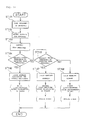
- Fig. 6 is a flow chart of the tire pressure detecting system (See Fig. 5 as for reference numerals). In the figure, the reference sign and numeral STxxx represents step Numbers.
- ST303 Whether or not fluctuations Pv per time unit exceed a first threshold fluctuation Pv1 as a threshold fluctuation (Pv>Pv1) is determined. If YES, the procedure goes to ST305, and if NO, the procedure goes to ST304.
- Warning signals are transmitted every five seconds from the fluctuation warning unit 73.
- the first light emitting diode 84 emits red light and the buzzer 91 rings.
- ST308 Whether or not the tire pressure Pk is fallen to a value below the first threshold detected value Pk1 as a threshold detected value (Pk ⁇ Pkl) is determined. If YES, the procedure goes to ST310, and if NO, the procedure goes to ST309.
- Warning signals are transmitted every 5 seconds from the detected value warning unit 78. As a consequence, the first light-emitting diode 84 emits red light.
- the fluctuation warning unit 73 is a unit for detecting fluctuations Pv of the tire pressure per unit time and transmitting a warning, which is especially effective for finding a unpredictable air leakage.
- the detected value warning unit 78 is a unit for detecting the tire pressure Pk and transmitting a warning, and is especially effective for finding air leakage that cannot be detected during gentle variation of tire pressure per unit time.
- the unpredictable air leakage that is high in degree of urgency may be rapidly detected by taking priority to processing by the fluctuation warning unit 73 that can find the unpredictable air leakage over processing by the detected value warning unit 78.
- the fluctuation warning unit 73 sets two curves representing threshold fluctuations in order to detect fluctuations Pv of the tire pressure per unit time.
- the curve representing the first threshold fluctuation Pv1 which is gentle in inclination, and the curve representing the second threshold fluctuation Pv2, which is steeper than the curve representing the first threshold fluctuation Pv1 are set.
- the graph shows that caution signals are issued when fluctuations Pv per unit time exceed the curve representing the first threshold fluctuation Pv1, and warning signals are issued when fluctuations Pv per unit time exceed the curve representing the second threshold fluctuation Pv2.
- the detected value warning unit 78 sets two curves representing thresholds of detected value in order to detect the tire pressure Pk.
- the first threshold detected value Pk1 and the second threshold detected value Pk2, which is lower in the air pressure than the first threshold detected value Pk1 are set.
- the graph shows that caution signals are issued when the tire pressure Pk is fallen to a value below the first threshold detected value Pk1, and warning signals are issued when it is fallen to the value below the second threshold detected value Pk2.
- the vehicle in the first embodiment is described as the motorcycle 10 in the first embodiment, it is not limited to a two-wheeler. Alternatively, the vehicle may be a four-wheeler or a three-wheeler.
- the receiver 81 is provided on the meter panel 37 in the first embodiment, it is not limited thereto. For example, if it is a type that issues a warning, it may be provided on the vehicle body frame or a helmet, and if it is a type using vibrations, it may be provided on a seat or on the helmet.
- the receiver 81 is described as a unit to be mounted on the front wheel 14 (See Fig. 1), it may be a unit for receiving information from the rear wheel 18.
- the fluctuation warning unit 73 and the detected value warning unit 78 are provided on the side of the transmitter 53 in the first embodiment.
- a communicator for issuing information on the tire pressure is provided on the side of the transmitter side, and the receiver for receiving information on the tire pressure from the communicator, and the receiver processes fluctuation warning and fluctuation warning.
- a tire pressure detecting system 150 according to the second embodiment will be described below.
- the same parts as those used in the tire pressure detecting system 150 in the first embodiment are represented by the same reference numerals and they are not described in detail again.
- the tire pressure detecting system 150 is constructed in such a manner that an opening 48 is formed on the wheel rim 46, a grommet 51 formed of rubber is fitted into the opening 48, a cored bar 52 is inserted into the grommet 51, and a transmitter 153 for detecting the air pressure of the tire 42 and transmitting pressure information to the outside is held by the grommet 51, and is provided with a receiver 81 for issuing a warning based on pressure information from the transmitter 153.
- the transmitter 153 includes an air pressure sensor 155 disposed in the tire 42 for detecting the air pressure in the tire, a temperature sensor 64 for detecting the air temperature in the tire 42, a pressure converting unit 66 for converting the tire pressure detected by the air pressure sensor 64 into a pressure at a predetermined temperature based on the air temperature detected by the temperature sensor 155, an air pressure determination unit 67 for determining whether a warning is necessary, caution is necessary or it is normal, based on the air pressure converted into the pressure under a reference atmospheric pressure by the pressure converting unit 66, a transmission circuit 68 for transmitting warning signals, caution signals, or signals indicating that the air pressure is normal as pressure information based on the result determined by the air pressure determination unit 67, and a transmission interval varying unit 69 for varying the transmission interval of the transmission circuit 68 by the warning signals, the caution signals, and the signals indicating that the air pressure is normal.
- the cored bar 52 is provided with a function as an antenna for transmitting pressure information from the transmission circuit 68 to the receiver 81 in addition to a function to hold the transmitter 153.
- the receiver 81 is a unit provided on a meter panel 37 (See Fig. 4) as will be described later.
- reference numeral 61 designates a battery for driving the transmitter 153
- reference numeral 62 designates a case for storing a battery 61, the temperature sensor 64, the pressure converting unit 66, the air pressure determination unit 67, the transmission circuit 68, and the transmission interval varying unit 69 together.
- the tire pressure detecting system 150 wherein the tire pressure is detected by the air pressure sensor 155 disposed on the side of the front wheel 14 (wheel) shown in Fig. 1, detected information on the tire pressure is transmitted from the transmitter 153 disposed on the side of the front wheel 14 (wheel) to the receiver 81 disposed on the side of the vehicle body frame 11 (vehicle body) shown in Fig. 1, and a warning is issued when the received tire pressure is outside the predetermined value, characterized in that the transmitter 153 is provided with a temperature sensor 64 for detecting the air temperature in the tire 42 (See Fig.
- the pressure converting unit 66 for converting the tire pressure detected by the air pressure sensor 155 into a pressure at the predetermined temperature based on the air temperature detected by the temperature sensor, and a transmission interval varying unit 69 for shortening the interval of transmission to the receiver 81 when the converted pressure supplied from the pressure converting unit 66 is fallen to a value below the predetermined threshold pressure.
- the temperature sensor 64 for detecting the air temperature in the tire 42 (See Fig. 8), and the pressure converting unit 66 for converting the tire pressure detected by the air pressure sensor 155 into a pressure at the predetermined temperature based on the air temperature detected by the temperature sensor 64 are provided in the transmitter 153 so that a temperature correction is made to the air pressure of the tire 42 to be detected.
- the temperature sensor 64 for detecting the air temperature in the tire 42 See Fig. 8
- the pressure converting unit 66 for converting the tire pressure detected by the air pressure sensor 155 into a pressure at the predetermined temperature based on the air temperature detected by the temperature sensor 64 are provided in the transmitter 153 so that a temperature correction is made to the air pressure of the tire 42 to be detected.
- the transmitter 153 since the transmitter 153 includes the transmission interval varying unit 69 for shortening the interval of transmission to the receiver 81 when the converted pressure from the pressure converting unit 66 is fallen to a value below the predetermined threshold pressure, abrupt air leakage or the like may be notified. As a consequence, convenience of tire pressure management for the driver may be improved.
- Fig. 10 is a flow chart of the tire pressure detecting system (See Fig. 9 as for reference numerals).
- the reference sign and numeral STxxx represents step numbers.
- ST203 the detected tire pressure is converted (temperature correction) into the tire pressure at the predetermined temperature.
- the predetermined temperature is assumed to be 20°C.
- the tire pressure P increases when the air temperature T in the tire increases, and decreases when the temperature T in the tire decreases.
- the tire pressure is converted at the predetermined temperature of 20 °C.
- ST204 Whether or not the tire pressure Pk exceeds a first threshold detected pressure Pk1 is determined, where Pk represents the converted tire pressures, and Pk1 represents the first threshold detected value as a predetermined threshold pressure (Pk>pk1). If YES, the procedure goes to ST206, and if NO, the procedure goes to ST205.
- Step205 Whether or not the tire pressure Pk exceeds the second threshold detected tire pressure Pk2 is determined, where Pk2 is the second threshold detected tire pressure Pk2 as a value predetermined under certain conditions (Pk>Pk2). If YES, the procedure goes to ST207, and if NO, the procedure goes to ST 208.
- Warning signals are issued every 5 seconds. As a consequence, the first light emitting diode 84 emits red light and the buzzer 91 rings.
- reference sign Pk represents the tire pressure after the temperature is corrected (converted), and Pa represents the tire pressure before the temperature is not corrected.
- the transmitter 153 is provided with the temperature sensor 64 for detecting the air temperature in the tire 42 (See Fig. 8), and the pressure converting unit 66 for converting the tire pressure detected by the air pressure sensor 155 into a pressure at the predetermined temperature based on the air temperature detected by the temperature sensor 64 to make a temperature correction to the air pressure of the tire 42 to be detected.
- the temperature sensor 64 for detecting the air temperature in the tire 42
- the pressure converting unit 66 for converting the tire pressure detected by the air pressure sensor 155 into a pressure at the predetermined temperature based on the air temperature detected by the temperature sensor 64 to make a temperature correction to the air pressure of the tire 42 to be detected.
- the vehicle in the second embodiment is described as the motorcycle 10, it is not limited to a two-wheeler.
- the vehicle may be a four-wheeler or a three-wheeler.
- the receiver 81 is provided on the meter panel 37 in the second embodiment, it is not limited thereto. For example, if it is a type that issues a warning, it may be provided on the vehicle body frame or a helmet, and if it is a type using vibrations, it may be provided on a seat or on the helmet.
- the receiver 81 is described as a unit to be mounted on the front wheel 14 (See Fig. 1), it may be a unit for receiving information from the rear wheel 18.
- the pressure converting unit 66 is provided on the side of the transmitter 153.
- it is not limited thereto, and, for example, it may be adapted in such a manner that information on the air pressure and information on air temperature in the tire are issued to the receiver, so that it is processed in the receiver.
- a tire pressure detecting system 250 according to the third embodiment will be described below.
- the same parts as those used in the tire pressure detecting system 250 in the first embodiment are represented by the same reference numerals and they are not described in detail again.
- the tire pressure detecting system 250 is constructed in such a manner that an opening 48 is formed on the wheel rim 46, a grommet 51 formed of rubber is fitted into the opening 48, a cored bar 52 is inserted into the grommet 51, and a transmitter 253 for detecting the air pressure of the tire 42 and transmitting pressure information to the outside is held by the grommet 51, and is provided with a receiver 81 for issuing a warning based on pressure information supplied from the transmitter 253.
- the transmitter 253 includes an outside air pressure sensor 54 embedded in the grommet51 on the inner side with respect to the wheel rim 46, an air pressure sensor 255 disposed in the tire 42 for detecting the air pressure of the tire 42, a pressure converting unit 56 for converting the tire pressure detected by the air pressure sensor 255 into a pressure under the reference atmospheric pressure based on the outside pressure detected by the outside air pressure sensor 54, an air pressure determination unit 57 for determining whether a warning is necessary, caution is necessary, or it is normal based on the air pressure converted into the pressure under the reference atmospheric pressure by the pressure converting unit 56, and a transmission circuit 58 for transmitting warning signals, caution signals or signals indicating that the air pressure is normal as pressure information based on the result determined by the air pressure determination unit 57.
- the cored bar 52 is provided with a function as an antenna for transmitting pressure information from the transmission circuit 58 to the receiver 81 as well as a function to hold the transmitter 53.
- the receiver 81 is a unit provided with a meter panel 37 (See Fig. 4) as will be described later.
- reference numeral 61 designates a battery for driving the transmitter 253
- reference numeral 62 designates a case for storing the pressure converting unit 56, the air pressure determination unit 57, the transmission circuit 58, and a battery 61 altogether.
- the tire pressure detecting system 250 wherein the tire pressure is detected by the air pressure sensor 255, and a warning is issued when the tire pressure lies outside the predetermined value, comprising the outside air pressure sensor 54 for detecting outside air pressures, and a pressure converting unit 56 for converting a tire pressure detected by the air pressure sensor 255 into a pressure under the reference atmospheric pressure based on the outside air pressure detected by the outside air pressure sensor 54.
- the tire pressure detecting system 50 is constructed in such a manner that the outside air pressure is detected by the outside air pressure sensor 54, and the tire pressure detected by the air pressure sensor 255 is converted into a pressure under the reference atmospheric pressure by the pressure converting unit 56 based on the outside air pressure.
- a converted pressure of 180 kPa may be obtained regardless of the height from the ground in the example described above.
- the system is adapted to issue a warning when the tire pressure lies outside the value predetermined under certain conditions.
- convenience of the tire pressure management for the driver may be improved.
- Fig. 14 is a flow chart of the tire pressure detecting system according to the present invention (See Fig. 13 as for reference numerals).
- the reference sign and numeral STxxx represents step Nos.
- ST102 the outside air pressure is detected by the outside air pressure 54.
- ST103 the detected tire pressure is converted into the tire pressure obtained under the condition that the outside air pressure is 1 atm, which is the reference atmospheric pressure.
- ST104 Whether or not the tire pressure Pk exceeds a first threshold of detected tire pressurePk1 is determined, where Pk is the converted tire pressure (corresponds to p 13 described above) and Pk1 is the first threshold of detected tire pressure Pk1 as a predetermined value under certain conditions (Pk>pk1). If YES, the procedure goes to ST106, and if NO, the procedure goes to ST105.
- reference sign Pk represents the tire pressure after the pressure is corrected (converted)
- reference sign Pa represents the tire pressure when the vehicle is moved to high altitudes after the tire pressure is adjusted at the level ground (1 atm).
- the tire pressure drifts in the area defined by two curves of the tire pressure Pk and the tire pressure Pa when the motorcycle 10 (See Fig. 1) is moved from the level ground to high altitudes. Therefore, the first threshold of detected tire pressure Pk1 for issuing the predetermined caution signals and the second threshold of detected tire pressure Pk2 for issuing the warning signals vary as well, which is not preferable.
- the system is adapted to detect the outside air pressure by the outside air pressure sensor 54 and to convert the tire pressure detected by the air pressure sensor 255 into a pressure under the reference atmospheric pressure by the pressure converting unit 56 based on the outside air pressure. Accordingly, the system may issue a warning when the tire pressure lies outside the value predetermined under certain conditions regardless of whether it is at high altitudes or at the level ground. As a consequence, convenience of the tire pressure management for the driver may be improved.
- the vehicle in the third embodiment is described as the motorcycle 10, it is not limited to two-wheelers. Alternatively, the vehicle may be a four-wheeler or a three-wheeler.
- the receiver 81 is provided on the meter panel 37 in the third embodiment, it is not limited thereto. For example, if it is a type that issues an alarm, it may be provided on a vehicle body frame or a helmet, and if it is a type using vibrations, it may be provided on a seat or on the helmet.
- the receiver 81 is described as a unit to be mounted on the front wheel 14 (See Fig. 1), it may be a unit for receiving information from the rear wheel 18.
- the outside air pressure sensor 54 is provided in the grommet 51 of the front wheel 14.
- a sensor for detecting the outside air pressure of a fuel injection system may be utilized.
- the pressure converting unit may be provided on the receiver.
- the system of the invention may be applied to various types of vehicles including two-wheelers, three-wheelers, and four-wheelers.
- a fluctuation warning unit 73 for issuing a warning when fluctuations of the tire pressure per unit time exceed a predetermined threshold fluctuation, and a detected value warning unit 78 for issuing a warning when a detected value of the tire pressure is fallen to a value below a predetermined threshold detected value are provided.
- air leakage may be recognized rapidly, and abnormalities of air pressure may be recognized even when such faint air leakage that fluctuations of the tire pressure per unit time do not exceed the predetermined threshold fluctuation.
Applications Claiming Priority (10)
| Application Number | Priority Date | Filing Date | Title |
|---|---|---|---|
| JP2001382808 | 2001-12-17 | ||
| JP2001382799 | 2001-12-17 | ||
| JP2001382793A JP4153200B2 (ja) | 2001-12-17 | 2001-12-17 | タイヤ空気圧検知装置 |
| JP2001382799 | 2001-12-17 | ||
| JP2001382808 | 2001-12-17 | ||
| JP2001382793 | 2001-12-17 | ||
| JP2002206884 | 2002-07-16 | ||
| JP2002206937A JP3943454B2 (ja) | 2001-12-17 | 2002-07-16 | タイヤ空気圧検知装置 |
| JP2002206937 | 2002-07-16 | ||
| JP2002206884A JP3938522B2 (ja) | 2001-12-17 | 2002-07-16 | タイヤ空気圧検知装置 |
Publications (3)
| Publication Number | Publication Date |
|---|---|
| EP1319530A2 true EP1319530A2 (de) | 2003-06-18 |
| EP1319530A3 EP1319530A3 (de) | 2003-09-24 |
| EP1319530B1 EP1319530B1 (de) | 2008-03-19 |
Family
ID=27532058
Family Applications (1)
| Application Number | Title | Priority Date | Filing Date |
|---|---|---|---|
| EP02027929A Expired - Fee Related EP1319530B1 (de) | 2001-12-17 | 2002-12-13 | Vorrichtung zur Reifendruckerkennung |
Country Status (3)
| Country | Link |
|---|---|
| US (1) | US7075417B2 (de) |
| EP (1) | EP1319530B1 (de) |
| DE (1) | DE60225658T2 (de) |
Cited By (4)
| Publication number | Priority date | Publication date | Assignee | Title |
|---|---|---|---|---|
| GB2416400A (en) * | 2004-07-19 | 2006-01-25 | Ford Global Tech Llc | Detecting leakage from a tyre |
| WO2006027044A1 (en) * | 2004-09-09 | 2006-03-16 | Pirelli Tyre S.P.A. | Wheel assembly with internal pressure reservoir and pressure fluctuation warning system |
| DE102005043899B4 (de) * | 2004-09-14 | 2009-04-09 | Lear Corp., Southfield | Abgedichtete Montage einer Reifenüberwachungsbaugruppe |
| WO2015144353A1 (de) * | 2014-03-27 | 2015-10-01 | Wagatha Walter | Rad mit einem fluidbefüllten reifen und einer vorrichtung zum einstellen des reifendrucks sowie mit solchen rädern ausgerüstetes fahrrad, kraftfahrzeug oder luftfahrzeug |
Families Citing this family (12)
| Publication number | Priority date | Publication date | Assignee | Title |
|---|---|---|---|---|
| US7744553B2 (en) | 2003-12-16 | 2010-06-29 | Baxter International Inc. | Medical fluid therapy flow control systems and methods |
| JP4066947B2 (ja) * | 2003-12-19 | 2008-03-26 | 株式会社デンソー | タイヤ空気圧検出装置 |
| JP4604755B2 (ja) * | 2005-02-15 | 2011-01-05 | 横浜ゴム株式会社 | タイヤ情報送信装置およびこれを用いたタイヤ情報取得システム |
| BRPI0620675A2 (pt) * | 2005-12-15 | 2011-11-22 | Goodyear Tire & Rubber | método de determinar propriedades de veìculos |
| US7667583B2 (en) | 2006-02-13 | 2010-02-23 | Measurement Ltd. | Tire pressure gauge |
| FR2900099B1 (fr) * | 2006-04-21 | 2008-07-04 | Michelin Soc Tech | Methode de confirmation d'une alerte de pression dans un systeme de surveillance de pession |
| JP5271056B2 (ja) * | 2008-11-28 | 2013-08-21 | 本田技研工業株式会社 | タイヤ空気圧検出装置 |
| JP5041005B2 (ja) | 2009-04-24 | 2012-10-03 | トヨタ自動車株式会社 | タイヤ空気圧監視装置 |
| JP5246077B2 (ja) * | 2009-07-09 | 2013-07-24 | 日産自動車株式会社 | タイヤ空気圧検出装置、タイヤ空気圧監視システムおよびタイヤ空気圧送信方法 |
| DE102010052916B4 (de) | 2010-11-30 | 2016-09-15 | Carbofibretec Gmbh | Laufrad eines Fahrrades mit Dehnungsmessstreifen und/oder LED-Anzeige sowie Fahrrad |
| FR2989315B1 (fr) * | 2012-04-12 | 2014-05-02 | Continental Automotive France | Procede de detection de fuite d'un pneumatique de vehicule |
| CN105291721B (zh) * | 2015-11-27 | 2017-06-23 | 惠州华阳通用电子有限公司 | 一种tpms胎压误报警判别方法与装置 |
Citations (10)
| Publication number | Priority date | Publication date | Assignee | Title |
|---|---|---|---|---|
| US4186377A (en) * | 1976-03-11 | 1980-01-29 | Safety Research & Engineering Corporation | Method and apparatus for monitoring tire pressure |
| US4909074A (en) * | 1985-11-07 | 1990-03-20 | Uniroyal Englebert Reifen Gmbh | Method of determining a variable air pressure value of a pneumatic vehicle tire and indicating a pressure value |
| US5473938A (en) * | 1993-08-03 | 1995-12-12 | Mclaughlin Electronics | Method and system for monitoring a parameter of a vehicle tire |
| US5895846A (en) * | 1996-01-26 | 1999-04-20 | Compagnie Generale Des Etablissements Michelin-Michelin & Cie | Method of processing signals in a system for monitoring the tires of a vehicle during travel |
| US5965808A (en) * | 1995-12-12 | 1999-10-12 | Normann; Norbert | Method of operating tire pressure signalling devices on wheels fitted with pneumatic tires |
| WO1999061265A1 (en) * | 1998-05-22 | 1999-12-02 | Automotive Technologies Limited | A remote tyre pressure monitoring system |
| EP0989001A2 (de) * | 1998-09-21 | 2000-03-29 | Toyota Jidosha Kabushiki Kaisha | Reifendrucküberwacher |
| EP1024034A2 (de) * | 1999-01-29 | 2000-08-02 | Eaton Corporation | Gehäuse für Drucksensor |
| EP1092570A1 (de) * | 1999-10-12 | 2001-04-18 | Pacific Industrial Co., Ltd. | Gerät und Verfahren zur Signalübertragung in einer Einrichtung zum Überwachen des Luftdruckes in den Luftreifen eines Fahrzeuges |
| EP1216854A2 (de) * | 2000-12-19 | 2002-06-26 | Pacific Industrial Co., Ltd. | Gerät und Verfahren zur Signalübertragung in einer Einrichtung zum Überwachen des Reifenzustands eines Fahrzeuges |
Family Cites Families (3)
| Publication number | Priority date | Publication date | Assignee | Title |
|---|---|---|---|---|
| JPS6444726A (en) | 1987-08-11 | 1989-02-17 | Kenjiyuurou Yagi | Preparation of three-dimensional plastic pipe |
| US5231872A (en) * | 1991-02-21 | 1993-08-03 | Ttc/Truck Tech Corp. | Tire monitoring apparatus and method |
| DE10144361B4 (de) * | 2001-09-10 | 2005-09-29 | Siemens Ag | Verfahren und System zum Detektieren eines Druckabfalls in einem Reifen |
-
2002
- 2002-12-13 DE DE60225658T patent/DE60225658T2/de not_active Expired - Lifetime
- 2002-12-13 EP EP02027929A patent/EP1319530B1/de not_active Expired - Fee Related
- 2002-12-16 US US10/319,607 patent/US7075417B2/en not_active Expired - Fee Related
Patent Citations (10)
| Publication number | Priority date | Publication date | Assignee | Title |
|---|---|---|---|---|
| US4186377A (en) * | 1976-03-11 | 1980-01-29 | Safety Research & Engineering Corporation | Method and apparatus for monitoring tire pressure |
| US4909074A (en) * | 1985-11-07 | 1990-03-20 | Uniroyal Englebert Reifen Gmbh | Method of determining a variable air pressure value of a pneumatic vehicle tire and indicating a pressure value |
| US5473938A (en) * | 1993-08-03 | 1995-12-12 | Mclaughlin Electronics | Method and system for monitoring a parameter of a vehicle tire |
| US5965808A (en) * | 1995-12-12 | 1999-10-12 | Normann; Norbert | Method of operating tire pressure signalling devices on wheels fitted with pneumatic tires |
| US5895846A (en) * | 1996-01-26 | 1999-04-20 | Compagnie Generale Des Etablissements Michelin-Michelin & Cie | Method of processing signals in a system for monitoring the tires of a vehicle during travel |
| WO1999061265A1 (en) * | 1998-05-22 | 1999-12-02 | Automotive Technologies Limited | A remote tyre pressure monitoring system |
| EP0989001A2 (de) * | 1998-09-21 | 2000-03-29 | Toyota Jidosha Kabushiki Kaisha | Reifendrucküberwacher |
| EP1024034A2 (de) * | 1999-01-29 | 2000-08-02 | Eaton Corporation | Gehäuse für Drucksensor |
| EP1092570A1 (de) * | 1999-10-12 | 2001-04-18 | Pacific Industrial Co., Ltd. | Gerät und Verfahren zur Signalübertragung in einer Einrichtung zum Überwachen des Luftdruckes in den Luftreifen eines Fahrzeuges |
| EP1216854A2 (de) * | 2000-12-19 | 2002-06-26 | Pacific Industrial Co., Ltd. | Gerät und Verfahren zur Signalübertragung in einer Einrichtung zum Überwachen des Reifenzustands eines Fahrzeuges |
Cited By (5)
| Publication number | Priority date | Publication date | Assignee | Title |
|---|---|---|---|---|
| GB2416400A (en) * | 2004-07-19 | 2006-01-25 | Ford Global Tech Llc | Detecting leakage from a tyre |
| WO2006027044A1 (en) * | 2004-09-09 | 2006-03-16 | Pirelli Tyre S.P.A. | Wheel assembly with internal pressure reservoir and pressure fluctuation warning system |
| US7444859B2 (en) | 2004-09-09 | 2008-11-04 | Pirelli Tyre S.P.A. | Wheel assembly with internal pressure reservoir and pressure fluctuation warning system |
| DE102005043899B4 (de) * | 2004-09-14 | 2009-04-09 | Lear Corp., Southfield | Abgedichtete Montage einer Reifenüberwachungsbaugruppe |
| WO2015144353A1 (de) * | 2014-03-27 | 2015-10-01 | Wagatha Walter | Rad mit einem fluidbefüllten reifen und einer vorrichtung zum einstellen des reifendrucks sowie mit solchen rädern ausgerüstetes fahrrad, kraftfahrzeug oder luftfahrzeug |
Also Published As
| Publication number | Publication date |
|---|---|
| DE60225658T2 (de) | 2009-04-16 |
| US7075417B2 (en) | 2006-07-11 |
| EP1319530B1 (de) | 2008-03-19 |
| US20040233049A1 (en) | 2004-11-25 |
| EP1319530A3 (de) | 2003-09-24 |
| DE60225658D1 (de) | 2008-04-30 |
Similar Documents
| Publication | Publication Date | Title |
|---|---|---|
| EP1319530A2 (de) | Vorrichtung zur Reifendruckerkennung | |
| US7236892B2 (en) | Vehicle wheel state monitoring device and method | |
| US5602524A (en) | Device for monitoring the air-pressure in pneumatic tires fitted on vehicle wheels | |
| AU680428B2 (en) | Tyre condition monitoring | |
| US20100164705A1 (en) | Self-powered sensor system for monitoring tire pressure | |
| US20020113692A1 (en) | System for monitoring and for signaling by radio the pressure in pneumatic tires on motor vehicles | |
| US8232870B2 (en) | Vehicle control apparatus and vehicle having the same | |
| WO2012139711A1 (fr) | Procede de localisation de la position de roues d'un vehicule | |
| FR2835474A1 (fr) | Procede et systeme de surveillance de pression de gonflage de pneumatique | |
| WO2003000509A3 (en) | Tire sensor | |
| US7791460B2 (en) | Tire pressure monitoring system with reliable wireless communication between wheel-based transceivers and vehicle body-based transceiver | |
| JP2005119370A (ja) | タイヤ状態監視装置の送信機 | |
| JP3943454B2 (ja) | タイヤ空気圧検知装置 | |
| JP2004155222A (ja) | タイヤ状態監視装置 | |
| CA2413987C (en) | Tire pressure fluctuation detecting system | |
| US6765482B2 (en) | Air pressure sensor fitting structure for vehicle wheel | |
| TW202321054A (zh) | 用於自行車輪的壓力感測總成 | |
| EP3049260B1 (de) | Verfahren und dessen system zur reifenüberwachung | |
| US7116217B2 (en) | Transmitter and receiver for tire condition monitoring apparatus | |
| JP2003246211A (ja) | タイヤ空気圧検知装置 | |
| EP1447244B1 (de) | Einbaustruktur des Drucküberwachungssystem eines Reifens | |
| JP2016130049A (ja) | タイヤ空気圧センサ | |
| KR200445014Y1 (ko) | 타이어 공기압 측정용 압력센서 및 이를 구비한 타이어공기압 모니터링 시스템 | |
| US20020097147A1 (en) | Air pressure detection device for wheel | |
| JP4153200B2 (ja) | タイヤ空気圧検知装置 |
Legal Events
| Date | Code | Title | Description |
|---|---|---|---|
| PUAI | Public reference made under article 153(3) epc to a published international application that has entered the european phase |
Free format text: ORIGINAL CODE: 0009012 |
|
| AK | Designated contracting states |
Designated state(s): AT BE BG CH CY CZ DE DK EE ES FI FR GB GR IE IT LI LU MC NL PT SE SI SK TR |
|
| AX | Request for extension of the european patent |
Extension state: AL LT LV MK RO |
|
| PUAL | Search report despatched |
Free format text: ORIGINAL CODE: 0009013 |
|
| AK | Designated contracting states |
Kind code of ref document: A3 Designated state(s): AT BE BG CH CY CZ DE DK EE ES FI FR GB GR IE IT LI LU MC NL PT SE SI SK TR |
|
| AX | Request for extension of the european patent |
Extension state: AL LT LV MK RO |
|
| 17P | Request for examination filed |
Effective date: 20031030 |
|
| AKX | Designation fees paid |
Designated state(s): DE GB IT |
|
| 17Q | First examination report despatched |
Effective date: 20050211 |
|
| GRAP | Despatch of communication of intention to grant a patent |
Free format text: ORIGINAL CODE: EPIDOSNIGR1 |
|
| RIN1 | Information on inventor provided before grant (corrected) |
Inventor name: YAMAGIWA, TOSHIO Inventor name: HARADA, TOMOYUKI |
|
| RAP1 | Party data changed (applicant data changed or rights of an application transferred) |
Owner name: HONDA GIKEN KOGYO KABUSHIKI KAISHA |
|
| GRAS | Grant fee paid |
Free format text: ORIGINAL CODE: EPIDOSNIGR3 |
|
| GRAA | (expected) grant |
Free format text: ORIGINAL CODE: 0009210 |
|
| AK | Designated contracting states |
Kind code of ref document: B1 Designated state(s): DE GB IT |
|
| REG | Reference to a national code |
Ref country code: GB Ref legal event code: FG4D |
|
| REF | Corresponds to: |
Ref document number: 60225658 Country of ref document: DE Date of ref document: 20080430 Kind code of ref document: P |
|
| PLBE | No opposition filed within time limit |
Free format text: ORIGINAL CODE: 0009261 |
|
| STAA | Information on the status of an ep patent application or granted ep patent |
Free format text: STATUS: NO OPPOSITION FILED WITHIN TIME LIMIT |
|
| 26N | No opposition filed |
Effective date: 20081222 |
|
| PGFP | Annual fee paid to national office [announced via postgrant information from national office to epo] |
Ref country code: DE Payment date: 20121205 Year of fee payment: 11 |
|
| PGFP | Annual fee paid to national office [announced via postgrant information from national office to epo] |
Ref country code: GB Payment date: 20121212 Year of fee payment: 11 Ref country code: IT Payment date: 20121215 Year of fee payment: 11 |
|
| REG | Reference to a national code |
Ref country code: DE Ref legal event code: R119 Ref document number: 60225658 Country of ref document: DE |
|
| GBPC | Gb: european patent ceased through non-payment of renewal fee |
Effective date: 20131213 |
|
| REG | Reference to a national code |
Ref country code: DE Ref legal event code: R119 Ref document number: 60225658 Country of ref document: DE Effective date: 20140701 |
|
| PG25 | Lapsed in a contracting state [announced via postgrant information from national office to epo] |
Ref country code: DE Free format text: LAPSE BECAUSE OF NON-PAYMENT OF DUE FEES Effective date: 20140701 |
|
| PG25 | Lapsed in a contracting state [announced via postgrant information from national office to epo] |
Ref country code: GB Free format text: LAPSE BECAUSE OF NON-PAYMENT OF DUE FEES Effective date: 20131213 |
|
| PG25 | Lapsed in a contracting state [announced via postgrant information from national office to epo] |
Ref country code: IT Free format text: LAPSE BECAUSE OF NON-PAYMENT OF DUE FEES Effective date: 20131231 |
|
| PG25 | Lapsed in a contracting state [announced via postgrant information from national office to epo] |
Ref country code: IT Free format text: LAPSE BECAUSE OF NON-PAYMENT OF DUE FEES Effective date: 20131213 |