EP1319495A1 - Film joining method, a wide film produced by the joining method and a covering material for agricultural use made of the wide film - Google Patents
Film joining method, a wide film produced by the joining method and a covering material for agricultural use made of the wide film Download PDFInfo
- Publication number
- EP1319495A1 EP1319495A1 EP02027592A EP02027592A EP1319495A1 EP 1319495 A1 EP1319495 A1 EP 1319495A1 EP 02027592 A EP02027592 A EP 02027592A EP 02027592 A EP02027592 A EP 02027592A EP 1319495 A1 EP1319495 A1 EP 1319495A1
- Authority
- EP
- European Patent Office
- Prior art keywords
- film
- films
- melt
- width
- joining method
- Prior art date
- Legal status (The legal status is an assumption and is not a legal conclusion. Google has not performed a legal analysis and makes no representation as to the accuracy of the status listed.)
- Granted
Links
Images


Classifications
-
- B—PERFORMING OPERATIONS; TRANSPORTING
- B29—WORKING OF PLASTICS; WORKING OF SUBSTANCES IN A PLASTIC STATE IN GENERAL
- B29C—SHAPING OR JOINING OF PLASTICS; SHAPING OF MATERIAL IN A PLASTIC STATE, NOT OTHERWISE PROVIDED FOR; AFTER-TREATMENT OF THE SHAPED PRODUCTS, e.g. REPAIRING
- B29C66/00—General aspects of processes or apparatus for joining preformed parts
- B29C66/40—General aspects of joining substantially flat articles, e.g. plates, sheets or web-like materials; Making flat seams in tubular or hollow articles; Joining single elements to substantially flat surfaces
- B29C66/41—Joining substantially flat articles ; Making flat seams in tubular or hollow articles
- B29C66/43—Joining a relatively small portion of the surface of said articles
-
- B—PERFORMING OPERATIONS; TRANSPORTING
- B29—WORKING OF PLASTICS; WORKING OF SUBSTANCES IN A PLASTIC STATE IN GENERAL
- B29C—SHAPING OR JOINING OF PLASTICS; SHAPING OF MATERIAL IN A PLASTIC STATE, NOT OTHERWISE PROVIDED FOR; AFTER-TREATMENT OF THE SHAPED PRODUCTS, e.g. REPAIRING
- B29C65/00—Joining or sealing of preformed parts, e.g. welding of plastics materials; Apparatus therefor
- B29C65/02—Joining or sealing of preformed parts, e.g. welding of plastics materials; Apparatus therefor by heating, with or without pressure
-
- A—HUMAN NECESSITIES
- A01—AGRICULTURE; FORESTRY; ANIMAL HUSBANDRY; HUNTING; TRAPPING; FISHING
- A01G—HORTICULTURE; CULTIVATION OF VEGETABLES, FLOWERS, RICE, FRUIT, VINES, HOPS OR SEAWEED; FORESTRY; WATERING
- A01G9/00—Cultivation in receptacles, forcing-frames or greenhouses; Edging for beds, lawn or the like
- A01G9/14—Greenhouses
- A01G9/1438—Covering materials therefor; Materials for protective coverings used for soil and plants, e.g. films, canopies, tunnels or cloches
-
- B—PERFORMING OPERATIONS; TRANSPORTING
- B29—WORKING OF PLASTICS; WORKING OF SUBSTANCES IN A PLASTIC STATE IN GENERAL
- B29C—SHAPING OR JOINING OF PLASTICS; SHAPING OF MATERIAL IN A PLASTIC STATE, NOT OTHERWISE PROVIDED FOR; AFTER-TREATMENT OF THE SHAPED PRODUCTS, e.g. REPAIRING
- B29C65/00—Joining or sealing of preformed parts, e.g. welding of plastics materials; Apparatus therefor
- B29C65/48—Joining or sealing of preformed parts, e.g. welding of plastics materials; Apparatus therefor using adhesives, i.e. using supplementary joining material; solvent bonding
- B29C65/4805—Joining or sealing of preformed parts, e.g. welding of plastics materials; Apparatus therefor using adhesives, i.e. using supplementary joining material; solvent bonding characterised by the type of adhesives
- B29C65/481—Non-reactive adhesives, e.g. physically hardening adhesives
- B29C65/4815—Hot melt adhesives, e.g. thermoplastic adhesives
-
- B—PERFORMING OPERATIONS; TRANSPORTING
- B29—WORKING OF PLASTICS; WORKING OF SUBSTANCES IN A PLASTIC STATE IN GENERAL
- B29C—SHAPING OR JOINING OF PLASTICS; SHAPING OF MATERIAL IN A PLASTIC STATE, NOT OTHERWISE PROVIDED FOR; AFTER-TREATMENT OF THE SHAPED PRODUCTS, e.g. REPAIRING
- B29C65/00—Joining or sealing of preformed parts, e.g. welding of plastics materials; Apparatus therefor
- B29C65/48—Joining or sealing of preformed parts, e.g. welding of plastics materials; Apparatus therefor using adhesives, i.e. using supplementary joining material; solvent bonding
- B29C65/50—Joining or sealing of preformed parts, e.g. welding of plastics materials; Apparatus therefor using adhesives, i.e. using supplementary joining material; solvent bonding using adhesive tape, e.g. thermoplastic tape; using threads or the like
- B29C65/5042—Joining or sealing of preformed parts, e.g. welding of plastics materials; Apparatus therefor using adhesives, i.e. using supplementary joining material; solvent bonding using adhesive tape, e.g. thermoplastic tape; using threads or the like covering both elements to be joined
-
- B—PERFORMING OPERATIONS; TRANSPORTING
- B29—WORKING OF PLASTICS; WORKING OF SUBSTANCES IN A PLASTIC STATE IN GENERAL
- B29C—SHAPING OR JOINING OF PLASTICS; SHAPING OF MATERIAL IN A PLASTIC STATE, NOT OTHERWISE PROVIDED FOR; AFTER-TREATMENT OF THE SHAPED PRODUCTS, e.g. REPAIRING
- B29C66/00—General aspects of processes or apparatus for joining preformed parts
- B29C66/01—General aspects dealing with the joint area or with the area to be joined
- B29C66/02—Preparation of the material, in the area to be joined, prior to joining or welding
-
- B—PERFORMING OPERATIONS; TRANSPORTING
- B29—WORKING OF PLASTICS; WORKING OF SUBSTANCES IN A PLASTIC STATE IN GENERAL
- B29C—SHAPING OR JOINING OF PLASTICS; SHAPING OF MATERIAL IN A PLASTIC STATE, NOT OTHERWISE PROVIDED FOR; AFTER-TREATMENT OF THE SHAPED PRODUCTS, e.g. REPAIRING
- B29C66/00—General aspects of processes or apparatus for joining preformed parts
- B29C66/01—General aspects dealing with the joint area or with the area to be joined
- B29C66/03—After-treatments in the joint area
- B29C66/034—Thermal after-treatments
- B29C66/0342—Cooling, e.g. transporting through welding and cooling zone
-
- B—PERFORMING OPERATIONS; TRANSPORTING
- B29—WORKING OF PLASTICS; WORKING OF SUBSTANCES IN A PLASTIC STATE IN GENERAL
- B29C—SHAPING OR JOINING OF PLASTICS; SHAPING OF MATERIAL IN A PLASTIC STATE, NOT OTHERWISE PROVIDED FOR; AFTER-TREATMENT OF THE SHAPED PRODUCTS, e.g. REPAIRING
- B29C66/00—General aspects of processes or apparatus for joining preformed parts
- B29C66/01—General aspects dealing with the joint area or with the area to be joined
- B29C66/05—Particular design of joint configurations
- B29C66/10—Particular design of joint configurations particular design of the joint cross-sections
- B29C66/11—Joint cross-sections comprising a single joint-segment, i.e. one of the parts to be joined comprising a single joint-segment in the joint cross-section
- B29C66/114—Single butt joints
- B29C66/1142—Single butt to butt joints
-
- B—PERFORMING OPERATIONS; TRANSPORTING
- B29—WORKING OF PLASTICS; WORKING OF SUBSTANCES IN A PLASTIC STATE IN GENERAL
- B29C—SHAPING OR JOINING OF PLASTICS; SHAPING OF MATERIAL IN A PLASTIC STATE, NOT OTHERWISE PROVIDED FOR; AFTER-TREATMENT OF THE SHAPED PRODUCTS, e.g. REPAIRING
- B29C66/00—General aspects of processes or apparatus for joining preformed parts
- B29C66/01—General aspects dealing with the joint area or with the area to be joined
- B29C66/345—Progressively making the joint, e.g. starting from the middle
- B29C66/3452—Making complete joints by combining partial joints
-
- B—PERFORMING OPERATIONS; TRANSPORTING
- B29—WORKING OF PLASTICS; WORKING OF SUBSTANCES IN A PLASTIC STATE IN GENERAL
- B29C—SHAPING OR JOINING OF PLASTICS; SHAPING OF MATERIAL IN A PLASTIC STATE, NOT OTHERWISE PROVIDED FOR; AFTER-TREATMENT OF THE SHAPED PRODUCTS, e.g. REPAIRING
- B29C66/00—General aspects of processes or apparatus for joining preformed parts
- B29C66/01—General aspects dealing with the joint area or with the area to be joined
- B29C66/347—General aspects dealing with the joint area or with the area to be joined using particular temperature distributions or gradients; using particular heat distributions or gradients
- B29C66/3472—General aspects dealing with the joint area or with the area to be joined using particular temperature distributions or gradients; using particular heat distributions or gradients in the plane of the joint, e.g. along the joint line in the plane of the joint or perpendicular to the joint line in the plane of the joint
-
- B—PERFORMING OPERATIONS; TRANSPORTING
- B29—WORKING OF PLASTICS; WORKING OF SUBSTANCES IN A PLASTIC STATE IN GENERAL
- B29C—SHAPING OR JOINING OF PLASTICS; SHAPING OF MATERIAL IN A PLASTIC STATE, NOT OTHERWISE PROVIDED FOR; AFTER-TREATMENT OF THE SHAPED PRODUCTS, e.g. REPAIRING
- B29C66/00—General aspects of processes or apparatus for joining preformed parts
- B29C66/70—General aspects of processes or apparatus for joining preformed parts characterised by the composition, physical properties or the structure of the material of the parts to be joined; Joining with non-plastics material
- B29C66/72—General aspects of processes or apparatus for joining preformed parts characterised by the composition, physical properties or the structure of the material of the parts to be joined; Joining with non-plastics material characterised by the structure of the material of the parts to be joined
- B29C66/723—General aspects of processes or apparatus for joining preformed parts characterised by the composition, physical properties or the structure of the material of the parts to be joined; Joining with non-plastics material characterised by the structure of the material of the parts to be joined being multi-layered
-
- B—PERFORMING OPERATIONS; TRANSPORTING
- B29—WORKING OF PLASTICS; WORKING OF SUBSTANCES IN A PLASTIC STATE IN GENERAL
- B29C—SHAPING OR JOINING OF PLASTICS; SHAPING OF MATERIAL IN A PLASTIC STATE, NOT OTHERWISE PROVIDED FOR; AFTER-TREATMENT OF THE SHAPED PRODUCTS, e.g. REPAIRING
- B29C66/00—General aspects of processes or apparatus for joining preformed parts
- B29C66/70—General aspects of processes or apparatus for joining preformed parts characterised by the composition, physical properties or the structure of the material of the parts to be joined; Joining with non-plastics material
- B29C66/73—General aspects of processes or apparatus for joining preformed parts characterised by the composition, physical properties or the structure of the material of the parts to be joined; Joining with non-plastics material characterised by the intensive physical properties of the material of the parts to be joined, by the optical properties of the material of the parts to be joined, by the extensive physical properties of the parts to be joined, by the state of the material of the parts to be joined or by the material of the parts to be joined being a thermoplastic or a thermoset
- B29C66/731—General aspects of processes or apparatus for joining preformed parts characterised by the composition, physical properties or the structure of the material of the parts to be joined; Joining with non-plastics material characterised by the intensive physical properties of the material of the parts to be joined, by the optical properties of the material of the parts to be joined, by the extensive physical properties of the parts to be joined, by the state of the material of the parts to be joined or by the material of the parts to be joined being a thermoplastic or a thermoset characterised by the intensive physical properties of the material of the parts to be joined
- B29C66/7317—Hydrophilicity or hydrophobicity
- B29C66/73171—Hydrophilicity
-
- B—PERFORMING OPERATIONS; TRANSPORTING
- B29—WORKING OF PLASTICS; WORKING OF SUBSTANCES IN A PLASTIC STATE IN GENERAL
- B29C—SHAPING OR JOINING OF PLASTICS; SHAPING OF MATERIAL IN A PLASTIC STATE, NOT OTHERWISE PROVIDED FOR; AFTER-TREATMENT OF THE SHAPED PRODUCTS, e.g. REPAIRING
- B29C66/00—General aspects of processes or apparatus for joining preformed parts
- B29C66/70—General aspects of processes or apparatus for joining preformed parts characterised by the composition, physical properties or the structure of the material of the parts to be joined; Joining with non-plastics material
- B29C66/73—General aspects of processes or apparatus for joining preformed parts characterised by the composition, physical properties or the structure of the material of the parts to be joined; Joining with non-plastics material characterised by the intensive physical properties of the material of the parts to be joined, by the optical properties of the material of the parts to be joined, by the extensive physical properties of the parts to be joined, by the state of the material of the parts to be joined or by the material of the parts to be joined being a thermoplastic or a thermoset
- B29C66/731—General aspects of processes or apparatus for joining preformed parts characterised by the composition, physical properties or the structure of the material of the parts to be joined; Joining with non-plastics material characterised by the intensive physical properties of the material of the parts to be joined, by the optical properties of the material of the parts to be joined, by the extensive physical properties of the parts to be joined, by the state of the material of the parts to be joined or by the material of the parts to be joined being a thermoplastic or a thermoset characterised by the intensive physical properties of the material of the parts to be joined
- B29C66/7317—Hydrophilicity or hydrophobicity
- B29C66/73175—Hydrophobicity
-
- B—PERFORMING OPERATIONS; TRANSPORTING
- B29—WORKING OF PLASTICS; WORKING OF SUBSTANCES IN A PLASTIC STATE IN GENERAL
- B29C—SHAPING OR JOINING OF PLASTICS; SHAPING OF MATERIAL IN A PLASTIC STATE, NOT OTHERWISE PROVIDED FOR; AFTER-TREATMENT OF THE SHAPED PRODUCTS, e.g. REPAIRING
- B29C66/00—General aspects of processes or apparatus for joining preformed parts
- B29C66/90—Measuring or controlling the joining process
- B29C66/91—Measuring or controlling the joining process by measuring or controlling the temperature, the heat or the thermal flux
- B29C66/914—Measuring or controlling the joining process by measuring or controlling the temperature, the heat or the thermal flux by controlling or regulating the temperature, the heat or the thermal flux
- B29C66/9141—Measuring or controlling the joining process by measuring or controlling the temperature, the heat or the thermal flux by controlling or regulating the temperature, the heat or the thermal flux by controlling or regulating the temperature
- B29C66/91411—Measuring or controlling the joining process by measuring or controlling the temperature, the heat or the thermal flux by controlling or regulating the temperature, the heat or the thermal flux by controlling or regulating the temperature of the parts to be joined, e.g. the joining process taking the temperature of the parts to be joined into account
-
- B—PERFORMING OPERATIONS; TRANSPORTING
- B29—WORKING OF PLASTICS; WORKING OF SUBSTANCES IN A PLASTIC STATE IN GENERAL
- B29C—SHAPING OR JOINING OF PLASTICS; SHAPING OF MATERIAL IN A PLASTIC STATE, NOT OTHERWISE PROVIDED FOR; AFTER-TREATMENT OF THE SHAPED PRODUCTS, e.g. REPAIRING
- B29C66/00—General aspects of processes or apparatus for joining preformed parts
- B29C66/90—Measuring or controlling the joining process
- B29C66/91—Measuring or controlling the joining process by measuring or controlling the temperature, the heat or the thermal flux
- B29C66/914—Measuring or controlling the joining process by measuring or controlling the temperature, the heat or the thermal flux by controlling or regulating the temperature, the heat or the thermal flux
- B29C66/9141—Measuring or controlling the joining process by measuring or controlling the temperature, the heat or the thermal flux by controlling or regulating the temperature, the heat or the thermal flux by controlling or regulating the temperature
- B29C66/91441—Measuring or controlling the joining process by measuring or controlling the temperature, the heat or the thermal flux by controlling or regulating the temperature, the heat or the thermal flux by controlling or regulating the temperature the temperature being non-constant over time
- B29C66/91443—Measuring or controlling the joining process by measuring or controlling the temperature, the heat or the thermal flux by controlling or regulating the temperature, the heat or the thermal flux by controlling or regulating the temperature the temperature being non-constant over time following a temperature-time profile
- B29C66/91445—Measuring or controlling the joining process by measuring or controlling the temperature, the heat or the thermal flux by controlling or regulating the temperature, the heat or the thermal flux by controlling or regulating the temperature the temperature being non-constant over time following a temperature-time profile by steps
-
- B—PERFORMING OPERATIONS; TRANSPORTING
- B29—WORKING OF PLASTICS; WORKING OF SUBSTANCES IN A PLASTIC STATE IN GENERAL
- B29C—SHAPING OR JOINING OF PLASTICS; SHAPING OF MATERIAL IN A PLASTIC STATE, NOT OTHERWISE PROVIDED FOR; AFTER-TREATMENT OF THE SHAPED PRODUCTS, e.g. REPAIRING
- B29C66/00—General aspects of processes or apparatus for joining preformed parts
- B29C66/90—Measuring or controlling the joining process
- B29C66/91—Measuring or controlling the joining process by measuring or controlling the temperature, the heat or the thermal flux
- B29C66/919—Measuring or controlling the joining process by measuring or controlling the temperature, the heat or the thermal flux characterised by specific temperature, heat or thermal flux values or ranges
- B29C66/9192—Measuring or controlling the joining process by measuring or controlling the temperature, the heat or the thermal flux characterised by specific temperature, heat or thermal flux values or ranges in explicit relation to another variable, e.g. temperature diagrams
- B29C66/91921—Measuring or controlling the joining process by measuring or controlling the temperature, the heat or the thermal flux characterised by specific temperature, heat or thermal flux values or ranges in explicit relation to another variable, e.g. temperature diagrams in explicit relation to another temperature, e.g. to the softening temperature or softening point, to the thermal degradation temperature or to the ambient temperature
- B29C66/91931—Measuring or controlling the joining process by measuring or controlling the temperature, the heat or the thermal flux characterised by specific temperature, heat or thermal flux values or ranges in explicit relation to another variable, e.g. temperature diagrams in explicit relation to another temperature, e.g. to the softening temperature or softening point, to the thermal degradation temperature or to the ambient temperature in explicit relation to the fusion temperature or melting point of the material of one of the parts to be joined
- B29C66/91933—Measuring or controlling the joining process by measuring or controlling the temperature, the heat or the thermal flux characterised by specific temperature, heat or thermal flux values or ranges in explicit relation to another variable, e.g. temperature diagrams in explicit relation to another temperature, e.g. to the softening temperature or softening point, to the thermal degradation temperature or to the ambient temperature in explicit relation to the fusion temperature or melting point of the material of one of the parts to be joined higher than said fusion temperature
-
- B—PERFORMING OPERATIONS; TRANSPORTING
- B29—WORKING OF PLASTICS; WORKING OF SUBSTANCES IN A PLASTIC STATE IN GENERAL
- B29C—SHAPING OR JOINING OF PLASTICS; SHAPING OF MATERIAL IN A PLASTIC STATE, NOT OTHERWISE PROVIDED FOR; AFTER-TREATMENT OF THE SHAPED PRODUCTS, e.g. REPAIRING
- B29C66/00—General aspects of processes or apparatus for joining preformed parts
- B29C66/90—Measuring or controlling the joining process
- B29C66/91—Measuring or controlling the joining process by measuring or controlling the temperature, the heat or the thermal flux
- B29C66/919—Measuring or controlling the joining process by measuring or controlling the temperature, the heat or the thermal flux characterised by specific temperature, heat or thermal flux values or ranges
- B29C66/9192—Measuring or controlling the joining process by measuring or controlling the temperature, the heat or the thermal flux characterised by specific temperature, heat or thermal flux values or ranges in explicit relation to another variable, e.g. temperature diagrams
- B29C66/91921—Measuring or controlling the joining process by measuring or controlling the temperature, the heat or the thermal flux characterised by specific temperature, heat or thermal flux values or ranges in explicit relation to another variable, e.g. temperature diagrams in explicit relation to another temperature, e.g. to the softening temperature or softening point, to the thermal degradation temperature or to the ambient temperature
- B29C66/91931—Measuring or controlling the joining process by measuring or controlling the temperature, the heat or the thermal flux characterised by specific temperature, heat or thermal flux values or ranges in explicit relation to another variable, e.g. temperature diagrams in explicit relation to another temperature, e.g. to the softening temperature or softening point, to the thermal degradation temperature or to the ambient temperature in explicit relation to the fusion temperature or melting point of the material of one of the parts to be joined
- B29C66/91935—Measuring or controlling the joining process by measuring or controlling the temperature, the heat or the thermal flux characterised by specific temperature, heat or thermal flux values or ranges in explicit relation to another variable, e.g. temperature diagrams in explicit relation to another temperature, e.g. to the softening temperature or softening point, to the thermal degradation temperature or to the ambient temperature in explicit relation to the fusion temperature or melting point of the material of one of the parts to be joined lower than said fusion temperature
-
- B—PERFORMING OPERATIONS; TRANSPORTING
- B29—WORKING OF PLASTICS; WORKING OF SUBSTANCES IN A PLASTIC STATE IN GENERAL
- B29C—SHAPING OR JOINING OF PLASTICS; SHAPING OF MATERIAL IN A PLASTIC STATE, NOT OTHERWISE PROVIDED FOR; AFTER-TREATMENT OF THE SHAPED PRODUCTS, e.g. REPAIRING
- B29C66/00—General aspects of processes or apparatus for joining preformed parts
- B29C66/70—General aspects of processes or apparatus for joining preformed parts characterised by the composition, physical properties or the structure of the material of the parts to be joined; Joining with non-plastics material
- B29C66/71—General aspects of processes or apparatus for joining preformed parts characterised by the composition, physical properties or the structure of the material of the parts to be joined; Joining with non-plastics material characterised by the composition of the plastics material of the parts to be joined
-
- B—PERFORMING OPERATIONS; TRANSPORTING
- B29—WORKING OF PLASTICS; WORKING OF SUBSTANCES IN A PLASTIC STATE IN GENERAL
- B29C—SHAPING OR JOINING OF PLASTICS; SHAPING OF MATERIAL IN A PLASTIC STATE, NOT OTHERWISE PROVIDED FOR; AFTER-TREATMENT OF THE SHAPED PRODUCTS, e.g. REPAIRING
- B29C66/00—General aspects of processes or apparatus for joining preformed parts
- B29C66/80—General aspects of machine operations or constructions and parts thereof
- B29C66/83—General aspects of machine operations or constructions and parts thereof characterised by the movement of the joining or pressing tools
- B29C66/832—Reciprocating joining or pressing tools
-
- B—PERFORMING OPERATIONS; TRANSPORTING
- B29—WORKING OF PLASTICS; WORKING OF SUBSTANCES IN A PLASTIC STATE IN GENERAL
- B29K—INDEXING SCHEME ASSOCIATED WITH SUBCLASSES B29B, B29C OR B29D, RELATING TO MOULDING MATERIALS OR TO MATERIALS FOR MOULDS, REINFORCEMENTS, FILLERS OR PREFORMED PARTS, e.g. INSERTS
- B29K2023/00—Use of polyalkenes or derivatives thereof as moulding material
- B29K2023/04—Polymers of ethylene
- B29K2023/06—PE, i.e. polyethylene
-
- B—PERFORMING OPERATIONS; TRANSPORTING
- B29—WORKING OF PLASTICS; WORKING OF SUBSTANCES IN A PLASTIC STATE IN GENERAL
- B29K—INDEXING SCHEME ASSOCIATED WITH SUBCLASSES B29B, B29C OR B29D, RELATING TO MOULDING MATERIALS OR TO MATERIALS FOR MOULDS, REINFORCEMENTS, FILLERS OR PREFORMED PARTS, e.g. INSERTS
- B29K2027/00—Use of polyvinylhalogenides or derivatives thereof as moulding material
- B29K2027/12—Use of polyvinylhalogenides or derivatives thereof as moulding material containing fluorine
-
- B—PERFORMING OPERATIONS; TRANSPORTING
- B29—WORKING OF PLASTICS; WORKING OF SUBSTANCES IN A PLASTIC STATE IN GENERAL
- B29K—INDEXING SCHEME ASSOCIATED WITH SUBCLASSES B29B, B29C OR B29D, RELATING TO MOULDING MATERIALS OR TO MATERIALS FOR MOULDS, REINFORCEMENTS, FILLERS OR PREFORMED PARTS, e.g. INSERTS
- B29K2031/00—Use of polyvinylesters or derivatives thereof as moulding material
- B29K2031/04—Polymers of vinyl acetate, e.g. PVAc, i.e. polyvinyl acetate
-
- B—PERFORMING OPERATIONS; TRANSPORTING
- B29—WORKING OF PLASTICS; WORKING OF SUBSTANCES IN A PLASTIC STATE IN GENERAL
- B29K—INDEXING SCHEME ASSOCIATED WITH SUBCLASSES B29B, B29C OR B29D, RELATING TO MOULDING MATERIALS OR TO MATERIALS FOR MOULDS, REINFORCEMENTS, FILLERS OR PREFORMED PARTS, e.g. INSERTS
- B29K2995/00—Properties of moulding materials, reinforcements, fillers, preformed parts or moulds
- B29K2995/0037—Other properties
- B29K2995/0092—Other properties hydrophilic
-
- Y—GENERAL TAGGING OF NEW TECHNOLOGICAL DEVELOPMENTS; GENERAL TAGGING OF CROSS-SECTIONAL TECHNOLOGIES SPANNING OVER SEVERAL SECTIONS OF THE IPC; TECHNICAL SUBJECTS COVERED BY FORMER USPC CROSS-REFERENCE ART COLLECTIONS [XRACs] AND DIGESTS
- Y02—TECHNOLOGIES OR APPLICATIONS FOR MITIGATION OR ADAPTATION AGAINST CLIMATE CHANGE
- Y02A—TECHNOLOGIES FOR ADAPTATION TO CLIMATE CHANGE
- Y02A40/00—Adaptation technologies in agriculture, forestry, livestock or agroalimentary production
- Y02A40/10—Adaptation technologies in agriculture, forestry, livestock or agroalimentary production in agriculture
- Y02A40/25—Greenhouse technology, e.g. cooling systems therefor
-
- Y—GENERAL TAGGING OF NEW TECHNOLOGICAL DEVELOPMENTS; GENERAL TAGGING OF CROSS-SECTIONAL TECHNOLOGIES SPANNING OVER SEVERAL SECTIONS OF THE IPC; TECHNICAL SUBJECTS COVERED BY FORMER USPC CROSS-REFERENCE ART COLLECTIONS [XRACs] AND DIGESTS
- Y10—TECHNICAL SUBJECTS COVERED BY FORMER USPC
- Y10T—TECHNICAL SUBJECTS COVERED BY FORMER US CLASSIFICATION
- Y10T428/00—Stock material or miscellaneous articles
- Y10T428/19—Sheets or webs edge spliced or joined
- Y10T428/192—Sheets or webs coplanar
Definitions
- the present invention relates to a film joining method, a wide film produced by the joining method and a covering material for agricultural use made of the wide film.
- a wide film is generally used as a covering material for agricultural use.
- a film produced in an industrial scale such as a vinyl chloride film for agricultural use (hereinbelow, referred to as the agricultural film) has a width of from 1 to 4m. Such film is insufficient for the covering material for agricultural use because of its width. Accordingly, a film having a larger width obtained by joining these films is used as a covering material for agricultural use.
- film joining methods for these films a joining method that two films are overlapped at their one end portion and the overlapping portion is hot-pressed is adopted.
- ETFE ethylene/tetrafluoroethylene copolymer
- polyolefin film composed of polyolefin such as polyethylene or an ethylene/vinyl acetate copolymer, wherein the film does not have a hydrophilized surface
- the joining method that two films are overlapped at each end portion and the overlapped portion is hot-pressed can be adopted in the same manner as the agricultural film.
- a film formed by shaping polyvinyl chloride in which a hydrophilization agent is mixed is generally used so that a hydrophilization effect can be presented.
- a wide film can be formed easily by overlapping each end part of the films and hot-pressing the overlapping portion so that the overlapping portion is melt-bonded.
- a method for mixing a hydrophilization agent cannot be adopted because the decomposition of an industrially available hydrophilization agent is caused since the fluororesin has a high molding temperature. Accordingly, a hydrophilization method wherein a hydrophilic substance is coated on a surface of the fluororesin film is adopted. In such fluororesin film having a hydrophilized surface, however, an overlapping portion cannot be melt-bonded sufficiently when the films are laid to overlap each other and the overlapping portion is hot-pressed to bond the films, because of the presence of the hydrophilized surface.
- this method has a complicated manufacturing process because a masking step is additional whereby an increased cost is caused in order to form the wide film.
- a film joining method which comprises disposing two films (A) having a hydrophilized surface at their single surface to align the hydrophilized surfaces so as to butt each one end portion; overlaying a film (B) on a side of non-hydrophilized surface of the films (A) so as to bridge the butting portion, and hot-pressing the overlapping portion (c1) to join the two films (A).
- the present invention is to provide a wide film having a width of 1 to 150m formed by joining at least two films (A) which is characterized by repeating at least once the above-mentioned joining method, and a covering material formed by using the wide film.
- Fig. 1 is a diagrammatical cross-sectional view of films (A) having a hydrophilized surface at their single surface. Films (A)1 and a film (B)4 are melt-bonded at a melt-bonding portion 6 on a side of non-hydrophilized surface of the films (A) whereby two films (A) are joined by the aid of the film (B).
- "join” means connection by melt-bonding.
- Step (I) An example of a joining step for the films (A) is shown in Fig. 2.
- Step (I) two films (A) having a hydrophilized surface 2 at their single surface are disposed to align the hydrophilized surfaces so as to butt each one end portion.
- Step (II) a film (B)4 is overlaid on each end part of the films (A) on a side of non-hydrophilized surface 3 formed on the films so as to bridge the butting portion to thereby form an overlapping portion (c1)5.
- Step (III) the overlapping portion (c1)5 is hot-pressed with upper and lower heaters 7 of a hot-pressing machine whereby a melt-bonded portion 6 is formed and the two films (A) are connected by the aid of the film (B).
- releasing sheets 8 are preferably used in order to prevent the adhesion of the films (A) and the film (B) to the upper and lower heaters 7 of the hot-pressing machine.
- the opposed end portions of the two films (A) may be butted each other or may not be in mutual contact so as to have a gap between the films (A).
- the distance is preferably from 0.01 to 88 mm, more preferably, from 0.05 to 50 mm, most preferably, from 0.1 to 30 mm.
- the two films (A) having a hydrophilized surface at their single surface are disposed to align the hydrophilized surfaces so as to butt each one end portion; a single film (B) is overlaid on the films (A) on a side of non-hydrophilized surface of the films so as to bridge the butting portion, and the overlapping portion (c1) is hot-pressed to join the two films (A).
- the overlapping portion (c1) it is preferable to hot-press the overlapping portion (c1) at a temperature of from -30°C to +20°C with respect to the melting point of a resin constituting the films (A) and the film (B).
- the heating temperature for hot-pressing is more preferably from -15°C to +20°C, more preferably, from -20°C to +10°C, further more preferably, from -15°C to +5°C.
- the most preferable range is from 0°C to +5°C with respect to the melting point of the resin constituting the films.
- the central portion (c3) of a part of film (B) which is overlaid on either film (A) in the overlapping portion (c1) and the central portion (c3) of a part of film (B) which is overlaid on the other film (A) in the overlapping portion (c1) are hot-pressed at a temperature of -5°C to +20°C with respect to the melting point of the resin constituting the films (A) and the film (B), and then, the overlapping portion (c1) is hot-pressed at a temperature of from -30°C to -5°C with respect to the melting point of the resin.
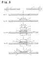
- Fig. 3 shows another example of the process for joining the films (A) according to the present invention.
- an overlapping portion (c1)5 is formed in Step (I) and Step (II).
- Step (III) the central portion (c3)11 of each overlapping portion (c2)10 wherein each part of film (B) overlaps each part of the films (A) is hot-pressed by using a comb type upper heater 9 at a temperature of from -5°C to +20°C with respect to the resin constituting the films to melt-bond these films (A) and (B).
- Step (IV) the overlapping portion (c1)5 is hot-pressed at a temperature of from -30°C to -5°C with respect to the melting point of the resin by using upper and lower heaters 7 to melt-bond the portion other than the central portions (c3).
- the central portions (c3) melt-bonded at a temperature of from -5°C to +20°C with respect to the melting point is referred to as high temperature melt-bonding portions 12 and the portions melt-bonded at a temperature of from -30°C to -5°C of the melting point is referred to as low temperature melt-bonding portions 13.
- the heating temperature for the central portions (c3) is preferably from 0°C to +10°C, more preferably, from 0°C to +5°C with respect to the melting point of the resin. It is preferable to use the comb type upper heater 9 to hot-press the central portions (c3). Step (III) and Step (IV) may be reversed in the order. In this case, the entirety of the overlapping portion (c1)5 is first melt-bonded at a low temperature and then, the central portions (c3) become high temperature melt-bonding portions.
- a step for cooling the melt-bonded films (A), (B) may be inserted.
- air cooling and a cooling plate may be mentioned.
- the insertion of the cooling step improves further the facilitation of releasing between the films (A) and the releasing sheet (or a transferring belt).
- Fig. 4 is a diagrammatical cross-sectional view of the hot-pressing portion of a hot-pressing machine used in a step shown in Fig. 3.
- the hot-pressing portion comprises a pair of comb type upper heater 9 and heater 7 which are used to hot-press the central portions (c3) at a temperature of from -5°C to +20°C with respect to the melting point of the resin, a pair of heaters 7 for hot-pressing the entirety of the overlapping portion at a temperature of from -30°C to -5°C with respect to the melting point of the fluororesin and a cooling plate 14, which are arranged successively from the direction of transferring the films.
- the films are transferred between releasing sheets 8.
- the applicable pressure in the hot-pressing step may be a pressure of the heater's own weight, a load may be applied to increase the pressure.
- the pressure is preferably from 0.01 to 10 MPa, more preferably, from 0.1 to 1 MPa.
- the film (B) may be a film having a non-hydrophilized surface at both surfaces or may be a film having a hydrophilized surface at its single surface. When the film having a hydrophilized surface at the single surface is used, the hot-pressing is conducted to oppose the hydrophilized surfaces of the film (B) and the films (A).
- the film (B) is preferably a film having a non-hydrophilized surface at both surfaces.
- each film (A) is preferably from 50 to 250 cm, more preferably from 110 to 160 cm because such width is the standardized width of a covering material for agricultural use.
- the thickness of the film (A) is preferably from 10 to 300 ⁇ m, more preferably from 50 to 100 ⁇ m because such range of thickness provides an excellent strength and excellent thermal conduction at the time of heating.
- the width of the film (B) is preferably from 2 to 10 cm, more preferably, from 2.5 to 6 cm, most preferably, from 3 to 5 cm because such range of width allows using a compact hot-pressing apparatus.
- the thickness of the film (B) is preferably from 30 to 300 ⁇ m, more preferably from 100 to 150 ⁇ m because such range of thickness provides a sufficient strength and excellent thermal conduction at the time of heating.
- the width of the overlapping portion of the film (B) and the films (A) is preferably from 1 to 8 cm, more preferably from 1.5 to 6 cm, most preferably from 2 to 4 cm in total. Further, the width of the overlapping portion of the film (B) to either film (A) is preferably from 0.5 to 4 cm, more preferably, from 0.75 to 3 cm, most preferably, from 1 to 2 cm.
- the width of the melt-bonding portion of the film (B) to the two films (A) is preferably from 1 to 8 cm, more preferably, from 1.5 to 6 cm, most preferably, from 2 to 4 cm in total. Further, the width of the melt-bonding portion of the film (B) to either film (A) is preferably from 0.5 to 4 cm, more preferably, from 0.75 to 3 cm, most preferably, from 1 to 2 cm. Such range of width provides a sufficient melt-bonding strength and allows using a compact hot-pressing apparatus.
- the film (B) and the films (A) are hot-pressed for melt-bonding at the entire area of the overlapping portion (c1). Further, it is preferable that the film (B) is hot-pressed so that portions having a predetermined width in opposing end portions of the film (B) are not melt-bonded. Further, it is more preferable that the hot-pressing is conducted so that there exist a non-melt-bonded portion having a predetermined width from the butting portion of each film (A) and non-melt-bonded portions having a predetermined width at both sides of the film (B) as shown in Fig 1.
- the width of the non-melt-bonded portion of the both sides of the film (B) and the butting portion of each film (A) is preferably from 0.1 to 10 mm, more preferably, from 0.3 to 5 mm, most preferably, from 0.5 to 3 mm.
- a wide film having a width of from 1 to 150m can be obtained by joining two or more films (A), by repeating at least once the above-mentioned film joining method.
- a wide film having a width of from 8 to 60m is preferred because its having excellent handling property or the like.
- the covering material for agricultural use is formed by using preferably a wide film having a width of from 1 to 150m, more preferably, a wide film having a width of from 8 to 60m.
- the films (A) and the film (B) in the present invention are preferably a fluororesin film or a polyolefin film.
- the fluororesin film may, for example, be a film made of ETFE, a tetrafluoroethylene/perfluoro(alkyl vinyl ether) copolymer (hereinbelow, referred to as PFA), a tetrafluoroethylene/hexafluoropropylene copolymer (hereinbelow, referred to as FEP), polychlorotrifluoroethylene (CTFE), polyvinylidene fluoride (PVDF), or polyvinyl fluoride.
- ETFE tetrafluoroethylene/perfluoro(alkyl vinyl ether) copolymer
- FEP a tetrafluoroethylene/hexafluoropropylene copolymer
- CTFE polychlorotrifluoroethylene
- PVDF polyvinylidene fluoride
- it is a film made of ETFE, PFA or FEP, more preferably, of ETFE.
- ETFE is preferably comprised of a copolymer of tetrafluoroethylene(hereinbelow, referred to as TFE) and ethylene(hereinbelow, referred to as E) and a copolymer of TFE, E and other monomer.
- CH 2 CHR f is preferred wherein R f is preferably a perfluoroalkyl group having from 3 to 6 carbon atoms, and C 4 F 9 is most preferable.
- the molar ratio of the polymerized unit based on TFE/the polymerized unit based on E is preferably from 70/30 to 30/70. It is preferably from 65/35 to 40/60, most preferably, from 60/40 to 45/55.
- the content of the polymerized unit based on the other comonomer is preferably from 0.01 to 30 mol% per the total number of mols of the polymerized units based on TFE and ethylene. It is more preferably from 0.05 to 15 mol%, and most preferably from 0.1 to 10 mol%.
- the polyolefin film in the present invention may, for example, be a film made of a polyethylene, an ethylene/vinyl acetate copolymer, a polypropylene or an ethylene/propylene copolymer, or a film made of a laminate comprising a polyethylene and an ethylene/vinyl acetate copolymer. It is preferably a film made of a polyethylene or an ethylene/vinyl acetate copolymer, or a film made of a laminate comprising a polyethylene and an ethylene/vinyl acetate copolymer, more preferably, a film made of a polyethylene or an ethylene/vinyl acetate copolymer.
- the wet method may be a method for coating a solution of hydrophilic substance with a roller, a method for coating the solution with a spray, a method for coating the solution with a blush or a method for coating the solution with a coating equipment.
- the method for coating the solution of hydrophilic substance with a coating equipment or the method for coating the solution with a spray is used.
- the dry method may be a sputtering method, a vacuum deposition method, a CVD method or an ion plating method, using a hydrophilic substance.
- the sputtering method for sputtering a hydrophilic substance is used because it increases productivity and maintains a hydrophilic effect for a long time.
- the hydrophilic substance may, for example, be a colloid sol of inorganic material such as SiO 2 or Al 2 O 3 , polyvinyl alcohol, a hydrophilic resin such as an acrylic acid or an oxide of metal such as Si, Sn, Ti, Nb, Al or Zn.
- a sputtering method or sputtering an oxide of metal such as Si, Sn or Ti it is preferable to use a sputtering method or sputtering an oxide of metal such as Si, Sn or Ti. In this case, it is further preferable to use an oxide of metal such as Si and/or Sn.
- the covering material for agricultural use of the present invention has an excellent anti-drop property because the above-mentioned hydrophilization is carried out.
- water drops flow easily even in a case that moisture in the house condenses on the inner surface of the house made of the film whereby there is little influence to the growth of crops due to the falling of water drops to the crops.
- the overlapping portion can sufficiently be melt-bonded, there is little possibility of causing the peeling of the melt-bonding portion, and the invasion of water and dust into the agricultural house can be prevented.
- a wide film having a width of from 1 to 150m formed by joining films according to the joining method of the present invention can preferably be used for a covering material for agricultural use. Further, it can also be applied to, for example, material for a tent, a bag or a waterproof sheet.
- ETFE films (a1) manufactured by Asahi Glass Company, Limited, AFLEX® film, melting point: 260°C
- AFLEX® film melting point: 260°C
- These films were disposed to align non-hydrophilized surfaces so as to butt each one end portion.
- an ETFE film (b1) manufactured by Asahi Glass Company, Limited, AFLEX® film
- AFLEX® film having a thickness of 150 ⁇ m and a width of 3.3 cm and having no hydrophilized surface
- the width of the overlapping portion at each part of the two ETFE films (a1) was 1.65 cm.
- Releasing sheets were overlaid on opposing surfaces of the overlapping portion and the overlapping portion was pressed and melt-bonded at 260°C by using a hot-pressing machine having heaters of 3 cm wide.
- each portion having a width of 1.5 mm extending from both ends of the ETFE film (b1) was not melt-bonded to each of the ETFE films (a1) and the central portion having a width of 3 cm of the film (b1) was melt-bonded.
- the peel strength of the melt-bonded portion was 2.0 kg/10 mm which showed a strong melt-bonding strength.
- Two ETFE films (a2) (manufactured by Asahi Glass Company, Limited, AFLEX® film, melting point: 260°C) having a thickness of 100 ⁇ m and a width of 1m, each having a single surface as a hydrophilized surface composed of a SiO 2 /SnO 2 (50/50 in mass percentage) having a thickness of 0.05 ⁇ m formed by a sputtering method, were prepared. These films were disposed to align non-hydrophilized surfaces so as to butt each one end portion. Then, the same ETFE film (b1) as used in Example 1 was overlaid on the two ETFE films (a2) at a side of non-hydrophilized surface so as to bridge the butting portion.
- the width of the overlapping portion at each part of the two ETFE films (a2) was 1.65 cm. Releasing sheets were overlaid on opposing surfaces of the overlapping portion and the overlapping portion was pressed and melt-bonded at 265°C by using a hot-pressing machine having heaters of 3 cm wide. It was found that each portion having a width of 1.5 mm extending from both ends of the ETFE film (b1) was not melt-bonded to each of the ETFE films (a2) and the central portion having a width of 3 cm of the film (b1) was melt-bonded. The peel strength of the melt-bonded portion was 2.5 kg/10 mm which showed a strong melt-bonding strength.
- Two ETFE films (a3) (manufactured by Asahi Glass Company, Limited, AFLEX® film, melting point: 260°C) having a thickness of 60 ⁇ m and a width of 1m, each having a single surface as a hydrophilized surface comprising a layer of SiO 2 /Al 2 O 3 having a thickness of 0.3 ⁇ m formed by coating a mixed solution of a SiO 2 sol and an Al 2 O 3 sol with a coating equipment, were prepared. These films were disposed to align non-hydrophilized surfaces so as to butt each one end portion.
- the same ETFE film (b1) as used in Example 1 was overlaid on the two ETFE films (a3) at a side of non-hydrophilized surface so as to bridge the butting portion.
- the width of the overlapping portion at each part of the two ETFE films (a3) was 1.65 cm.
- Releasing sheets were overlaid on opposing surfaces of the overlapping portion and the overlapping portion was pressed and melt-bonded at 260°C by using a hot-pressing machine having heaters of 3 cm wide. It was found that each portion having a width of 1.5 mm extending from both ends of the ETFE film (b1) was not melt-bonded to each of the ETFE films (a3) and the central portion having a width of 3 cm of the film (b1) was melt-bonded.
- the peeling strength of the melt-bonded portion was 2.0 kg/10 mm which showed a strong melt-bonding strength.
- the same two ETFE films (a1) as used in Example 1 were prepared and the hydrophilized surface of either ETFE film (a1) and the non-hydrophilized surface of the other ETFE film (a1) were overlapped each other with a width of 3 cm from each end portion of the films.
- Releasing sheets were overlaid on opposing surfaces of the overlapping portion and the overlapping portion was pressed and melt-bonded at 260°C by using a hot-pressing machine having heaters of 3 cm wide.
- the peeling strength of the melt-bonded portion was 0.4 kg/10 mm which showed an insufficient melt-bonding strength.
- Example 2 The same two ETFE films (a2) as used in Example 2 were prepared and the hydrophilized surface of either ETFE film (a2) and the non-hydrophilized surface of the other ETFE film (a2) were overlapped each other with a width of 3 cm from each end portion of the films. Releasing sheets were overlaid on opposing surfaces of the overlapping portion and the overlapping portion was pressed and melt-bonded at 260°C by using a hot-pressing machine having heaters of 3 cm wide. The peeling strength of the melt-bonded portion was 0.4 kg/10 mm which showed an insufficient melt-bonding strength.
- Two polyolefin films (a4) (manufactured by Mitsubishi Chemical MKV Company, super solar anti-drop film) having a thickness of 100 ⁇ m and a width of 1m, each having a single surface as a hydrophilized surface were prepared. These films were disposed to align non-hydrophilized surfaces so as to butt each one end portion. Then, a polyolefin film (b2) having a thickness of 150 ⁇ m and a width of 3.3 cm having no hydrophilized surface was overlaid on the two polyolefin films (a4) at a side of non-hydrophilized surface so as to bridge the butting portion. The width of the overlapping portion at each part of the two polyolefin films (a4) was 1.65 cm.
- Releasing sheets were overlaid on opposing surfaces of the overlapping portion and the overlapping portion was pressed and melt-bonded at 120°C by using a hot-pressing machine having heaters of 3 cm wide. It was found that each portion having a width of 1.5 mm extending from both ends of the polyolefin film (b2) was not melt-bonded to each of the polyolefin films (a4) and the central portion having a width of 3 cm of the film (b2) was melt-bonded. The peeling strength of the melt-bonded portion was 2.0 kg/10 mm which showed a strong melt-bonding strength.
- An ETFE film (b1) having a single surface as a hydrophilized surface was overlaid on two ETFE films (a1) in the same manner as Example 1.
- the width of the overlapping portion at each part of the two ETFE films (a1) was the same.
- Releasing sheets were overlaid on vertically opposing surfaces of the overlapping portion and the overlapping portion was hot-pressed at 260°C with a comb type upper heater 9 to form two high temperature melt-bonding portions.
- Fig. 5 is a diagrammatical cross-sectional view of the comb type upper heater 9, a lower heater 7 and the films (A)1 and the film (B)4 to be bonded by hot-pressing.
- the dimensions of the central portion and hot-pressing portions were 12 mm and 6 mm respectively.
- the width of the comb type upper heater 9 and the width of the lower heater 7 were 30 mm. These heaters 9, 7 were arranged so as to meet the center of width of the heaters to the butting portion of the ETFE films (a1).
- the upper and lower heaters each having a width of 30 mm were arranged so as to meet the center of width of these heaters to the center of the butting portion of the two films (a1) and the films (A)(B) were hot-pressed at 250°C which was lower than that for the high temperature melt-bonding portions.
- the upper and lower heaters each having a width of 30 mm were arranged so as to meet the center of width of these heaters to the center of the butting portion of the two films (a1) and the films (A)(B) were hot-pressed at 250°C which was lower than that for the high temperature melt-bonding portions.
- An ETFE film (b1) was overlaid on two ETFE films (a2) having a single surface as a hydrophilized surface in the same manner as Example 2.
- the width of the overlapping portion at each part of the two ETFE films (a2) was the same.
- the overlapping portion was hot-pressed in the same manner as Example 5 to form high temperature melt-bonding portions melt-bonded at 260°C and low temperature melt-bonding portions melt-bonded at 250°C.
- a joined film wherein each portion having a width of 1.5 mm extending from both ends of the ETFE film (b1) was not bonded to each of the ETFE films (a2) and the central portion having a width of 3 cm of the film (b1) was melt-bonded to the films (a2) was obtained.
- the peel strength of the melt-bonded portion was 2.4 kg/10 mm (width) which showed a strong melt-bonding strength. Further, the tear strength was 1.0N which showed a high tear resistance.
- An ETFE film (b1) was overlaid on two ETFE films (a3) having a single surface as a hydrophilized surface in the same manner as Example 3.
- the width of the overlapping portion at each part of the two ETFE films (a3) was the same.
- the overlapping portion was hot-pressed in the same manner as Example 5 to form high temperature melt-bonding portions melt-bonded at 260°C and low temperature melt-bonded portions melt-bonded at 250°C.
- a joined film wherein each portion having a width of 1.5 mm extending from both ends of the ETFE films (b1) was not bonded to each of the films (a3) and the central portion having a width of 3 cm of the film (b1) was melt-bonded to the films (a3) was obtained.
- the peel strength of the melt-bonded portion was 2.1 kg/10 mm (width) which showed a strong melt-bonding strength.
- the tear strength was 1.1N which showed a high tear resistance.
- a wide film can easily be obtained from films having a hydrophilized surface at their single surface.
- the obtained wide film has an excellent bonding strength in the melt-bonded portion of the films and an excellent tear strength.
- the obtained wide film is suitably applicable to a covering material for agricultural use.
- the covering material for agricultural use has an excellent anti-drop property. Since water drops caused by the condensation of water in the house easily flows, the covering material has a good permeability to light and there is little possibility of falling of water drops on crops.
Landscapes
- Engineering & Computer Science (AREA)
- Mechanical Engineering (AREA)
- Physics & Mathematics (AREA)
- Thermal Sciences (AREA)
- High Energy & Nuclear Physics (AREA)
- Plasma & Fusion (AREA)
- Life Sciences & Earth Sciences (AREA)
- Materials Engineering (AREA)
- Chemical & Material Sciences (AREA)
- Soil Sciences (AREA)
- Environmental Sciences (AREA)
- Protection Of Plants (AREA)
- Lining Or Joining Of Plastics Or The Like (AREA)
- Laminated Bodies (AREA)
- Greenhouses (AREA)
- Manufacture Of Macromolecular Shaped Articles (AREA)
Abstract
Description
- The present invention relates to a film joining method, a wide film produced by the joining method and a covering material for agricultural use made of the wide film.
- A wide film is generally used as a covering material for agricultural use. A film produced in an industrial scale, such as a vinyl chloride film for agricultural use (hereinbelow, referred to as the agricultural film) has a width of from 1 to 4m. Such film is insufficient for the covering material for agricultural use because of its width. Accordingly, a film having a larger width obtained by joining these films is used as a covering material for agricultural use. As film joining methods for these films, a joining method that two films are overlapped at their one end portion and the overlapping portion is hot-pressed is adopted.
- Even in a case of using a fluororesin film made of fluororesin such as an ethylene/tetrafluoroethylene copolymer (hereinbelow, referred to as ETFE), or a polyolefin film composed of polyolefin such as polyethylene or an ethylene/vinyl acetate copolymer, wherein the film does not have a hydrophilized surface, the joining method that two films are overlapped at each end portion and the overlapped portion is hot-pressed can be adopted in the same manner as the agricultural film.
- However, when a film without having a hydrophilized surface is used for setting-up an agricultural house or the like, the light permeability of the film tends to decrease due to water drops resulted from water condensation at an inner side of the set-up film or to prevent the growth of crops because the water drops fall on the crops from the film. The above-mentioned problem is generally solved by conducting hydrophilization to the film used as the covering material for agricultural use so as to provide an anti-drop property to the film.
- As the agricultural film, a film formed by shaping polyvinyl chloride in which a hydrophilization agent is mixed is generally used so that a hydrophilization effect can be presented. With the film containing the hydrophilization agent, a wide film can be formed easily by overlapping each end part of the films and hot-pressing the overlapping portion so that the overlapping portion is melt-bonded.
- In a case of using the fluororesin, a method for mixing a hydrophilization agent cannot be adopted because the decomposition of an industrially available hydrophilization agent is caused since the fluororesin has a high molding temperature. Accordingly, a hydrophilization method wherein a hydrophilic substance is coated on a surface of the fluororesin film is adopted. In such fluororesin film having a hydrophilized surface, however, an overlapping portion cannot be melt-bonded sufficiently when the films are laid to overlap each other and the overlapping portion is hot-pressed to bond the films, because of the presence of the hydrophilized surface.
- As methods for solving the above-mentioned problems, there is a method that when a surface of a film is subjected to hydrophilization, an end portion including its neighboring portion is masked to form a portion where the hydrophilic substance is not applied; this portion is overlapped with a non-hydrophilized surface, and the overlapping portion is hot-pressed for melt-bonding.
- However, this method has a complicated manufacturing process because a masking step is additional whereby an increased cost is caused in order to form the wide film.
- It is an object of the present invention to provide a method for joining films (A) having a hydrophilized surface at their single surface.
- It is another object of the present invention to provide a wide film obtained by repeating the above-mentioned method at least once and a covering method for agricultural use formed by using the wide film.
- In accordance with the present invention, there is provided a film joining method which comprises disposing two films (A) having a hydrophilized surface at their single surface to align the hydrophilized surfaces so as to butt each one end portion; overlaying a film (B) on a side of non-hydrophilized surface of the films (A) so as to bridge the butting portion, and hot-pressing the overlapping portion (c1) to join the two films (A).
- Further, the present invention is to provide a wide film having a width of 1 to 150m formed by joining at least two films (A) which is characterized by repeating at least once the above-mentioned joining method, and a covering material formed by using the wide film.
- In drawings:
- Fig. 1 is a diagrammatical view in cross section of films (A) and a film (B) joined by the film joining method of the present invention;
- Fig. 2 is a diagram showing an example of the process for joining films (A) according to the film joining method of the present invention;
- Fig. 3 is a diagram showing another example of the process for joining films (A) according to the film joining method of the present invention;
- Fig. 4 is a cross-sectional view of a hot-pressing portion of a hot-pressing machine used in a step in Fig. 3; and
- Fig. 5 is a diagrammatical sectional view of a comb type upper heater, a lower heater and films (A) and a film (B) to be hot-pressed by the heaters.
-
- Preferred embodiments of the film joining method of the present invention will be described with reference to the drawing.
- Fig. 1 is a diagrammatical cross-sectional view of films (A) having a hydrophilized surface at their single surface. Films (A)1 and a film (B)4 are melt-bonded at a melt-bonding
portion 6 on a side of non-hydrophilized surface of the films (A) whereby two films (A) are joined by the aid of the film (B). In this specification, "join" means connection by melt-bonding. - An example of a joining step for the films (A) is shown in Fig. 2. In Step (I), two films (A) having a
hydrophilized surface 2 at their single surface are disposed to align the hydrophilized surfaces so as to butt each one end portion. Then, in Step (II), a film (B)4 is overlaid on each end part of the films (A) on a side ofnon-hydrophilized surface 3 formed on the films so as to bridge the butting portion to thereby form an overlapping portion (c1)5. In Step (III), the overlapping portion (c1)5 is hot-pressed with upper andlower heaters 7 of a hot-pressing machine whereby a melt-bondedportion 6 is formed and the two films (A) are connected by the aid of the film (B). - In Step (III), releasing
sheets 8 are preferably used in order to prevent the adhesion of the films (A) and the film (B) to the upper andlower heaters 7 of the hot-pressing machine. Further, the opposed end portions of the two films (A) may be butted each other or may not be in mutual contact so as to have a gap between the films (A). When there is a gap, the distance is preferably from 0.01 to 88 mm, more preferably, from 0.05 to 50 mm, most preferably, from 0.1 to 30 mm. - In the joining method of the present invention, the two films (A) having a hydrophilized surface at their single surface are disposed to align the hydrophilized surfaces so as to butt each one end portion; a single film (B) is overlaid on the films (A) on a side of non-hydrophilized surface of the films so as to bridge the butting portion, and the overlapping portion (c1) is hot-pressed to join the two films (A).
- It is preferable to hot-press the overlapping portion (c1) at a temperature of from -30°C to +20°C with respect to the melting point of a resin constituting the films (A) and the film (B). The heating temperature for hot-pressing is more preferably from -15°C to +20°C, more preferably, from -20°C to +10°C, further more preferably, from -15°C to +5°C. The most preferable range is from 0°C to +5°C with respect to the melting point of the resin constituting the films.
- It is also preferable that the central portion (c3) of a part of film (B) which is overlaid on either film (A) in the overlapping portion (c1) and the central portion (c3) of a part of film (B) which is overlaid on the other film (A) in the overlapping portion (c1) are hot-pressed at a temperature of -5°C to +20°C with respect to the melting point of the resin constituting the films (A) and the film (B), and then, the overlapping portion (c1) is hot-pressed at a temperature of from -30°C to -5°C with respect to the melting point of the resin.
- Fig. 3 shows another example of the process for joining the films (A) according to the present invention. In the same manner as in Fig. 2, an overlapping portion (c1)5 is formed in Step (I) and Step (II). Then, in Step (III) the central portion (c3)11 of each overlapping portion (c2)10 wherein each part of film (B) overlaps each part of the films (A) is hot-pressed by using a comb type
upper heater 9 at a temperature of from -5°C to +20°C with respect to the resin constituting the films to melt-bond these films (A) and (B). - Then, in Step (IV), the overlapping portion (c1)5 is hot-pressed at a temperature of from -30°C to -5°C with respect to the melting point of the resin by using upper and
lower heaters 7 to melt-bond the portion other than the central portions (c3). Hereinbelow, the central portions (c3) melt-bonded at a temperature of from -5°C to +20°C with respect to the melting point is referred to as high temperature melt-bondingportions 12 and the portions melt-bonded at a temperature of from -30°C to -5°C of the melting point is referred to as low temperature melt-bondingportions 13. - The heating temperature for the central portions (c3) is preferably from 0°C to +10°C, more preferably, from 0°C to +5°C with respect to the melting point of the resin. It is preferable to use the comb type
upper heater 9 to hot-press the central portions (c3). Step (III) and Step (IV) may be reversed in the order. In this case, the entirety of the overlapping portion (c1)5 is first melt-bonded at a low temperature and then, the central portions (c3) become high temperature melt-bonding portions. - Further, after the films are hot-pressed for melt-bonding, a step for cooling the melt-bonded films (A), (B) may be inserted. For example, air cooling and a cooling plate may be mentioned. The insertion of the cooling step improves further the facilitation of releasing between the films (A) and the releasing sheet (or a transferring belt).
- Fig. 4 is a diagrammatical cross-sectional view of the hot-pressing portion of a hot-pressing machine used in a step shown in Fig. 3. The hot-pressing portion comprises a pair of comb type
upper heater 9 andheater 7 which are used to hot-press the central portions (c3) at a temperature of from -5°C to +20°C with respect to the melting point of the resin, a pair ofheaters 7 for hot-pressing the entirety of the overlapping portion at a temperature of from -30°C to -5°C with respect to the melting point of the fluororesin and acooling plate 14, which are arranged successively from the direction of transferring the films. In a hot-pressing step, the films are transferred between releasingsheets 8. Although the applicable pressure in the hot-pressing step may be a pressure of the heater's own weight, a load may be applied to increase the pressure. The pressure is preferably from 0.01 to 10 MPa, more preferably, from 0.1 to 1 MPa. - The film (B) may be a film having a non-hydrophilized surface at both surfaces or may be a film having a hydrophilized surface at its single surface. When the film having a hydrophilized surface at the single surface is used, the hot-pressing is conducted to oppose the hydrophilized surfaces of the film (B) and the films (A). The film (B) is preferably a film having a non-hydrophilized surface at both surfaces.
- The width of each film (A) is preferably from 50 to 250 cm, more preferably from 110 to 160 cm because such width is the standardized width of a covering material for agricultural use. The thickness of the film (A) is preferably from 10 to 300 µm, more preferably from 50 to 100 µm because such range of thickness provides an excellent strength and excellent thermal conduction at the time of heating.
- The width of the film (B) is preferably from 2 to 10 cm, more preferably, from 2.5 to 6 cm, most preferably, from 3 to 5 cm because such range of width allows using a compact hot-pressing apparatus. The thickness of the film (B) is preferably from 30 to 300 µm, more preferably from 100 to 150 µm because such range of thickness provides a sufficient strength and excellent thermal conduction at the time of heating.
- The width of the overlapping portion of the film (B) and the films (A) is preferably from 1 to 8 cm, more preferably from 1.5 to 6 cm, most preferably from 2 to 4 cm in total. Further, the width of the overlapping portion of the film (B) to either film (A) is preferably from 0.5 to 4 cm, more preferably, from 0.75 to 3 cm, most preferably, from 1 to 2 cm.
- The width of the melt-bonding portion of the film (B) to the two films (A) is preferably from 1 to 8 cm, more preferably, from 1.5 to 6 cm, most preferably, from 2 to 4 cm in total. Further, the width of the melt-bonding portion of the film (B) to either film (A) is preferably from 0.5 to 4 cm, more preferably, from 0.75 to 3 cm, most preferably, from 1 to 2 cm. Such range of width provides a sufficient melt-bonding strength and allows using a compact hot-pressing apparatus.
- It is preferable that the film (B) and the films (A) are hot-pressed for melt-bonding at the entire area of the overlapping portion (c1). Further, it is preferable that the film (B) is hot-pressed so that portions having a predetermined width in opposing end portions of the film (B) are not melt-bonded. Further, it is more preferable that the hot-pressing is conducted so that there exist a non-melt-bonded portion having a predetermined width from the butting portion of each film (A) and non-melt-bonded portions having a predetermined width at both sides of the film (B) as shown in Fig 1. The width of the non-melt-bonded portion of the both sides of the film (B) and the butting portion of each film (A) is preferably from 0.1 to 10 mm, more preferably, from 0.3 to 5 mm, most preferably, from 0.5 to 3 mm.
- In the present invention, a wide film having a width of from 1 to 150m can be obtained by joining two or more films (A), by repeating at least once the above-mentioned film joining method. A wide film having a width of from 8 to 60m is preferred because its having excellent handling property or the like.
- In the present invention, the covering material for agricultural use is formed by using preferably a wide film having a width of from 1 to 150m, more preferably, a wide film having a width of from 8 to 60m.
- The films (A) and the film (B) in the present invention are preferably a fluororesin film or a polyolefin film.
- The fluororesin film may, for example, be a film made of ETFE, a tetrafluoroethylene/perfluoro(alkyl vinyl ether) copolymer (hereinbelow, referred to as PFA), a tetrafluoroethylene/hexafluoropropylene copolymer (hereinbelow, referred to as FEP), polychlorotrifluoroethylene (CTFE), polyvinylidene fluoride (PVDF), or polyvinyl fluoride. Preferably, it is a film made of ETFE, PFA or FEP, more preferably, of ETFE.
- ETFE is preferably comprised of a copolymer of tetrafluoroethylene(hereinbelow, referred to as TFE) and ethylene(hereinbelow, referred to as E) and a copolymer of TFE, E and other monomer.
- The other monomer may, for example, be a fluoroolefin such as chlorotrifluoroethylene, hexafluoropropylene, perfluoro(alkyl vinyl ether), a fluoroolefin such as vinylidene fluoride, a polyfluoroalkylethylene such as CH2=CHRf (wherein Rf represents a polyfluoroalkyl group having from 1 to 8 carbon atoms, the same definition is used below) or CH2=CFRf, or a polyfluoroalkyl trifluorovinyl ether such as CF2=CFOCH2Rf. These monomers may be used alone or in combination of two or more of them.
- In particular, CH2=CHRf is preferred wherein Rf is preferably a perfluoroalkyl group having from 3 to 6 carbon atoms, and C4F9 is most preferable.
- As the composition of ETFE, the molar ratio of the polymerized unit based on TFE/the polymerized unit based on E is preferably from 70/30 to 30/70. It is preferably from 65/35 to 40/60, most preferably, from 60/40 to 45/55.
- When it contains the polymerized unit based on the other comonomer, the content of the polymerized unit based on the other comonomer is preferably from 0.01 to 30 mol% per the total number of mols of the polymerized units based on TFE and ethylene. It is more preferably from 0.05 to 15 mol%, and most preferably from 0.1 to 10 mol%.
- The polyolefin film in the present invention may, for example, be a film made of a polyethylene, an ethylene/vinyl acetate copolymer, a polypropylene or an ethylene/propylene copolymer, or a film made of a laminate comprising a polyethylene and an ethylene/vinyl acetate copolymer. It is preferably a film made of a polyethylene or an ethylene/vinyl acetate copolymer, or a film made of a laminate comprising a polyethylene and an ethylene/vinyl acetate copolymer, more preferably, a film made of a polyethylene or an ethylene/vinyl acetate copolymer.
- As the method for forming a hydrophilized surface in order to form the film (A) having a hydrophilized surface at its single surface used in the present invention, there are a wet method and a dry method. The wet method may be a method for coating a solution of hydrophilic substance with a roller, a method for coating the solution with a spray, a method for coating the solution with a blush or a method for coating the solution with a coating equipment. Preferably, the method for coating the solution of hydrophilic substance with a coating equipment or the method for coating the solution with a spray is used.
- The dry method may be a sputtering method, a vacuum deposition method, a CVD method or an ion plating method, using a hydrophilic substance. Preferably, the sputtering method for sputtering a hydrophilic substance is used because it increases productivity and maintains a hydrophilic effect for a long time.
- The hydrophilic substance may, for example, be a colloid sol of inorganic material such as SiO2 or Al2O3, polyvinyl alcohol, a hydrophilic resin such as an acrylic acid or an oxide of metal such as Si, Sn, Ti, Nb, Al or Zn.
- In particular, it is preferable to use a sputtering method or sputtering an oxide of metal such as Si, Sn or Ti. In this case, it is further preferable to use an oxide of metal such as Si and/or Sn.
- The covering material for agricultural use of the present invention has an excellent anti-drop property because the above-mentioned hydrophilization is carried out. In an agricultural house formed by setting-up the covering material for agricultural use of the present invention, water drops flow easily even in a case that moisture in the house condenses on the inner surface of the house made of the film whereby there is little influence to the growth of crops due to the falling of water drops to the crops.
- Further, in the film joining method of the present invention, since the overlapping portion can sufficiently be melt-bonded, there is little possibility of causing the peeling of the melt-bonding portion, and the invasion of water and dust into the agricultural house can be prevented.
- A wide film having a width of from 1 to 150m formed by joining films according to the joining method of the present invention can preferably be used for a covering material for agricultural use. Further, it can also be applied to, for example, material for a tent, a bag or a waterproof sheet.
- Now, the present invention will be described in further detail with reference to Examples. However, it should be understood that the present invention is by no means restricted to such specific examples.
- Two ETFE films (a1) (manufactured by Asahi Glass Company, Limited, AFLEX® film, melting point: 260°C) having a thickness of 60 µm and a width of 1m, each having a single surface as a hydrophilized surface composed of a SiO2/SnO2 (50/50 in mass percentage) having a thickness of 0.05 µm formed by a sputtering method, were prepared. These films were disposed to align non-hydrophilized surfaces so as to butt each one end portion. Then, an ETFE film (b1) (manufactured by Asahi Glass Company, Limited, AFLEX® film) having a thickness of 150 µm and a width of 3.3 cm and having no hydrophilized surface was overlaid on the two ETFE films (a1) at a side of non-hydrophilized surface so as to bridge the butting portion. The width of the overlapping portion at each part of the two ETFE films (a1) was 1.65 cm. Releasing sheets were overlaid on opposing surfaces of the overlapping portion and the overlapping portion was pressed and melt-bonded at 260°C by using a hot-pressing machine having heaters of 3 cm wide. It was found that each portion having a width of 1.5 mm extending from both ends of the ETFE film (b1) was not melt-bonded to each of the ETFE films (a1) and the central portion having a width of 3 cm of the film (b1) was melt-bonded. The peel strength of the melt-bonded portion was 2.0 kg/10 mm which showed a strong melt-bonding strength.
- Two ETFE films (a2) (manufactured by Asahi Glass Company, Limited, AFLEX® film, melting point: 260°C) having a thickness of 100 µm and a width of 1m, each having a single surface as a hydrophilized surface composed of a SiO2/SnO2 (50/50 in mass percentage) having a thickness of 0.05 µm formed by a sputtering method, were prepared. These films were disposed to align non-hydrophilized surfaces so as to butt each one end portion. Then, the same ETFE film (b1) as used in Example 1 was overlaid on the two ETFE films (a2) at a side of non-hydrophilized surface so as to bridge the butting portion. The width of the overlapping portion at each part of the two ETFE films (a2) was 1.65 cm. Releasing sheets were overlaid on opposing surfaces of the overlapping portion and the overlapping portion was pressed and melt-bonded at 265°C by using a hot-pressing machine having heaters of 3 cm wide. It was found that each portion having a width of 1.5 mm extending from both ends of the ETFE film (b1) was not melt-bonded to each of the ETFE films (a2) and the central portion having a width of 3 cm of the film (b1) was melt-bonded. The peel strength of the melt-bonded portion was 2.5 kg/10 mm which showed a strong melt-bonding strength.
- Two ETFE films (a3) (manufactured by Asahi Glass Company, Limited, AFLEX® film, melting point: 260°C) having a thickness of 60 µm and a width of 1m, each having a single surface as a hydrophilized surface comprising a layer of SiO2/Al2O3 having a thickness of 0.3 µm formed by coating a mixed solution of a SiO2 sol and an Al2O3 sol with a coating equipment, were prepared. These films were disposed to align non-hydrophilized surfaces so as to butt each one end portion. Then, the same ETFE film (b1) as used in Example 1 was overlaid on the two ETFE films (a3) at a side of non-hydrophilized surface so as to bridge the butting portion. The width of the overlapping portion at each part of the two ETFE films (a3) was 1.65 cm. Releasing sheets were overlaid on opposing surfaces of the overlapping portion and the overlapping portion was pressed and melt-bonded at 260°C by using a hot-pressing machine having heaters of 3 cm wide. It was found that each portion having a width of 1.5 mm extending from both ends of the ETFE film (b1) was not melt-bonded to each of the ETFE films (a3) and the central portion having a width of 3 cm of the film (b1) was melt-bonded. The peeling strength of the melt-bonded portion was 2.0 kg/10 mm which showed a strong melt-bonding strength.
- The same two ETFE films (a1) as used in Example 1 were prepared and the hydrophilized surface of either ETFE film (a1) and the non-hydrophilized surface of the other ETFE film (a1) were overlapped each other with a width of 3 cm from each end portion of the films. Releasing sheets were overlaid on opposing surfaces of the overlapping portion and the overlapping portion was pressed and melt-bonded at 260°C by using a hot-pressing machine having heaters of 3 cm wide. The peeling strength of the melt-bonded portion was 0.4 kg/10 mm which showed an insufficient melt-bonding strength.
- The same two ETFE films (a2) as used in Example 2 were prepared and the hydrophilized surface of either ETFE film (a2) and the non-hydrophilized surface of the other ETFE film (a2) were overlapped each other with a width of 3 cm from each end portion of the films. Releasing sheets were overlaid on opposing surfaces of the overlapping portion and the overlapping portion was pressed and melt-bonded at 260°C by using a hot-pressing machine having heaters of 3 cm wide. The peeling strength of the melt-bonded portion was 0.4 kg/10 mm which showed an insufficient melt-bonding strength.
- Two polyolefin films (a4) (manufactured by Mitsubishi Chemical MKV Company, super solar anti-drop film) having a thickness of 100 µm and a width of 1m, each having a single surface as a hydrophilized surface were prepared. These films were disposed to align non-hydrophilized surfaces so as to butt each one end portion. Then, a polyolefin film (b2) having a thickness of 150 µm and a width of 3.3 cm having no hydrophilized surface was overlaid on the two polyolefin films (a4) at a side of non-hydrophilized surface so as to bridge the butting portion. The width of the overlapping portion at each part of the two polyolefin films (a4) was 1.65 cm. Releasing sheets were overlaid on opposing surfaces of the overlapping portion and the overlapping portion was pressed and melt-bonded at 120°C by using a hot-pressing machine having heaters of 3 cm wide. It was found that each portion having a width of 1.5 mm extending from both ends of the polyolefin film (b2) was not melt-bonded to each of the polyolefin films (a4) and the central portion having a width of 3 cm of the film (b2) was melt-bonded. The peeling strength of the melt-bonded portion was 2.0 kg/10 mm which showed a strong melt-bonding strength.
- An ETFE film (b1) having a single surface as a hydrophilized surface was overlaid on two ETFE films (a1) in the same manner as Example 1. The width of the overlapping portion at each part of the two ETFE films (a1) was the same. Releasing sheets were overlaid on vertically opposing surfaces of the overlapping portion and the overlapping portion was hot-pressed at 260°C with a comb type
upper heater 9 to form two high temperature melt-bonding portions. - Fig. 5 is a diagrammatical cross-sectional view of the comb type
upper heater 9, alower heater 7 and the films (A)1 and the film (B)4 to be bonded by hot-pressing. In the comb-typeupper heater 9, the dimensions of the central portion and hot-pressing portions were 12 mm and 6 mm respectively. The width of the comb typeupper heater 9 and the width of thelower heater 7 were 30 mm. Theseheaters - Then, the upper and lower heaters each having a width of 30 mm were arranged so as to meet the center of width of these heaters to the center of the butting portion of the two films (a1) and the films (A)(B) were hot-pressed at 250°C which was lower than that for the high temperature melt-bonding portions. Thus, there are obtainable two low temperature melt-bonding portions at both outer sides of the high temperature melt-bonding portions melt-bonded at 260°C. As a result, a joined film wherein each portion having a width of 1.5 mm extending from both ends of the ETFE film (b1) was not bonded to each of the ETFE films (a1) and the central portion having a width of 3 cm of the film (b1) was melt-bonded to the films (a1), was obtained. The peeling strength of the melt-bonding portion was 2.1 kg/10 mm (width) which showed a strong melt-bonding strength. The tear strength was 1.1N which showed a high tear resistance.
- An ETFE film (b1) was overlaid on two ETFE films (a2) having a single surface as a hydrophilized surface in the same manner as Example 2. The width of the overlapping portion at each part of the two ETFE films (a2) was the same. The overlapping portion was hot-pressed in the same manner as Example 5 to form high temperature melt-bonding portions melt-bonded at 260°C and low temperature melt-bonding portions melt-bonded at 250°C. As a result, a joined film wherein each portion having a width of 1.5 mm extending from both ends of the ETFE film (b1) was not bonded to each of the ETFE films (a2) and the central portion having a width of 3 cm of the film (b1) was melt-bonded to the films (a2) was obtained. The peel strength of the melt-bonded portion was 2.4 kg/10 mm (width) which showed a strong melt-bonding strength. Further, the tear strength was 1.0N which showed a high tear resistance.
- An ETFE film (b1) was overlaid on two ETFE films (a3) having a single surface as a hydrophilized surface in the same manner as Example 3. The width of the overlapping portion at each part of the two ETFE films (a3) was the same. The overlapping portion was hot-pressed in the same manner as Example 5 to form high temperature melt-bonding portions melt-bonded at 260°C and low temperature melt-bonded portions melt-bonded at 250°C. As a result, a joined film wherein each portion having a width of 1.5 mm extending from both ends of the ETFE films (b1) was not bonded to each of the films (a3) and the central portion having a width of 3 cm of the film (b1) was melt-bonded to the films (a3), was obtained. The peel strength of the melt-bonded portion was 2.1 kg/10 mm (width) which showed a strong melt-bonding strength. The tear strength was 1.1N which showed a high tear resistance.
- In accordance with the film joining method of the present invention, a wide film can easily be obtained from films having a hydrophilized surface at their single surface. The obtained wide film has an excellent bonding strength in the melt-bonded portion of the films and an excellent tear strength. Further, the obtained wide film is suitably applicable to a covering material for agricultural use. When the wide film formed according to the film joining method of the present invention is used as the covering material for agricultural use for setting-up an agricultural house, there is little possibility of causing the peeling of the melt-bonded portion and invasion of water or dust into the agricultural house can be prevented. The covering material for agricultural use has an excellent anti-drop property. Since water drops caused by the condensation of water in the house easily flows, the covering material has a good permeability to light and there is little possibility of falling of water drops on crops.
- The entire disclosures of Japanese Patent Application No. 2001-381167 filed on December 14, 2001, Japanese Patent Application No. 2002-41770 filed on February 19, 2002 and Japanese Patent Application No. 2002-318203 filed on October 31, 2002 including specifications, claims, drawings and summaries are incorporated herein by reference in their entireties.
Claims (10)
- A film joining method which comprises disposing two films(A) having a hydrophilized surface at their single surface to align the hydrophilized surfaces so as to butt each one end portion; overlaying a film (B) on a side of non-hydrophilized surface of the films (A) so as to bridge the butting portion, and hot-pressing the overlapping portion (c1) to join the two films (A).
- The joining method according to Claim 1, wherein the overlapping portion (c1) is hot-pressed at a temperature of from -30°C to +20°C with respect to the melting point of a resin constituting the films (A) and the film (B).
- The joining method according to Claim 1, wherein the central portion (c3) of a part of film (B) which is overlaid on either film (A) in the overlapping portion (c1) and the central portion (c3) of a part of film (B) which is overlaid on the other film (A) in the overlapping portion (c1) are hot-pressed at a temperature of -5°C to +20°C with respect to the melting point of a resin constituting the films (A) and the film (B), and then, the overlapping portion (c1) is hot-pressed at a temperature of from -30°C to +20°C with respect to the melting point of the resin.
- The joining method according to any one of Claims 1 to 3, wherein the films (A) and the film (B) are made of a fluororesin film or a polyolefin film.
- The joining method according to any one of Claims 1 to 4, wherein the films (A) and the film (B) are a film made of an ethylene/tetrafluoroethylene copolymer.
- The joining method according to any one of Claims 1 to 5, wherein the width of the film (A) is from 50 to 250 cm.
- The joining method according to any one of Claims 1 to 6, wherein the width of the film (B) is from 2 to 10 cm.
- The joining method according to any one of Claims 1 to 7, wherein the hydrophilized surface of the film (A) is a hydrophilized surface formed by sputtering a metal oxide.
- A wide film having a width of 1 to 150m formed by joining at least two films (A) which is characterized by repeating at least once the joining method described in any one of Claims 1 to 8.
- A covering material for agricultural use which comprises the wide film described in Claim 9.
Applications Claiming Priority (6)
| Application Number | Priority Date | Filing Date | Title |
|---|---|---|---|
| JP2001381167 | 2001-12-14 | ||
| JP2001381167 | 2001-12-14 | ||
| JP2002041770 | 2002-02-19 | ||
| JP2002041770 | 2002-02-19 | ||
| JP2002318203A JP4063049B2 (en) | 2001-12-14 | 2002-10-31 | Film bonding method and method for producing wide film using the method |
| JP2002318203 | 2002-10-31 |
Publications (2)
| Publication Number | Publication Date |
|---|---|
| EP1319495A1 true EP1319495A1 (en) | 2003-06-18 |
| EP1319495B1 EP1319495B1 (en) | 2005-03-16 |
Family
ID=27347957
Family Applications (1)
| Application Number | Title | Priority Date | Filing Date |
|---|---|---|---|
| EP02027592A Expired - Lifetime EP1319495B1 (en) | 2001-12-14 | 2002-12-10 | Film joining method, a wide film produced by the joining method and a covering material for agricultural use made of the wide film |
Country Status (8)
| Country | Link |
|---|---|
| US (1) | US6841028B2 (en) |
| EP (1) | EP1319495B1 (en) |
| JP (1) | JP4063049B2 (en) |
| KR (1) | KR100928862B1 (en) |
| CN (1) | CN1315636C (en) |
| AT (1) | ATE290950T1 (en) |
| DE (1) | DE60203250T2 (en) |
| TW (1) | TWI262844B (en) |
Cited By (3)
| Publication number | Priority date | Publication date | Assignee | Title |
|---|---|---|---|---|
| EP1486316A1 (en) * | 2002-03-20 | 2004-12-15 | Asahi Glass Company Ltd. | Method of bonding fluororesin films and fluororesin film |
| EP1750155A1 (en) * | 2005-08-01 | 2007-02-07 | ibidi GmbH | Sample chamber and method of fabrication |
| EP4091437A1 (en) | 2021-05-20 | 2022-11-23 | Hueck Folien Gesellschaft m.b.H. | Method for producing a hydrophilic coating on a fluoropolymer material |
Families Citing this family (15)
| Publication number | Priority date | Publication date | Assignee | Title |
|---|---|---|---|---|
| JP5011726B2 (en) * | 2003-08-01 | 2012-08-29 | 旭硝子株式会社 | Coating material for solar thermal power generation system and solar thermal power generation system extending the same |
| USRE44893E1 (en) | 2004-03-26 | 2014-05-13 | Hanwha Azdel, Inc. | Fiber reinforced thermoplastic sheets with surface coverings |
| AT413385B (en) * | 2004-09-13 | 2006-02-15 | Amag Rolling Gmbh | METHOD OF APPLYING A PROTECTIVE STRIP TO A CATHODE SHEET FOR ELECTROLYTICALLY OBTAINING A METAL FROM AN ELECTROLYTE LIQUID |
| US7482048B2 (en) * | 2005-04-22 | 2009-01-27 | Azdel, Inc. | Composite thermoplastic sheets including an integral hinge |
| JP2007030346A (en) * | 2005-07-27 | 2007-02-08 | Sanzen Kako Kk | Film for agriculture |
| CN1962240B (en) * | 2005-11-08 | 2010-05-05 | 纬创资通股份有限公司 | Hot melt fixing structure and its assembling method |
| JP4965213B2 (en) * | 2006-09-29 | 2012-07-04 | ニチアス株式会社 | Method for welding modified polytetrafluoroethylene molded body |
| JP4707697B2 (en) * | 2006-10-31 | 2011-06-22 | 日東電工株式会社 | Method for manufacturing combined optical film, apparatus therefor, combined optical film, image display device, method for manufacturing liquid crystal panel, and method for manufacturing laminated optical film |
| JP5258221B2 (en) * | 2007-07-30 | 2013-08-07 | 富士フイルム株式会社 | Polymer film joining method and apparatus, polymer film stretching method and equipment |
| JP4990261B2 (en) * | 2008-12-25 | 2012-08-01 | 日東電工株式会社 | Sheet member joining method |
| JP2010254793A (en) * | 2009-04-24 | 2010-11-11 | Sulfur Chemical Institute Inc | Resin composite and method for producing the same |
| CN103789461A (en) * | 2014-02-14 | 2014-05-14 | 东莞市龙辉体育用品有限公司 | Butt joint process of polyurethane (PU) leathers |
| JP6044592B2 (en) * | 2014-05-29 | 2016-12-14 | トヨタ自動車株式会社 | Multilayer wiring board and manufacturing method thereof |
| CN110228202A (en) * | 2019-06-14 | 2019-09-13 | 哈尔滨工业大学 | A kind of method of micron order film connection |
| JPWO2022196108A1 (en) * | 2021-03-17 | 2022-09-22 |
Citations (3)
| Publication number | Priority date | Publication date | Assignee | Title |
|---|---|---|---|---|
| JPS5828326A (en) * | 1981-07-25 | 1983-02-19 | Hiraoka & Co Ltd | Loosely woven sheet for agriculture, forestry, civil engineering and construction use capable of high-frequency seam-welding, its welding part and usage thereof |
| JPS60125637A (en) * | 1983-10-28 | 1985-07-04 | Taiyo Kogyo Kk | Joining method of stainproof film body in film-surface structure |
| JPS63122522A (en) * | 1986-11-13 | 1988-05-26 | Asahi Glass Co Ltd | Joining method for fresh double diaphragm |
Family Cites Families (7)
| Publication number | Priority date | Publication date | Assignee | Title |
|---|---|---|---|---|
| DE2862089D1 (en) * | 1977-10-12 | 1982-12-23 | Agfa Gevaert Nv | Method for the continuous coating of webs having spliced joints |
| JPS6158724A (en) * | 1984-08-30 | 1986-03-26 | Keiichi Isotani | Preparation of hot-melt wide film |
| JPS62227724A (en) * | 1986-03-31 | 1987-10-06 | Mitsubishi Kasei Vinyl Co | Breadthwise splicing |
| US4920575A (en) * | 1986-10-20 | 1990-05-01 | Bodigard Technologies, Inc. | Protective garment material and construction |
| CN1034315C (en) * | 1994-02-26 | 1997-03-26 | 宫香山 | Porous membrane preparation with polytetrafluorethylene |
| JP2000127242A (en) * | 1998-10-26 | 2000-05-09 | Shonan Gosei Jushi Seisakusho:Kk | Manufacture of tube lining material |
| JP4294152B2 (en) * | 1999-04-08 | 2009-07-08 | Agcグリーンテック株式会社 | Agricultural coating material with excellent anti-fog durability and durability |
-
2002
- 2002-10-31 JP JP2002318203A patent/JP4063049B2/en not_active Expired - Fee Related
- 2002-12-10 DE DE60203250T patent/DE60203250T2/en not_active Expired - Lifetime
- 2002-12-10 EP EP02027592A patent/EP1319495B1/en not_active Expired - Lifetime
- 2002-12-10 AT AT02027592T patent/ATE290950T1/en not_active IP Right Cessation
- 2002-12-11 US US10/316,091 patent/US6841028B2/en not_active Expired - Lifetime
- 2002-12-12 TW TW091136010A patent/TWI262844B/en not_active IP Right Cessation
- 2002-12-13 CN CNB021574197A patent/CN1315636C/en not_active Expired - Fee Related
- 2002-12-14 KR KR1020020079939A patent/KR100928862B1/en active IP Right Grant
Patent Citations (3)
| Publication number | Priority date | Publication date | Assignee | Title |
|---|---|---|---|---|
| JPS5828326A (en) * | 1981-07-25 | 1983-02-19 | Hiraoka & Co Ltd | Loosely woven sheet for agriculture, forestry, civil engineering and construction use capable of high-frequency seam-welding, its welding part and usage thereof |
| JPS60125637A (en) * | 1983-10-28 | 1985-07-04 | Taiyo Kogyo Kk | Joining method of stainproof film body in film-surface structure |
| JPS63122522A (en) * | 1986-11-13 | 1988-05-26 | Asahi Glass Co Ltd | Joining method for fresh double diaphragm |
Non-Patent Citations (3)
| Title |
|---|
| PATENT ABSTRACTS OF JAPAN vol. 006, no. 106 (M - 213) 10 May 1983 (1983-05-10) * |
| PATENT ABSTRACTS OF JAPAN vol. 009, no. 282 (M - 428) 9 November 1985 (1985-11-09) * |
| PATENT ABSTRACTS OF JAPAN vol. 012, no. 371 (M - 748) 5 October 1988 (1988-10-05) * |
Cited By (8)
| Publication number | Priority date | Publication date | Assignee | Title |
|---|---|---|---|---|
| EP1486316A1 (en) * | 2002-03-20 | 2004-12-15 | Asahi Glass Company Ltd. | Method of bonding fluororesin films and fluororesin film |
| EP1486316A4 (en) * | 2002-03-20 | 2006-05-17 | Asahi Glass Co Ltd | Method of bonding fluororesin films and fluororesin film |
| US7794558B2 (en) | 2002-03-20 | 2010-09-14 | Asahi Glass Company, Limited | Method of bonding fluororesin films, and fluororesin film |
| EP1750155A1 (en) * | 2005-08-01 | 2007-02-07 | ibidi GmbH | Sample chamber and method of fabrication |
| WO2007014739A1 (en) * | 2005-08-01 | 2007-02-08 | Ibidi Gmbh | Sample chamber and method for the production thereof |
| US8470110B2 (en) | 2005-08-01 | 2013-06-25 | Ibidi Gmbh | Sample chamber and method for the production thereof |
| EP4091437A1 (en) | 2021-05-20 | 2022-11-23 | Hueck Folien Gesellschaft m.b.H. | Method for producing a hydrophilic coating on a fluoropolymer material |
| WO2022243162A1 (en) | 2021-05-20 | 2022-11-24 | Hueck Folien Gesellschaft M.B.H. | Method for the production of a hydrophilic coating of a fluoropolymer material |
Also Published As
| Publication number | Publication date |
|---|---|
| KR100928862B1 (en) | 2009-11-30 |
| ATE290950T1 (en) | 2005-04-15 |
| DE60203250T2 (en) | 2006-01-19 |
| US20030113502A1 (en) | 2003-06-19 |
| US6841028B2 (en) | 2005-01-11 |
| EP1319495B1 (en) | 2005-03-16 |
| KR20030051318A (en) | 2003-06-25 |
| CN1424193A (en) | 2003-06-18 |
| DE60203250D1 (en) | 2005-04-21 |
| JP4063049B2 (en) | 2008-03-19 |
| CN1315636C (en) | 2007-05-16 |
| JP2003313311A (en) | 2003-11-06 |
| TWI262844B (en) | 2006-10-01 |
| TW200300724A (en) | 2003-06-16 |
Similar Documents
| Publication | Publication Date | Title |
|---|---|---|
| EP1319495B1 (en) | Film joining method, a wide film produced by the joining method and a covering material for agricultural use made of the wide film | |
| KR101079547B1 (en) | Fluoropolymer articles | |
| US7794558B2 (en) | Method of bonding fluororesin films, and fluororesin film | |
| US20090297815A1 (en) | Laminated sheet | |
| US20130022806A1 (en) | Multilayer fluorinated films | |
| WO2022196108A1 (en) | Welded film and method for producing same | |
| JPH0592524A (en) | Film material for film structure building | |
| US20230378611A1 (en) | Separator including uneven portion, electrode assembly including the same, and method of manufacturing electrode assembly | |
| US4631102A (en) | Method of manufacturing heat exchange mat | |
| JPS62148242A (en) | Joining method for composite film | |
| JPS6164431A (en) | Bonding method between waterproof sheets of different material | |
| JPH0839739A (en) | Flexible fluoro-film material and manufacture thereof | |
| JP2012222148A (en) | Flexible solar cell module | |
| JPH0610459A (en) | Fiber composite gutter |
Legal Events
| Date | Code | Title | Description |
|---|---|---|---|
| PUAI | Public reference made under article 153(3) epc to a published international application that has entered the european phase |
Free format text: ORIGINAL CODE: 0009012 |
|
| AK | Designated contracting states |
Designated state(s): AT BE BG CH CY CZ DE DK EE ES FI FR GB GR IE IT LI LU MC NL PT SE SI SK TR |
|
| AX | Request for extension of the european patent |
Extension state: AL LT LV MK RO |
|
| 17P | Request for examination filed |
Effective date: 20031009 |
|
| AKX | Designation fees paid |
Designated state(s): AT BE BG CH CY CZ DE DK EE ES FI FR GB GR IE IT LI LU MC NL PT SE SI SK TR |
|
| 17Q | First examination report despatched |
Effective date: 20040429 |
|
| GRAP | Despatch of communication of intention to grant a patent |
Free format text: ORIGINAL CODE: EPIDOSNIGR1 |
|
| GRAS | Grant fee paid |
Free format text: ORIGINAL CODE: EPIDOSNIGR3 |
|
| GRAA | (expected) grant |
Free format text: ORIGINAL CODE: 0009210 |
|
| AK | Designated contracting states |
Kind code of ref document: B1 Designated state(s): AT BE BG CH CY CZ DE DK EE ES FI FR GB GR IE IT LI LU MC NL PT SE SI SK TR |
|
| PG25 | Lapsed in a contracting state [announced via postgrant information from national office to epo] |
Ref country code: TR Free format text: LAPSE BECAUSE OF FAILURE TO SUBMIT A TRANSLATION OF THE DESCRIPTION OR TO PAY THE FEE WITHIN THE PRESCRIBED TIME-LIMIT Effective date: 20050316 Ref country code: CZ Free format text: LAPSE BECAUSE OF FAILURE TO SUBMIT A TRANSLATION OF THE DESCRIPTION OR TO PAY THE FEE WITHIN THE PRESCRIBED TIME-LIMIT Effective date: 20050316 Ref country code: SI Free format text: LAPSE BECAUSE OF FAILURE TO SUBMIT A TRANSLATION OF THE DESCRIPTION OR TO PAY THE FEE WITHIN THE PRESCRIBED TIME-LIMIT Effective date: 20050316 Ref country code: CH Free format text: LAPSE BECAUSE OF FAILURE TO SUBMIT A TRANSLATION OF THE DESCRIPTION OR TO PAY THE FEE WITHIN THE PRESCRIBED TIME-LIMIT Effective date: 20050316 Ref country code: AT Free format text: LAPSE BECAUSE OF FAILURE TO SUBMIT A TRANSLATION OF THE DESCRIPTION OR TO PAY THE FEE WITHIN THE PRESCRIBED TIME-LIMIT Effective date: 20050316 Ref country code: SK Free format text: LAPSE BECAUSE OF FAILURE TO SUBMIT A TRANSLATION OF THE DESCRIPTION OR TO PAY THE FEE WITHIN THE PRESCRIBED TIME-LIMIT Effective date: 20050316 Ref country code: LI Free format text: LAPSE BECAUSE OF FAILURE TO SUBMIT A TRANSLATION OF THE DESCRIPTION OR TO PAY THE FEE WITHIN THE PRESCRIBED TIME-LIMIT Effective date: 20050316 Ref country code: FI Free format text: LAPSE BECAUSE OF FAILURE TO SUBMIT A TRANSLATION OF THE DESCRIPTION OR TO PAY THE FEE WITHIN THE PRESCRIBED TIME-LIMIT Effective date: 20050316 Ref country code: BE Free format text: LAPSE BECAUSE OF FAILURE TO SUBMIT A TRANSLATION OF THE DESCRIPTION OR TO PAY THE FEE WITHIN THE PRESCRIBED TIME-LIMIT Effective date: 20050316 Ref country code: EE Free format text: LAPSE BECAUSE OF FAILURE TO SUBMIT A TRANSLATION OF THE DESCRIPTION OR TO PAY THE FEE WITHIN THE PRESCRIBED TIME-LIMIT Effective date: 20050316 |
|
| REG | Reference to a national code |
Ref country code: GB Ref legal event code: FG4D |
|
| REG | Reference to a national code |
Ref country code: CH Ref legal event code: EP |
|
| REG | Reference to a national code |
Ref country code: IE Ref legal event code: FG4D |
|
| REF | Corresponds to: |
Ref document number: 60203250 Country of ref document: DE Date of ref document: 20050421 Kind code of ref document: P |
|
| PG25 | Lapsed in a contracting state [announced via postgrant information from national office to epo] |
Ref country code: GR Free format text: LAPSE BECAUSE OF FAILURE TO SUBMIT A TRANSLATION OF THE DESCRIPTION OR TO PAY THE FEE WITHIN THE PRESCRIBED TIME-LIMIT Effective date: 20050616 Ref country code: BG Free format text: LAPSE BECAUSE OF FAILURE TO SUBMIT A TRANSLATION OF THE DESCRIPTION OR TO PAY THE FEE WITHIN THE PRESCRIBED TIME-LIMIT Effective date: 20050616 Ref country code: DK Free format text: LAPSE BECAUSE OF FAILURE TO SUBMIT A TRANSLATION OF THE DESCRIPTION OR TO PAY THE FEE WITHIN THE PRESCRIBED TIME-LIMIT Effective date: 20050616 |
|
| PG25 | Lapsed in a contracting state [announced via postgrant information from national office to epo] |
Ref country code: ES Free format text: LAPSE BECAUSE OF FAILURE TO SUBMIT A TRANSLATION OF THE DESCRIPTION OR TO PAY THE FEE WITHIN THE PRESCRIBED TIME-LIMIT Effective date: 20050627 |
|
| PG25 | Lapsed in a contracting state [announced via postgrant information from national office to epo] |
Ref country code: PT Free format text: LAPSE BECAUSE OF FAILURE TO SUBMIT A TRANSLATION OF THE DESCRIPTION OR TO PAY THE FEE WITHIN THE PRESCRIBED TIME-LIMIT Effective date: 20050907 |
|
| REG | Reference to a national code |
Ref country code: CH Ref legal event code: PL |
|
| PG25 | Lapsed in a contracting state [announced via postgrant information from national office to epo] |
Ref country code: CY Free format text: LAPSE BECAUSE OF FAILURE TO SUBMIT A TRANSLATION OF THE DESCRIPTION OR TO PAY THE FEE WITHIN THE PRESCRIBED TIME-LIMIT Effective date: 20051210 |
|
| PG25 | Lapsed in a contracting state [announced via postgrant information from national office to epo] |
Ref country code: IE Free format text: LAPSE BECAUSE OF NON-PAYMENT OF DUE FEES Effective date: 20051212 |
|
| PG25 | Lapsed in a contracting state [announced via postgrant information from national office to epo] |
Ref country code: MC Free format text: LAPSE BECAUSE OF NON-PAYMENT OF DUE FEES Effective date: 20051231 Ref country code: LU Free format text: LAPSE BECAUSE OF NON-PAYMENT OF DUE FEES Effective date: 20051231 |
|
| PLBE | No opposition filed within time limit |
Free format text: ORIGINAL CODE: 0009261 |
|
| STAA | Information on the status of an ep patent application or granted ep patent |
Free format text: STATUS: NO OPPOSITION FILED WITHIN TIME LIMIT |
|
| ET | Fr: translation filed | ||
| 26N | No opposition filed |
Effective date: 20051219 |
|
| REG | Reference to a national code |
Ref country code: IE Ref legal event code: MM4A |
|
| PG25 | Lapsed in a contracting state [announced via postgrant information from national office to epo] |
Ref country code: SE Free format text: LAPSE BECAUSE OF FAILURE TO SUBMIT A TRANSLATION OF THE DESCRIPTION OR TO PAY THE FEE WITHIN THE PRESCRIBED TIME-LIMIT Effective date: 20050616 |
|
| PGFP | Annual fee paid to national office [announced via postgrant information from national office to epo] |
Ref country code: GB Payment date: 20141219 Year of fee payment: 13 |
|
| PGFP | Annual fee paid to national office [announced via postgrant information from national office to epo] |
Ref country code: FR Payment date: 20141219 Year of fee payment: 13 |
|
| GBPC | Gb: european patent ceased through non-payment of renewal fee |
Effective date: 20151210 |
|
| REG | Reference to a national code |
Ref country code: FR Ref legal event code: ST Effective date: 20160831 |
|
| PG25 | Lapsed in a contracting state [announced via postgrant information from national office to epo] |
Ref country code: GB Free format text: LAPSE BECAUSE OF NON-PAYMENT OF DUE FEES Effective date: 20151210 |
|
| PG25 | Lapsed in a contracting state [announced via postgrant information from national office to epo] |
Ref country code: FR Free format text: LAPSE BECAUSE OF NON-PAYMENT OF DUE FEES Effective date: 20151231 |
|
| PGFP | Annual fee paid to national office [announced via postgrant information from national office to epo] |
Ref country code: NL Payment date: 20171219 Year of fee payment: 16 |
|
| PGFP | Annual fee paid to national office [announced via postgrant information from national office to epo] |
Ref country code: IT Payment date: 20171221 Year of fee payment: 16 |
|
| REG | Reference to a national code |
Ref country code: DE Ref legal event code: R082 Ref document number: 60203250 Country of ref document: DE Representative=s name: MUELLER-BORE & PARTNER PATENTANWAELTE PARTG MB, DE Ref country code: DE Ref legal event code: R081 Ref document number: 60203250 Country of ref document: DE Owner name: AGC INC., JP Free format text: FORMER OWNER: ASAHI GLASS CO., LTD., TOKIO/TOKYO, JP |
|
| REG | Reference to a national code |
Ref country code: NL Ref legal event code: PD Owner name: AGC INC.; JP Free format text: DETAILS ASSIGNMENT: CHANGE OF OWNER(S), CHANGE OF LEGAL ENTITY; FORMER OWNER NAME: ASAHI GLASS COMPANY LTD. Effective date: 20180815 |
|
| PGFP | Annual fee paid to national office [announced via postgrant information from national office to epo] |
Ref country code: DE Payment date: 20181210 Year of fee payment: 17 |
|
| REG | Reference to a national code |
Ref country code: NL Ref legal event code: MM Effective date: 20190101 |
|
| PG25 | Lapsed in a contracting state [announced via postgrant information from national office to epo] |
Ref country code: NL Free format text: LAPSE BECAUSE OF NON-PAYMENT OF DUE FEES Effective date: 20190101 |
|
| PG25 | Lapsed in a contracting state [announced via postgrant information from national office to epo] |
Ref country code: IT Free format text: LAPSE BECAUSE OF NON-PAYMENT OF DUE FEES Effective date: 20181210 |
|
| REG | Reference to a national code |
Ref country code: DE Ref legal event code: R119 Ref document number: 60203250 Country of ref document: DE |
|
| PG25 | Lapsed in a contracting state [announced via postgrant information from national office to epo] |
Ref country code: DE Free format text: LAPSE BECAUSE OF NON-PAYMENT OF DUE FEES Effective date: 20200701 |