EP1319486A2 - Press loading device for manufacturing ceramic tiles, press comprising said device and respective loading method - Google Patents
Press loading device for manufacturing ceramic tiles, press comprising said device and respective loading method Download PDFInfo
- Publication number
- EP1319486A2 EP1319486A2 EP02425766A EP02425766A EP1319486A2 EP 1319486 A2 EP1319486 A2 EP 1319486A2 EP 02425766 A EP02425766 A EP 02425766A EP 02425766 A EP02425766 A EP 02425766A EP 1319486 A2 EP1319486 A2 EP 1319486A2
- Authority
- EP
- European Patent Office
- Prior art keywords
- loading
- grid
- powders
- press
- auxiliary
- Prior art date
- Legal status (The legal status is an assumption and is not a legal conclusion. Google has not performed a legal analysis and makes no representation as to the accuracy of the status listed.)
- Withdrawn
Links
Images

Classifications
-
- B—PERFORMING OPERATIONS; TRANSPORTING
- B28—WORKING CEMENT, CLAY, OR STONE
- B28B—SHAPING CLAY OR OTHER CERAMIC COMPOSITIONS; SHAPING SLAG; SHAPING MIXTURES CONTAINING CEMENTITIOUS MATERIAL, e.g. PLASTER
- B28B13/00—Feeding the unshaped material to moulds or apparatus for producing shaped articles; Discharging shaped articles from such moulds or apparatus
- B28B13/02—Feeding the unshaped material to moulds or apparatus for producing shaped articles
- B28B13/0215—Feeding the moulding material in measured quantities from a container or silo
- B28B13/022—Feeding several successive layers, optionally of different materials
-
- B—PERFORMING OPERATIONS; TRANSPORTING
- B28—WORKING CEMENT, CLAY, OR STONE
- B28B—SHAPING CLAY OR OTHER CERAMIC COMPOSITIONS; SHAPING SLAG; SHAPING MIXTURES CONTAINING CEMENTITIOUS MATERIAL, e.g. PLASTER
- B28B1/00—Producing shaped prefabricated articles from the material
- B28B1/005—Devices or processes for obtaining articles having a marble appearance
-
- B—PERFORMING OPERATIONS; TRANSPORTING
- B28—WORKING CEMENT, CLAY, OR STONE
- B28B—SHAPING CLAY OR OTHER CERAMIC COMPOSITIONS; SHAPING SLAG; SHAPING MIXTURES CONTAINING CEMENTITIOUS MATERIAL, e.g. PLASTER
- B28B13/00—Feeding the unshaped material to moulds or apparatus for producing shaped articles; Discharging shaped articles from such moulds or apparatus
- B28B13/02—Feeding the unshaped material to moulds or apparatus for producing shaped articles
- B28B13/0215—Feeding the moulding material in measured quantities from a container or silo
- B28B13/023—Feeding the moulding material in measured quantities from a container or silo by using a feed box transferring the moulding material from a hopper to the moulding cavities
-
- B—PERFORMING OPERATIONS; TRANSPORTING
- B28—WORKING CEMENT, CLAY, OR STONE
- B28B—SHAPING CLAY OR OTHER CERAMIC COMPOSITIONS; SHAPING SLAG; SHAPING MIXTURES CONTAINING CEMENTITIOUS MATERIAL, e.g. PLASTER
- B28B17/00—Details of, or accessories for, apparatus for shaping the material; Auxiliary measures taken in connection with such shaping
- B28B17/0063—Control arrangements
- B28B17/0081—Process control
Definitions
- the invention relates to a press loading device for manufacturing ceramic tiles.
- the invention also relates to a press equipped with a loading device as well as a method for loading a press for manufacturing ceramic tiles.
- Italian patent nr. 1,280,079 describes a loading device of the type comprising a trolley with reciprocating movement for taking powder from a main feeding hopper and for transferring the powders to at least one press die-matrix; and wherein the trolley has at least one loading grid, which is filled with powders to transfer the powders to the die-matrix or die-matrixes of the press.
- Italian patent nr. 1,287,772 describes a device for feeding powders or sand into a press die-matrix loading grid for manufacturing tiles.
- various powders are unloaded in a controlled fashion by a set of hoppers onto a slanted chute. From here, the powders fall into an elongated hopper which develops transversely with respect to the direction of movement of the press die-matrix loading grid. From the hopper, the powders are unloaded into the underlying grid at each loading cycle. Special decorative effects on the finished tile are obtained by overlaying several layers of various colored powders on the slanted chute and unloading them from the feeding hopper to the loading grid.
- European patent nr. 605930 describes a method and device for loading powders into die-matrixes for the production of tiles.
- the device consists of a powder feeding system from a plurality of overhead containers via a plurality of tubes. Veining of powder of various colors is formed in a distributor which feeds the lower grid, which can be formed by variously shaped baffles, whose shape may be irregular.
- Object of the invention is to realize a loading device for manufacturing ceramic tiles with veining similar to that of stone, that is randomly distributed, as characteristically occurs in natural materials.
- the invention provides a loading device which is capable of depositing small amounts of suitably coloring powders (atomized, micronized or other) in the die-matrix loading grid of the press during the return phase of the grid from the press.
- the device according to the invention comprises an auxiliary hopper arranged downstream to the main feeding hopper - with respect to the direction of advancement of the trolley from the loading area to the die-matrix - and developing transversally with respect to the direction of advancement of the trolley.
- the auxiliary hopper is equipped with a distributor for distributing a controlled amount of at least one coloring powder into the loading grid during the return travel of the grid from die to the main feeding hopper.
- the invention also relates to a method for manufacturing ceramic tiles comprising the following phases:
- the loading device comprises a trolley 3 reciprocatingly mobile in the direction of the double arrow f3 from a loading position, illustrated in Fig. 1, where the powders are loaded onto the trolley, to a filling position of one or more die-matrixes of a press, generically indicated by reference numeral 5.
- the press 5 presents a double die.
- Each die is equipped with a lower punch (indicated by references 7A and 7B for the two dies, respectively) and an upper punch (indicated by references 9A and 9B).
- References f7 and f9 indicate the upwards and downwards movements of the lower punch and the upper punch, respectively.
- each loading grid 11A, 11B essentially corresponds to the dimension of the respective matrix and is formed by a number of baffles, indicated by reference numeral 12, whose shape is irregular and generally curved.
- auxiliary grids Two corresponding auxiliary grids, indicated by references 13A and 13B, are arranged in front of each loading grid 11A, 11B, i.e. between the grids and the press 5, for the purposes described below.
- the grids 13A, 13B are formed by straight baffles 14, whose development is orthogonal to the direction of movement (arrow f3) of the trolley 3.
- a main feeding hopper is arranged in the loading station, where the trolley 3 is found in the arrangement shown in Fig. 1.
- the main feeding hopper 17 is developed in the orthogonal direction with respect to the direction f3 of movement of the trolley 3 and is subdivided into two parts to feed powders to the two grid pairs 11A, 13A and 11B, 13B respectively.
- a chute 18 is arranged over the main feeding hopper 17, onto which powder from one or more overhead containers 19A, 19B, 19C is fed; each container is equipped with a rotary valve 20A, 20B, 20C or other suitably controlled metering means.
- a respective auxiliary hopper is arranged downstream with respect to the main hopper 17 between the main hopper and the press 5 for each pair of grids 11A, 13A and 11B, 13B; the auxiliary hopper presents a longitudinally elongated development with a lower unloading mouth whose length is equal to the width of the respective grid 11A, 13A or 11B, 13B.
- Each hopper 31 is subdivided by a longitudinal intermediate partition 32 into two compartments 31A, 31 B.
- Two distributors 35A, 35B - which receive powders via conduits 37A, 37B connected to overhead containers 39A, 39B - lead to each of the compartments 31A, 31 B of the two auxiliary hoppers 31.
- the distributors 35A, 35B have elongated unloading apertures according to the longitudinal development of the auxiliary hoppers 31 so to distribute the powders along the entire longitudinal development of the compartments 31A, 31B of the hoppers 31.
- the four containers 39A, 39B can contain reciprocally different powders or only two types of powders so that the two hoppers 31 each receive the same two types of powders in the two compartments 31A, 31B into which they are subdivided.
- auxiliary hoppers 31A, 31 B can be loaded with different loading methods because the method used to introduce the material into the hoppers 31A, 31B is not relevant for the purpose of the present invention and neither is the method for filling the grids with basic material from the main hopper 17.
- each auxiliary hopper 31 is closed by a respective distributing valve 41 with two unloading apertures 41A and 41B.
- the apertures 41A, 41B can have a continuous longitudinal development equal to the length of the respective auxiliary hopper 31, or be subdivided into slots whose length is shorter than the total longitudinal development of the auxiliary hopper 31.
- Two cylinder-piston actuators or other type are arranged on the ends of each auxiliary hopper 31 to control the movement of the distributing valve 41 according to the double arrow f41.
- the distributing valve 41 may assume one of the three positions shown in Figs. 1, 2 and 5D, respectively.
- the distributing valve 41 is in a position that closes the unloading mouth of the respective auxiliary hopper 31. This is because the apertures 41A, 41B are exactly under the compartments 31A, 31B into which the auxiliary hopper 31 is subdivided and over a lower closing plate 45.
- the apertures 41A, 41 B are completed closed by the plate 45.
- the distributing valve 41 is moved to the right with respect to the intermediate position assumed in Fig. 1. In this way, the inner compartment 31B of the auxiliary hopper 31 can unload a small amount of powder material through the aperture 41B in the distributing valve 41 downwards. In the arrangement shown in Fig. 5D, on the other hand, the distributing valve 41 is moved leftwards and puts the inner compartment 31A of the respective auxiliary hopper 31 into connection with the outside to unload the material therein contained.
- each distributing valve 41 can be moved and arranged on a slant, also only of a few degrees, with respect to the middle plane of the respective auxiliary hopper 31. In this way, the width of the material unloading aperture may be varied along the longitudinal development of the hopper 31, to unload a variable amount of material from one end of the hopper to another hopper 31, for the purposes which will be illustrated in detail below. Furthermore, the valves 41 of the two auxiliary hoppers 31 can be controlled independently one respect to the other.
- each auxiliary hopper 31 is equipped with scrapers 47 that prevent the accidental, undesired output of material and the reciprocal mixing of powder in the two internal compartments 31A, 31B.
- the loading grids 11A, 11B and the auxiliary grids 13A, 13B are filled with powder material mainly fed from the main hopper 17 and - for the main grids 11A, 11B - with a minimum amount from the auxiliary hoppers 31, as described below.
- the loading grids 11A, 11B are positioned exactly over the lower punch 7A, 7B of the press 5.
- the lower punch is in line with a sliding surface P which extends from the trolley loading area to the press dies and from there to a conveyor belt 51 for removing the manufactured tiles.
- the powders contained in the loading grids 11A, 11B and in the auxiliary grids 13A, 13B cannot fall out of the grids.
- the front part of the trolley 3 has pushed the tile P1 formed during the previous cycle from the pressing area onto a conveyor belt 51 which carries it to the oven.
- the lower punches 7A, 7B can be moved down to reach the position in Fig. 5B. Consequently, the powdered material contained in the loading grids 11A, 11B is integrally unloaded into the two press matrixes, on top of the upper surfaces of the punches 7A, 7B. The matrixes are not entirely filled, as can be seen in Fig. 5B.
- the powdered material contained in the auxiliary grids 13A, 13B remains inside, due to the presence of the sliding surface P which closes the lower part of the auxiliary grids 13A, 13B.
- the height of the loading grids 11A, 11B is chosen so that the powder material therein contained is entirely unloaded into the two matrixes of the press 5 whereby entirely emptying the loading grids 11A, 11B.
- the powder material therein contained is not sufficient to entirely fill the press matrixes and the empty spaces are entirely filled with the material contained in the auxiliary grids 13A, 13B during the return stroke of the loading trolley 3, as shown in Fig. 5C.
- auxiliary grids 13A, 13B are never entirely unloaded during this phase to ensure the complete filling of the matrixes of the press 5. In other words, the total of the powder material in each pair of grids 11A, 13A and 11B, 13B exceeds the amount of material needed to completely fill the respective press matrix.
- the trolley 3 passes under the auxiliary hoppers 31 (Fig. 5D).
- Each hopper 31 is opened, by a controlled movement in either one and/or the other direction of the distributing valve 41, to unload a small amount of powder material from one of the two compartments (or in sequence from both compartments) 31A, 31B of each auxiliary hopper 31 into the space defined by the baffles 12 of the respective loading grid 11A, 11B.
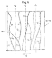
- a minimum amount of the material is distributed on the bottom of the grids 11A, 11B next to the curved baffles 12, as shown in particular in the schematic magnification of Fig. 6.
- the material unloaded from the auxiliary hopper 31 into the loading grid 11A or 11B is accumulated next to the baffles of the grid and is schematically indicated by references V1, V2, V3, V4.
- the amount of material is minimal with respect to the total loading volume of the grids 11A, 11B and is distributed next to the baffles 12 forming the grids 11A, 11B by effect of the movement of said grid.
- a sort of veining whose pattern is defined by the curved baffles 12 of the grid, is formed.
- line F1 represents the relative position in a temporal instant and that this position changes slightly in time due to the movement of the trolley and the grid 11A, 11B before closing the feeding slit. This movement will not be considered in the description that follows for the sake of simplicity.
- the powder unloaded from auxiliary hopper 31 in position F1 is accumulated against the first curved baffle 12 and forms continuous veining V1.
- the powder unloaded from the auxiliary hopper 31 in position F2 accumulates against the two different curved baffles 12, forming broken veining V2.
- the veining V2 is broken in the point where the line F2 crosses the baffle indicated by reference 12A.
- the powder unloaded from position F3 forms veining V3, subdivided into two parts, and the powder unloaded from position F4 forms broken veining V4.
- a veining distribution sequence with consequent changes in the pattern on the tiles can be obtained by suitably controlling the movement of the distributing valve 41 according to the position of the grid 11A or 11B underneath.
- the valves can open in variable positions of the grid 11A or 11B at each passage of the trolley 3 under the auxiliary hoppers, with the consequent creation of random patterns.
- the opening time of each valve, the number of times that the valve opens and the direction of opening (with consequent unloading from either one or the other of the compartments 1A, 31B) can be controlled to increase the number of patterns reproduced on the various tiles.
- the number of patterns which can be obtained can be additionally increased by using different powders in the four compartments 31A, 31B of the two auxiliary hoppers 31 to manufacture tiles whose veining is distributed in an essentially random fashion.
- the movement of the distributing valve 41 forces the powder material contained in the volume defined by the aperture 41A or 41B of the valve. Consequently, a very limited opening time of the valve is required to feed the required amount of powder material. This can be exploited to suitably program the distribution of veining V1-V4 in the grid 11A, 11B. Furthermore, the opening and closing system can be exploited to obtain a very accurate control of the starting and end instant of powder feeding from the hoppers 31, with consequent excellent control over the distribution of veining.
- the auxiliary hopper 31 is definitively closed with a movement of the distributing valve 41 when the loading grids 11A, 11B are passed underneath, essentially before the auxiliary grids 13A, 13B pass to prevent feeding powder material contained in the compartments 31A, 31B into the auxiliary hopper 31. This is because the presence of these powders in the auxiliary grids 13A, 13B is unnecessary.
- the movement of the trolley ends when the grids 11A, 11B and 13A, 13B are under the main hopper 17 or slightly by the side, as shown in Fig. 5E.
- the hopper 17 is opened when the grids 11A, 11B, 13A, 13B pass underneath so to feed the powder and fill the grids entirely. Filling is obtained by the movement of the trolley 3 under the hopper 17.
- each of the grids 11A, 11B contain a mass of basic material from the main hopper 17 and a number of small veins V1-V4 of colored material from the respective auxiliary hopper 31. This veining of material remains essentially in the same position, i.e. next to the baffles 12 of the grids 11A, 11B (as shown in Fig. 6) during the following travel of the trolley 3 towards the press 5, due to the presence of the material fed by the hopper 17 on top.
- the colored powders fed by the auxiliary hoppers 31 form veining which remains visible on the surface of the tile.
- the veining can be enhanced by slightly polishing the visible surface of the tile after pressing, either before or after firing.
- the resulting product in essence, is a ceramic tile comprising a main thickness made of basic material (whose color can be uniform or variable in the tile and from tile to tile) with veining of a different color with respect to that of the basic material on the visible surface of the tile formed by the random distribution of coloring powders, said veining concerning a fraction of the thickness of the tile.
- An effect of the random distribution of the decoration - also if less valuable - can be obtained by using an auxiliary hopper which is not subdivided into two portions, but feeds a single type of coloring powder.
- the number of coloring powders which can be used can be increased by using more than one auxiliary hopper arranged in series.
- two auxiliary hoppers can be arranged in series, each split into two internal compartments and equipped with a distributing valve with two feeding apertures. In this way, four different types of coloring powders can be fed in different ways.
- the illustrated device can be advantageously controlled by a central programmable control unit, e.g. a programmable logic controller (PLC) or a microprocessor.
- the control unit manages the movement of the trolley 3, the opening and closing of the main hopper 17 (which is advantageously provided with a lower closing unit 16), the movement of the distributing valves 41, the operation of the distribution units 20A-20C or other means of distribution of the powders to the main hopper 17, and all other required movements.
- PLC programmable logic controller
Abstract
Description
- The invention relates to a press loading device for manufacturing ceramic tiles.
- The invention also relates to a press equipped with a loading device as well as a method for loading a press for manufacturing ceramic tiles.
- The need for making finished products with particular aesthetic effects is increasingly felt in the ceramic tile manufacturing sector. Specifically, effects which reproduce the appearance of natural stone are sough in the pressing of porcelain stoneware. For this purpose, powdered materials of various colors are mixed in a particular fashion to obtain decorations which are as similar as possible to the natural appearance of stone, avoiding the creation of repeated patterns.
- Italian patent nr. 1,280,079 describes a loading device of the type comprising a trolley with reciprocating movement for taking powder from a main feeding hopper and for transferring the powders to at least one press die-matrix; and wherein the trolley has at least one loading grid, which is filled with powders to transfer the powders to the die-matrix or die-matrixes of the press.
- In the case of this type of known trolley, special decorative effects are obtained by a powder mixing device arranged in the hopper intended to feeding a layer of decorative powdered material into the die loading or filling grids.
- Italian patent nr. 1,287,772 describes a device for feeding powders or sand into a press die-matrix loading grid for manufacturing tiles. In this device, various powders are unloaded in a controlled fashion by a set of hoppers onto a slanted chute. From here, the powders fall into an elongated hopper which develops transversely with respect to the direction of movement of the press die-matrix loading grid. From the hopper, the powders are unloaded into the underlying grid at each loading cycle. Special decorative effects on the finished tile are obtained by overlaying several layers of various colored powders on the slanted chute and unloading them from the feeding hopper to the loading grid.
- European patent nr. 605930 describes a method and device for loading powders into die-matrixes for the production of tiles. The device consists of a powder feeding system from a plurality of overhead containers via a plurality of tubes. Veining of powder of various colors is formed in a distributor which feeds the lower grid, which can be formed by variously shaped baffles, whose shape may be irregular.
- Object of the invention is to realize a loading device for manufacturing ceramic tiles with veining similar to that of stone, that is randomly distributed, as characteristically occurs in natural materials.
- In order to obtain tiles with thin veining arranged in a random fashion on the visible surface of the tile, the invention provides a loading device which is capable of depositing small amounts of suitably coloring powders (atomized, micronized or other) in the die-matrix loading grid of the press during the return phase of the grid from the press.
- Essentially, the device according to the invention comprises an auxiliary hopper arranged downstream to the main feeding hopper - with respect to the direction of advancement of the trolley from the loading area to the die-matrix - and developing transversally with respect to the direction of advancement of the trolley. The auxiliary hopper is equipped with a distributor for distributing a controlled amount of at least one coloring powder into the loading grid during the return travel of the grid from die to the main feeding hopper.
- Additional features and embodiments of the device according to the invention are set forth in the annexed dependent claims.
- The invention also relates to a method for manufacturing ceramic tiles comprising the following phases:
- loading ceramic powders into a loading grid in a feeding station;
- transferring said loading grid to a press;
- loading the powders into at least one die-matrix of said press;
- returning the loading grid into said feeding station to fill it with powder again.
- a metered amount of at least one coloring powder is distributed into said loading grid along the return travel from the press to the feeding station; and
- said metered amount of at least one coloring powder forms one or more veins in the tile by effect of the movement of said loading grid.
- Additional advantageous features and embodiments of the method according to the invention are set forth in the annexed dependent claims.
- The invention will now be better understood by the way of the following description and the accompanying drawing which shows a practical nonlimiting embodiment of the invention. In the drawing:
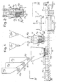
- Fig. 1 is a lateral, partial, cross-sectional view according to a vertical plane of the loading device according to the invention;
- Fig. 2 is a detail of the auxiliary hopper;
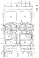
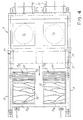
- Fig. 3 and 4 are cross-sectional views according to III-III and IV-IV in Fig. 1;
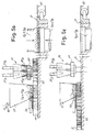
- Figs 5A to 5E schematically show various phases of the die-matrix loading process by means of the device according to the invention; and
- Fig. 6 is a schematic plan view of one of the main loading grids in an intermediate filling phase.
-
- With initial reference to Figs. 1 to 4, the loading device, generically indicated by
reference numeral 1, comprises atrolley 3 reciprocatingly mobile in the direction of the double arrow f3 from a loading position, illustrated in Fig. 1, where the powders are loaded onto the trolley, to a filling position of one or more die-matrixes of a press, generically indicated byreference numeral 5. In the example shown, thepress 5 presents a double die. Each die is equipped with a lower punch (indicated byreferences references 9A and 9B). References f7 and f9 indicate the upwards and downwards movements of the lower punch and the upper punch, respectively. - As appears specifically in Fig. 3 and 4, the
trolley 3 presents a number of loading grids, indicated with 11A and 11B, equal to the number of dies - and consequently to the number of matrixes of the press 5 - to be filled. The plan dimension of eachloading grid reference numeral 12, whose shape is irregular and generally curved. - Two corresponding auxiliary grids, indicated by
references loading grid press 5, for the purposes described below. Thegrids straight baffles 14, whose development is orthogonal to the direction of movement (arrow f3) of thetrolley 3. - In the example shown a main feeding hopper, indicated by
reference numeral 17, is arranged in the loading station, where thetrolley 3 is found in the arrangement shown in Fig. 1. Themain feeding hopper 17 is developed in the orthogonal direction with respect to the direction f3 of movement of thetrolley 3 and is subdivided into two parts to feed powders to the twogrid pairs chute 18 is arranged over themain feeding hopper 17, onto which powder from one or moreoverhead containers rotary valve 20A, 20B, 20C or other suitably controlled metering means. In this way, by operating either one or the other of themeans 20A, 20B, 20C, different powders can be unloaded onto thechute 18 and consequently into themain feeding hopper 17. The feeding system briefly described is similar to that illustrated in the mentioned Italian patent nr. 1,287,772, to which reference is made. However, it should be understood that different methods for filling thegrids press 5 may be employed. in general, any method for distributing powders into the grids may be adopted. - A respective auxiliary hopper, generically indicated by
reference 31, is arranged downstream with respect to themain hopper 17 between the main hopper and thepress 5 for each pair ofgrids respective grid - Each
hopper 31 is subdivided by a longitudinalintermediate partition 32 into twocompartments - Two distributors 35A, 35B - which receive powders via
conduits overhead containers compartments auxiliary hoppers 31. The distributors 35A, 35B have elongated unloading apertures according to the longitudinal development of theauxiliary hoppers 31 so to distribute the powders along the entire longitudinal development of thecompartments hoppers 31. The fourcontainers hoppers 31 each receive the same two types of powders in the twocompartments - It is understood that the
auxiliary hoppers hoppers main hopper 17. - The lower unloading mouth of each
auxiliary hopper 31 is closed by a respective distributingvalve 41 with twounloading apertures apertures auxiliary hopper 31, or be subdivided into slots whose length is shorter than the total longitudinal development of theauxiliary hopper 31. - Two cylinder-piston actuators or other type, indicated by
references auxiliary hopper 31 to control the movement of the distributingvalve 41 according to the double arrow f41. In this way, the distributingvalve 41 may assume one of the three positions shown in Figs. 1, 2 and 5D, respectively. In Fig. 1, the distributingvalve 41 is in a position that closes the unloading mouth of the respectiveauxiliary hopper 31. This is because theapertures compartments auxiliary hopper 31 is subdivided and over alower closing plate 45. Theapertures plate 45. - In Fig. 2, the distributing
valve 41 is moved to the right with respect to the intermediate position assumed in Fig. 1. In this way, theinner compartment 31B of theauxiliary hopper 31 can unload a small amount of powder material through theaperture 41B in the distributingvalve 41 downwards. In the arrangement shown in Fig. 5D, on the other hand, the distributingvalve 41 is moved leftwards and puts theinner compartment 31A of the respectiveauxiliary hopper 31 into connection with the outside to unload the material therein contained. - Because the two cylinder-
piston actuators valve 41 can be moved and arranged on a slant, also only of a few degrees, with respect to the middle plane of the respectiveauxiliary hopper 31. In this way, the width of the material unloading aperture may be varied along the longitudinal development of thehopper 31, to unload a variable amount of material from one end of the hopper to anotherhopper 31, for the purposes which will be illustrated in detail below. Furthermore, thevalves 41 of the twoauxiliary hoppers 31 can be controlled independently one respect to the other. - Furthermore, each
auxiliary hopper 31 is equipped withscrapers 47 that prevent the accidental, undesired output of material and the reciprocal mixing of powder in the twointernal compartments - The operation of the loading device described to this point is clearly illustrated in Figs 5A-5E.
- In a previous phase with respect to that shown in Fig. 5A, the
loading grids auxiliary grids main hopper 17 and - for themain grids auxiliary hoppers 31, as described below. - In Fig. 5A, the
loading grids lower punch press 5. The lower punch is in line with a sliding surface P which extends from the trolley loading area to the press dies and from there to aconveyor belt 51 for removing the manufactured tiles. Thus, in the arrangement shown in Fig. 5A, the powders contained in theloading grids auxiliary grids trolley 3 into thepress 5, the front part of thetrolley 3 has pushed the tile P1 formed during the previous cycle from the pressing area onto aconveyor belt 51 which carries it to the oven. - Once the
trolley 3 has reached the position in Fig. 5A, thelower punches loading grids punches auxiliary grids auxiliary grids - The height of the
loading grids press 5 whereby entirely emptying theloading grids auxiliary grids loading trolley 3, as shown in Fig. 5C. - The
auxiliary grids press 5. In other words, the total of the powder material in each pair ofgrids - Continuing the return movement, the
trolley 3 passes under the auxiliary hoppers 31 (Fig. 5D). Eachhopper 31 is opened, by a controlled movement in either one and/or the other direction of the distributingvalve 41, to unload a small amount of powder material from one of the two compartments (or in sequence from both compartments) 31A, 31B of eachauxiliary hopper 31 into the space defined by thebaffles 12 of therespective loading grid grids curved baffles 12, as shown in particular in the schematic magnification of Fig. 6. - In this figure, the material unloaded from the
auxiliary hopper 31 into theloading grid grids baffles 12 forming thegrids curved baffles 12 of the grid, is formed. - The distribution of the veining V1-V4 of the material fed by the
auxiliary hoppers 31 into thegrids baffles 12 and the temporal sequence in which the respective distributingvalve 41 is opened. This effect is clearly illustrated in Fig.6. In this figure, horizontal dotted lines (indicated by references F1-F4), which are orthogonal to the direction f3 of movement of thetrolley 3 carrying thegrids valve 41. In other terms, for example, line F1 indicates the position in which thegrid valve 41. It is understood that the line F1 represents the relative position in a temporal instant and that this position changes slightly in time due to the movement of the trolley and thegrid - The powder unloaded from
auxiliary hopper 31 in position F1 is accumulated against the firstcurved baffle 12 and forms continuous veining V1. The powder unloaded from theauxiliary hopper 31 in position F2 accumulates against the two differentcurved baffles 12, forming broken veining V2. The veining V2 is broken in the point where the line F2 crosses the baffle indicated byreference 12A. Similarly, the powder unloaded from position F3 forms veining V3, subdivided into two parts, and the powder unloaded from position F4 forms broken veining V4. - A veining distribution sequence with consequent changes in the pattern on the tiles can be obtained by suitably controlling the movement of the distributing
valve 41 according to the position of thegrid grid trolley 3 under the auxiliary hoppers, with the consequent creation of random patterns. The opening time of each valve, the number of times that the valve opens and the direction of opening (with consequent unloading from either one or the other of thecompartments 1A, 31B) can be controlled to increase the number of patterns reproduced on the various tiles. The number of patterns which can be obtained can be additionally increased by using different powders in the fourcompartments auxiliary hoppers 31 to manufacture tiles whose veining is distributed in an essentially random fashion. - As clearly appears in Fig. 2, the movement of the distributing
valve 41 forces the powder material contained in the volume defined by theaperture grid hoppers 31, with consequent excellent control over the distribution of veining. - The
auxiliary hopper 31 is definitively closed with a movement of the distributingvalve 41 when theloading grids auxiliary grids compartments auxiliary hopper 31. This is because the presence of these powders in theauxiliary grids - The movement of the trolley ends when the
grids main hopper 17 or slightly by the side, as shown in Fig. 5E. Thehopper 17 is opened when thegrids trolley 3 under thehopper 17. - After filling, each of the
grids main hopper 17 and a number of small veins V1-V4 of colored material from the respectiveauxiliary hopper 31. This veining of material remains essentially in the same position, i.e. next to thebaffles 12 of thegrids trolley 3 towards thepress 5, due to the presence of the material fed by thehopper 17 on top. - In this way, the colored powders fed by the
auxiliary hoppers 31 form veining which remains visible on the surface of the tile. The veining can be enhanced by slightly polishing the visible surface of the tile after pressing, either before or after firing. - The resulting product, in essence, is a ceramic tile comprising a main thickness made of basic material (whose color can be uniform or variable in the tile and from tile to tile) with veining of a different color with respect to that of the basic material on the visible surface of the tile formed by the random distribution of coloring powders, said veining concerning a fraction of the thickness of the tile.
- An effect of the random distribution of the decoration - also if less valuable - can be obtained by using an auxiliary hopper which is not subdivided into two portions, but feeds a single type of coloring powder.
- The number of coloring powders which can be used can be increased by using more than one auxiliary hopper arranged in series. For example, two auxiliary hoppers can be arranged in series, each split into two internal compartments and equipped with a distributing valve with two feeding apertures. In this way, four different types of coloring powders can be fed in different ways.
- The illustrated device can be advantageously controlled by a central programmable control unit, e.g. a programmable logic controller (PLC) or a microprocessor. The control unit manages the movement of the
trolley 3, the opening and closing of the main hopper 17 (which is advantageously provided with a lower closing unit 16), the movement of the distributingvalves 41, the operation of the distribution units 20A-20C or other means of distribution of the powders to themain hopper 17, and all other required movements. - It is understood that the drawing only shows a possible embodiment of the invention, which may be varied in its forms and dispositions without however departing from the scope of the underlying concept of the invention.
Claims (19)
- A press loading device for manufacturing ceramic tiles, comprising a trolley with an alternate movement for taking powders from a main feeding hopper and transferring the powders to at least one die-matrix of said press, said trolley presenting at least one loading grid which is filled with said powders and which transfers said powders to said at least one matrix, characterized in that it comprises at least one auxiliary hopper arranged downstream to the main feeding hopper with reference to the direction of movement of the trolley towards said die and developing transversally to the direction of advancement of the trolley, said auxiliary hopper being equipped with a distributor member to distribute a controlled amount of at least one coloring powder onto the bottom of the loading grid during the return travel of the loading grid from the die to the main feeding hopper.
- Device according to claim 1, characterized in that said trolley comprises an auxiliary grid, arranged in series and preferably in front of the loading grid with respect to the direction of advancement to the press die, said auxiliary grid being filled with the powders distributed by said main feeding hopper.
- Device according to claim 2, characterized in that said auxiliary grid ensures the complete filling of said at least one die, while the loading grid is completely emptied after each cycle by unloading the content into said at least one die.
- Device according to claim 1, 2 or 3, characterized in that said distributor member comprises at least one distributing valve with at least a feeding aperture which opens and closes the unloading mouth of the auxiliary hopper.
- Device according to claim 4, characterized in that said at least one distributing valve feeding aperture essentially extends along the entire longitudinal development of the auxiliary hopper unloading mouth.
- Device according to claim 4 or 5, characterized in that said distributing valve is equipped with two feeding apertures which are essentially parallel and arranged side by side in the direction of movement of said trolley and in that the auxiliary hopper is subdivided longitudinally into two compartments, each of which can unload its contents into the loading grid via one of said apertures in the distributing valve.
- Device according to claim 4, 5 or 6, characterized in that said distributing valve can be slanted with respect to the unloading mouth of the auxiliary hopper, to feed a variable amount of powder along the longitudinal development of the unloading mouth of the auxiliary hopper into said loading grid.
- Device according to one or more of the claims from 4 to 7, characterized in that the movement of said distributing valve is controlled by at least one actuator controlled by a programmable control unit to change the position of the distributing valve according to the position of the loading grid with respect to the auxiliary hopper.
- Device according to one or more of the claims from 4 to 8, characterized in that the movement of said distributing valve is controlled by a pair of actuators arranged on the ends of the valve.
- Device according to one or more of the preceding claims, characterized in that said loading grid consists of curved baffles.
- Press for manufacturing ceramic tiles comprising at least one die and one device for loading powder material in the die-matrix, characterized in that said loading device is made according to one or more of the claims 1 to 10.
- Method for manufacturing pressed ceramic tiles, comprising the following phases:characterized in that:loading ceramic powders into a loading grid in a feeding station;transferring said loading grid to a press;unloading the powders into at least one die-matrix of said press;returning the loading grid into said feeding station to fill the loading grid with powders again;a metered amount of at least one coloring powder is distributed into said loading grid along the return travel of the trolley from the press to the feeding station; andsaid metered amount of at least one coloring powder forms one or more veins in said loading grid, which will create a pattern of superficial veins in the tile.
- Method according to claim 12, characterized in that the loading grid is completely emptied by unloading the powder material therein contained into the respective die-matrix each time it is inserted in the press.
- Method according to claim 13, characterized in that die-matrix filling is completed by an auxiliary amount of powders contained in an auxiliary grid arranged in series to the loading grid with respect to its direction of movement.
- Method according to one or more of the claims 12 to 14, characterized in that said metered amount of at least one coloring powder is distributed in a variable fashion along a direction which is parallel to the movement of the loading grid.
- Method according to one or more of the claims 12 to 15, characterized in that said metered amount of coloring powder is distributed in a variable fashion in a direction which is orthogonal to the movement of the loading grid.
- Method according to one or more of the claims 12 to 16, characterized in that the distribution of said coloring powder is controlled as a function of the position of the loading grid.
- Method according to one or more of the claims 12 to 17, characterized in that two different coloring powders are distributed in said loading grid.
- A ceramic tile comprising a main thickness made of basic material with veining of a different color with respect to that of the basic material on the visible surface of the tile formed by the random distribution of coloring powder, said veining concerning a fraction of the thickness of the tile.
Applications Claiming Priority (2)
| Application Number | Priority Date | Filing Date | Title |
|---|---|---|---|
| ITFI20010236 | 2001-12-14 | ||
| IT2001FI000236A ITFI20010236A1 (en) | 2001-12-14 | 2001-12-14 | DEVICE FOR LOADING A PRESS FOR THE PRODUCTION OF CERAMIC TILES, A PRESS INCLUDING THE DEVICE AND ITS METHOD |
Publications (2)
| Publication Number | Publication Date |
|---|---|
| EP1319486A2 true EP1319486A2 (en) | 2003-06-18 |
| EP1319486A3 EP1319486A3 (en) | 2004-05-19 |
Family
ID=11442303
Family Applications (1)
| Application Number | Title | Priority Date | Filing Date |
|---|---|---|---|
| EP02425766A Withdrawn EP1319486A3 (en) | 2001-12-14 | 2002-12-12 | Press loading device for manufacturing ceramic tiles, press comprising said device and respective loading method |
Country Status (2)
| Country | Link |
|---|---|
| EP (1) | EP1319486A3 (en) |
| IT (1) | ITFI20010236A1 (en) |
Cited By (14)
| Publication number | Priority date | Publication date | Assignee | Title |
|---|---|---|---|---|
| CN101077591A (en) * | 2006-05-25 | 2007-11-28 | 广东宏陶陶瓷有限公司 | Emulating natural porcelain brick machine-shaping material-distributing equipment and method |
| CN100463788C (en) * | 2005-11-03 | 2009-02-25 | 唐君 | Material distribution method of marbling imitated ceramic brick and material distribution equipment |
| CN101200097B (en) * | 2007-12-24 | 2010-07-21 | 广东科达机电股份有限公司 | Tumbling and splashing medallion burden distribution device |
| CN101786290A (en) * | 2010-02-11 | 2010-07-28 | 佛山市点石机械有限公司 | Material distributing method and system for forming emperador pattern on polished tile |
| CN102092093A (en) * | 2010-11-19 | 2011-06-15 | 梁海果 | Deforming grid device for ceramic brick production |
| CN102248595A (en) * | 2011-07-16 | 2011-11-23 | 广东东鹏陶瓷股份有限公司 | Material distributing method and equipment of polished tiles |
| CN104742536A (en) * | 2015-04-16 | 2015-07-01 | 佛山市简一陶瓷有限公司 | Multi-workstation-conveying tile printing device |
| CN106945162A (en) * | 2017-04-13 | 2017-07-14 | 佛山市三水区广顺自动化设备有限公司 | A kind of proportioner |
| CN108247913A (en) * | 2018-01-17 | 2018-07-06 | 福建省东浦科技实业有限公司 | A kind of polychrome apparatus for distributing |
| CN108501184A (en) * | 2018-05-28 | 2018-09-07 | 洛阳震动机械有限公司 | A kind of carbon crucible vibrating forming machine |
| CN108544646A (en) * | 2018-05-04 | 2018-09-18 | 佛山市赛普飞特机械有限公司 | A kind of Ceramic Tiles flat plate decorating machine |
| CN110103319A (en) * | 2019-05-31 | 2019-08-09 | 广东萨米特陶瓷有限公司 | A kind of ceramic sheet and its manufacturing method of the texture containing green body |
| CN113183302A (en) * | 2021-04-20 | 2021-07-30 | 浙江舜虞达环境科技集团有限公司 | Embedded filling composite device of wallboard part filling module |
| CN113478613A (en) * | 2021-07-30 | 2021-10-08 | 中国建筑一局(集团)有限公司 | Construction waste treatment equipment |
Families Citing this family (2)
| Publication number | Priority date | Publication date | Assignee | Title |
|---|---|---|---|---|
| CN110027102A (en) * | 2019-05-19 | 2019-07-19 | 山东易码智能科技股份有限公司 | A kind of cement material distributing machine of view-based access control model |
| CN113650149A (en) * | 2021-07-15 | 2021-11-16 | 浙江宏锦再生资源有限公司 | Full-automatic closed building block production system |
Citations (3)
| Publication number | Priority date | Publication date | Assignee | Title |
|---|---|---|---|---|
| DE1281915B (en) * | 1965-03-27 | 1968-10-31 | Thuringia Feinkeramikmaschinen | Filling device on presses for manufacturing two-layer panels |
| NL6707021A (en) * | 1967-05-22 | 1968-11-25 | Mosa Porselein & Tegelfab | METHOD AND INSTALLATION FOR PRESSING MULTILAYER TILES |
| EP0873832A1 (en) * | 1997-04-23 | 1998-10-28 | SACMI COOPERATIVA MECCANICI IMOLA S.c.r.l. | Apparatus for pressing two-layer ceramic tiles |
-
2001
- 2001-12-14 IT IT2001FI000236A patent/ITFI20010236A1/en unknown
-
2002
- 2002-12-12 EP EP02425766A patent/EP1319486A3/en not_active Withdrawn
Patent Citations (3)
| Publication number | Priority date | Publication date | Assignee | Title |
|---|---|---|---|---|
| DE1281915B (en) * | 1965-03-27 | 1968-10-31 | Thuringia Feinkeramikmaschinen | Filling device on presses for manufacturing two-layer panels |
| NL6707021A (en) * | 1967-05-22 | 1968-11-25 | Mosa Porselein & Tegelfab | METHOD AND INSTALLATION FOR PRESSING MULTILAYER TILES |
| EP0873832A1 (en) * | 1997-04-23 | 1998-10-28 | SACMI COOPERATIVA MECCANICI IMOLA S.c.r.l. | Apparatus for pressing two-layer ceramic tiles |
Cited By (18)
| Publication number | Priority date | Publication date | Assignee | Title |
|---|---|---|---|---|
| CN100463788C (en) * | 2005-11-03 | 2009-02-25 | 唐君 | Material distribution method of marbling imitated ceramic brick and material distribution equipment |
| CN101077591A (en) * | 2006-05-25 | 2007-11-28 | 广东宏陶陶瓷有限公司 | Emulating natural porcelain brick machine-shaping material-distributing equipment and method |
| CN101200097B (en) * | 2007-12-24 | 2010-07-21 | 广东科达机电股份有限公司 | Tumbling and splashing medallion burden distribution device |
| CN101786290A (en) * | 2010-02-11 | 2010-07-28 | 佛山市点石机械有限公司 | Material distributing method and system for forming emperador pattern on polished tile |
| CN101786290B (en) * | 2010-02-11 | 2013-07-10 | 佛山市点石机械有限公司 | Material distributing method for forming emperador pattern on polished tile |
| CN102092093A (en) * | 2010-11-19 | 2011-06-15 | 梁海果 | Deforming grid device for ceramic brick production |
| CN102248595A (en) * | 2011-07-16 | 2011-11-23 | 广东东鹏陶瓷股份有限公司 | Material distributing method and equipment of polished tiles |
| CN104742536A (en) * | 2015-04-16 | 2015-07-01 | 佛山市简一陶瓷有限公司 | Multi-workstation-conveying tile printing device |
| CN106945162A (en) * | 2017-04-13 | 2017-07-14 | 佛山市三水区广顺自动化设备有限公司 | A kind of proportioner |
| CN108247913A (en) * | 2018-01-17 | 2018-07-06 | 福建省东浦科技实业有限公司 | A kind of polychrome apparatus for distributing |
| CN108247913B (en) * | 2018-01-17 | 2024-03-15 | 福建省东浦科技实业有限公司 | Multicolor cloth equipment |
| CN108544646A (en) * | 2018-05-04 | 2018-09-18 | 佛山市赛普飞特机械有限公司 | A kind of Ceramic Tiles flat plate decorating machine |
| CN108501184A (en) * | 2018-05-28 | 2018-09-07 | 洛阳震动机械有限公司 | A kind of carbon crucible vibrating forming machine |
| CN108501184B (en) * | 2018-05-28 | 2024-01-23 | 洛阳震动机械有限公司 | Carbon crucible vibration forming machine |
| CN110103319A (en) * | 2019-05-31 | 2019-08-09 | 广东萨米特陶瓷有限公司 | A kind of ceramic sheet and its manufacturing method of the texture containing green body |
| CN113183302A (en) * | 2021-04-20 | 2021-07-30 | 浙江舜虞达环境科技集团有限公司 | Embedded filling composite device of wallboard part filling module |
| CN113478613A (en) * | 2021-07-30 | 2021-10-08 | 中国建筑一局(集团)有限公司 | Construction waste treatment equipment |
| CN113478613B (en) * | 2021-07-30 | 2022-05-17 | 中国建筑一局(集团)有限公司 | Construction waste treatment equipment |
Also Published As
| Publication number | Publication date |
|---|---|
| ITFI20010236A1 (en) | 2003-06-16 |
| EP1319486A3 (en) | 2004-05-19 |
Similar Documents
| Publication | Publication Date | Title |
|---|---|---|
| EP1319486A2 (en) | Press loading device for manufacturing ceramic tiles, press comprising said device and respective loading method | |
| MXPA06007668A (en) | Method and plant for prearranging powders for forming ceramic tiles or slabs. | |
| CA2301703C (en) | Method for producing concrete stones, especially paving stones, building stones or such like | |
| EP0605930A1 (en) | Method for the manufacture of dry-moulded tiles, with relative moulding plant and tile | |
| EP0693352B1 (en) | Device for feeding the mould loading carriage in ceramic tile manufacture | |
| EP3894155B1 (en) | Machine for dry decoration of tiles | |
| EP0744340B1 (en) | Product dispensing apparatus and method | |
| EP0822044A1 (en) | Loading system for the moulds of ceramic presses for forming pressure-glazed tiles, and relative implementation means | |
| EP0941826A2 (en) | Method for manufacturing a decorated tile, the relative loading device for the press moulds, and a tile manufactured thereby | |
| EP0444730B1 (en) | Double-loading carriage for ceramic moulds in general, and typically for the manufacture of pressure-glazed tiles | |
| EP0492733B1 (en) | Device and method of manufacturing ceramic tiles | |
| EP0909622B1 (en) | Device and method for feeding the mould cavity with powder or granular material, in ceramic tile manufacture | |
| US3720738A (en) | Method for producing compression-molded articles | |
| WO2005025829B1 (en) | Method and plant for forming ceramic tiles or slabs | |
| EP0940235A2 (en) | Machine for the production of tiles with variation of colour in the body | |
| EP1773553B1 (en) | Plant for feeding a double layer of powder or granular material into the cavity of the mould for ceramic tile production | |
| EP0839618B1 (en) | Clay loading device for ceramic tile presses | |
| CN113165206B (en) | Method for decorating ceramic plates in thickness | |
| EP0922549B1 (en) | Method and device for loading ceramic press moulds | |
| EP0962294A2 (en) | Device for feeding powders to a ceramic tile forming press | |
| JPH0911222A (en) | Method and apparatus for producing patterned concrete block | |
| JP2689963B2 (en) | Method for molding concrete block having laminated cross section | |
| EP2069120B1 (en) | Distributor means, apparatus and method for producing a decorated ceramic product | |
| CN115476429A (en) | Method and apparatus for manufacturing ceramic products | |
| EP1048426A2 (en) | An apparatus for distributing batched quantities of powder or granular materials on surfaces |
Legal Events
| Date | Code | Title | Description |
|---|---|---|---|
| PUAI | Public reference made under article 153(3) epc to a published international application that has entered the european phase |
Free format text: ORIGINAL CODE: 0009012 |
|
| AK | Designated contracting states |
Designated state(s): AT BE BG CH CY CZ DE DK EE ES FI FR GB GR IE IT LI LU MC NL PT SE SI SK TR |
|
| AX | Request for extension of the european patent |
Extension state: AL LT LV MK RO |
|
| PUAL | Search report despatched |
Free format text: ORIGINAL CODE: 0009013 |
|
| AK | Designated contracting states |
Kind code of ref document: A3 Designated state(s): AT BE BG CH CY CZ DE DK EE ES FI FR GB GR IE IT LI LU MC NL PT SE SI SK TR |
|
| AX | Request for extension of the european patent |
Extension state: AL LT LV MK RO |
|
| RIC1 | Information provided on ipc code assigned before grant |
Ipc: 7B 28B 1/00 B Ipc: 7B 28B 17/00 B Ipc: 7B 28B 13/02 A |
|
| 17P | Request for examination filed |
Effective date: 20040528 |
|
| AKX | Designation fees paid |
Designated state(s): AT BE BG CH CY CZ DE DK EE ES FI FR GB GR IE IT LI LU MC NL PT SE SI SK TR |
|
| 17Q | First examination report despatched |
Effective date: 20090518 |
|
| STAA | Information on the status of an ep patent application or granted ep patent |
Free format text: STATUS: THE APPLICATION IS DEEMED TO BE WITHDRAWN |
|
| 18D | Application deemed to be withdrawn |
Effective date: 20090929 |