EP0822044A1 - Loading system for the moulds of ceramic presses for forming pressure-glazed tiles, and relative implementation means - Google Patents
Loading system for the moulds of ceramic presses for forming pressure-glazed tiles, and relative implementation means Download PDFInfo
- Publication number
- EP0822044A1 EP0822044A1 EP97202274A EP97202274A EP0822044A1 EP 0822044 A1 EP0822044 A1 EP 0822044A1 EP 97202274 A EP97202274 A EP 97202274A EP 97202274 A EP97202274 A EP 97202274A EP 0822044 A1 EP0822044 A1 EP 0822044A1
- Authority
- EP
- European Patent Office
- Prior art keywords
- belt
- layer
- plant
- cavity
- tile
- Prior art date
- Legal status (The legal status is an assumption and is not a legal conclusion. Google has not performed a legal analysis and makes no representation as to the accuracy of the status listed.)
- Granted
Links
Images


Classifications
-
- B—PERFORMING OPERATIONS; TRANSPORTING
- B28—WORKING CEMENT, CLAY, OR STONE
- B28B—SHAPING CLAY OR OTHER CERAMIC COMPOSITIONS; SHAPING SLAG; SHAPING MIXTURES CONTAINING CEMENTITIOUS MATERIAL, e.g. PLASTER
- B28B13/00—Feeding the unshaped material to moulds or apparatus for producing shaped articles; Discharging shaped articles from such moulds or apparatus
- B28B13/02—Feeding the unshaped material to moulds or apparatus for producing shaped articles
- B28B13/0215—Feeding the moulding material in measured quantities from a container or silo
- B28B13/022—Feeding several successive layers, optionally of different materials
-
- B—PERFORMING OPERATIONS; TRANSPORTING
- B28—WORKING CEMENT, CLAY, OR STONE
- B28B—SHAPING CLAY OR OTHER CERAMIC COMPOSITIONS; SHAPING SLAG; SHAPING MIXTURES CONTAINING CEMENTITIOUS MATERIAL, e.g. PLASTER
- B28B13/00—Feeding the unshaped material to moulds or apparatus for producing shaped articles; Discharging shaped articles from such moulds or apparatus
- B28B13/02—Feeding the unshaped material to moulds or apparatus for producing shaped articles
- B28B13/0215—Feeding the moulding material in measured quantities from a container or silo
- B28B13/027—Feeding the moulding material in measured quantities from a container or silo by using a removable belt or conveyor transferring the moulding material to the moulding cavities
Definitions
- the translationally shiftable surfaces can further be more than one in number, each carrying one or more layers.
- the tiles are to have a geometrical surface decoration
- at least some of said vessels are provided with means for distributing the material on a suitable support surface, such as a translationally shiftable belt, to be called the collection belt, via means arranged to intercept the falling material flow, to shape it in accordance with the desired pattern.
- the collection belt which is conveniently supported by a loading device positioned in front of the ceramic mould, can be made to advance towards this latter until the front generating line of its upper portion comes into vertical alignment with the edge of that forming cavity situated on the opposite side to that where said loading device is located.
- Said third layer has a thickness preferably of between 5 and 20 mm.
- the second intermediate belt is overlaid by a series of loading hoppers each containing a single-colour material.
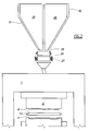
- the collection belt 8 extends between a motorized rear roller 9 and an idle front roller 10, with which there is associated a usual pusher with scraper 333 for discharging the formed tiles and removing excess powder mixture.
- the hopper 18 and the hoppers A1...D1 which are provided with lower closure gates, are as wide as the front of the press and as the underlying belts 17, 19 and 8, are overlaid by a traversing distributor 181, 20, 21, 22, 23 respectively, which receives a flexible feed tube 182, 200, 201, 202, 203 respectively.
- the flexible tube 182 is connected to an overlying silo, not shown.
- the hoppers A1...D1 are movable vertically from a position adjacent to the belt 19, to a raised position.
- the belt 24 is as wide as the underlying belt 8 and carries a succession of decoration screens 241 arranged in lines of three (see Figure 4).
- the collection vessels A, B, C and D are overlaid by a distributor belt 26 passing about two rollers 260 mounted on a frame 27 which can be moved translationally in a horizontal direction to position the end of the belt 26 above one or another of said collection vessels.
- a blade mixer 36 or equivalent driven by a geared motor unit 35, which is operated when desired.
- Each vessel feeds the underlying hopper A1, B1, C1, D1 via the respective flexible tube 200, 201, 202, 203 and the respective reciprocating feeder 20, 21, 22, 23.
- Control means of usual type ensure that a sufficient quantity of material is present in each of said vessels and said hoppers, each of which hence contains a material of different quality.
- the powder layer is made to advance by the belt 8 until, on passing below the end of the belt 19 at the same speed thereas, it receives a convenient layer of background material discharged in the illustrated example by the hopper C1, which at the appropriate moment is closed and raised into its rest position.
- the loading device 4 shown in Figure 1 is formed as shown in Figure 6, in which it consists of a single frame 70 which supports two aligned collection belts 81 and 82 and is connected to the geared motor unit 5 via the connecting rod 6.
- the frames 81 and 82 are moved in opposite directions.
- the hopper 33 causes a certain quantity of powder material to fall through the decoration screens 241, to form a powder pattern on the underlying collection belt 82.
- the pattern so formed is advanced by the belt 82 as far as the front end of the feed belt 19, which advances at the same speed as the belt 82 to deposit on the powder pattern a uniform layer of background material created by one of the hoppers A1....D1 on said belt 19.
- the frame 70 is made to move translationally until positioned as shown in the figure with dashed lines and is then made to withdraw while the belt 82 advances because of the provision of the rack 16 and free-wheel pinion 15, to discharge the two layers (pattern and background) in the mould 2.
- the belt 81 begins to advance, at the withdrawal speed of the frame 70, when its left end is in correspondence with the left end of the mould 2, so as to discharge the base material into the mould.
- the tile is formed inverted, ie with its exposed side facing downwards, however it could evidently be formed the right way up.
- the plant shown in Figure 7 is used, in which the tile base material depositing device, consisting of the elements 17, 18, 180, 181, 182 shown in Figure 1, is positioned upstream of the device which deposits the material forming the tile background.
- the powder is fed to the mould cavity by a usual loading system 50 provided with a loading trolley.
- the trolley 502 is fed by the collection belt 51 which is entirely similar to and and driven in the same manner as the belt 8 of Figure 1.
- the frame 52 is provided upperly with four equidistant flat cross-members of rectangular section which are positioned in correspondence with the space lying between the rows of screens 53 and the frame 52 and the space between two adjacent rows of screens 53.
- the function of the cross-members 54 is to close the lower mouth of three hoppers 55, which move simultaneously and alternately between two adjacent cross-members to feed powder to the underlying screens at each outward or return travel stroke.
- Said hoppers 55 run on two fixed guides 56 connected to the supporting structure of the frame 52, each of them being fed by a traversing flexible tube 57 which, when not feeding the hoppers 55, is positioned on one of the two horizontal plates 58 situated at the ends of each hopper 55.
Abstract
Description
Claims (26)
- A system for loading a multi-component soft mass into the moulds (2) of ceramic tile-forming presses, said moulds comprising at least one forming cavity (3) for tile compaction, characterised by comprising the following operating stages:temporarily placing on a movable horizontal belt (8) at least one layer of powder material,by means of said belt, transferring into said at least one cavity said at least one layer of powder material, without causing it to undergo horizontal displacement.
- A system as claimed in claim 1, characterised in that the transfer is effected by causing the belt (8), while stationary, to overlie the mould cavity, and then withdrawing the belt while simultaneously operating it to rotate it in the opposite direction at the same speed as that at which it is made to withdraw.
- A system as claimed in claim 1, characterised by comprising the following operating stages:temporarily placing at least one layer of a powder material on a further belt (81) coplanar with the belt (8) and supported by the same frame but operable in the opposite direction,by means of said belts, transferring in succession into said at least one cavity, and without their mutual mixing, the layers of powder material placed on the belts.
- A system as claimed in claim 3, characterised in that the transfer is effected by causing the belt (8), while stationary, to overlie the mould cavity and then withdrawing the belt while simultaneously operating it to rotate it in the opposite direction to, and at the same speed as, that at which it is made to withdraw, then operating the further belt (81), when it itself overlies the mould cavity, at the same speed as its withdrawal but in the opposite direction thereto.
- A system as claimed in claim 1, characterised in that at least one first layer and at least one second layer of powder material are placed on the belt (8), one of said layers being intended to form the decoration or exposed face of the tile, the other of said layers being intended to form the body of the tile.
- A system as claimed in the preceding claims, characterised in that the placing of said at least one first and one second layer of powder material and their simultaneous transfer into said cavity are effected by gravity.
- A system as claimed in the preceding claims, characterised in that said at least one first and one second layer are of constant thickness.
- A system as claimed in the preceding claims, characterised in that said at least one first and one second layer have relatively very different thicknesses, the first being of the order of between 0.1 and 5.00 mm and the second between 0.3 and 20 mm.
- A system as claimed in claim 2, characterised in that a third layer of powder material is deposited, said third layer either completely covering the preceding layers or being completely covered thereby.
- A system as claimed in claim 9, characterised in that said third layer has a thickness of between 5.0 and 20 mm.
- A plant for feeding a ceramic tile pressing mould (2) provided with at least one forming cavity (3), characterised by comprising:a loading device (4) movable relative to the mould and provided with at least one horizontal surface (8, 81, 82) which itself is movable relative to the device structure, said surface being arranged to receive a stratified soft mass intended to be compacted to form a tile, or a tile layer,at least one powder material dispensing unit (33) arranged to create at least one layer on said surface,said device (4) being positioned in front of the mould, and being arranged to slide between a first position in which it is distanced from this latter and a second position in which it overlies it, andsaid at least one surface being arranged to slide relative to said device such as to place said soft mass in said cavity without subjecting it to horizontal displacement
- A plant as claimed in claim 11, characterised in that said loading device (4) comprises a horizontal frame (7) which supports said at least one surface (8, 81, 82), and of which the front edge is provided with a pusher with scraper (333) arranged to remove the pressed tiles (14) from the mould and to clean the press surface, said at least one surface consisting of an intermittently operating motorized collection belt.
- A plant as claimed in claim 12, characterised in that said at least one surface comprises at least two coplanar collection belts driven in opposite directions so as to discharge the material layers lying on them through the gap which separates them.
- A plant as claimed in the preceding claims, characterised in that each of said collection belts is driven by a motor unit arranged to cause it to shift translationally, at least during the transfer of said stratified mass into said forming cavity, at a speed which in absolute value is equal to the speed with which the device (4) returns from said second position to said first position.
- A plant as claimed in the preceding claims, characterised by comprising at least one intermediate belt overlying at least one collection belt, and means for distributing said powder material onto said intermediate belt.
- A plant as claimed in the preceding claims, characterised in that the material distributing means are more than one in number, they being positioned in succession overlying the at least one intermediate belt.
- A plant as claimed in the preceding claims, characterised in that a first dispensing unit comprises at least one hopper (33, 55) fed by a device (25, 57) driven to slide relative to the hopper (33, 55), this latter being provided with an exit port positioned above a masking cover (241, 530) which intercepts the flow of falling material, to select it in accordance with a predetermined pattern.
- A plant as claimed in claim 17, characterised in that said masking cover (241) is provided on a belt (24) which lies above said surface (8) and is provided with a longitudinal series of permeable regions of different configurations, and which is caused to shift translationally in order to move the desired permeable regions into their working position.
- A plant as claimed in claim 17, characterised in that said masking cover (530) is supported within the aperture of a flat frame on which the hopper (55) slides.
- A plant as claimed in claim 11, characterised by a second dispensing unit comprising stationary hoppers (A1...D1) fed by overlying devices (20, 21, 22, 23) slidable with reciprocating movement and provided with a closure gate (180), each hopper (20..23) being able to shift in height between a raised rest position and a lowered working position in which it is adjacent to an intermittently operating motorized intermediate belt (19) provided to receive from said stationary hopper said second layer, and to deposit it on the collection belt (8).
- A plant as claimed in claim 20, characterised in that with said device (20...23) there is associated an overlying horizontal feeder belt (26) which is arranged to receive from overlying silos (29...32) respective powder materials directed towards said device, and is able to shift translationally in a horizontal direction.
- A plant as claimed in claim 21, characterised in that between said silos and said feed belt (26) there is interposed a horizontal service belt (28) for the temporary support of materials originating from said silos and directed towards said device (20...23).
- A plant as claimed in claim 22, characterised in that said service belt (28) is provided with an overlying device (35, 36) for mixing the powder materials temporarily deposited thereon.
- A plant for feeding a ceramic tile pressing mould (2) provided with at least one forming cavity (3), characterised by comprising:a loading trolley provided with a loading distributor which can assume a position overlying the mould cavity, and a withdrawn position distant from the mould cavity,a loading device (4) movable relative to said trolley, and provided with at least one horizontal surface (8, 81, 82) which itself is movable relative to the device structure, said surface being arranged to receive a stratified soft mass intended to be compacted to form a tile, or a tile layer,at least one powder material dispensing unit (33) arranged to create at least one layer on said surface,said device (4) being positioned in front of the mould, and being arranged to slide between a first position in which it is distanced from this latter and a second position in which it overlies the distributor of said trolley when this is in its withdrawn position,said at least one surface being arranged to slide relative to said device such as to place said soft mass in said cavity without subjecting it to horizontal displacement.
- A plant as claimed in claim 24, characterised in that said loading device (4) comprises a horizontal frame (7) which supports said at least one surface (8), consisting of an intermittently operating motorized collection belt.
- Pressure-glazed tiles (14) obtained by the system claimed in claims 1 to 10, and by the plant claimed in claims 11 to 25.
Applications Claiming Priority (2)
| Application Number | Priority Date | Filing Date | Title |
|---|---|---|---|
| IT96RE000061A IT1287758B1 (en) | 1996-07-30 | 1996-07-30 | LOADING SYSTEM FOR CERAMIC PRESS MOLDS FOR THE FORMING OF PRESS-GLAZED TILES, AND RELATED IMPLEMENTATION MEANS |
| ITRE960061 | 1996-07-30 |
Publications (2)
| Publication Number | Publication Date |
|---|---|
| EP0822044A1 true EP0822044A1 (en) | 1998-02-04 |
| EP0822044B1 EP0822044B1 (en) | 2002-09-18 |
Family
ID=11398932
Family Applications (1)
| Application Number | Title | Priority Date | Filing Date |
|---|---|---|---|
| EP97202274A Expired - Lifetime EP0822044B1 (en) | 1996-07-30 | 1997-07-21 | Loading system for the moulds of ceramic presses for forming pressure-glazed tiles, and relative implementation means |
Country Status (5)
| Country | Link |
|---|---|
| EP (1) | EP0822044B1 (en) |
| AT (1) | ATE224275T1 (en) |
| DE (1) | DE69715539T2 (en) |
| ES (1) | ES2184026T3 (en) |
| IT (1) | IT1287758B1 (en) |
Cited By (14)
| Publication number | Priority date | Publication date | Assignee | Title |
|---|---|---|---|---|
| WO1998056551A1 (en) * | 1997-06-10 | 1998-12-17 | Alberto Franceschini | A process and plant for forming ceramic tiles and the like |
| EP0922549A1 (en) * | 1997-12-11 | 1999-06-16 | Ariostea S.p.A. | Method and device for loading ceramic press moulds |
| EP0940235A2 (en) * | 1998-03-06 | 1999-09-08 | Marazzi Gruppo Ceramiche S.p.A. | Machine for the production of tiles with variation of colour in the body |
| EP0941826A2 (en) * | 1998-03-10 | 1999-09-15 | L.B. Officine Meccaniche S.p.A. | Method for manufacturing a decorated tile, the relative loading device for the press moulds, and a tile manufactured thereby |
| EP0950483A2 (en) * | 1998-04-15 | 1999-10-20 | Ceramica Monital S.P.A. | Loading device for a ceramic press |
| EP0962294A2 (en) * | 1998-06-02 | 1999-12-08 | Ariostea S.p.A. | Device for feeding powders to a ceramic tile forming press |
| ES2143949A1 (en) * | 1998-05-05 | 2000-05-16 | Lb Officine Meccaniche Spa | Apparatus for loading bulk (loose) materials into the mould cavity in presses for forming slabs |
| WO2003018444A1 (en) * | 2001-08-28 | 2003-03-06 | R.P. S.R.L. | An unloading end frame of a die-loading belt conveyor of ceramic materials |
| ES2189549A1 (en) * | 1998-08-21 | 2003-07-01 | Merli Fabio | Device for feeding the stamping cavity in a press producing ceramics and manufactured goods. |
| WO2006117606A1 (en) * | 2005-04-29 | 2006-11-09 | R.P. S.R.L. | An apparatus and a process for die filling supply, in forming of tiles or like products |
| CN100463788C (en) * | 2005-11-03 | 2009-02-25 | 唐君 | Material distribution method of marbling imitated ceramic brick and material distribution equipment |
| IT201800006899A1 (en) * | 2018-07-03 | 2020-01-03 | APPLICATOR DEVICE FOR THE DECORATION OF CERAMIC PRODUCTS | |
| US20210069933A1 (en) * | 2018-09-30 | 2021-03-11 | Dongguan City Wonderful Ceramics Industrial Park Co., Ltd. | Mechanical arm material distribution equipment capable of realizing consistence between a whole-body texture and a surface decoration pattern of ceramic tile and control method for mechanical arm material distribution and pattern adjustment |
| CN114619553A (en) * | 2022-02-28 | 2022-06-14 | 广东简一(集团)陶瓷有限公司 | Novel refined material distribution method for whole-body ceramic tile of rock plate |
Families Citing this family (2)
| Publication number | Priority date | Publication date | Assignee | Title |
|---|---|---|---|---|
| DE102005042456A1 (en) * | 2005-09-06 | 2007-05-16 | Karl Engelhardt | Ceramic tile lining and plate lining manufacturing method, involves representing lining surface by freely defined motifs as highly resolving picture frame, and subdividing virtual lining surface with raster field parameters in raster field |
| ITFI20070041A1 (en) * | 2007-02-20 | 2008-08-21 | O C E M Officina Costruzioni Elettro Meccaniche | EQUIPMENT TO SUPPLY THE MATERIAL TO THE MOLDS FOR GRID TILES AND CEMENT. |
Citations (8)
| Publication number | Priority date | Publication date | Assignee | Title |
|---|---|---|---|---|
| LU34512A1 (en) * | ||||
| FR2006826A1 (en) * | 1968-04-24 | 1970-01-02 | Ludowici Michael | Press for ceramic moulding with moving belt feed - mechanism |
| EP0300532A1 (en) * | 1987-07-08 | 1989-01-25 | Koninklijke Mosa B.V. | Ceramic flooring tile, set of mutually distinguishable flooring tiles, method for producing a set of flooring tiles and device for carrying out said method |
| EP0444730A2 (en) * | 1990-02-26 | 1991-09-04 | L.B. Officine Meccaniche S.P.A. | Double-loading carriage for ceramic moulds in general, and typically for the manufacture of pressure-glazed tiles |
| JPH05104518A (en) * | 1991-10-18 | 1993-04-27 | Nikkei:Kk | Filling method and device for powdered raw material |
| JPH07117039A (en) * | 1993-10-26 | 1995-05-09 | Inax Corp | Two-layer-type tile molding method |
| JPH07195333A (en) * | 1993-12-30 | 1995-08-01 | Inax Corp | Method of forming two layer type tile |
| WO1996015888A1 (en) * | 1994-11-22 | 1996-05-30 | Carlo Antonio Camorani | A method for compacting powders, and a relative apparatus |
-
1996
- 1996-07-30 IT IT96RE000061A patent/IT1287758B1/en active IP Right Grant
-
1997
- 1997-07-21 ES ES97202274T patent/ES2184026T3/en not_active Expired - Lifetime
- 1997-07-21 AT AT97202274T patent/ATE224275T1/en not_active IP Right Cessation
- 1997-07-21 DE DE69715539T patent/DE69715539T2/en not_active Expired - Fee Related
- 1997-07-21 EP EP97202274A patent/EP0822044B1/en not_active Expired - Lifetime
Patent Citations (8)
| Publication number | Priority date | Publication date | Assignee | Title |
|---|---|---|---|---|
| LU34512A1 (en) * | ||||
| FR2006826A1 (en) * | 1968-04-24 | 1970-01-02 | Ludowici Michael | Press for ceramic moulding with moving belt feed - mechanism |
| EP0300532A1 (en) * | 1987-07-08 | 1989-01-25 | Koninklijke Mosa B.V. | Ceramic flooring tile, set of mutually distinguishable flooring tiles, method for producing a set of flooring tiles and device for carrying out said method |
| EP0444730A2 (en) * | 1990-02-26 | 1991-09-04 | L.B. Officine Meccaniche S.P.A. | Double-loading carriage for ceramic moulds in general, and typically for the manufacture of pressure-glazed tiles |
| JPH05104518A (en) * | 1991-10-18 | 1993-04-27 | Nikkei:Kk | Filling method and device for powdered raw material |
| JPH07117039A (en) * | 1993-10-26 | 1995-05-09 | Inax Corp | Two-layer-type tile molding method |
| JPH07195333A (en) * | 1993-12-30 | 1995-08-01 | Inax Corp | Method of forming two layer type tile |
| WO1996015888A1 (en) * | 1994-11-22 | 1996-05-30 | Carlo Antonio Camorani | A method for compacting powders, and a relative apparatus |
Non-Patent Citations (3)
| Title |
|---|
| PATENT ABSTRACTS OF JAPAN vol. 017, no. 449 (M - 1465) 18 August 1993 (1993-08-18) * |
| PATENT ABSTRACTS OF JAPAN vol. 095, no. 008 29 September 1995 (1995-09-29) * |
| PATENT ABSTRACTS OF JAPAN vol. 095, no. 011 26 December 1995 (1995-12-26) * |
Cited By (21)
| Publication number | Priority date | Publication date | Assignee | Title |
|---|---|---|---|---|
| WO1998056551A1 (en) * | 1997-06-10 | 1998-12-17 | Alberto Franceschini | A process and plant for forming ceramic tiles and the like |
| US6391236B1 (en) | 1997-06-10 | 2002-05-21 | Alberto Franceschini | Process and plant for forming ceramic tiles and the like |
| EP0922549A1 (en) * | 1997-12-11 | 1999-06-16 | Ariostea S.p.A. | Method and device for loading ceramic press moulds |
| EP0940235A2 (en) * | 1998-03-06 | 1999-09-08 | Marazzi Gruppo Ceramiche S.p.A. | Machine for the production of tiles with variation of colour in the body |
| EP0940235A3 (en) * | 1998-03-06 | 2000-09-06 | Marazzi Gruppo Ceramiche S.p.A. | Machine for the production of tiles with variation of colour in the body |
| EP0941826A2 (en) * | 1998-03-10 | 1999-09-15 | L.B. Officine Meccaniche S.p.A. | Method for manufacturing a decorated tile, the relative loading device for the press moulds, and a tile manufactured thereby |
| EP0941826A3 (en) * | 1998-03-10 | 2000-12-27 | L.B. Officine Meccaniche S.p.A. | Method for manufacturing a decorated tile, the relative loading device for the press moulds, and a tile manufactured thereby |
| EP0950483A2 (en) * | 1998-04-15 | 1999-10-20 | Ceramica Monital S.P.A. | Loading device for a ceramic press |
| EP0950483A3 (en) * | 1998-04-15 | 2000-09-06 | Ceramica Monital S.P.A. | Loading device for a ceramic press |
| ES2143949A1 (en) * | 1998-05-05 | 2000-05-16 | Lb Officine Meccaniche Spa | Apparatus for loading bulk (loose) materials into the mould cavity in presses for forming slabs |
| EP0962294A3 (en) * | 1998-06-02 | 2001-10-31 | Ariostea S.p.A. | Device for feeding powders to a ceramic tile forming press |
| EP0962294A2 (en) * | 1998-06-02 | 1999-12-08 | Ariostea S.p.A. | Device for feeding powders to a ceramic tile forming press |
| ES2189549A1 (en) * | 1998-08-21 | 2003-07-01 | Merli Fabio | Device for feeding the stamping cavity in a press producing ceramics and manufactured goods. |
| WO2003018444A1 (en) * | 2001-08-28 | 2003-03-06 | R.P. S.R.L. | An unloading end frame of a die-loading belt conveyor of ceramic materials |
| US6848570B2 (en) | 2001-08-28 | 2005-02-01 | R.P. S.R.L. | Unloading end frame of a die-loading belt conveyor of ceramic materials |
| WO2006117606A1 (en) * | 2005-04-29 | 2006-11-09 | R.P. S.R.L. | An apparatus and a process for die filling supply, in forming of tiles or like products |
| CN100463788C (en) * | 2005-11-03 | 2009-02-25 | 唐君 | Material distribution method of marbling imitated ceramic brick and material distribution equipment |
| IT201800006899A1 (en) * | 2018-07-03 | 2020-01-03 | APPLICATOR DEVICE FOR THE DECORATION OF CERAMIC PRODUCTS | |
| US20210069933A1 (en) * | 2018-09-30 | 2021-03-11 | Dongguan City Wonderful Ceramics Industrial Park Co., Ltd. | Mechanical arm material distribution equipment capable of realizing consistence between a whole-body texture and a surface decoration pattern of ceramic tile and control method for mechanical arm material distribution and pattern adjustment |
| US11639013B2 (en) * | 2018-09-30 | 2023-05-02 | Dongguan City Wonderful Ceramics Industrial Park Co., Ltd. | Mechanical arm material distribution equipment capable of realizing consistence between a whole-body texture and a surface decoration pattern of ceramic tile and control method for mechanical arm material distribution and pattern adjustment |
| CN114619553A (en) * | 2022-02-28 | 2022-06-14 | 广东简一(集团)陶瓷有限公司 | Novel refined material distribution method for whole-body ceramic tile of rock plate |
Also Published As
| Publication number | Publication date |
|---|---|
| ES2184026T3 (en) | 2003-04-01 |
| ITRE960061A0 (en) | 1996-07-30 |
| DE69715539T2 (en) | 2003-01-16 |
| DE69715539D1 (en) | 2002-10-24 |
| ITRE960061A1 (en) | 1998-01-30 |
| IT1287758B1 (en) | 1998-08-18 |
| EP0822044B1 (en) | 2002-09-18 |
| ATE224275T1 (en) | 2002-10-15 |
Similar Documents
| Publication | Publication Date | Title |
|---|---|---|
| EP0822044A1 (en) | Loading system for the moulds of ceramic presses for forming pressure-glazed tiles, and relative implementation means | |
| EP0793565B1 (en) | A method for compacting powders, and a relative apparatus | |
| MXPA06007668A (en) | Method and plant for prearranging powders for forming ceramic tiles or slabs. | |
| EP0941826B1 (en) | Method for manufacturing a decorated tile, the relative loading device for the press moulds, and a tile manufactured thereby | |
| EP0444730B1 (en) | Double-loading carriage for ceramic moulds in general, and typically for the manufacture of pressure-glazed tiles | |
| CN112805129A (en) | Apparatus and method for feeding granular material to a plant for producing boards or bricks | |
| EP0693352B1 (en) | Device for feeding the mould loading carriage in ceramic tile manufacture | |
| EP0492733B1 (en) | Device and method of manufacturing ceramic tiles | |
| EP0940234B1 (en) | Method and means for forming ceramic tiles | |
| WO2005025829A1 (en) | Method and plant for forming ceramic tiles or slabs | |
| EP0922549B1 (en) | Method and device for loading ceramic press moulds | |
| EP0909622B1 (en) | Device and method for feeding the mould cavity with powder or granular material, in ceramic tile manufacture | |
| EP1773553B1 (en) | Plant for feeding a double layer of powder or granular material into the cavity of the mould for ceramic tile production | |
| ITMO970107A1 (en) | PROCESS AND PLANT FOR THE FORMING OF CERAMIC AND SI MILI TILES | |
| EP0873832A1 (en) | Apparatus for pressing two-layer ceramic tiles | |
| EP1323510A1 (en) | Ceramic double-loading carriage | |
| EP1321260B1 (en) | Method and plant for forming ceramic tiles or slabs | |
| EP1005967A1 (en) | Process and device for loading the moulds of pressure-glazed tile-forming presses | |
| EP1175985B1 (en) | A process and apparatus for loading dies for forming ceramic tiles | |
| EP1358983B1 (en) | Device for loading moulds in a press to produce tiles | |
| WO2003099737A2 (en) | An apparatus and a process for production of decorated ceramic tiles | |
| EP0468577B1 (en) | High productivity plant for forming ceramic tiles in general | |
| EP1226912A2 (en) | Method and device for loading material into a mold for pressing ceramic articles | |
| SU378321A1 (en) | ^^ SHOWN j '' '' ^ i ''> &, vn * C ^ - ''? ^ T? U ^ | ceramics | |
| EP0950483A2 (en) | Loading device for a ceramic press |
Legal Events
| Date | Code | Title | Description |
|---|---|---|---|
| PUAI | Public reference made under article 153(3) epc to a published international application that has entered the european phase |
Free format text: ORIGINAL CODE: 0009012 |
|
| AK | Designated contracting states |
Kind code of ref document: A1 Designated state(s): AT BE CH DE DK ES FI FR GB GR IE IT LI LU MC NL PT SE |
|
| AX | Request for extension of the european patent |
Free format text: AL;LT;LV;RO;SI |
|
| 17P | Request for examination filed |
Effective date: 19980722 |
|
| AKX | Designation fees paid |
Free format text: AT BE CH DE DK ES FI FR GB GR IE IT LI LU MC NL PT SE |
|
| RBV | Designated contracting states (corrected) |
Designated state(s): AT BE CH DE DK ES FI FR GB GR IE IT LI LU MC NL PT SE |
|
| RAP1 | Party data changed (applicant data changed or rights of an application transferred) |
Owner name: IRIS CERAMICA - SOCIETA' PER AZIONI Owner name: CERAMICHE PROVENZA S.R.L. |
|
| 17Q | First examination report despatched |
Effective date: 20010116 |
|
| GRAG | Despatch of communication of intention to grant |
Free format text: ORIGINAL CODE: EPIDOS AGRA |
|
| GRAG | Despatch of communication of intention to grant |
Free format text: ORIGINAL CODE: EPIDOS AGRA |
|
| GRAH | Despatch of communication of intention to grant a patent |
Free format text: ORIGINAL CODE: EPIDOS IGRA |
|
| GRAH | Despatch of communication of intention to grant a patent |
Free format text: ORIGINAL CODE: EPIDOS IGRA |
|
| GRAH | Despatch of communication of intention to grant a patent |
Free format text: ORIGINAL CODE: EPIDOS IGRA |
|
| GRAA | (expected) grant |
Free format text: ORIGINAL CODE: 0009210 |
|
| AK | Designated contracting states |
Kind code of ref document: B1 Designated state(s): AT BE CH DE DK ES FI FR GB GR IE IT LI LU MC NL PT SE |
|
| PG25 | Lapsed in a contracting state [announced via postgrant information from national office to epo] |
Ref country code: NL Free format text: LAPSE BECAUSE OF FAILURE TO SUBMIT A TRANSLATION OF THE DESCRIPTION OR TO PAY THE FEE WITHIN THE PRESCRIBED TIME-LIMIT Effective date: 20020918 Ref country code: LI Free format text: LAPSE BECAUSE OF FAILURE TO SUBMIT A TRANSLATION OF THE DESCRIPTION OR TO PAY THE FEE WITHIN THE PRESCRIBED TIME-LIMIT Effective date: 20020918 Ref country code: GR Free format text: LAPSE BECAUSE OF FAILURE TO SUBMIT A TRANSLATION OF THE DESCRIPTION OR TO PAY THE FEE WITHIN THE PRESCRIBED TIME-LIMIT Effective date: 20020918 Ref country code: FR Free format text: LAPSE BECAUSE OF NON-PAYMENT OF DUE FEES Effective date: 20020918 Ref country code: FI Free format text: LAPSE BECAUSE OF FAILURE TO SUBMIT A TRANSLATION OF THE DESCRIPTION OR TO PAY THE FEE WITHIN THE PRESCRIBED TIME-LIMIT Effective date: 20020918 Ref country code: CH Free format text: LAPSE BECAUSE OF FAILURE TO SUBMIT A TRANSLATION OF THE DESCRIPTION OR TO PAY THE FEE WITHIN THE PRESCRIBED TIME-LIMIT Effective date: 20020918 Ref country code: BE Free format text: LAPSE BECAUSE OF FAILURE TO SUBMIT A TRANSLATION OF THE DESCRIPTION OR TO PAY THE FEE WITHIN THE PRESCRIBED TIME-LIMIT Effective date: 20020918 Ref country code: AT Free format text: LAPSE BECAUSE OF FAILURE TO SUBMIT A TRANSLATION OF THE DESCRIPTION OR TO PAY THE FEE WITHIN THE PRESCRIBED TIME-LIMIT Effective date: 20020918 |
|
| REF | Corresponds to: |
Ref document number: 224275 Country of ref document: AT Date of ref document: 20021015 Kind code of ref document: T |
|
| REG | Reference to a national code |
Ref country code: GB Ref legal event code: FG4D |
|
| REG | Reference to a national code |
Ref country code: CH Ref legal event code: EP |
|
| REG | Reference to a national code |
Ref country code: IE Ref legal event code: FG4D |
|
| REF | Corresponds to: |
Ref document number: 69715539 Country of ref document: DE Date of ref document: 20021024 |
|
| PG25 | Lapsed in a contracting state [announced via postgrant information from national office to epo] |
Ref country code: SE Free format text: LAPSE BECAUSE OF FAILURE TO SUBMIT A TRANSLATION OF THE DESCRIPTION OR TO PAY THE FEE WITHIN THE PRESCRIBED TIME-LIMIT Effective date: 20021218 Ref country code: DK Free format text: LAPSE BECAUSE OF FAILURE TO SUBMIT A TRANSLATION OF THE DESCRIPTION OR TO PAY THE FEE WITHIN THE PRESCRIBED TIME-LIMIT Effective date: 20021218 |
|
| PG25 | Lapsed in a contracting state [announced via postgrant information from national office to epo] |
Ref country code: PT Free format text: LAPSE BECAUSE OF FAILURE TO SUBMIT A TRANSLATION OF THE DESCRIPTION OR TO PAY THE FEE WITHIN THE PRESCRIBED TIME-LIMIT Effective date: 20021219 |
|
| NLV1 | Nl: lapsed or annulled due to failure to fulfill the requirements of art. 29p and 29m of the patents act | ||
| REG | Reference to a national code |
Ref country code: ES Ref legal event code: FG2A Ref document number: 2184026 Country of ref document: ES Kind code of ref document: T3 |
|
| REG | Reference to a national code |
Ref country code: CH Ref legal event code: PL |
|
| EN | Fr: translation not filed | ||
| PG25 | Lapsed in a contracting state [announced via postgrant information from national office to epo] |
Ref country code: LU Free format text: LAPSE BECAUSE OF NON-PAYMENT OF DUE FEES Effective date: 20030721 Ref country code: IE Free format text: LAPSE BECAUSE OF NON-PAYMENT OF DUE FEES Effective date: 20030721 Ref country code: GB Free format text: LAPSE BECAUSE OF NON-PAYMENT OF DUE FEES Effective date: 20030721 |
|
| PLBE | No opposition filed within time limit |
Free format text: ORIGINAL CODE: 0009261 |
|
| STAA | Information on the status of an ep patent application or granted ep patent |
Free format text: STATUS: NO OPPOSITION FILED WITHIN TIME LIMIT |
|
| PG25 | Lapsed in a contracting state [announced via postgrant information from national office to epo] |
Ref country code: MC Free format text: LAPSE BECAUSE OF NON-PAYMENT OF DUE FEES Effective date: 20030731 |
|
| 26N | No opposition filed |
Effective date: 20030619 |
|
| GBPC | Gb: european patent ceased through non-payment of renewal fee |
Effective date: 20030721 |
|
| REG | Reference to a national code |
Ref country code: IE Ref legal event code: MM4A |
|
| PGFP | Annual fee paid to national office [announced via postgrant information from national office to epo] |
Ref country code: ES Payment date: 20040628 Year of fee payment: 8 |
|
| PGFP | Annual fee paid to national office [announced via postgrant information from national office to epo] |
Ref country code: DE Payment date: 20040713 Year of fee payment: 8 |
|
| PG25 | Lapsed in a contracting state [announced via postgrant information from national office to epo] |
Ref country code: ES Free format text: LAPSE BECAUSE OF NON-PAYMENT OF DUE FEES Effective date: 20050722 |
|
| PG25 | Lapsed in a contracting state [announced via postgrant information from national office to epo] |
Ref country code: DE Free format text: LAPSE BECAUSE OF NON-PAYMENT OF DUE FEES Effective date: 20060201 |
|
| REG | Reference to a national code |
Ref country code: ES Ref legal event code: FD2A Effective date: 20050722 |
|
| PGFP | Annual fee paid to national office [announced via postgrant information from national office to epo] |
Ref country code: IT Payment date: 20100624 Year of fee payment: 14 |
|
| PG25 | Lapsed in a contracting state [announced via postgrant information from national office to epo] |
Ref country code: IT Free format text: LAPSE BECAUSE OF NON-PAYMENT OF DUE FEES Effective date: 20110721 |