EP1319450A1 - Bending method and device therefore - Google Patents
Bending method and device therefore Download PDFInfo
- Publication number
- EP1319450A1 EP1319450A1 EP01955591A EP01955591A EP1319450A1 EP 1319450 A1 EP1319450 A1 EP 1319450A1 EP 01955591 A EP01955591 A EP 01955591A EP 01955591 A EP01955591 A EP 01955591A EP 1319450 A1 EP1319450 A1 EP 1319450A1
- Authority
- EP
- European Patent Office
- Prior art keywords
- bending
- workpiece
- die
- bending angle
- angle detecting
- Prior art date
- Legal status (The legal status is an assumption and is not a legal conclusion. Google has not performed a legal analysis and makes no representation as to the accuracy of the status listed.)
- Granted
Links
Images





Classifications
-
- B—PERFORMING OPERATIONS; TRANSPORTING
- B21—MECHANICAL METAL-WORKING WITHOUT ESSENTIALLY REMOVING MATERIAL; PUNCHING METAL
- B21D—WORKING OR PROCESSING OF SHEET METAL OR METAL TUBES, RODS OR PROFILES WITHOUT ESSENTIALLY REMOVING MATERIAL; PUNCHING METAL
- B21D5/00—Bending sheet metal along straight lines, e.g. to form simple curves
- B21D5/04—Bending sheet metal along straight lines, e.g. to form simple curves on brakes making use of clamping means on one side of the work
- B21D5/042—With a rotational movement of the bending blade
-
- B—PERFORMING OPERATIONS; TRANSPORTING
- B21—MECHANICAL METAL-WORKING WITHOUT ESSENTIALLY REMOVING MATERIAL; PUNCHING METAL
- B21D—WORKING OR PROCESSING OF SHEET METAL OR METAL TUBES, RODS OR PROFILES WITHOUT ESSENTIALLY REMOVING MATERIAL; PUNCHING METAL
- B21D5/00—Bending sheet metal along straight lines, e.g. to form simple curves
- B21D5/02—Bending sheet metal along straight lines, e.g. to form simple curves on press brakes without making use of clamping means
-
- B—PERFORMING OPERATIONS; TRANSPORTING
- B21—MECHANICAL METAL-WORKING WITHOUT ESSENTIALLY REMOVING MATERIAL; PUNCHING METAL
- B21D—WORKING OR PROCESSING OF SHEET METAL OR METAL TUBES, RODS OR PROFILES WITHOUT ESSENTIALLY REMOVING MATERIAL; PUNCHING METAL
- B21D5/00—Bending sheet metal along straight lines, e.g. to form simple curves
- B21D5/02—Bending sheet metal along straight lines, e.g. to form simple curves on press brakes without making use of clamping means
- B21D5/0209—Tools therefor
-
- B—PERFORMING OPERATIONS; TRANSPORTING
- B21—MECHANICAL METAL-WORKING WITHOUT ESSENTIALLY REMOVING MATERIAL; PUNCHING METAL
- B21D—WORKING OR PROCESSING OF SHEET METAL OR METAL TUBES, RODS OR PROFILES WITHOUT ESSENTIALLY REMOVING MATERIAL; PUNCHING METAL
- B21D5/00—Bending sheet metal along straight lines, e.g. to form simple curves
- B21D5/02—Bending sheet metal along straight lines, e.g. to form simple curves on press brakes without making use of clamping means
- B21D5/0272—Deflection compensating means
-
- Y—GENERAL TAGGING OF NEW TECHNOLOGICAL DEVELOPMENTS; GENERAL TAGGING OF CROSS-SECTIONAL TECHNOLOGIES SPANNING OVER SEVERAL SECTIONS OF THE IPC; TECHNICAL SUBJECTS COVERED BY FORMER USPC CROSS-REFERENCE ART COLLECTIONS [XRACs] AND DIGESTS
- Y10—TECHNICAL SUBJECTS COVERED BY FORMER USPC
- Y10S—TECHNICAL SUBJECTS COVERED BY FORMER USPC CROSS-REFERENCE ART COLLECTIONS [XRACs] AND DIGESTS
- Y10S72/00—Metal deforming
- Y10S72/702—Overbending to compensate for springback
Definitions
- the present invention relates to a bending method in a bending apparatus such as a press brake and an apparatus thereof, and particularly relates to the bending method in a bending apparatus having an angle detecting device for detecting a bending angle of a bent workpiece and the apparatus thereof.
- a press brake is used a lot for bending a plate-shaped workpiece, and when a worked product is manufactured, the bending which provides highly accurate bending angle and flange dimension of a workpiece is strongly desired. For this reason, a bending apparatus which has an angle detecting device for measuring a bending angle of a workpiece instantly and accurately is required.
- the above-mentioned angle detecting device 301 is disclosed in Japanese Patent Application Laid-Open No. 6-238343 (1994), and it is, as shown in Fig. 1, provided with a measuring disk 303 having a shape of a flat semicircular disk whose measuring member has a smaller thickness than a width of its plane.
- the measuring disk 303 is mounted to a disk supporting section 309 of a V groove portion 307 of a mold die 305 so as to rotate through a limited angle.
- the die 305 is provided with a lateral slot 311 on one surface of the V groove portion 307 so that the measuring disk 303 can pass through the slot 311, and a center portion 315 of a linear edge portion 313 of the measuring disk 303 can move between a position inside a slot 311 in a vicinity of the V groove portion 307 and a position outside the slot 311.
- the disk supporting section 309 which bears the measuring disk 303 is positioned so as to come in contact with a workpiece W bent by the linear edge portion 313 of the measuring disk 303.
- the disk supporting section 309 is provided with means for detecting an angle position of the measuring disk 303 using, for example, electric, optical or hydrodynamic means, and means for supplying the measured signal. Therefore, the instant bending angle of the workpiece W is detected by the angle position of the measuring disk 303.
- the measuring disk 303 is provided to the V groove portion 307 of the die 305, the die 305 has the slot 311 for receiving the measuring disk 303.
- the arrangement of the measuring disk 303 is necessary for every replacement of molds according to mold conditions which differ due to workpiece shapes and shape of V grooves different due to plate thickness and the like.
- the bending angle detecting device 301 should be set in at least two places in order to measure the bending angle of the workpiece W.
- the measuring disk 303 extends upward from the upper surface of the die 305, when the workpiece W is carried in from the lateral direction so as to slide on the upper surface of the die 305, there arises a problem that interference between the workpiece W and the measuring disk 303 occurs.
- a press bake is used a lot for bending a plate-shaped workpiece, and highly accurate bending is strongly desired for manufacturing a worked product with high quality.
- the high accuracy is accuracy of the bending angle and the flange dimension of the bent workpiece.
- an upper table to which a punch is mounted for example, is reciprocated, and a workpiece is bent by a cooperation of the punch and the die mounted to a lower table.
- an angle sensor for measuring the bending angle of a workpiece is mounted to the press brake in a longitudinal direction of the die.
- the position of the angle sensor is read by an operator through a scale stuck to the upper table, and the operator inputs the read value into a control device using a ten key.
- the press brake of another example is provided with the angle sensor in the longitudinal direction of the mold movably, and when a workpiece is bent, the angle sensor is automatically moved by the control device so as to measure the bending angle of the workpiece automatically.
- the present invention is devised in order to solve the above problems, and its first object is to provide a bending apparatus, which has a bending angle detecting device which does not depend on the mold conditions such as a groove width of the die and R of a groove shoulder portion and in which a disk for measuring a bending angle of a workpiece retreats below the die upper surface so as not to interfere with the workpiece when the workpiece is carried in and which follows according to the bending angle so as to come in contact with a linear portion of the workpiece while avoiding the bent R portion at the time of detecting the bending angle of the workpiece, and which is capable of detecting the bending angle accurately using at least one bending angle detecting device and bending the workpiece.
- a bending angle detecting device which does not depend on the mold conditions such as a groove width of the die and R of a groove shoulder portion and in which a disk for measuring a bending angle of a workpiece retreats below the die upper surface so as not to interfere with the workpiece when the workpiece is carried
- the second object of the present invention is to provide a bending method and an apparatus thereof which are capable of detecting a position of an angle sensor without input using keys by an operator so as to eliminate an arrangement operation and misinput and detecting a bending angle of a workpiece at real time so as to bend the workpiece accurately.
- a bending apparatus based on a first aspect for reciprocating any one of an upper table to which punches are mounted and a lower table to which a die is mounted so as to bend a workpiece according to cooperation of the punches and a plurality of adjacent divided dies which extend to a longitudinal direction of the punches and correspond to the punches, comprising: at least one bending angle detecting device, provided between the adjacent divided dies, for detecting a bending angle of the workpiece; a detecting device main body for being capable of inserting and detaching the bending angle detecting device into/from a gap of the adjacent divided dies; a lift member which is normally biased upward by a first elastic body in the detecting device main body and can be pressurized by a bending portion of the workpiece at an approximately center of a groove portion of the divided dies and has a first engagement member; a rotor supporting member which is normally biased upward by two second elastic bodies having smaller biasing forces than that of the first elastic body at
- the first engagement member lowers, and thus the link members rotate so that the second engagement members lifts due to the biasing forces of the second elastic bodies. Since the second engagement members lift, the rotor supporting member lifts and the workpiece contact portions of the two rotors butt against the workpiece, and the two rotors follow the bending angle of the workpiece so as to rotate. For this reason, the rotating angles are converted into the bending angle of the workpiece by the bending angle arithmetic unit so as to be detected instantly and accurately.
- the bending angle of the workpiece is detected by at least one bending angle detecting device. Further, since the operations of the rotors are only rotation, the structure of the rotors as angle detecting sections is simplified, and the bending angle is measured by the two rotors, so that measuring accuracy is improved.
- a following mechanism composed of the two rotors is the second elastic body such as a spring element, the mechanism responds to the movement of the workpiece flexibly and instantly.
- the link members are pressurized downward so as to be pivoted and the other ends of the link members lift, so that the damper buffer member lifts. Since the damper buffer member lifts the rotor supporting member together with the guide members via the two damper elastic bodies, the workpiece contact portions of the two rotors butts against the workpiece.
- a lowering speed of the lift member at the time of bending namely, a lift speed of the damper buffer member is different from a leap-up speed of the workpiece, but since the two damper elastic bodies function as dampers and the two rotors follow the bending angle of the workpiece to rotate, their rotating angles are converted into the bending angle of the workpiece by the bending angle arithmetic unit so as to be detected instantly and accurately.
- the bending angle of the workpiece is detected by at least one bending angle detecting device. Further, since the operation of the rotors is only rotation, the structure of the rotors as the angle detecting section is simplified, and the bending angle is measured by the two rotors so that the measuring accuracy is improved.
- the following mechanism composed of the two rotors is a damper elastic body such as a spring element, the following mechanism responds to the movement of the workpiece flexibly and instantly.
- a gap between pivots of the two rotors are wider than a groove width of the divided dies.
- the bending angle detecting devices are independent devices which do not depend upon mold conditions such as the groove width of the divided dies and R of the shoulder portion.
- the rotors have a semicircular shape having the arc linear type workpiece contact portions.
- the rotors easily rotate and their structure is simplified, and the linear workpiece contact portions easily follow the linear portion of the workpiece.
- the bending apparatus based on the second aspect further includes stopper sections, provided to the guide members, for constantly restraining a gap in a direction where the guide members and the damper buffer members repel each other due to the biasing forces of the two damper elastic bodies.
- a bending method based on a sixth aspect of reciprocating any one of an upper table to which punches are mounted and a lower table to which a die is mounted via a die holder so as to bend a workpiece according to cooperation of the punches and the die comprising the steps of: previously wiring two rail electrodes composed of a resistance rail electrode and a ground-use rail electrode in a longitudinal direction of the die holder; arranging a plurality of bending angle detecting devices for detecting a bending angle of the workpiece in suitable positions in the longitudinal direction of the die holder; bringing the plural bending angle detecting devices into contact with the two rail electrodes; making the two rail electrodes into conductive during the bending so as to measure resistance values of the resistance rail electrodes from a reference position of the die holder to the bending angle detecting devices; calculating positions of the bending angle detecting devices based on the resistance values; detecting bending angles of the workpiece at real time using the bending angle detecting devices; and carrying out
- the positions of the plural angle detecting devices arranged suitably in the longitudinal direction of the die holder are detected automatically and the bending angles of the workpiece are detected at real time by the bending angle detecting devices, the bending state of the workpiece is detected at real time during the bending and the gaps between the punches and die are adjusted easily, thereby obtaining the workpiece with highly accurate bending angle.
- a bending method of reciprocating any one of an upper table to which punches are mounted and a lower table to which a die is mounted via a die holder so as to bend a workpiece according to cooperation of the punches and the die comprising the steps of: previously wiring a resistance line and an electric wire approximately parallel in a coating body in a longitudinal direction of the lower table so as not to normally come in contact with each other; arranging a plurality of bending angle detecting devices for detecting a bending angle of the workpiece in suitable positions in a longitudinal direction of the die holder; bringing the resistance line and the electric wire into conductive during the bending; externally pushing the plural bending angle detecting devices so as to bring the resistance line and the electric wire into contact with each other; converting resistance values from a reference position of the lower table to the bending angle detecting devices into distances using an electric current flowing at the above step; detecting bending angles of the workpiece at real time using the bending angle detecting devices; and carrying out the bending
- the positions of the plural angle detecting devices arranged suitably in the longitudinal direction of the die holder are detected easily simple manual input in such a manner that the resistance line and the electric wire are pushed externally so as to come in contact with each other. Time conventionally required for reading and manually inputting the positions of the bending angle detecting devices through an operator is omitted, and a mistake of manual input is avoided. Further, since the bending angles of the workpiece are detected at real time by the bending angle detecting devices, the bending state of the workpiece is detected at real time during the bending and thus the gaps between the punches and die are adjusted easily, thereby obtaining the workpiece with highly accurate bending angle.
- a crowning amount is adjusted so that the bending angles of the workpiece in the bending angle detecting devices are made to be uniform.
- the gap between the punches and the die is adjusted finely and accurately based on a ram driving amount (compensation amount) for obtaining accuracy of a go-angle of the workpiece and a crowning amount so that the workpiece with highly accurate bending angle can be obtained.
- a bending apparatus based on a ninth aspect for reciprocating any one of an upper table to which punches are mounted and a lower table to which a die is mounted via a die holder so as to bend a workpiece according to cooperation of the punches and the die comprising: two rail electrodes composed of a resistance rail electrode wired in a longitudinal direction of the die holder and a ground-use rail electrode; a plurality of bending angle detecting devices for detecting bending angles of workpiece, which are arranged in suitable positions in the longitudinal direction of the die holder so as to come in contact with the two rail electrodes; a position calculating unit for bringing the two rail electrodes into conductive during the bending so as to measure resistance values of the resistance rail electrodes and calculate distances of a reference position of the die holder to the bending angle detecting devices based on the measured resistance values; and a comparison judging device for detecting a bending state of the workpiece from positions of the bending angle detecting devices obtained by the position calculating unit and the bending angles of
- the function here is similar to that of the sixth aspect, and since the positions of the plural bending angle detecting devices arranged suitably in the longitudinal direction of the die holder are detected automatically and the bending angle of the workpiece is detected at real time by the bending angle detecting devices, the bending angle of the workpiece is detected at real time during the bending and the gap between the punches and the die is adjusted easily, thereby obtaining the workpiece with highly accurately bending angle.
- a bending apparatus based on a tenth aspect for reciprocating any one of an upper table to which punches are mounted and a lower table to which a die is mounted via a die holder so as to bend a workpiece according to cooperation of the punches and the die comprising: a position detecting device which is constituted so that a resistance line and an electric wire are wired approximately parallel in a coating body extending to a longitudinal direction of the lower table so as not to normally contact with each other; a plurality of bending angle detecting devices, for detecting a bending angle of the workpiece, arranged in suitable positions in a longitudinal direction of the die holder; a position calculating unit for calculating a distance from a reference position of the lower table to the contact position between the resistance line and the electric wire based on an electric current which flows when the resistance line and electric wire are brought into conductive during the bending and the plural bending angle detecting devices are externally pushed so that the resistance line and electric wire are brought into contact with each other; and a comparison judging
- the function here is similar to that of the second aspect, and the positions of the plural bending angle detecting devices arranged suitably in the longitudinal direction of the die holder are detected easily by simple manual input in such a manner that the resistance line and the electric wire are externally pushed so as to come in contact with each other.
- the time conventionally required for reading and manually inputting the positions of the bending angle detecting devices through the operator is omitted and a mistake of manual input is also avoided.
- the bending angle of the workpiece is detected at real time by the bending angle detecting devices, the bending state of the workpiece is detected at real time during the bending, and the gap between the punches and the die is adjusted easily, thereby obtaining the workpiece with highly accurate bending angle.
- each of the bending angle detecting devices is composed of: a unit base which can be inserted and detached into/from the gap between the adjacent divided dies; a contact supporting plate which is normally biased upward at the upper portion of the unit base via springs; two semicircular rotational contacts which are borne to both sides of the die widthwise direction at a center of a die groove portion at the upper portion of the contact supporting plate; linear scales which are biased to be drawn freely movable via linear elements, whose one ends are fixed and wound around outer peripheral surfaces of the two rotor contacts, so that arc portions of the two rotor contacts are normally approximately parallel with the upper surface of the die and are approximately flush with the upper surface of the die; and scale moving amount detecting devices for detecting moving amounts of the linear scales.
- the bending angle detecting devices can be attached and detached to/from a desired position of the divided dies and the two rotational contacts rotate according to the bending of the workpiece, the linear scales move via the linear elements, and their moving amounts are detected by the scale moving amount detecting devices so that the moving amounts are converted into the bending angles of the workpiece at real time.
- a press brake 1 refers to a lowering type hydraulic press brake, a lifting type uprising press brake or not a hydraulic type but mechanical press brake such as a crank may be used.
- the lowering type hydraulic press brake 1 is mounted and fixed to a lower surface of an upper table 5, for example, as a movable table freely moving up and down, namely a ram, via a plurality of intermediate plates 3 on which punches P are arranged with equal intervals.
- a die D is mounted and fixed to an upper surface of, for example, a lower table 7 as a fixed table via a die holder 9. Therefore, the upper table 5 lowers, and a plate type workpiece W is bent between the punches P and the die D by cooperation of the punches P and the die D.
- the lower table 7 is fixed to the lower portions of the left and right side frames 11 and 13, and the center portion of the lower table 7 is provided with notched portions 21, and the notched portions 21 are provided with, for example, two crowning cylinders 23 and 25 (hydraulic cylinders) as crowning devices, respectively. Pressurizing forces of pistons of the crowning cylinders 23 and 25 are controlled, so that a deflection amount of the center portion of the lower table 7 is adjusted.
- the die D of the present embodiment is constituted so that, as shown in Figure 5, divided dies Ds are combined to be joined and they are mounted to a die holder 9.
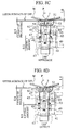
- At least one or desirably a plurality of bending angle detecting devices 27 shown in Figure 3 for detecting a bending angle of the workpiece W are mounted to the gaps between the adjacent divided dies Ds arranged in suitable positions of the die holder 9 in the longitudinal direction.
- the bending angle detecting device 27 of the first embodiment composing a main section of the present invention is provided with a detecting device main body 29 at the gap between the adjacent divided dies Ds detachably, and a base portion 31 at the lower portion of the detecting device main body 29 can be attached and detached to/from the die holder 9, and, for example, a pin shaft 35 as a lifting member which is guided by a guide section 37 is provided at an approximately center of a supporting section 33 at the upper portion of the detecting device main body 29 so as to be movable up and down.
- the lower portion of the pin shaft 35 is provided with a first engagement member 39 having engagement portions protruding left and right as shown in Figure 1, and the pin shaft 35 is normally biased upward with respect to the detection device main body 29 by, for example, a first spring 41, as a first elastic body.
- the pin shaft 35 is arranged in an approximately center of a V groove width of the die D so that its forward end can be pressed against the bending portion of the workpiece W to be bent.
- the supporting section 33 of the detecting device main body 29 is provided with link members 43, which are positioned, respectively, on the left and right sides of the pin shaft 35 in Figure 3 and are engaged with the upper surface of the first engagement member 39, so that the link members 43 can be freely pivoted by link shafts 45.
- a stopper (not shown) for stopping the pivoting of the link members is provided so that the forward end of the pin shaft 35 is normally stopped in a lightly lower position than the upper surfaces of the divided dies Ds by the link members 43.
- the detecting device main body 29 is provided with a plate-shaped rotor supporting member 47, which has a V-shaped notched portion 47A at its upper portion, on the base portion 31 of the detecting device main body 29 so as to be movable up and down in a state that the rotor supporting member 47 is normally biased upward by, for example, two second springs 49 as second elastic bodies provided on the left and right sides of the first spring 41.
- Two approximately semicircular rotors 51 are borne on the left and right upper portions of the V-shaped notched portion 47A of the rotor supporting member 47 by pivots 53.
- arc linear portions of the rotors 51 are workpiece contact portions 55 which come in contact with the linear portion of the flange section of the workpiece W, and they follow the workpiece W to be bent so as to detect the bending angle.
- a gap between the pivots 53 of the two rotors 51 is wider than the V groove of the divided dies Ds.
- the rotors 51 are provided with slots 57 on concentric circles about the pivots 53, and guide pins 59 which insert into the slots 57 protrude from the rotor supporting member 47. Therefore, the rotors 51 are guided by the guide pins 59, respectively, so as to be capable of rotating stably.
- left and right engagement members 61 and 63 as second engagement members are mounted integrally with the rotor supporting member 47 so a to be opposed to the left and right of the supporting section 33 of the detecting device main body 29, and the rotor supporting member 47 is normally biased upward by the two left and right second springs 49 provided to the base portion 31 via left and right engagement members 61 and 63, respectively.
- a total biasing force of the two second springs 49 are weaker than an biasing force of the first spring 41.
- engagement concave portions 65 which are engaged with the link members 43 are provided to the left and right engagement members 61 and 63, respectively.
- the centers of the link members 43 are normally biased upward about the link shafts 45 by the first spring 41 via the first engagement member 39 of the pin shaft 35, and the right and left outer sides of the link members 43 in Fig. 3 are normally biased upward by the second springs 49 via the engagement concave portions 65 of the left and the right engagement members 61 and 63.
- the pin shaft 35 is normally positioned on the lifting end, and the left and right engagement members 61 and 63 are pressurized by the link members 43 so as to be positioned on the lowering end, in other words, the rotor supporting member 47 is positioned at the lowering end.
- the press brake 1 is in the state before starting the bending, namely, the forward end of the pin shaft 35 is positioned slightly below the upper surface of the die D at the lifting end of the pin shaft 35, and the workpiece contact portions 55 of the two left and right rotors 51 retreat below the upper surfaces of the divided dies Ds at the lowering end of the rotor supporting member 47.
- the pin shaft 35, the first spring 41, the two second springs 49 the rotor supporting member 47 and the two rotors 51 as well as the detecting device main body 29 can be inserted or detached into/from the gap between the adjacent divided dies Ds as shown in Figure 5.
- a tension spring 69 is mounted to a lower portion of the auxiliary base 67 and a linear scale 71 is fixed to the other end of the tension spring 69, and one end of a wire 73, for example, as a linear element is fixed to an outer peripheral surface of the rotor 51 from the upper end of the linear scale 71 via a plurality of wheels 75 in a state that, for example, the wire 73 is wound by 1/4 and half windings around the outer peripheral surfaces of the rotor 51.
- the other rotor 51 has the similar structure, and Figure 4 show the wire 73 and the plural wheels 75, but since a phase of this wire 73 shifts from that of the other wire 73 of one rotor 51, the rotors 51 do not interfere with each other.
- the wheel 75 at the center in Figure 4 is mounted to the outside of the guide section 37, namely, on this side with respect to the sheet surface of Figure 4.
- reading heads 77 as scale moving amount detecting devices for detecting a moving amount of the linear scales 71 are mounted to the vicinities of the linear scales 71, respectively, in the auxiliary base 67, and the reading heads 7 are connected with a control device 79 as shown in Figure 6.
- the two rotors 51 pivot according to the bending state of the workpiece W. Accordingly the wires 73 are drawn against the biasing forces of the tension springs 69, so that the linear scales 71 lifts. The moving amounts of the linear scales 71 are read by the reading heads 77 so that rotating amounts of the rotors 51 are detected, and the bending angle of the workpiece W is calculated by the control device 79 and instantly detected.
- a detecting line 81 which is connected with the control device 79 is wired on a bottom portion of the die holder 9. Since a signal line terminal 83 which is connected with the reading heads 77 is provided to the lower portion of the detecting device main body 29 of the bending angle detecting device 27 so as to be capable of coming in contact with the detecting line 81, the bending angle detecting device 27 can be inserted and easily mounted into the gap between the adjacent divided dies Ds with suitable interval so as to be capable of measuring an angle of at least one portion, desirably plural portions in the longitudinal direction of the workpiece W.
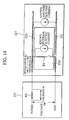
- a CPU 85 as a central processing unit is connected with an input device 87 as bending condition input means for inputting data such as a material, a plate thickness, a working shape, a mold condition, a target bending angle and a working program of the workpiece W, a display device 89 as a CRT display and a memory 91 for storing the input data.
- the CPU 85 is connected with a bending angle arithmetic unit 93 for calculating the bending angle based on signals from the reading heads 77 which read moving amounts of the linear scales 71 of the respective bending angle detecting devices 27.
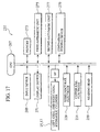
- Step S1 (At the time of locating the workpiece W, the angle of the workpiece W is 180°).
- the workpiece contact portions 55 of the two rotors 51 are retreated downward by, for example, about 0.5 mm from the upper surface of the die D. Therefore, before starting the bending, when the workpiece W is carried onto the divided dies Ds, the workpiece W does not interfere with the two rotors 51, so that the workpiece W is located smoothly.
- Step S2 (At the time of the initial bending, the angle of the workpiece W is in the vicinity of 170°).
- the workpiece W pushes the pin shaft 35 by 0.01 mm, namely, the so-called extent of pushing is 0.01 mm, but since the center portions of the workpiece contact portions 55 of the rotors 51 do not yet come in contact with the workpiece W, the bending angle of the workpiece W is not detected. This is the approaching stage.
- Step S3 (at the time of initial bending, the angle of the workpiece W is in the vicinity of 160°).
- the workpiece contact portions 55 of the rotors 51 are flush with the upper surface of the die D, and since the the rotors 51 do not follow the linear portion of the flange portion of the workpiece W, the contact between the rotors 51 and the workpiece W is not sufficient similarly to step S2, so that the angle of the workpiece cannot be detected by the rotors 51. This is the approaching stage.
- Step S4 (at the initial bending, the angle of the workpiece W is in the vicinity of 150°.
- Step S5 (at the time of initial bending, the angle of the workpiece W is in the vicinity of 120°).
- Step S6 (at the time of final bending, the angle of the workpiece W is in the vicinity of 90°).
- the outsides of the rotors 51 further rotate to move upward on the upper surface of the die similarly to the step S5, and the rotors 51 follow the leap-up of the flange portion of the workpiece W, and the arc linear portions as the workpiece contact portions 55 of the rotors 51 come in contact with the linear portion of the workpiece W, so that the bending angle of the workpiece W is calculated accurately.
- the bending angle is detected by at least one bending angle detecting device 27. Further, since the operation of the rotors 51 is only the rotation, the structure of the rotors 51 as the angle detecting sections is simplified and thus the measurement is made by the two rotors 51 so that the measuring accuracy is improved.
- the rotors 51 since the leap-up following mechanism of the workpiece W by means of the two rotors 51 is the spring elements such as the first and second springs 41 and 49, the rotors 51 respond to the movement of the workpiece W flexibly and instantly. Although the workpiece W is bent unstably with a certain tilt due to, for example, a difference in sliding conditions of the die shoulder R, since the two rotors 51 are arranged on the one rotor supporting member 47, the two rotors 51 follow the tilt at the process for bending the workpiece W. For this reason, the bending angle detecting device 27 is composed for each rotor 51 without separating them.
- the bending angle of the workpiece can be detected easily and accurately even at the bending which is carried out by a mold having a V groove with an unbalanced angle, a mold or the like in which R of different V-groove shoulder portion is arranged.
- the bending angle detecting device 27 does not depend upon mold conditions such as the groove width of the divided Dies Ds and R of the groove shoulder, namely, is independent.
- the rotors 51 have a semicircular shape and is provided with the arc linear type workpiece contact portions 55, the rotors 51 easily rotate so that the structure is simplified and thus the linear workpiece contact portions 55 easily follow the linear portion of the workpiece W.
- a bending angle detecting device 97 of a second embodiment composing the main section of the present invention will be explained in a manner that like members are designated by like numbers of the bending angle detecting device 27 of the first embodiment.
- a detecting device main body 99 can be inserted into and detached from the gap between the adjacent divided dies Ds similarly to the first embodiment, and it can be attached/detached to/from the die holder 9.
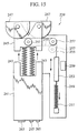
- the approximately center of an upper supporting section 101 of the detecting device main body 99 is provided with, for example, a pin shaft 103 as the lifting-lowering member via a guide section 105 so that the pin shaft 103 is movable up and down.
- the pin shaft 103 is arranged so that its forward end is pressed against the bending portion of the workpiece W.
- the lower portion of the pin shaft 103 is provided with a link engagement member 109 having, for example, a taper pressurizing section 107 as the engagement section at its left and right sides in Figure 10, and the pin shaft 103 is normally biased upward with respect to the detecting device main body 99 by a first spring 111 as a first elastic body.
- a first spring 111 as a first elastic body.
- the forward end of the pin shaft 103 is stopped in a position slightly lower than the upper surfaces of the divided dies Ds.
- a damper buffer member 115 having flange portions 113 on its left and right sides, respectively, is provided so as to slide the outer peripheral surface of the pin shaft 103 and freely lift and lower.
- guide members 119 which are normally biased by, for example, damper springs 117 as two damper elastic bodies are provided on the left and right, respectively.
- the guide members 119 is provided with notched portions 121, respectively, and the flange portions 113 of the damper buffer member 115 enter the notched portions, respectively, and the damper springs 117 are provided between the flange portions 113 and the upper surfaces of the notched portions 121 of the guide members 119. Therefore, an biasing force acts upon the flange portions 113 and the guide members 119 of the damper buffer member 115 to their repulsing direction due to the damper springs 117, but the insides of the notched portions 121 are formed with, for example, stepped portions 123 as stopper sections for constantly restraining the gaps between the damper buffer member 115 and the guide members 119 in the repulsing direction.
- the two left and right guide members 119 are provided integrally with a rotor supporting member 47 similarly to the first embodiment.
- the rotor supporting member 47 has a plate shape, and as shown in Figures 8 and 9, its upper portion has an approximately V shaped notched portion 47A.
- the rotor supporting member 47 bears the two approximately semicircular rotors 51 on the left and right upper portions of the V-shaped notched portion 47A, respectively, using the pivots 53.
- the bending angle arithmetic unit 93 for detecting the bending angle after the rotors 51 follow the workpiece to be bent and its function are similar to those in the first embodiment, the explanation thereof is omitted.
- the supporting section 101 of the detecting device main body 99 is provided with link members 125 which are positioned on the left and right sides of the pin shaft 103 in Figure 8 and whose one ends are engaged with the taper pressurizing sections 107 of the link engagement member 109 so that the link members 125 freely pivot by means of link shafts 127.
- the lower surfaces of the flange portions 113 of the damper buffer member 115 are placed on the other ends of the two left and right link members 125.
- the upper surfaces including the other ends of the two left and right link members 125 are normally in the approximately horizontal state, and the rotor supporting member 47, which is integral with the guide members 119 in which the flange portions 113 of the damper buffer member 115 are housed in the notched portions 121 via the damper springs 117, is lifted by the upper surfaces of the two left and right link members 125.
- the pin shaft 103 is positioned on the lift end by the biasing force of the first spring 111 so that the forward end of the pin shaft 103 is positioned slightly below the upper surfaces of the divided dies Ds.
- the two damper springs 117 function as damper. Namely, a speed at which bending linear portion of the workpiece W pushes down the pin shaft 103 according to the progress of the bending, in other words, a lift speed of the damper buffer member 115 lifting via the link members 125 is different from a speed at which the flange portion of the workplaces W leaps up, but the two damper springs 117 function as damper so as to absorb the lift difference. For this reason, the two rotors 51 follow the bending angle of the workpiece W securely so as to rotate.
- the rotating angle of the two rotors 51 is converted into the bending angle of the workpiece W by the bending angle arithmetic unit 27 so as to be detected instantly and accurately similarly to the first embodiment.
- a different point from the first embodiment is that since the lowering operation of the pin shaft 103 can enlarge the lift width of the rotor supporting member 47 by utilizing moments of the link members 125, the two second spring 49 of the first embodiment are not necessary, so that it is not necessary to further strengthen the biasing force of the first spring 111. As a result, the size of the first spring 111 can be greatly compact. Accordingly, there is a merit that the entire bending angle detecting device 97 can be compact.
- the size of the first spring 111 becomes large necessarily.
- the following mechanism composed of the two rotors is the spring element such as the second springs 49 and the damper springs 117, the following mechanism responds to the leap-up operation of the flange portion of the workpiece W flexibly and instantly.
- a press brake 201 of the present embodiment refers to the lowering type hydraulic press brake, but a lifting type press brake or a mechanical press brake such as crank which is not of the hydraulic type may be used.
- the lowering type hydraulic press brake 1 is mounted and fixed to the lower surface of, for example, the upper table 5 as a movable table movable up and down, namely a ram, via a plurality of intermediate plates 3 where the punches P are arrange with equal intervals.
- the die D is mounted and fixed to the upper surface of, for example, the lower table 7 as a fixed table via a die holder 9. Therefore, the upper table 5 lowers and the workpiece W as a plate material is bent between the punches P and the die D by the cooperation of the punches P and the die D.
- the left axial and right axial hydraulic cylinders 15 and 17 are provided to the upper portions of the left and right side frames 11 and 13 in Figure 2 composing the main body frame, and the upper table 5 is joined to the lower ends of the piston rods 19 of the left axial and right axial hydraulic cylinders 15 and 17.
- the lower table 7 is fixed to the lower portions of the left and right side frames 11 and 13, and the notched portions 21 are provided to the center portion of the lower table 7, and, for example, the crowning cylinders 23 and 25 (hydraulic cylinders) as the crowning device are provided in the notched portions 21, respectively. Pressurizing forces of pistons of the crowning cylinders 23 and 25 are controlled, so that a deflection amount of the center portion of the lower table 7 is adjusted.
- the lower table 7 is joined to a plurality of divided die holders 9 so that a network die holder 227 is structured.
- Two rail electrodes composed of a resistance rail electrode (Power) 229 and a copper rail electrodes 231 are wired on the bottom portion of the network die holder 227 approximately parallel, so that a part of a position detecting device 233 is structured.
- the resistance rail electrodes 229 of the adjacent die holders 9 are connected with each other and the copper rail electrodes 231 of the adjacent die holders 9 are connected with each other by connection cables 235.
- one end sides of the resistance rail electrodes 229 and one end sides of the copper rail electrodes 231 are connected with a control device 237 by an NC device or the like.
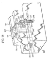
- the die D of the present embodiment is constituted so that the divided dies Ds are combine and joined as shown in Figure 16 and the die D is mounted to the network die holder 227.
- a plurality of angle sensor units 239 shown in Figure 15 as a plurality of bending angle detecting devices for detecting the bending angle of the workpiece W i.e. the three angle sensor units 239 in this embodiment are arranged in suitable positions in the longitudinal direction of the network die holder 227 and are mounted to gaps between the adjacent divided dies Ds.
- the angle sensor units 239 are mounted, as shown in Figure 12, so as to come in contact with the resistance rail electrodes 229 and the copper rail electrodes 231.
- the angle sensor units 239 are composed of a unit base 241 which can be inserted and detached into/from the gap between the adjacent divided dies Ds, a contact supporting plate 245 having a V shape which is normally biased upward at the upper portion of the unit base 241 via two compressing springs 243, and semicircular rotational contacts 247 which are borne to both sides of the V-shaped upper portion of the contact supporting plate 245.
- the two compressing springs 243, the contact supporting plate 245 and the two rotational contacts 247 as well as the unit base 241 can be inserted into and detached from the gap between the adjacent divided dies Ds as shown in Figure 16.
- an auxiliary base 249 is installed to the unit base 241 so as to positioned on the outside of the divide dies Ds in this embodiment.
- a linear scale 253 is fixed to the other end of a tension spring 251 whose one end is mounted to the lower portion of the auxiliary base 249, and, in a state that, for example, a wire 255 as a linear element is wound by 1/4 and half windings around outer peripheral surface of the rotational contact 247 via a plurality of wheels 257 from the upper end of the linear scale 253, one end of the wire 255 is fixed to the outer peripheral surface of the rotational contact 247.
- the other rotational contact 247 has the same structure, and in Figure 15 the wire 255 and the plural wheels 257 are shown by dotted lines.
- the two rotational contacts 247 are normally drawn downward by the tension spring 251, in the normal state, they are stopped by a stopper, not shown, so that the arc portions of the rotational contacts 247 are positioned in the horizontal state.
- the arc portions of the rotational contacts 247 are in a position which is approximately same as or slightly higher than the upper surface of the die D in the normal state.
- a reading head 259 as a scale moving amount detecting device for detecting a moving amount of the linear scale 253 is mounted to the vicinity of each linear scale 253 in the auxiliary base 249, and the reading heads 259 are connected with the control device 237.
- the two rotational contacts 247 pivot according to the bending state of the workpiece W, and accordingly the wires 255 are drawn against the biasing forces of the tension springs 251, so that the linear scales 253 lift.
- Moving amounts of the linear scales 253 are read by the reading heads 259, so that the rotating amounts of the rotational contacts 247 are detected, and the bending angle of the workpiece W is calculated by the control device 237 so as to be detected.
- a detecting line 261 which is electrically connected with the control device 237, as well as the above-mentioned resistance rail electrode 229 and the copper rail electrode 231 is wired.
- a signal line terminal 263 which is connected with the reading head 259 is provided to the lower portion of the unit base 241 of the angle sensor unit 239 so as to be capable of contacting with the detecting line 261, the angle sensor units 239 can be inserted and easily mounted into the gaps between the adjacent divided dies Ds with suitable intervals so as to be capable of measuring angles of plural places of the workpiece W in its longitudinal direction.
- a connecting terminal 265 which can come in contact with the resistance rail electrode 229 and the copper rail electrode 231 is also provided to the lower portion of the unit base 241.
- a CPU 267 as a central processing unit is electrically connected with, for example, an input device 269 as bending condition input means for inputting data such as a material, a thickness, a working shape, a mold condition, a target bending angle and a working program of the workpiece W, and a display device 271 such as a CRT display and a memory 273 for storing the input data.
- an input device 269 as bending condition input means for inputting data such as a material, a thickness, a working shape, a mold condition, a target bending angle and a working program of the workpiece W
- a display device 271 such as a CRT display and a memory 273 for storing the input data.
- the CPU 267 is connected with, for example, a first arithmetic unit 275 as a position calculating unit which are brought into conductive with the resistance rail electrode 229 and the copper rail electrode (ground-use rail electrode) 231 during the bending so as to calculate distances from reference position of the network die holder 227 to the angle sensor units 239, and with a second arithmetic unit 277 for calculating the bending angle based on signals from the reading heads 259 which read the moving amounts of the linear scales 253 of the angle sensor units 239.
- a first arithmetic unit 275 as a position calculating unit which are brought into conductive with the resistance rail electrode 229 and the copper rail electrode (ground-use rail electrode) 231 during the bending so as to calculate distances from reference position of the network die holder 227 to the angle sensor units 239
- a second arithmetic unit 277 for calculating the bending angle based on signals from the reading heads 259 which read the moving amounts of the linear scales 253 of the angle
- the CPU 267 is connected with a comparison judging device 279 for detecting the bending state of the workpiece W from the positions of the angle sensor units 239 obtained by the first arithmetic unit 275 and the bending angles of the workpiece W detected by the angle sensor units 239 at real time and comparing and judging the detected bending state of the workpiece W and a target angle so as to giving an instruction for adjusting the gaps between the punches P and the die D in order to carrying out suitable bending.
- a comparison judging device 279 for detecting the bending state of the workpiece W from the positions of the angle sensor units 239 obtained by the first arithmetic unit 275 and the bending angles of the workpiece W detected by the angle sensor units 239 at real time and comparing and judging the detected bending state of the workpiece W and a target angle so as to giving an instruction for adjusting the gaps between the punches P and the die D in order to carrying out suitable bending.
- a voltage Ep is applied to the resistance rail electrode 229 and the copper rail electrode 231.
- a shunt resistance Rs is provided to the resistance rail electrode 229 of the control device 237, and a voltage Es is applied to the shunt resistance Rs.
- the inside of the angle sensor unit 239 is connected with a resistance R1.
- a distance Lx from the reference position of the network die holder 227 to the angle sensor unit 239 is calculated from the resistance Rx of the resistance rail electrode 229.
- a packet for requesting ON of the resistance R1 is transmitted to the angle sensor unit 239 whose position is desired to be detected.
- the resistance R1 is ON only for a certain time.
- the voltage Es and the voltage Ep are measured within the time for which the resistance R1 is ON.
- a packet for requesting OFF of the resistance R1 is transmitted.
- the packets for ON and OFF are transmitted to the desired angle sensor unit 239 so that the shaft resistance Rs and the resistance R1 are measured.
- the resistance Rx is calculated based on the following equation (1) by using the voltage Es, the voltage Ep, and the measured results of the shaft resistance Rs and resistance R1.
- Rx Rs (Ep/Es-1) - R1
- the distance Lx from the reference position of the network die holder 227 to the angle sensor unit 239 becomes Rx / 1 (unit: m) from Rx obtained in the above manner.
- the operator combines the divided dies Ds and arranges the die D based on the bending information of the workpiece W at the time of the arrangement work, and in this embodiment, the three angle sensor units 239 are arranged in suitable positions of the network die holder 227 in its longitudinal direction.
- Lower connecting terminals 265 of the unit bases 241 of the three angle sensor units 239 come in contact with the resistance rail electrode 229 and the copper rail electrode 231 on the bottom portion of the network die holder 227, and signal line terminals 263 of the lower portions of the unit bases 241 also come in contact with the detecting line 261 on the bottom portion of the network die holder 227.
- the positions of the angle sensor units 239 are detected automatically.
- the workpiece W is located and set on the die D, and the punches P lower so that the workpiece W is bent.
- the bending angles and the tilt of the workpiece W are measured at real time by the angle sensor units 239 so as to be transmitted to the control device 237 during the bending.
- the bending angles received by the angle sensor units 239 are judged by the comparison judging device 279 as to whether or not the bending angles reach the target angle.
- the pressurizing forces of the pistons of the crowning cylinders 23 and 25 as the crowning devices are controlled and the deflection amount of the lower table 7 is adjusted so that the gaps between the punches P and the die D are finely adjusted.
- the left axial and right axial hydraulic cylinders 15 and 17 are controlled and a stroke of the upper table 5 is controlled so that the minimum unit of the gaps between the punches P and the die D is transmitted.
- the bending angles reach the target angle, the bending is ended.
- the positions of the angle sensor units 239 arranged by the arrangement work are automatically detected and the bending angles of the workpiece W are detected by the angle sensor units 239 at real time, the bending state of the workpiece W is detected at real time.
- a ram driving amount (compensation amount) and a crowning amount are calculated easily in order to obtain accuracy of go-angle. Therefore, since the gaps between the punches P and the die D can be finely adjusted accurately based on the calculated ran driving amount (compensation amount) and crowning amount, a product with highly accurate bending angle can be worked.
- a copper line 281 (corresponding to the copper rail electrode 231) and a resistance line 283 (corresponding to the resistance rail electrode 229) are wired parallel in a vicinity position of the die D of the lower table 7 so as to face the longitudinal direction of the lower table 7 and not to come in contact with each other in a coating body 285.
- One end sides of the copper line 281 and the resistance line 283 are electrically connected with the control device 237 similarly to the copper rail electrode 231 and the resistance rail electrode 229 of the aforementioned embodiment.
- the operator pressurizes a portion of the coating body 285 corresponding to one of the copper line 281 and the resistance line 283 to the other direction using fingers, so that the copper line 281 and the resistance line 283 are short-circuited. At this time, an electric current according to the short-circuited position flows in the copper line 281 and the resistance line 283.
- the operator pushes the coating body 285 in the position of the angle sensor unit 239 whose position is desired to be detected through the fingers so that the copper line 281 and the resistance line 283 are short-circuited, thereby easily obtaining the distance from the reference position to the position the angle sensor unit 239 and easily inputting the position of the angle sensor unit 239.
- the other members of this embodiment are similar to those in the aforementioned embodiments, and although the positions of the angle sensor units 239 are detected automatically in the former embodiments and the positions are detected by easy manual input in the latter embodiment, their functions and effects are approximately similar.
- the present invention is not limited to the aforementioned plural embodiments, suitable modification and alternation can be carried out so that the invention can be carried out in another embodiments.
- the upper table moves up and down in the aforementioned embodiments, but the lower table may be moved up and down so that the bending is carried out.
Landscapes
- Engineering & Computer Science (AREA)
- Mechanical Engineering (AREA)
- Bending Of Plates, Rods, And Pipes (AREA)
Abstract
Description
Claims (13)
- A bending apparatus reciprocating any one of an upper table to which a punch is mounted and a lower table to which a die is mounted so as to bend a workpiece according to cooperation of the punch and the die which is a plurality of adjacent divided dies extending along a longitudinal direction of the punch and corresponding to the punch, comprising:at least one bending angle detecting device, provided between the adjacent divided dies, for detecting a bending angle of the workpiece;a detecting device main body for being capable of inserting and detaching the bending angle detecting device into/from a gap of the adjacent divided dies;a lift member which is normally biased upward by a first elastic body in the detecting device main body and can be pressurized by a bending portion of the workpiece at an approximately center of a groove portion of the divided dies and has a first engagement member;a rotor supporting member which is normally biased upward by two second elastic bodies having smaller biasing forces than that of the first elastic body at left and right sides of the detecting device main body and has second engagement members;two rotors which are borne to both sides of a groove widthwise direction of the divided dies at the upper portion of the rotor supporting member and has workpiece contact portions which come in contact with the workpiece;link members which are engaged with the first engagement member so as to stop the upper end of the lift member in a position lower than the upper surfaces of the divided dies and are engaged with engagement concave port ions of the second engagement members so as to position the workpiece contact portions of the two rotors below the upper surfaces of the dies and which are provided to the detecting device main body rotatively; anda bending angle arithmetic unit for converting rotating amounts of the two rotors into bending angles of the workpiece.
- A bending apparatus reciprocating any one of an upper table to which a punch is mounted and a lower table to which a die is mounted so as to bend a workpiece according to cooperation of the punch and the die which is a plurality of adjacent divided dies extending along a longitudinal direction of the punch and corresponding to the punch, comprising:at least one bending angle detecting device, provided between the adjacent divided dies, for detecting a bending angle of the workpiece;a detecting device main body for being capable of inserting and detaching the bending angle detecting device into/from a gap of the adjacent divided dies;a lift member which is normally biased upward by a first elastic body in the detecting device main body and can be pressurized by a bending portion of the workpiece at an approximately center of a groove portion of the divided dies and has a link engagement member;a damper buffer member provided on an outer peripheral side of the lift member so as to freely lift and lower;guide members which are normally biased upward by two damper elastic bodies at the left and right sides of the damper buffer member, respectively;link members in which their one ends are engaged with the link engagement members lowering according to the lift member and the other ends are engaged with a lower surface of the damper buffer member so as to lift the damper buffer member and which are provided to the detecting device main body rotatively;a rotor supporting member provided integrally with the guide members;two rotors which are borne to both sides of a groove widthwise direction of the divided dies at the upper portion of the rotor supporting member and has workpiece contact portions which come in contact with the workpiece; anda bending angle arithmetic unit for converting rotating amounts of the two rotors into bending angles of the workpiece.
- The bending apparatus according to claim 1, wherein a gap between pivots of the two rotors are wider than a groove width of the divided dies.
- The bending apparatus according to claim 2, wherein a gap between pivots of the two rotors is wider than a groove width of the divided dies.
- The bending apparatus according to claim 3, wherein the rotors have a semicircular shape having the arc linear type workpiece contact portions.
- The bending apparatus according to claim 2, further comprising stopper sections, provided to the guide members, for constantly restraining a gap in a direction where the guide members and the damper buffer members repel each other due to the biasing forces of the two damper elastic bodies.
- A bending method of reciprocating any one of an upper table to which a punch is mounted and a lower table to which a die is mounted via a die holder so as to bend a workpiece according to cooperation of the punch and the die, comprising the steps of:previously wiring two rail electrodes composed of a resistance rail electrode and a ground-use rail electrode in a longitudinal direction of the die holder;arranging a plurality of bending angle detecting devices for detecting a bending angle of the workpiece in suitable positions in the longitudinal direction of the die holder;bringing the plural bending angle detecting devices into contact with the two rail electrodes;making the two rail electrodes into conductive during the bending so as to measure resistance values of the resistance rail electrodes from a reference position of the die holder to the bending angle detecting devices;calculating positions of the bending angle detecting devices based on the resistance values;detecting bending angles of the workpiece at real time using the bending angle detecting devices; andcarrying out the bending so that the bending angles of the workpiece in the bending angle detecting devices reach a target angle.
- A bending method of of reciprocating any one of an upper table to which a punch is mounted and a lower table to which a die is mounted via a die holder so as to bend a workpiece according to cooperation of the punch and the die, comprising the steps of:previously wiring a resistance line and an electric wire approximately parallel in a coating body in a longitudinal direction of the lower table so as not to normally come in contact with each other;arranging a plurality of bending angle detecting devices for detecting a bending angle of the workpiece in suitable positions in a longitudinal direction of the die holder;bringing the resistance line and the electric wire into conductive during the bending;externally pushing the plural bending angle detecting devices so as to bring the resistance line and the electric wire into contact with each other;converting resistance values from a reference position of the lower table to the bending angle detecting devices into distances using an electric current flowing at the above step;detecting bending angles of the workpiece at real time using the bending angle detecting devices; andcarrying out the bending so that the bending angles of the workpiece in the bending angle detecting devices reach a target angle.
- The bending method according to claim 7 or 8, wherein a crowning amount is adjusted so that the bending angles of the workpiece in the bending angle detecting devices are made to be uniform.
- A bending apparatus for reciprocating any one of an upper table to which a punch is mounted and a lower table to which a die is mounted via a die holder so as to bend a workpiece according to cooperation of the punch and the die, comprising:wherein in the above structure the comparison judging device compares the detected bending state of the workpiece with a target angle and judges the comparison so as to give an instruction for adjusting the gaps between the punch and the die so as to carry out suitable bending.two rail electrodes composed of a resistance rail electrode wired in a longitudinal direction of the die holder and a ground-use rail electrode;a plurality of bending angle detecting devices to detect bending angles of the workpiece, which are arranged in suitable positions in the longitudinal direction of the die holder so as to come in contact with the two rail electrodes;a position calculating unit to bring the two rail electrodes into conductive during the bending so as to measure resistance values of the resistance rail electrodes and calculate distances of a reference position of the die holder to the bending angle detecting devices based on the measured resistance values; anda comparison judging device to detect a bending state of the workpiece from positions of the bending angle detecting devices obtained by the position calculating unit and the bending angles of the workpiece detected at real time by the bending angle detecting devices,
- A bending apparatus for reciprocating any one of an upper table to which a punch is mounted and a lower table to which a die is mounted via a die holder so as to bend a workpiece according to cooperation of the punch and the die, comprising:wherein in the above structure the comparison judging device compares the detected bending state of the workpiece with a target angle and judges the comparison and giving an instruction for adjusting gaps between the punch and die so that suitable bending is carried out.a position detecting device which is constituted so that a resistance line and an electric wire are wired approximately parallel in a coating body extending to a longitudinal direction of the lower table so as not to normally contact with each other;a plurality of bending angle detecting devices, to detect a bending angle of the workpiece, arranged in suitable positions in a longitudinal direction of the die holder;a position calculating unit to calculate a distance from a reference position of the lower table to the contact position between the resistance line and the electric wire based on an electric current which flows when the resistance line and electric wire are brought into conductive during the bending and the plural bending angle detecting devices are externally pushed so that the resistance line and electric wire are brought into contact with each other; anda comparison judging device to detect a bending state of the workpiece from the positions of the bending angle detecting devices obtained by the position calculating unit and the bending angles detected at real time by the bending angle detecting devices,
- The bending apparatus according to claim 10, wherein each of the bending angle detecting devices is composed of:a unit base which can be inserted and detached into/from the gap between the adjacent divided dies;a contact supporting plate which is normally biased upward at the upper portion of the unit base via springs;two semicircular rotational contacts which are borne to both sides of the die widthwise direction at a center of a die groove portion at the upper portion of the contact supporting plate;linear scales which are biased to be drawn freely movable via linear elements, whose one ends are fixed and wound around outer peripheral surfaces of the two rotor contacts, so that arc portions of the two rotor contacts are normally approximately parallel with the upper surface of the die and are approximately flush with the upper surface of the die; andscale moving amount detecting devices to detect moving amounts of the linear scales.
- The bending apparatus according to claim 11, wherein each of the bending angle detecting device is composed of:a unit base which can be inserted and detached into/from the gap between the adjacent divided dies;a contact supporting plate which is normally biased upward via springs to the upper portion of the unit base;two semicircular rotational contacts which are borne to both ends of the widthwise direction of the die at a center of a groove portion of the die at the upper portion of the contact supporting plate;linear scales which are biased to be drawn movably via linear elements, whose one ends are fixed to and wound around outer peripheral surfaces of the two rotational contacts, so that arc portions of the two rotational contacts are normally approximately parallel with the upper surface of the die and are approximately flush with the upper surface of the die; andscale moving amount detecting devices to detect moving amounts of the linear scales.
Applications Claiming Priority (7)
| Application Number | Priority Date | Filing Date | Title |
|---|---|---|---|
| JP2000244545 | 2000-08-11 | ||
| JP2000244545 | 2000-08-11 | ||
| JP2000270580 | 2000-09-06 | ||
| JP2000270580A JP4683698B2 (en) | 2000-09-06 | 2000-09-06 | Bending method and apparatus |
| JP2000403383 | 2000-12-28 | ||
| JP2000403383A JP4643001B2 (en) | 2000-08-11 | 2000-12-28 | Bending machine |
| PCT/JP2001/006817 WO2002013987A1 (en) | 2000-08-11 | 2001-08-08 | Bending method and device therefore |
Publications (3)
| Publication Number | Publication Date |
|---|---|
| EP1319450A1 true EP1319450A1 (en) | 2003-06-18 |
| EP1319450A4 EP1319450A4 (en) | 2006-02-15 |
| EP1319450B1 EP1319450B1 (en) | 2008-05-28 |
Family
ID=27344330
Family Applications (1)
| Application Number | Title | Priority Date | Filing Date |
|---|---|---|---|
| EP01955591A Expired - Lifetime EP1319450B1 (en) | 2000-08-11 | 2001-08-08 | Bending apparatus |
Country Status (7)
| Country | Link |
|---|---|
| US (1) | US6959573B2 (en) |
| EP (1) | EP1319450B1 (en) |
| KR (1) | KR100527822B1 (en) |
| CN (1) | CN1262366C (en) |
| DE (1) | DE60134243D1 (en) |
| TW (1) | TW544346B (en) |
| WO (1) | WO2002013987A1 (en) |
Cited By (2)
| Publication number | Priority date | Publication date | Assignee | Title |
|---|---|---|---|---|
| AT512282A4 (en) * | 2012-06-18 | 2013-07-15 | Trumpf Maschinen Austria Gmbh | Bending press with angle detection device |
| AT515231A1 (en) * | 2014-01-09 | 2015-07-15 | Trumpf Maschinen Austria Gmbh | Lower tool of a bending press with a bending angle measuring device |
Families Citing this family (48)
| Publication number | Priority date | Publication date | Assignee | Title |
|---|---|---|---|---|
| US6829428B1 (en) * | 1999-12-28 | 2004-12-07 | Elias R. Quintos | Method for compact disc presentation of video movies |
| US7426789B2 (en) * | 2001-12-31 | 2008-09-23 | Engineered Devices & Solutions, Llc | Universal measuring apparatus and associated methods |
| JP4582621B2 (en) * | 2003-06-23 | 2010-11-17 | 株式会社アマダ | Bending machine |
| US7454943B2 (en) * | 2003-07-15 | 2008-11-25 | Tooling Innovations, Inc. | Articulated bending brake for sheet metal forming |
| JP2006205256A (en) * | 2004-12-27 | 2006-08-10 | Amada Co Ltd | Work bending angle detecting device and work bending machine |
| US8159550B2 (en) * | 2006-06-22 | 2012-04-17 | Apple Inc. | Presenting images as mosaics |
| US8180114B2 (en) * | 2006-07-13 | 2012-05-15 | Northrop Grumman Systems Corporation | Gesture recognition interface system with vertical display |
| DE102010012063A1 (en) * | 2010-03-19 | 2011-09-22 | Sms Meer Gmbh | Method for producing slotted tubes from sheet metal plates on a tube bending press and tube bending press |
| CN102248037A (en) * | 2011-05-31 | 2011-11-23 | 苗朋飞 | Bender locating device |
| GB201114438D0 (en) * | 2011-08-22 | 2011-10-05 | Airbus Operations Ltd | A method of manufacturing an elongate component |
| KR101379438B1 (en) * | 2012-04-19 | 2014-03-28 | 김경효 | Monitorinr system and method for wire drawing machine |
| CN102997888A (en) * | 2012-12-24 | 2013-03-27 | 南京埃斯顿自动化股份有限公司 | Real-time bending machine bending angle measurement device with angular displacement sensors |
| CN103316961B (en) * | 2013-07-11 | 2015-09-09 | 南京埃斯顿自动化股份有限公司 | A kind of device of real-time automatic measuring bending angle |
| AT514769B1 (en) * | 2013-09-02 | 2015-05-15 | Trumpf Maschinen Austria Gmbh | Bending machine, and method for bending a sheet metal workpiece |
| CN103962457B (en) * | 2014-05-20 | 2016-10-05 | 安徽联盟模具工业股份有限公司 | Bender lower die tool, stacked combination are without impression bending lower die device |
| CN105081081B (en) * | 2014-05-21 | 2017-05-10 | 青岛海尔模具有限公司 | Inserted-block structure and mold of sheet-metal door shell |
| CN105437524A (en) * | 2014-05-27 | 2016-03-30 | 致伸科技股份有限公司 | Electrode layer bending device of induction system |
| DE102014116386A1 (en) * | 2014-11-10 | 2016-05-12 | Trumpf Maschinen Austria Gmbh & Co.Kg. | Bending press and feeding device for a bending press |
| AT516043B1 (en) | 2014-11-12 | 2016-02-15 | Trumpf Maschinen Austria Gmbh | Bending press and feeding device for a bending press |
| CN104438853B (en) * | 2014-12-14 | 2016-08-17 | 马鞍山市国菱机械刃模有限公司 | A kind of manufacture method without indentation bending machine die |
| CN104624812A (en) * | 2015-03-04 | 2015-05-20 | 芜湖新联造船有限公司 | Machining die of ship waist-shaped hole reinforcing ring component |
| KR101748964B1 (en) | 2015-12-08 | 2017-06-20 | 김대희 | Material bending machine |
| CN105964741A (en) * | 2016-05-27 | 2016-09-28 | 中山市甜美电器有限公司 | Frame folding mechanism and frame folding machine |
| CN106378367A (en) * | 2016-08-25 | 2017-02-08 | 河南飞龙(芜湖)汽车零部件有限公司 | Small manual bending machine |
| CN106393770A (en) * | 2016-10-27 | 2017-02-15 | 安徽新荣钢构有限公司 | Self-holding type punching device |
| JP6377264B1 (en) * | 2016-11-02 | 2018-08-22 | 株式会社フライト | Step bending mold |
| CN106563715B (en) * | 2016-11-03 | 2018-12-04 | 山东大学 | The multi-functional v-shaped bending mold of plate Electroplastic and system |
| CN106312341B (en) * | 2016-11-11 | 2017-12-08 | 北京工业大学 | Frock clamp, device and method for cutting edge roundness processing |
| KR101973082B1 (en) * | 2017-05-26 | 2019-04-26 | 이문희 | Bending apparatus of U-type member for suspension system of vehicle |
| CN107081353A (en) * | 2017-06-23 | 2017-08-22 | 四川宇桥铁塔有限公司 | The adjustable metal plate part decompressor of bending angle |
| KR101957883B1 (en) * | 2017-11-30 | 2019-03-13 | 송승호 | Rectangular panel bending device |
| CN108453157A (en) * | 2018-01-15 | 2018-08-28 | 江阴协圣精密科技有限公司 | A kind of Bending Mould and the automation bending equipment comprising it |
| KR101909965B1 (en) * | 2018-05-10 | 2018-10-19 | (주)경남금속 | An Angle Calibration Device |
| JP7081690B2 (en) * | 2019-01-17 | 2022-06-07 | 日本製鉄株式会社 | Manufacturing method of press-molded products and press line |
| CN110102610B (en) * | 2019-05-31 | 2020-07-28 | 佛山市兴威五金有限公司 | Electric balance adjusting device of bending machine |
| US12397335B2 (en) * | 2019-06-07 | 2025-08-26 | Amada Co., Ltd. | Bending system |
| CN111112458B (en) * | 2019-12-31 | 2021-08-27 | 东莞盛翔精密金属有限公司 | Mold adjustment system and mold adjustment method |
| CN111014366A (en) * | 2020-03-09 | 2020-04-17 | 山东炎黄工业设计有限公司 | Thin plate bending device and using method thereof |
| CN112517696A (en) * | 2020-11-04 | 2021-03-19 | 广东创明遮阳科技有限公司 | Portable multi-angle rail bending machine |
| CN112893532B (en) * | 2021-02-20 | 2023-07-14 | 陕西得龙金属加工制品有限公司 | A sheet metal multi-angle bending device |
| CN113145695B (en) * | 2021-03-09 | 2022-07-26 | 陕西凯盛航空装备制造有限公司 | Bending device is used in aviation spare part production convenient to maintain |
| CN113083951B (en) * | 2021-03-17 | 2023-01-17 | 深圳市同德晟金属制品有限公司 | Iron sheet bending equipment for high-end equipment |
| CN113020341B (en) * | 2021-04-25 | 2023-04-18 | 淄博汇杰机械有限公司 | High-end equipment is made with panel beating shell equipment of bending |
| EP4088833A1 (en) * | 2021-05-12 | 2022-11-16 | Bystronic Laser AG | Bending machine, in particular press brake, with a safety system |
| CN114210781B (en) * | 2021-11-29 | 2023-09-05 | 江苏盛翔电子科技有限公司 | Bending equipment for honeycomb panel core material production |
| CN115446163B (en) * | 2022-11-10 | 2023-03-14 | 潍坊工程职业学院 | Bending forming assembly for machining V-shaped plates |
| CN116809773B (en) * | 2023-07-19 | 2025-08-08 | 巢湖市鼎力铁塔有限公司 | A bending equipment for angle steel production |
| CN117983701B (en) * | 2024-04-07 | 2024-06-14 | 高邮市龙华机械有限公司 | Stamping device of copper connecting piece for power equipment |
Family Cites Families (23)
| Publication number | Priority date | Publication date | Assignee | Title |
|---|---|---|---|---|
| NL8105266A (en) | 1981-11-20 | 1983-06-16 | Safan Maschf B V | Angle measuring device for bending press - automatically indicates angle between sides of sheet of metal during bending operation |
| US4571834A (en) | 1984-02-17 | 1986-02-25 | Orthotronics Limited Partnership | Knee laxity evaluator and motion module/digitizer arrangement |
| US4766675A (en) | 1986-06-10 | 1988-08-30 | Liu Bao Shen | Angle measuring instrument |
| JPS63157722A (en) | 1986-12-19 | 1988-06-30 | Toyo Koki:Kk | Bending device |
| US4864509A (en) * | 1987-09-29 | 1989-09-05 | The Boeing Company | Method and related apparatus for controlling the operation of a press brake |
| JPH0230327A (en) | 1988-07-15 | 1990-01-31 | Matsushita Electric Works Ltd | Stroke control device press brake |
| US5148693A (en) | 1989-11-14 | 1992-09-22 | Amada Company, Limited | Method and a device for detecting folding angles of a metal sheet during the folding and a method for folding of a metal sheet |
| JPH0713847Y2 (en) | 1990-02-16 | 1995-04-05 | 株式会社小松製作所 | Bending angle detector for press brake |
| CH689613A5 (en) | 1992-10-20 | 1999-07-15 | Beyeler Machines Sa | Device for measuring the bending angle of a sheet in a press. |
| JP2630720B2 (en) * | 1992-11-06 | 1997-07-16 | 丸機械工業株式会社 | Bending angle detecting device for plate material and method of operating press machine using the same |
| IT1260892B (en) * | 1993-02-23 | 1996-04-29 | Prima Ind Spa | DEVICE TO MEASURE THE CORNER OF A PIECE, IN PARTICULAR THE CORNER OF BENDING A PIECE OF SHEET METAL. |
| JP2752898B2 (en) | 1993-06-16 | 1998-05-18 | 株式会社小松製作所 | Springback angle measuring device in V-bending |
| JP2760371B2 (en) | 1994-06-13 | 1998-05-28 | 株式会社アマダメトレックス | Die for sheet bending machine |
| JP3797718B2 (en) * | 1996-10-14 | 2006-07-19 | 株式会社小松製作所 | Press brake |
| JP3338317B2 (en) | 1996-12-04 | 2002-10-28 | 株式会社アマダ | Die for sheet bending machine |
| JP4118975B2 (en) * | 1997-04-14 | 2008-07-16 | 株式会社アマダエンジニアリングセンター | Work tilt angle measuring method, work bend angle measuring method, work tilt amount measuring device, work bend angle measuring device |
| ES2172009T3 (en) * | 1997-06-20 | 2002-09-16 | Luciano Gasparini | FOLDING PRESS OF METAL SHEET. |
| JP4316695B2 (en) | 1998-02-20 | 2009-08-19 | 株式会社アマダ電子 | Bending angle measuring device |
| SE518599C2 (en) | 1998-06-26 | 2002-10-29 | Pullmax Ursviken Ab | Device for angle measurement |
| JP2000140944A (en) * | 1998-11-05 | 2000-05-23 | Amada Co Ltd | Spring-back calculating method, and folding device |
| KR100519521B1 (en) * | 1999-10-07 | 2005-10-05 | 무라타 기카이 가부시키가이샤 | A press machine and its driving method |
| ES2241566T3 (en) | 2000-01-24 | 2005-11-01 | Bystronic Laser Ag | PROCEDURE FOR REGULATION OF THE RACE OF A FOLDING PRESS. |
| JP3801466B2 (en) * | 2001-07-17 | 2006-07-26 | 株式会社東洋工機 | Bending method and bending apparatus |
-
2001
- 2001-08-08 US US10/343,836 patent/US6959573B2/en not_active Expired - Lifetime
- 2001-08-08 EP EP01955591A patent/EP1319450B1/en not_active Expired - Lifetime
- 2001-08-08 CN CNB018154840A patent/CN1262366C/en not_active Expired - Fee Related
- 2001-08-08 DE DE60134243T patent/DE60134243D1/en not_active Expired - Lifetime
- 2001-08-08 WO PCT/JP2001/006817 patent/WO2002013987A1/en not_active Ceased
- 2001-08-08 KR KR10-2003-7002002A patent/KR100527822B1/en not_active Expired - Fee Related
- 2001-08-10 TW TW090119577A patent/TW544346B/en not_active IP Right Cessation
Cited By (6)
| Publication number | Priority date | Publication date | Assignee | Title |
|---|---|---|---|---|
| AT512282A4 (en) * | 2012-06-18 | 2013-07-15 | Trumpf Maschinen Austria Gmbh | Bending press with angle detection device |
| AT512282B1 (en) * | 2012-06-18 | 2013-07-15 | Trumpf Maschinen Austria Gmbh | Bending press with angle detection device |
| WO2013188896A1 (en) * | 2012-06-18 | 2013-12-27 | Trumpf Maschinen Austria Gmbh & Co. Kg. | Bending press having an angle-measuring device and method for determining the bending angle |
| US9664493B2 (en) | 2012-06-18 | 2017-05-30 | Trumpf Maschinen Austria Gmbh & Co. Kg. | Bending press having an angle-measuring device and method for determining the bending angle |
| AT515231A1 (en) * | 2014-01-09 | 2015-07-15 | Trumpf Maschinen Austria Gmbh | Lower tool of a bending press with a bending angle measuring device |
| AT515231B1 (en) * | 2014-01-09 | 2015-09-15 | Trumpf Maschinen Austria Gmbh | Lower tool of a bending press with a bending angle measuring device |
Also Published As
| Publication number | Publication date |
|---|---|
| CN1262366C (en) | 2006-07-05 |
| US20040035178A1 (en) | 2004-02-26 |
| WO2002013987A1 (en) | 2002-02-21 |
| KR20030045783A (en) | 2003-06-11 |
| KR100527822B1 (en) | 2005-11-09 |
| US6959573B2 (en) | 2005-11-01 |
| EP1319450A4 (en) | 2006-02-15 |
| DE60134243D1 (en) | 2008-07-10 |
| TW544346B (en) | 2003-08-01 |
| EP1319450B1 (en) | 2008-05-28 |
| CN1455710A (en) | 2003-11-12 |
Similar Documents
| Publication | Publication Date | Title |
|---|---|---|
| US6959573B2 (en) | Bending method and device therefore | |
| EP0460441B1 (en) | Method of determining the quality of a crimped electrical connection | |
| EP0318437A1 (en) | Apparatus for checking dimensions of workpieces | |
| CN110918687A (en) | Aluminum plate straightening device | |
| JP2648647B2 (en) | Press-fit body press-fitting method and press-fit body with press-fit length measuring device | |
| JP4643001B2 (en) | Bending machine | |
| JP2001520121A (en) | A press bending apparatus comprising upper and lower beam deflection detection devices interacting with at least one crowning system. | |
| CN214747637U (en) | Size tolerance and geometric tolerance integrated stabilizer bar detection device | |
| CN209881882U (en) | Mobile phone side key measuring mechanism | |
| JP3156747B2 (en) | Bar material straightness correction device | |
| JPH03118934A (en) | Crimping press for crimping conduction terminal to conductor and method for measuring quality of crimped terminal end thereof | |
| JP4683698B2 (en) | Bending method and apparatus | |
| JP4325142B2 (en) | Press machine test method, test system, test program, and test program recording medium | |
| CN103480700B (en) | Automatic workpiece straightening device | |
| US11128095B2 (en) | Method for aligning a crimper of a first tool of a crimping press relative to an anvil of a second tool of the crimping press and a crimping press device | |
| EP4468474A1 (en) | Cylindrical battery beading equipment and beading method | |
| CN214667619U (en) | Medical treatment CT lathe slide rail endurance test device | |
| CN221559632U (en) | Relay contact pin connects presses detection adjustment equipment | |
| CN219425468U (en) | Stamping positioning mechanism | |
| JP3802183B2 (en) | Abutting positioning method of back gauge device, back gauge device and mold using this abutting positioning method | |
| CN113959307B (en) | Parallelism gauge based on envelope curve and detection method thereof | |
| JP3332352B2 (en) | Press equipment | |
| EP0964485A1 (en) | Crimp height measuring device | |
| CN212462320U (en) | Assembly cutting device of electronic wire harness connector | |
| CN121423458A (en) | An active bending mold |
Legal Events
| Date | Code | Title | Description |
|---|---|---|---|
| PUAI | Public reference made under article 153(3) epc to a published international application that has entered the european phase |
Free format text: ORIGINAL CODE: 0009012 |
|
| 17P | Request for examination filed |
Effective date: 20030307 |
|
| AK | Designated contracting states |
Designated state(s): AT BE CH CY DE DK ES FI FR GB GR IE IT LI LU MC NL PT SE TR |
|
| RBV | Designated contracting states (corrected) |
Designated state(s): CH DE FI FR GB IT LI |
|
| A4 | Supplementary search report drawn up and despatched |
Effective date: 20060102 |
|
| 17Q | First examination report despatched |
Effective date: 20060621 |
|
| RTI1 | Title (correction) |
Free format text: BENDING APPARATUS |
|
| GRAP | Despatch of communication of intention to grant a patent |
Free format text: ORIGINAL CODE: EPIDOSNIGR1 |
|
| GRAS | Grant fee paid |
Free format text: ORIGINAL CODE: EPIDOSNIGR3 |
|
| GRAA | (expected) grant |
Free format text: ORIGINAL CODE: 0009210 |
|
| AK | Designated contracting states |
Kind code of ref document: B1 Designated state(s): CH DE FI FR GB IT LI |
|
| REG | Reference to a national code |
Ref country code: GB Ref legal event code: FG4D |
|
| REG | Reference to a national code |
Ref country code: CH Ref legal event code: EP |
|
| REF | Corresponds to: |
Ref document number: 60134243 Country of ref document: DE Date of ref document: 20080710 Kind code of ref document: P |
|
| REG | Reference to a national code |
Ref country code: CH Ref legal event code: NV Representative=s name: ISLER & PEDRAZZINI AG |
|
| PLBE | No opposition filed within time limit |
Free format text: ORIGINAL CODE: 0009261 |
|
| STAA | Information on the status of an ep patent application or granted ep patent |
Free format text: STATUS: NO OPPOSITION FILED WITHIN TIME LIMIT |
|
| 26N | No opposition filed |
Effective date: 20090303 |
|
| PGFP | Annual fee paid to national office [announced via postgrant information from national office to epo] |
Ref country code: CH Payment date: 20110812 Year of fee payment: 11 |
|
| PGFP | Annual fee paid to national office [announced via postgrant information from national office to epo] |
Ref country code: GB Payment date: 20120824 Year of fee payment: 12 Ref country code: FI Payment date: 20120719 Year of fee payment: 12 |
|
| PGFP | Annual fee paid to national office [announced via postgrant information from national office to epo] |
Ref country code: DE Payment date: 20120808 Year of fee payment: 12 Ref country code: IT Payment date: 20120821 Year of fee payment: 12 Ref country code: FR Payment date: 20120711 Year of fee payment: 12 |
|
| REG | Reference to a national code |
Ref country code: CH Ref legal event code: PL |
|
| GBPC | Gb: european patent ceased through non-payment of renewal fee |
Effective date: 20130808 |
|
| PG25 | Lapsed in a contracting state [announced via postgrant information from national office to epo] |
Ref country code: CH Free format text: LAPSE BECAUSE OF NON-PAYMENT OF DUE FEES Effective date: 20130831 Ref country code: LI Free format text: LAPSE BECAUSE OF NON-PAYMENT OF DUE FEES Effective date: 20130831 Ref country code: FI Free format text: LAPSE BECAUSE OF NON-PAYMENT OF DUE FEES Effective date: 20130808 Ref country code: DE Free format text: LAPSE BECAUSE OF NON-PAYMENT OF DUE FEES Effective date: 20140301 |
|
| REG | Reference to a national code |
Ref country code: DE Ref legal event code: R119 Ref document number: 60134243 Country of ref document: DE Effective date: 20140301 |
|
| REG | Reference to a national code |
Ref country code: FR Ref legal event code: ST Effective date: 20140430 |
|
| PG25 | Lapsed in a contracting state [announced via postgrant information from national office to epo] |
Ref country code: IT Free format text: LAPSE BECAUSE OF NON-PAYMENT OF DUE FEES Effective date: 20130808 |
|
| PG25 | Lapsed in a contracting state [announced via postgrant information from national office to epo] |
Ref country code: GB Free format text: LAPSE BECAUSE OF NON-PAYMENT OF DUE FEES Effective date: 20130808 |
|
| PG25 | Lapsed in a contracting state [announced via postgrant information from national office to epo] |
Ref country code: FR Free format text: LAPSE BECAUSE OF NON-PAYMENT OF DUE FEES Effective date: 20130902 |