EP1318095A2 - A sheet conveying device having multiple outputs - Google Patents
A sheet conveying device having multiple outputs Download PDFInfo
- Publication number
- EP1318095A2 EP1318095A2 EP02027320A EP02027320A EP1318095A2 EP 1318095 A2 EP1318095 A2 EP 1318095A2 EP 02027320 A EP02027320 A EP 02027320A EP 02027320 A EP02027320 A EP 02027320A EP 1318095 A2 EP1318095 A2 EP 1318095A2
- Authority
- EP
- European Patent Office
- Prior art keywords
- sheet
- shaft
- pair
- rolls
- controller
- Prior art date
- Legal status (The legal status is an assumption and is not a legal conclusion. Google has not performed a legal analysis and makes no representation as to the accuracy of the status listed.)
- Granted
Links
Images


Classifications
-
- B—PERFORMING OPERATIONS; TRANSPORTING
- B65—CONVEYING; PACKING; STORING; HANDLING THIN OR FILAMENTARY MATERIAL
- B65H—HANDLING THIN OR FILAMENTARY MATERIAL, e.g. SHEETS, WEBS, CABLES
- B65H35/00—Delivering articles from cutting or line-perforating machines; Article or web delivery apparatus incorporating cutting or line-perforating devices, e.g. adhesive tape dispensers
- B65H35/02—Delivering articles from cutting or line-perforating machines; Article or web delivery apparatus incorporating cutting or line-perforating devices, e.g. adhesive tape dispensers from or with longitudinal slitters or perforators
-
- B—PERFORMING OPERATIONS; TRANSPORTING
- B65—CONVEYING; PACKING; STORING; HANDLING THIN OR FILAMENTARY MATERIAL
- B65H—HANDLING THIN OR FILAMENTARY MATERIAL, e.g. SHEETS, WEBS, CABLES
- B65H29/00—Delivering or advancing articles from machines; Advancing articles to or into piles
- B65H29/58—Article switches or diverters
- B65H29/60—Article switches or diverters diverting the stream into alternative paths
-
- B—PERFORMING OPERATIONS; TRANSPORTING
- B65—CONVEYING; PACKING; STORING; HANDLING THIN OR FILAMENTARY MATERIAL
- B65H—HANDLING THIN OR FILAMENTARY MATERIAL, e.g. SHEETS, WEBS, CABLES
- B65H2301/00—Handling processes for sheets or webs
- B65H2301/10—Selective handling processes
- B65H2301/13—Relative to size or orientation of the material
- B65H2301/131—Relative to size or orientation of the material single width or double width
-
- B—PERFORMING OPERATIONS; TRANSPORTING
- B65—CONVEYING; PACKING; STORING; HANDLING THIN OR FILAMENTARY MATERIAL
- B65H—HANDLING THIN OR FILAMENTARY MATERIAL, e.g. SHEETS, WEBS, CABLES
- B65H2301/00—Handling processes for sheets or webs
- B65H2301/20—Continuous handling processes
- B65H2301/23—Continuous handling processes of multiple materials in parallel to each other
-
- B—PERFORMING OPERATIONS; TRANSPORTING
- B65—CONVEYING; PACKING; STORING; HANDLING THIN OR FILAMENTARY MATERIAL
- B65H—HANDLING THIN OR FILAMENTARY MATERIAL, e.g. SHEETS, WEBS, CABLES
- B65H2301/00—Handling processes for sheets or webs
- B65H2301/30—Orientation, displacement, position of the handled material
- B65H2301/34—Modifying, selecting, changing direction of displacement
- B65H2301/341—Modifying, selecting, changing direction of displacement without change of plane of displacement
- B65H2301/3411—Right angle arrangement, i.e. 90 degrees
- B65H2301/34112—Right angle arrangement, i.e. 90 degrees changing leading edge
-
- B—PERFORMING OPERATIONS; TRANSPORTING
- B65—CONVEYING; PACKING; STORING; HANDLING THIN OR FILAMENTARY MATERIAL
- B65H—HANDLING THIN OR FILAMENTARY MATERIAL, e.g. SHEETS, WEBS, CABLES
- B65H2301/00—Handling processes for sheets or webs
- B65H2301/30—Orientation, displacement, position of the handled material
- B65H2301/36—Positioning; Changing position
- B65H2301/361—Positioning; Changing position during displacement
-
- B—PERFORMING OPERATIONS; TRANSPORTING
- B65—CONVEYING; PACKING; STORING; HANDLING THIN OR FILAMENTARY MATERIAL
- B65H—HANDLING THIN OR FILAMENTARY MATERIAL, e.g. SHEETS, WEBS, CABLES
- B65H2404/00—Parts for transporting or guiding the handled material
- B65H2404/10—Rollers
- B65H2404/14—Roller pairs
-
- B—PERFORMING OPERATIONS; TRANSPORTING
- B65—CONVEYING; PACKING; STORING; HANDLING THIN OR FILAMENTARY MATERIAL
- B65H—HANDLING THIN OR FILAMENTARY MATERIAL, e.g. SHEETS, WEBS, CABLES
- B65H2511/00—Dimensions; Position; Numbers; Identification; Occurrences
- B65H2511/50—Occurence
- B65H2511/51—Presence
- B65H2511/514—Particular portion of element
-
- B—PERFORMING OPERATIONS; TRANSPORTING
- B65—CONVEYING; PACKING; STORING; HANDLING THIN OR FILAMENTARY MATERIAL
- B65H—HANDLING THIN OR FILAMENTARY MATERIAL, e.g. SHEETS, WEBS, CABLES
- B65H2513/00—Dynamic entities; Timing aspects
- B65H2513/20—Acceleration or deceleration
-
- B—PERFORMING OPERATIONS; TRANSPORTING
- B65—CONVEYING; PACKING; STORING; HANDLING THIN OR FILAMENTARY MATERIAL
- B65H—HANDLING THIN OR FILAMENTARY MATERIAL, e.g. SHEETS, WEBS, CABLES
- B65H2701/00—Handled material; Storage means
- B65H2701/10—Handled articles or webs
- B65H2701/13—Parts concerned of the handled material
- B65H2701/131—Edges
- B65H2701/1311—Edges leading edge
-
- B—PERFORMING OPERATIONS; TRANSPORTING
- B65—CONVEYING; PACKING; STORING; HANDLING THIN OR FILAMENTARY MATERIAL
- B65H—HANDLING THIN OR FILAMENTARY MATERIAL, e.g. SHEETS, WEBS, CABLES
- B65H2701/00—Handled material; Storage means
- B65H2701/10—Handled articles or webs
- B65H2701/13—Parts concerned of the handled material
- B65H2701/131—Edges
- B65H2701/1313—Edges trailing edge
Definitions
- This invention relates to high-speed printers and more specifically, it relates to a sheet-conveying device that can output paper in multiple directions.
- Electrophotographic printing and reproduction devices are well known.
- a photoconductive member is charged to a uniform potential and thereafter exposed to a light image of an original document to be reproduced.
- the exposure discharges the photoconductive member in areas corresponding to the background of the document being reproduced and creates a latent image on the photoconductive member.
- a light beam is modulated and used to selectively discharge portions of the photoconductive member in accordance with image information.
- the latent image on the photoconductive member is visualized by developing the image with a developer powder commonly referred to as "toner.”
- developer which comprises both charged carrier particles and charged toner particles that triboelectrically adhere to the carrier particles.
- the toner particles are attracted from the carrier particles by the charged pattern of image areas on the surface of the photoconductive member to form a visualized toner image on the photoconductive member.
- This toner image is then transferred to a recording medium such as paper or the like for viewing by an end user.
- the toner is fixed to the surface of the paper through the application of heat and pressure.
- a piece of paper that has received an image may need to be decurled, embossed, perforated, slit, rotated, or stacked.
- the user may also want to use a variety of finishing applications such as staplers, tape binders, perfect binders, stitchers, and signature booklet makers. These applications require output to be in a particular orientation for proper operation of the equipment.
- post-image transfer modules capable of performing any of a wide variety of post-processing functions using the same b ase document h andling hardware, b ut also r eleasably receiving one or more post-processing modules that perform particular post-processing functions.
- some printing systems may output sheets two at a time in addition to, or instead of one at a time. This is known in the art as “two-up” or “2-up” delivery.
- One way to increase the speed of the printer, without increasing the speed of the xerographic module, is to print two-up.
- Printing two-up involves printing two images side-by-side on the same large sheet (11x17 for example). Then, after the images are transferred to the sheet, the sheet is fed into a slitter module, which slits the sheet into two smaller sheets (8.5 x 11). This method effectively doubles the output speed of a printer.
- the images on each side of the sheet can either be duplicates or prints from separate jobs.
- a sheet-conveying device having multiple outputs accepts the two sheets on input, slows them down until they hit a fixed wall, and then drives the sheets out 90° from the input direction. Thus, the sheets exit the sheet-conveying device having multiple outputs one after the other.
- Embodiments include a method of changing the direction of travel of first and second sheets exiting a device in a two-up configuration without using a registration wall, which includes sensing a trailing edge of the first sheet and a trailing edge of the second sheet; accelerating the first sheet in a first direction with a first pair of drive rolls; accelerating the second sheet in the first direction in tandem with the first sheet with a second pair of drive rolls; decelerating the first sheet and the second sheet until each of the first sheet and the second sheet substantially stop travelling in the first direction; retracting the first pair and second pair of drive rolls; extending a third pair and a fourth pair of drive rolls; accelerating the first sheet to a first speed in a second direction oriented approximately 90° to the first direction with the third pair of drive rolls; accelerating the second sheet to a second speed in a third direction with the fourth pair of drive rolls.
- a sheet conveying device having multiple outputs for sequencing two approximately identical sheets, each sheet having a leading edge and a trailing edge, wherein the sheets arrive in a two-up configuration, and wherein the sheet conveying device having multiple outputs has no registration wall, which includes a first pair of rolls; a second pair of rolls; a first shaft about which the first pair of rolls and the second pair of rolls rotate; a first servomotor operably connected to the first shaft, wherein the first servomotor rotates the first shaft; a third pair of rolls; a second shaft about which the third pair of rolls rotate, the second shaft oriented at an angle approximately 90° relative to the first shaft; a second servomotor operably connected to the second shaft, wherein the second se rvomotor rotates the second shaft; a fourth pair of rolls; a third shaft about which the fourth pair of rolls rotate, the third shaft oriented at an angle approximately 90° relative to the first shaft and approximately parallel to the second shaft; a third servomotor operably connected to the third shaft,
- the third pair of rolls and the fourth pair of rolls rotate in the same direction.
- the third pair of rolls and the fourth pair of rolls rotate in opposite directions.
- the device further comprises a second sensor connected to the controller, wherein the second sensor detects when the leading edge of the second sheet passes the second sensor.
- Still other embodiments include a method of changing the direction of travel of a sheet exiting a device without using a registration wall, and without rotating the sheet, which includes sensing a trailing edge of the sheet; accelerating the sheet in a first direction with a first pair of drive rolls; decelerating the sheet using the first servomotor until the sheet substantially stops travelling in the first direction; retracting the first pair of drive rolls; extending a second pair of drive rolls; and accelerating the sheet in a second direction oriented approximately 90° to the first direction with the second pair of drive rolls.
- the third direction is opposite the second direction.
- the first sheet and the second sheet are stopped such that they will be center registered upon entering a finishing module.
- first sheet and the second sheet are stopped such that they will be inboard registered upon entering a finishing module. In a further embodiment the first sheet and the second sheet are stopped such that they will be outboard registered upon entering a finishing module.
- a first servomotor accelerates the first pair of drive rolls and the second pair of drive rolls.
- a second servomotor accelerates the third pair of drive rolls.
- the fourth pair of drive rolls is accelerated by a third servomotor.
- Still other embodiments include a multi-path sheet conveying device having multiple outputs, which includes a first sensor located for detecting when a trailing edge of a first sheet passes the first sensor; a controller operably connected to the first sensor; a first shaft; a first pair of rolls rotatably connected to the first shaft; a first servomotor operably connected to the first shaft and to the controller, wherein the first servomotor rotates the first shaft; a second shaft oriented at an angle approximately 90° relative to the first shaft; a second pair of rolls rotatably connected to the second shaft; and a second servomotor operably connected to the second shaft and to the controller, wherein the second servomotor rotates the second shaft.
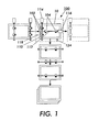
- FIGS. 1-5 illustrate an embodiment of a sheet-conveying device 100.
- Embodiments of this sheet direction changer do not use a registration wall, and do not rotate the printed sheet.
- the multi-path sheet direction changer can be connected in series to the output of, for example, a printer. However, this embodiment can be connected to any device that outputs sheets of paper.
- the embodiment o f the sheet illustrated i n FIGS. 1 - 5 includes two p airs o f drive rolls (102, 104) and two pairs of idlers (106, 108).
- the first pair of drive rolls 102 are rotatably connected to a first shaft 110.
- the second pair of drive rolls 104 are rotatably connected to a second shaft 112.
- the idlers are in turn connected to shafts 111 and 113 respectively.
- Two digitally controlled servomotors (servos) (114, 116) drive the first 110 and second 112 shafts, thereby rotating the rolls.
- the rolls can be any type of roll. I have used cylindrical rolls in the drawings for this invention, but this should not be considered limiting as spherical or other rolls can be used with this invention.
- the first servomotor 114 which will also be referred to as the 0° servo 114 for reference.
- the remaining servomotor will be referred to as the 90° servo 116.
- the drive roll pair 102 (and opposing idler pair 106) are located so that when the 0° servo 114 activates, each pair drives the incoming sheet into the sheet direction changer.
- a controller 120 starts and stops each of the servos.
- Embodiments of the system also include a servo control sensor 118.
- the sensor 118 can be located on the output of the device feeding paper to the sheet direction changer to detect when the (trail edge) TE of the sheet 10 exits the previous device.
- the sensor can also be located on the sheet direction changer to detect when the TE of the sheet 10 enters the sheet direction changer.
- the sensor 118 is operably connected to the controller 120. This connection can be electrical, optical, or any other method wherein a signal can be sent to the controller 120.
- the controller 120 receives the signal from the sensor and determines when to accelerate and when to stop the 0° and 90° servos based upon the signal, knowledge of the paper size, and knowledge of the finishing device to which output is being sent.
- Sheet size information can be provided to the controller 120 from operator input or from the sheet feeding tray or cassette selection, or other method.
- the controller can be programmed to associate certain paper sizes with certain trays.
- the controller 120 may have stored in its memory that tray 4 contains A4 paper. It would also have knowledge of the device to which the output is being sent. For example, the user could input what finishing device was attached. Given the tray number, the controller would know the paper size, and given the finishing device the controller would know what kind of registration was required. If the user, for example, selects tray 4 and an inserter for inserting, for example, cover stack into the stream, where the inserter required center registered input, the controller automatically stops and starts the servomotors to properly register A4 paper for the inserter.
- the controller 120 After receiving information about position and size of the sheet, the controller 120 first sends a signal to the 0° servo 114 to match the output speed of the printer (or whatever other device delivering sheets to the sheet direction changer) so that there is less chance of damage to the paper or of a jam being created.
- the servo 114 accelerates the rotation of the shaft 110 thereby accelerating drive roll pair 102.
- Drive roll pair 102 form nips with idler pair 106.
- the 0° servo 114 accelerates drive roll pair 102 once the TE of the sheet is out of the previous nip in order to increase the inter-copy gap (ICG) between the sheets in the nip and the following pair of slit sheets.
- ICG inter-copy gap
- the controller 120 then signals the 0° servo 114 to stop the sheets in a position where they will be properly registered for output.
- the sheets can be center, inboard (IB) or outboard (OB) registered. This is beneficial in that the multi-path sheet direction changer can then be used to input into any finishing device.
- the controller 120 sends a first signal to a first actuator 122 to retract the 0° idler pair 106 and a second signal to a second actuator 123 to extend the 90° idler pair 108.
- a first actuator 122 to retract the 0° idler pair 106
- a second signal to a second actuator 123 to extend the 90° idler pair 108.
- Any one of numerous types of actuators may be used to retract and extend the shafts (111, 113) to which the idlers are connected. There are multiple ways known in the art in which the extension and retraction of the idler rolls may be accomplished.
- FIGS. 2-5 illustrate shafts 111 and 113, each connected to an arm connected to a solenoid. It is known in the art to use solenoids to hold idler rolls in a retracted state until they are needed.
- the solenoids (122, 123) in FIGS. 2-5 in turn are connected to the controller 120.
- FIG. 6 shows in more detail an embodiment of a solenoid mechanism for retracting/extending the idler rolls.
- FIG. 6 also shows a spring bias system, which causes the shaft connected an idler to extend into a position where nips are formed when power to the solenoid is cut.
- the controller de-energizes the solenoid and the spring bias system engages the pair of idler rolls and causes nips to form between the drive rolls and the idler rolls.
- FIGS. 2-6 show the idlers raising to create a nip should not be considered limiting. The idlers could be lowered from above or extended in any other direction to form a nip.
- the solenoid actuation system can bed esigned so that the i dlers are engaged when the s olenoid i s energized and disengaged when the solenoid is de-energized.
- solenoid system shown and discussed is meant to be an exemplary embodiment of an actuating system.
- actuating system There are other methods for engaging and disengaging idlers that will be readily apparent to anyone reasonably skilled in the art.
- the methods disclosed herein should not b e considered limiting.
- the controller After the 0° idler pair 106 have been retracted and the 90° idler pair 108 have been extended, the controller starts up the 90° servo 116.
- the servo 116 ramps drive roll pair 104 up to a speed that matches the input speed of the finishing equipment.
- the sheet 10 is then driven into the first nip in the finishing system where it now is under control of that nip. Once the TE of the sheet 10 exits the sheet direction changer, the controller 120 turns the 90° servo off.
- a sensor 124 that is operably connected to the controller 120 informs the controller when the sheet 10 is exiting the sheet-conveying device.
- the second sensor 124 may be located at an exit point of the sheet direction changer as shown in FIGS. 1, 4, and 5 or the sensor 124 may be located at the entrance to the finisher.
- the sensor 124 can sense the TE or the lead edge of the paper as it passes.
- the controller 120 causes the 90° actuator 123 to disengage the 90° idler pair 108 while at the same time causing actuator 122 to reengage the 0° idler pair 106 and ramping up the 0° servo 114 to accept the next sheet entering the sheet direction changer.
- FIGS. 8 -12 illustrate another embodiment of a multi-path sequencer for use with two-up printing.
- the sheet-conveying device 200 having multiple outputs can be connected in s eries to the output o f, for example, a c onverting m odule including a slitter.
- the slitter may alternately be used to slit incoming paper so that a large sheet may be turned into two smaller sheets. For example, it can be used to turn an 11 x 17 sheet into two 8.5 x 11 sheets.
- the converting module can allow large sheets to pass through intact.
- a converting module is meant to be exemplary of a device to which this embodiment may be connected, but this embodiment be connected to any device that outputs sheets in a two-up format.
- the embodiment illustrated in FIGS. 8 - 12 includes four pairs of drive rolls (202, 204, 206, and 208) and four pairs of idlers (212, 214, 216, and 218).
- the first pair of drive rolls 202 and the second pair of drive rolls 204 are rotatably connected to a single first shaft 222.
- the third pair of drive rolls 206 are rotatably connected to a second shaft 224, and the fourth pair of rolls 208 are rotatably connected to a third shaft 226.
- Three digitally controlled servomotors (servos) (232, 234, 236) drive the first 222, second 224, and third 226 shafts, thereby rotating the rolls.
- the first servomotor 232 which will also be referred to as the 0° servo for reference.
- the remaining servomotors will be referred to as 90° servos 234, 236.
- the drive roll pairs 202, 204 (and opposing idler pairs 212, 214) are located so that when the 0° servo activates, each pair drives one of the two incoming sheets into the sequencer.
- a controller 242 starts and stops each of the servos.
- Embodiments of the system also include servo control sensor 244.
- the sensor 244 can be located on the output of the device feeding paper to the sequencer, most often a slitter for two-up prints, so as to detect when the (trail edge) TE of each of the sheets exits the previous device.
- the sensor 244 can also be located on the sequencer to detect when the TE of the sheets enters the sequencer.
- the sensor 244 is operably connected to the controller 242. This connection can be electrical, optical, or any other method wherein a signal can be sent to the controller.
- the controller 242 receives a signal from the sensor 244 and determines when to accelerate and when to stop the 0° and 90° servos based upon the signal, knowledge of the paper size (before or after slitting), and knowledge of the finishing device to which output is being sent. As noted with respect to the previously discussed embodiment there are myriad ways information regarding paper size and finisher type can be relayed to the controller.
- the controller After receiving information about position and size of the sheets, the controller first sends a signal to the 0° servo 232 to match the output speed of the slitter module so that there is less chance of damage to the paper or of a jam being created.
- the servo 232 accelerates the rotation of the shaft thereby accelerating drive roll pairs 202 and 204.
- Drive roll pairs 202 and 204 form nips with idler pairs 212 and 214.
- the 0° servo 232 accelerates drive roll pairs 202 and 204 once the TE of the sheet is out of the previous nip in order to increase the inter-copy gap (ICG) between the sheets in the nip and the following pair of slit sheets.
- ICG inter-copy gap
- the sheet conveying device having multiple outputs time to stop the two-up sheets and drive them out at an approximately 90° angle before the next pair of sheets enters.
- the controller then signals the 0° servo to stop the sheets in a position where they will be properly registered for output.
- the sheets can be center, inboard (IB) or outboard (OB) registered. This is beneficial in that the sheet-conveying device having multiple outputs can then be used to input into any finishing device.
- the controller 242 sends a signal to the 0° actuator 245 to retract the 0° idler pairs (212, 214). At the same time it sends a signal to the actuator 246 to extend the first 90° idler pair 216, and it sends a signal to the actuator 247 to extend the second 90° idler pairs 218.
- Any one of numerous types of actuators may be used to retract and extend the shafts (222, 224, 226) to which the idlers are connected. As discussed with respect to the embodiment disclosed in FIGS. 1-5, there are multiple ways known in the art in which the extension and retraction of the idler rolls may be accomplished.
- FIGS. 9-12 illustrate the 0° 222 and 90° (224, 226) shafts, each connected to an arm connected to a solenoid. It is known in the art to use solenoids to hold idler rolls in a retracted state until they are needed. The solenoids (245, 246, 247) in FIGS. 9-12 in turn are connected to the controller 242.
- FIG. 6 shows in more detail an embodiment of a solenoid mechanism for retracting/extending the idler rolls.
- FIG. 6 also shows a spring bias system, which causes the shaft connected an idler to extend into a position where nips are formed when power to the solenoid is cut. Again, the fact that FIGS. 9-12 show the idlers raising to create a nip should not be considered limiting.
- solenoid system shown and discussed is meant to be an exemplary embodiment of an actuating system.
- actuating system There are other methods for engaging and disengaging idlers that will be readily apparent to anyone reasonably skilled in the art.
- a cam mechanism such as that shown in FIG. 7, to engage and disengage each idler pair.
- the methods disclosed herein should not be considered limiting
- the controller starts up the two 90° servos.
- the servo 234 that is closer to the output of the sheet conveying device having multiple outputs is ramped up to a higher speed than the servo 236 further from the output so that separation can be created between the two sheets. This is done to help ensure that there is sufficient time for the finishing system following the sheet-conveying device having multiple outputs to handle the two sheets separately.
- the servo 234 ramps drive roll pair 206 up to a speed that matches the input speed of the finishing equipment.
- the sheet 204 is then driven into the first nip in the finishing system where it now is under control of that nip.
- Servo 236 rotates drive roll pair 208 so that it pushes the sheet 206 which is further from the output at a slower speed until the lead edge (LE) of the sheet is close to the drive roll 206 nip. At this point servo 236 speeds up to rotate drive roll pair 208 faster until drive roll pair 208 matches the speed of drive roll pair 206. This creates a smooth transition of the sheet between the two nip pairs. The second sheet is then driven out of the nip between drive roll pair 208 and idler pair 218 into the finishing device. Once the TE of the second sheet is out of the sheet conveyer, both the 90° servomotors turn off.
- a sensor 248 that is operably connected to the controller 242 informs the controller when both sheets have exited the sheet-conveying device.
- the second sensor 248 may be located at an exit point of the sheet direction changer as shown in FIGS. 8, 11, and 12 or the sensor 248 may be located at the entrance to the finisher.
- the sensor 248 can sense the TE or the lead edge of the second sheet of paper as it passes.
- the controller 242 causes the 90° actuators (246, 247) to disengage and retract the 90° idler rolls (216, 218) while at the same time causing the actuator 245 to reengage the 0° idler pairs (212, 214) and ramping up the 0° servo 232 to accept the next two sheets entering the sheet conveying device.
- the embodiments disclosed above also allow the user the option of having sheets pass straight through the sheet conveying device without a 90° direction change, which is not possible with sheet conveyers that used a fixed registration wall. This is especially beneficial for the two-up embodiment when customers do not want to slit the larger sheet and just want to stack it.
- the larger unslit sheet could pass straight through the sheet conveying device having multiple outputs and be in the proper orientation (long edge first) for most finishing or stacking devices.
- a user would send a command to the controller 242 informing it that a large sheet or large sheets were being printed.
- the controller 242 would cause the 0° servo to keep drive roll pairs (202, 204) rotating to keep driving the single large sheet forward.
- the 90° drive rolls would not be used when large sheets passed through the sequencer.
- This two-up embodiment also allows for drive roll pair 206 and drive roll pair 208 speeds to be reversed so the system could be used to drive sheets out 90° out the other side of the sheet conveying device having multiple outputs. This is beneficial in the case where a customer location better lends itself to a 90° turn heading left rather than right when looking at the input of the sheet-conveying device having multiple outputs. More generally, the sequencer allows all manner of configurations, cross-shaped, L-shaped, reverse L-shaped, etc.
- One embodiment allows sheets to be driven out in directions 90° left and right to the entrance direction as well as forward.
- This embodiment is illustrated in FIG. 13.
- the 90° drive roll pairs (206, 208) rotate in opposite directions to each other. Each pair then drives one sheet of a two-up pair out to a finishing device.
- a single large sheet entering the sheet-conveying device can be driven straight ahead by the 0°drive roll pairs (202, 204).
- the conveyer allows sheets to go in any of three different directions forward, clockwise, or counterclockwise.
- a user can greatly increase output rates for two-up prints.
- Two stackers located to the left and right of the sheet conveying device can stack sheets faster than a single stacker located to the left or right of the sheet conveying device.
- print output could be maintained at the same speed.
- This configuration could aid in relieving stress on the stackers or third party finishing equipment.
- Each stacker would see half as many sheets as it would if both sheets were driven in the same direction. This allows more time for the stacking function to occur and allows more time for the sheets to settle in each stack before the next sheet-enters. The same effect would be seen using any third party finishing equipment connected to both output ports.
- a stacker may be located in one direction, a signature booklet maker in a second direction, and a binder in a third direction.
- a small sheet stacker may be located to the left of the sheet conveying device, a large sheet stacker located directly opposite the paper feed side of the device, and a stitcher may be located off the right side. This allows for maximum flexibility for the customer.
Landscapes
- Engineering & Computer Science (AREA)
- Mechanical Engineering (AREA)
- Delivering By Means Of Belts And Rollers (AREA)
- Registering Or Overturning Sheets (AREA)
- Separation, Sorting, Adjustment, Or Bending Of Sheets To Be Conveyed (AREA)
Abstract
Description
In a further embodiment the device further comprises a second sensor connected to the controller, wherein the second sensor detects when the leading edge of the second sheet passes the second sensor.
In a further embodiment the third direction is opposite the second direction.
In a further embodiment the first sheet and the second sheet are stopped such that they will be center registered upon entering a finishing module.
In a further embodiment the first sheet and the second sheet are stopped such that they will be inboard registered upon entering a finishing module.
In a further embodiment the first sheet and the second sheet are stopped such that they will be outboard registered upon entering a finishing module.
In a further embodiment a first servomotor accelerates the first pair of drive rolls and the second pair of drive rolls.
In a further embodiment a second servomotor accelerates the third pair of drive rolls.
In a further embodiment the fourth pair of drive rolls is accelerated by a third servomotor.
Claims (10)
- A multi-path sheet conveying device having multiple outputs, comprising:wherein the first servomotor rotates the first shaft;a first sensor located for detecting when the trailing edge of the first sheet passes the first sensor;a controller operably connected to the first sensor;a first shaft;a first pair of rolls rotatably connected to the first shaft;a first servomotor operably connected to the first shaft and to the controller,a second shaft oriented at an angle approximately 90° relative to the first shaft;a second pair of rolls rotatably connected to the second shaft,a second servomotor operably connected to the second shaft and to the controller, wherein the second servomotor rotates the second shaft.
- The device of claim 1 further comprising a second sensor connected to the controller, wherein the second sensor detects when the leading edge of the sheet passes the second sensor.
- A method o f changing the direction of travel of a sheet exiting a d evice without using a registration wall and without rotating the sheet, comprising:wherein the sheet has not been rotated.sensing a trailing edge of the sheet;accelerating the sheet in a first direction in response to sensing the trailing edge of the sheet;decelerating the sheet;accelerating the sheet in a second direction oriented approximately 90° to the first direction;
- The method of claim 3, wherein the sheet is stopped such that it will be center registered upon entering a finishing module.
- The method of claim 3, wherein the sheet is stopped such that it will be inboard registered upon entering a finishing module.
- The method of claim 3, wherein the sheet is stopped such that it will be outboard registered upon entering a finishing module.
- A sheet conveying device having multiple outputs for sequencing two approximately identical sheets, each sheet having a leading edge and a trailing edge,
wherein the sheets arrive in a two-up configuration without being rotated, comprising:wherein the first servomotor rotates the first shaft;a first sensor located for detecting when the trailing edge of the first sheet and the trailing edge of the second sheet pass the first sensor;a controller operably connected to the first sensor;a first shaft;a first pair of rolls rotatably connected to the first shaft;a second pair of rolls rotatably connected to the first shaft;a first servomotor operably connected to the first shaft and to the controller,wherein the third servomotor rotates the third shaft.a second shaft oriented at an angle approximately 90° relative to the first shaft; a third pair of rolls rotatably connected to the second shaft,a second servomotor operably connected to the second shaft and to the controller, wherein the second servomotor rotates the second shaft;a third shaft oriented at an angle approximately 90° relative to the first shaft and approximately parallel to the second shaft;a fourth pair of rolls rotatably connected to the third shaft;a third servomotor operably connected to the third shaft and to the controller, - A method of changing the direction of travel of first and second sheets exiting a device in a two-up configuration without using a registration wall, comprising:sensing a trailing edge of the first sheet and a trailing edge of the second sheet;accelerating the first sheet in a first direction between a first pair of drive rolls and a first pair of idler rolls when the trailing edge of the first sheet is sensed;accelerating the second sheet in the first direction in tandem with the first sheet between a second pair of drive rolls and a second pair of idler rolls;decelerating the first sheet and the second sheet until each of the first sheet and the second sheet substantially stop traveling in the first direction;retracting the first pair and the second pair of idler rolls;extending a third pair and a fourth pair of idler rolls;accelerating the first sheet to a first speed in a second direction oriented approximately 90° to the first direction between a third pair of drive rolls and the fourth pair of idler rolls;accelerating the second sheet to a second speed in a third direction between a fourth pair of drive rolls and the fourth pair of idler rolls.
- The method of claim 8, wherein the third direction is the same as the second direction.
- The method of claim 9, wherein the first speed is greater than the second speed, and further comprisingsensing when a leading edge of the second sheet approaches the fourth pair of drive rolls;accelerating the second sheet so that it travels at the first speed after sensing when the leading edge of the second sheet approaches the fourth pair of drive rolls.
Applications Claiming Priority (2)
| Application Number | Priority Date | Filing Date | Title |
|---|---|---|---|
| US3084 | 2001-12-06 | ||
| US10/003,084 US6612571B2 (en) | 2001-12-06 | 2001-12-06 | Sheet conveying device having multiple outputs |
Publications (3)
| Publication Number | Publication Date |
|---|---|
| EP1318095A2 true EP1318095A2 (en) | 2003-06-11 |
| EP1318095A3 EP1318095A3 (en) | 2004-01-02 |
| EP1318095B1 EP1318095B1 (en) | 2006-06-14 |
Family
ID=21704049
Family Applications (1)
| Application Number | Title | Priority Date | Filing Date |
|---|---|---|---|
| EP02027320A Expired - Lifetime EP1318095B1 (en) | 2001-12-06 | 2002-12-06 | A sheet conveying device having multiple outputs |
Country Status (5)
| Country | Link |
|---|---|
| US (1) | US6612571B2 (en) |
| EP (1) | EP1318095B1 (en) |
| JP (1) | JP4081364B2 (en) |
| BR (1) | BR0204941B1 (en) |
| DE (1) | DE60212306T2 (en) |
Cited By (2)
| Publication number | Priority date | Publication date | Assignee | Title |
|---|---|---|---|---|
| EP2055660A1 (en) * | 2007-11-01 | 2009-05-06 | Ferag AG | Device for metered redirection of flat objects |
| EP2404854A1 (en) * | 2010-07-05 | 2012-01-11 | Müller Martini Holding AG | Device and method for transferring printed products |
Families Citing this family (124)
| Publication number | Priority date | Publication date | Assignee | Title |
|---|---|---|---|---|
| US7210682B2 (en) * | 2002-09-06 | 2007-05-01 | Fujifilm Corporation | Sheet distributor, image recorder, and a sheet distributing method |
| EP1447363A1 (en) * | 2003-02-13 | 2004-08-18 | Siemens Schweiz AG | Apparatus for 90 degree change of direction of flat mail items |
| US7226049B2 (en) | 2003-06-06 | 2007-06-05 | Xerox Corporation | Universal flexible plural printer to plural finisher sheet integration system |
| US6973286B2 (en) * | 2004-01-21 | 2005-12-06 | Xerox Corporation | High print rate merging and finishing system for parallel printing |
| US7396012B2 (en) * | 2004-06-30 | 2008-07-08 | Xerox Corporation | Flexible paper path using multidirectional path modules |
| US7188929B2 (en) * | 2004-08-13 | 2007-03-13 | Xerox Corporation | Parallel printing architecture with containerized image marking engines |
| US7206532B2 (en) * | 2004-08-13 | 2007-04-17 | Xerox Corporation | Multiple object sources controlled and/or selected based on a common sensor |
| US7787138B2 (en) * | 2005-05-25 | 2010-08-31 | Xerox Corporation | Scheduling system |
| US7308218B2 (en) * | 2005-06-14 | 2007-12-11 | Xerox Corporation | Warm-up of multiple integrated marking engines |
| US8407077B2 (en) * | 2006-02-28 | 2013-03-26 | Palo Alto Research Center Incorporated | System and method for manufacturing system design and shop scheduling using network flow modeling |
| US7136616B2 (en) * | 2004-08-23 | 2006-11-14 | Xerox Corporation | Parallel printing architecture using image marking engine modules |
| US7742185B2 (en) | 2004-08-23 | 2010-06-22 | Xerox Corporation | Print sequence scheduling for reliability |
| US7224913B2 (en) * | 2005-05-05 | 2007-05-29 | Xerox Corporation | Printing system and scheduling method |
| US7619769B2 (en) * | 2005-05-25 | 2009-11-17 | Xerox Corporation | Printing system |
| US7493055B2 (en) * | 2006-03-17 | 2009-02-17 | Xerox Corporation | Fault isolation of visible defects with manual module shutdown options |
| US20070002085A1 (en) * | 2005-06-30 | 2007-01-04 | Xerox Corporation | High availability printing systems |
| US7542059B2 (en) * | 2006-03-17 | 2009-06-02 | Xerox Corporation | Page scheduling for printing architectures |
| US7245838B2 (en) * | 2005-06-20 | 2007-07-17 | Xerox Corporation | Printing platform |
| US7649645B2 (en) | 2005-06-21 | 2010-01-19 | Xerox Corporation | Method of ordering job queue of marking systems |
| US7302199B2 (en) * | 2005-05-25 | 2007-11-27 | Xerox Corporation | Document processing system and methods for reducing stress therein |
| US9250967B2 (en) * | 2004-08-23 | 2016-02-02 | Palo Alto Research Center Incorporated | Model-based planning with multi-capacity resources |
| US7123873B2 (en) * | 2004-08-23 | 2006-10-17 | Xerox Corporation | Printing system with inverter disposed for media velocity buffering and registration |
| US7024152B2 (en) * | 2004-08-23 | 2006-04-04 | Xerox Corporation | Printing system with horizontal highway and single pass duplex |
| US7336920B2 (en) * | 2004-09-28 | 2008-02-26 | Xerox Corporation | Printing system |
| US7324779B2 (en) * | 2004-09-28 | 2008-01-29 | Xerox Corporation | Printing system with primary and secondary fusing devices |
| US7751072B2 (en) * | 2004-09-29 | 2010-07-06 | Xerox Corporation | Automated modification of a marking engine in a printing system |
| US7791751B2 (en) * | 2004-11-30 | 2010-09-07 | Palo Alto Research Corporation | Printing systems |
| US7162172B2 (en) * | 2004-11-30 | 2007-01-09 | Xerox Corporation | Semi-automatic image quality adjustment for multiple marking engine systems |
| US7283762B2 (en) * | 2004-11-30 | 2007-10-16 | Xerox Corporation | Glossing system for use in a printing architecture |
| US7310108B2 (en) * | 2004-11-30 | 2007-12-18 | Xerox Corporation | Printing system |
| US7412180B2 (en) * | 2004-11-30 | 2008-08-12 | Xerox Corporation | Glossing system for use in a printing system |
| US7305194B2 (en) * | 2004-11-30 | 2007-12-04 | Xerox Corporation | Xerographic device streak failure recovery |
| US7245856B2 (en) * | 2004-11-30 | 2007-07-17 | Xerox Corporation | Systems and methods for reducing image registration errors |
| JP4450205B2 (en) * | 2004-12-24 | 2010-04-14 | ブラザー工業株式会社 | Inkjet recording device |
| JP4657744B2 (en) * | 2005-01-28 | 2011-03-23 | 株式会社リコー | Digital image printing system, printing apparatus, digital image printing system control method, printing apparatus control method, program, and recording medium |
| JP4657743B2 (en) | 2005-01-28 | 2011-03-23 | 株式会社リコー | Printing system, printing apparatus, printing system control method, printing apparatus control method, program, and computer-readable storage medium |
| US7226158B2 (en) * | 2005-02-04 | 2007-06-05 | Xerox Corporation | Printing systems |
| US8081329B2 (en) | 2005-06-24 | 2011-12-20 | Xerox Corporation | Mixed output print control method and system |
| US8014024B2 (en) * | 2005-03-02 | 2011-09-06 | Xerox Corporation | Gray balance for a printing system of multiple marking engines |
| US7305198B2 (en) * | 2005-03-31 | 2007-12-04 | Xerox Corporation | Printing system |
| US7566053B2 (en) * | 2005-04-19 | 2009-07-28 | Xerox Corporation | Media transport system |
| US9676179B2 (en) * | 2005-04-20 | 2017-06-13 | Zih Corp. | Apparatus for reducing flash for thermal transfer printers |
| US7593130B2 (en) * | 2005-04-20 | 2009-09-22 | Xerox Corporation | Printing systems |
| CN101180186B (en) * | 2005-04-20 | 2010-09-15 | Zih公司 | Single-pass double-sided image transfer process and system |
| US20060244980A1 (en) * | 2005-04-27 | 2006-11-02 | Xerox Corporation | Image quality adjustment method and system |
| US20060268287A1 (en) * | 2005-05-25 | 2006-11-30 | Xerox Corporation | Automated promotion of monochrome jobs for HLC production printers |
| US7486416B2 (en) * | 2005-06-02 | 2009-02-03 | Xerox Corporation | Inter-separation decorrelator |
| US8004729B2 (en) * | 2005-06-07 | 2011-08-23 | Xerox Corporation | Low cost adjustment method for printing systems |
| JP4735065B2 (en) * | 2005-06-13 | 2011-07-27 | コニカミノルタビジネステクノロジーズ株式会社 | Paper transport direction change device |
| US7310493B2 (en) * | 2005-06-24 | 2007-12-18 | Xerox Corporation | Multi-unit glossing subsystem for a printing device |
| US7451697B2 (en) * | 2005-06-24 | 2008-11-18 | Xerox Corporation | Printing system |
| US7387297B2 (en) * | 2005-06-24 | 2008-06-17 | Xerox Corporation | Printing system sheet feeder using rear and front nudger rolls |
| US7433627B2 (en) * | 2005-06-28 | 2008-10-07 | Xerox Corporation | Addressable irradiation of images |
| US8203768B2 (en) * | 2005-06-30 | 2012-06-19 | Xerox Corporaiton | Method and system for processing scanned patches for use in imaging device calibration |
| US8259369B2 (en) | 2005-06-30 | 2012-09-04 | Xerox Corporation | Color characterization or calibration targets with noise-dependent patch size or number |
| US7647018B2 (en) * | 2005-07-26 | 2010-01-12 | Xerox Corporation | Printing system |
| US7496412B2 (en) | 2005-07-29 | 2009-02-24 | Xerox Corporation | Control method using dynamic latitude allocation and setpoint modification, system using the control method, and computer readable recording media containing the control method |
| US7466940B2 (en) * | 2005-08-22 | 2008-12-16 | Xerox Corporation | Modular marking architecture for wide media printing platform |
| US7474861B2 (en) * | 2005-08-30 | 2009-01-06 | Xerox Corporation | Consumable selection in a printing system |
| US7911652B2 (en) * | 2005-09-08 | 2011-03-22 | Xerox Corporation | Methods and systems for determining banding compensation parameters in printing systems |
| US7430380B2 (en) * | 2005-09-23 | 2008-09-30 | Xerox Corporation | Printing system |
| US7495799B2 (en) * | 2005-09-23 | 2009-02-24 | Xerox Corporation | Maximum gamut strategy for the printing systems |
| US7444088B2 (en) * | 2005-10-11 | 2008-10-28 | Xerox Corporation | Printing system with balanced consumable usage |
| US7811017B2 (en) * | 2005-10-12 | 2010-10-12 | Xerox Corporation | Media path crossover for printing system |
| US8711435B2 (en) * | 2005-11-04 | 2014-04-29 | Xerox Corporation | Method for correcting integrating cavity effect for calibration and/or characterization targets |
| US7719716B2 (en) * | 2005-11-04 | 2010-05-18 | Xerox Corporation | Scanner characterization for printer calibration |
| US7660460B2 (en) * | 2005-11-15 | 2010-02-09 | Xerox Corporation | Gamut selection in multi-engine systems |
| US7280771B2 (en) * | 2005-11-23 | 2007-10-09 | Xerox Corporation | Media pass through mode for multi-engine system |
| US7519314B2 (en) * | 2005-11-28 | 2009-04-14 | Xerox Corporation | Multiple IOT photoreceptor belt seam synchronization |
| US7575232B2 (en) * | 2005-11-30 | 2009-08-18 | Xerox Corporation | Media path crossover clearance for printing system |
| US7922288B2 (en) * | 2005-11-30 | 2011-04-12 | Xerox Corporation | Printing system |
| US7636543B2 (en) * | 2005-11-30 | 2009-12-22 | Xerox Corporation | Radial merge module for printing system |
| US7706737B2 (en) | 2005-11-30 | 2010-04-27 | Xerox Corporation | Mixed output printing system |
| US7912416B2 (en) | 2005-12-20 | 2011-03-22 | Xerox Corporation | Printing system architecture with center cross-over and interposer by-pass path |
| US7756428B2 (en) * | 2005-12-21 | 2010-07-13 | Xerox Corp. | Media path diagnostics with hyper module elements |
| US7826090B2 (en) * | 2005-12-21 | 2010-11-02 | Xerox Corporation | Method and apparatus for multiple printer calibration using compromise aim |
| US8102564B2 (en) * | 2005-12-22 | 2012-01-24 | Xerox Corporation | Method and system for color correction using both spatial correction and printer calibration techniques |
| US7746524B2 (en) * | 2005-12-23 | 2010-06-29 | Xerox Corporation | Bi-directional inverter printing apparatus and method |
| US7624981B2 (en) * | 2005-12-23 | 2009-12-01 | Palo Alto Research Center Incorporated | Universal variable pitch interface interconnecting fixed pitch sheet processing machines |
| US7963518B2 (en) * | 2006-01-13 | 2011-06-21 | Xerox Corporation | Printing system inverter apparatus and method |
| US8477333B2 (en) * | 2006-01-27 | 2013-07-02 | Xerox Corporation | Printing system and bottleneck obviation through print job sequencing |
| US7630669B2 (en) * | 2006-02-08 | 2009-12-08 | Xerox Corporation | Multi-development system print engine |
| US7672006B2 (en) * | 2006-02-22 | 2010-03-02 | Xerox Corporation | Multi-marking engine printing platform |
| US8194262B2 (en) * | 2006-02-27 | 2012-06-05 | Xerox Corporation | System for masking print defects |
| US7631866B2 (en) * | 2006-03-17 | 2009-12-15 | Ricoh Co., Ltd. | Sheet processing apparatus, sheet aligner, and sheet aligning method |
| US7965397B2 (en) * | 2006-04-06 | 2011-06-21 | Xerox Corporation | Systems and methods to measure banding print defects |
| US8330965B2 (en) | 2006-04-13 | 2012-12-11 | Xerox Corporation | Marking engine selection |
| US7681883B2 (en) * | 2006-05-04 | 2010-03-23 | Xerox Corporation | Diverter assembly, printing system and method |
| JP4974584B2 (en) * | 2006-05-12 | 2012-07-11 | 大阪府 | Sheet laying trolley and water shielding sheet laying construction method |
| US7800777B2 (en) * | 2006-05-12 | 2010-09-21 | Xerox Corporation | Automatic image quality control of marking processes |
| US7679631B2 (en) | 2006-05-12 | 2010-03-16 | Xerox Corporation | Toner supply arrangement |
| US7382993B2 (en) * | 2006-05-12 | 2008-06-03 | Xerox Corporation | Process controls methods and apparatuses for improved image consistency |
| US7865125B2 (en) * | 2006-06-23 | 2011-01-04 | Xerox Corporation | Continuous feed printing system |
| US7856191B2 (en) * | 2006-07-06 | 2010-12-21 | Xerox Corporation | Power regulator of multiple integrated marking engines |
| US7924443B2 (en) * | 2006-07-13 | 2011-04-12 | Xerox Corporation | Parallel printing system |
| US8607102B2 (en) * | 2006-09-15 | 2013-12-10 | Palo Alto Research Center Incorporated | Fault management for a printing system |
| US7766327B2 (en) * | 2006-09-27 | 2010-08-03 | Xerox Corporation | Sheet buffering system |
| US7857309B2 (en) * | 2006-10-31 | 2010-12-28 | Xerox Corporation | Shaft driving apparatus |
| US7819401B2 (en) * | 2006-11-09 | 2010-10-26 | Xerox Corporation | Print media rotary transport apparatus and method |
| US7969624B2 (en) * | 2006-12-11 | 2011-06-28 | Xerox Corporation | Method and system for identifying optimal media for calibration and control |
| US8159713B2 (en) * | 2006-12-11 | 2012-04-17 | Xerox Corporation | Data binding in multiple marking engine printing systems |
| US7945346B2 (en) * | 2006-12-14 | 2011-05-17 | Palo Alto Research Center Incorporated | Module identification method and system for path connectivity in modular systems |
| US8145335B2 (en) | 2006-12-19 | 2012-03-27 | Palo Alto Research Center Incorporated | Exception handling |
| US8100523B2 (en) * | 2006-12-19 | 2012-01-24 | Xerox Corporation | Bidirectional media sheet transport apparatus |
| US7559549B2 (en) | 2006-12-21 | 2009-07-14 | Xerox Corporation | Media feeder feed rate |
| US8693021B2 (en) * | 2007-01-23 | 2014-04-08 | Xerox Corporation | Preemptive redirection in printing systems |
| US7934825B2 (en) * | 2007-02-20 | 2011-05-03 | Xerox Corporation | Efficient cross-stream printing system |
| US7676191B2 (en) | 2007-03-05 | 2010-03-09 | Xerox Corporation | Method of duplex printing on sheet media |
| US7894107B2 (en) * | 2007-04-27 | 2011-02-22 | Xerox Corporation | Optical scanner with non-redundant overwriting |
| US20080268839A1 (en) * | 2007-04-27 | 2008-10-30 | Ayers John I | Reducing a number of registration termination massages in a network for cellular devices |
| US8253958B2 (en) * | 2007-04-30 | 2012-08-28 | Xerox Corporation | Scheduling system |
| US8169657B2 (en) * | 2007-05-09 | 2012-05-01 | Xerox Corporation | Registration method using sensed image marks and digital realignment |
| US7590464B2 (en) * | 2007-05-29 | 2009-09-15 | Palo Alto Research Center Incorporated | System and method for on-line planning utilizing multiple planning queues |
| US7925366B2 (en) * | 2007-05-29 | 2011-04-12 | Xerox Corporation | System and method for real-time system control using precomputed plans |
| US7689311B2 (en) * | 2007-05-29 | 2010-03-30 | Palo Alto Research Center Incorporated | Model-based planning using query-based component executable instructions |
| US8203750B2 (en) | 2007-08-01 | 2012-06-19 | Xerox Corporation | Color job reprint set-up for a printing system |
| US7697166B2 (en) * | 2007-08-03 | 2010-04-13 | Xerox Corporation | Color job output matching for a printing system |
| US7590501B2 (en) | 2007-08-28 | 2009-09-15 | Xerox Corporation | Scanner calibration robust to lamp warm-up |
| US20090080955A1 (en) * | 2007-09-26 | 2009-03-26 | Xerox Corporation | Content-changing document and method of producing same |
| US7976012B2 (en) | 2009-04-28 | 2011-07-12 | Xerox Corporation | Paper feeder for modular printers |
| CH702390A1 (en) | 2009-12-02 | 2011-06-15 | Ferag Ag | METHOD AND DEVICE FOR Moving a FUNDING FLOW FROM FLEXIBLE FLAT OBJECTS. |
| JP5668928B2 (en) * | 2011-02-24 | 2015-02-12 | コニカミノルタ株式会社 | Image forming apparatus and paper reversing method |
| JP5505400B2 (en) * | 2011-11-15 | 2014-05-28 | コニカミノルタ株式会社 | Paper processing apparatus and image forming system |
| JP7222191B2 (en) * | 2018-07-13 | 2023-02-15 | コニカミノルタ株式会社 | Image forming apparatus and program |
Family Cites Families (20)
| Publication number | Priority date | Publication date | Assignee | Title |
|---|---|---|---|---|
| GB1267306A (en) * | 1969-08-30 | 1972-03-15 | Ricoh Kk | Improvements in and relating to copying and binding machines |
| DE2449157A1 (en) * | 1974-10-16 | 1976-04-22 | Herberts & Co Gmbh Dr Kurt | Flat strip forming and packing process - deposits strips in parallel after cutting and thrusts sideways |
| JP2590477B2 (en) * | 1987-05-13 | 1997-03-12 | 富士ゼロックス株式会社 | Paper transport direction change device |
| US4834360A (en) * | 1987-12-17 | 1989-05-30 | Xerox Corporation | Job batching system for high capacity copier with RDH |
| US4925176A (en) * | 1989-03-31 | 1990-05-15 | Xerox Corporation | Signature job copying system |
| US5114306A (en) * | 1989-09-19 | 1992-05-19 | Quipp, Incorporated | Dual drive stacker and method for operating same |
| US5226780A (en) * | 1989-09-19 | 1993-07-13 | Quipp, Incorporated | Dual drive stacker and method for operating same |
| FI93529C (en) * | 1993-06-09 | 1995-04-25 | Gma Printing Syst Ab Oy | Feed turning device for at least partially folded newspapers or magazines |
| US5461469A (en) * | 1993-12-20 | 1995-10-24 | Xerox Corporation | Method of setting-up a finishing apparatus |
| GB9401084D0 (en) | 1994-01-20 | 1994-03-16 | Xerox Corp | Solenoid-controlled mechanisms, particularly sheet registration mechanisms |
| US5485989A (en) * | 1994-08-10 | 1996-01-23 | Bell & Howell Phillipsburg Company | Diverter and on-edge stacker |
| US5597156A (en) | 1994-11-03 | 1997-01-28 | Masterflo Technology, Inc. | Modular folded sheet conveyor system |
| US5570172A (en) | 1995-01-18 | 1996-10-29 | Xerox Corporation | Two up high speed printing system |
| US5887864A (en) | 1995-09-27 | 1999-03-30 | Stevens; Kenneth A. | Method of and apparatus for processing and stacking printed forms |
| DE19632224A1 (en) * | 1996-08-09 | 1998-02-12 | Giesecke & Devrient Gmbh | Device for changing the direction of movement of flat, rectangular sheet material |
| US6158735A (en) | 1998-02-09 | 2000-12-12 | Heidelberger Druckmaschinen Ag | Apparatus and method for splitting a stream of signatures into a first and second substream of signatures |
| US6132352A (en) * | 1998-11-23 | 2000-10-17 | Xerox Corporation | Dual mode inverter and automatic variable fold position sheet folding system |
| US6305680B1 (en) | 1999-05-12 | 2001-10-23 | Pitney Bowes Inc. | System and method for providing document accumulation sets to an inserter system |
| US6168153B1 (en) | 1999-05-17 | 2001-01-02 | Xerox Corporation | Printer sheet deskewing system with automatically variable numbers of upstream feeding NIP engagements for different sheet sizes |
| US6131900A (en) | 1999-09-30 | 2000-10-17 | Xerox Corporation | Sheets stacking system with disk type inverter-stacker at right angle to printer output |
-
2001
- 2001-12-06 US US10/003,084 patent/US6612571B2/en not_active Expired - Lifetime
-
2002
- 2002-12-02 BR BRPI0204941-4A patent/BR0204941B1/en not_active IP Right Cessation
- 2002-12-02 JP JP2002349477A patent/JP4081364B2/en not_active Expired - Fee Related
- 2002-12-06 EP EP02027320A patent/EP1318095B1/en not_active Expired - Lifetime
- 2002-12-06 DE DE60212306T patent/DE60212306T2/en not_active Expired - Lifetime
Cited By (4)
| Publication number | Priority date | Publication date | Assignee | Title |
|---|---|---|---|---|
| EP2055660A1 (en) * | 2007-11-01 | 2009-05-06 | Ferag AG | Device for metered redirection of flat objects |
| US7758043B2 (en) | 2007-11-01 | 2010-07-20 | Ferag Ag | Apparatus for the timed deflection of planar objects |
| EP2404854A1 (en) * | 2010-07-05 | 2012-01-11 | Müller Martini Holding AG | Device and method for transferring printed products |
| US8714339B2 (en) | 2010-07-05 | 2014-05-06 | Mueller Martini Holding Ag | Method and device for transferring printed products |
Also Published As
| Publication number | Publication date |
|---|---|
| US20030107169A1 (en) | 2003-06-12 |
| EP1318095B1 (en) | 2006-06-14 |
| DE60212306D1 (en) | 2006-07-27 |
| JP2003171051A (en) | 2003-06-17 |
| BR0204941A (en) | 2004-06-15 |
| BR0204941B1 (en) | 2011-12-13 |
| DE60212306T2 (en) | 2006-10-05 |
| JP4081364B2 (en) | 2008-04-23 |
| EP1318095A3 (en) | 2004-01-02 |
| US6612571B2 (en) | 2003-09-02 |
Similar Documents
| Publication | Publication Date | Title |
|---|---|---|
| US6612571B2 (en) | Sheet conveying device having multiple outputs | |
| US6168153B1 (en) | Printer sheet deskewing system with automatically variable numbers of upstream feeding NIP engagements for different sheet sizes | |
| US6817609B2 (en) | Printer sheet lateral registration system with automatic upstream nip disengagements for different sheet size | |
| US6173952B1 (en) | Printer sheet deskewing system with automatic variable nip lateral spacing for different sheet sizes | |
| CA2285916C (en) | Automatically continuously variable fold position sheet folding system with automatic length and skew correction | |
| JP5031522B2 (en) | Sheet discharging apparatus, sheet processing apparatus, and image forming apparatus | |
| US6038424A (en) | Sheet conveying apparatus and image forming apparatus provided with the same | |
| US9096403B2 (en) | Sheet stacking apparatus, image forming system and sheet stacking method | |
| US6575461B1 (en) | Single/double sheet stacker | |
| EP1762902B1 (en) | Image forming apparatus | |
| JP4193925B2 (en) | Image forming system | |
| US20250171266A1 (en) | Sheet discharge apparatus and image forming system | |
| US20040178565A1 (en) | Multi-sheet buffer for compiling print sheets | |
| JP5287182B2 (en) | Paper post-processing apparatus and image forming apparatus | |
| US6131900A (en) | Sheets stacking system with disk type inverter-stacker at right angle to printer output | |
| JP4266751B2 (en) | Sheet processing device | |
| JP3673618B2 (en) | Sheet conveying apparatus and image forming apparatus provided with the same | |
| JP5506862B2 (en) | Sheet discharging apparatus, sheet processing apparatus, and image forming apparatus | |
| JP7757110B2 (en) | Sheet discharge device, sheet processing device, and image forming system | |
| JP3734002B2 (en) | Image forming apparatus | |
| JP3466132B2 (en) | Certificate issuing device | |
| JPH04112158A (en) | Paper ejection device | |
| JP2013256350A (en) | Sheet processing device and image forming system | |
| JPH0275569A (en) | Sheet postprocessor | |
| MXPA00004474A (en) | Deskewing system for printer sheets of different lengths |
Legal Events
| Date | Code | Title | Description |
|---|---|---|---|
| PUAI | Public reference made under article 153(3) epc to a published international application that has entered the european phase |
Free format text: ORIGINAL CODE: 0009012 |
|
| AK | Designated contracting states |
Designated state(s): AT BE BG CH CY CZ DE DK EE ES FI FR GB GR IE IT LI LU MC NL PT SE SI SK TR |
|
| AX | Request for extension of the european patent |
Extension state: AL LT LV MK RO |
|
| PUAL | Search report despatched |
Free format text: ORIGINAL CODE: 0009013 |
|
| AK | Designated contracting states |
Kind code of ref document: A3 Designated state(s): AT BE BG CH CY CZ DE DK EE ES FI FR GB GR IE IT LI LU MC NL PT SE SI SK TR |
|
| AX | Request for extension of the european patent |
Extension state: AL LT LV MK RO |
|
| 17P | Request for examination filed |
Effective date: 20040702 |
|
| AKX | Designation fees paid |
Designated state(s): DE FR GB |
|
| 17Q | First examination report despatched |
Effective date: 20050307 |
|
| GRAP | Despatch of communication of intention to grant a patent |
Free format text: ORIGINAL CODE: EPIDOSNIGR1 |
|
| GRAS | Grant fee paid |
Free format text: ORIGINAL CODE: EPIDOSNIGR3 |
|
| GRAA | (expected) grant |
Free format text: ORIGINAL CODE: 0009210 |
|
| AK | Designated contracting states |
Kind code of ref document: B1 Designated state(s): DE FR GB |
|
| REG | Reference to a national code |
Ref country code: GB Ref legal event code: FG4D |
|
| REF | Corresponds to: |
Ref document number: 60212306 Country of ref document: DE Date of ref document: 20060727 Kind code of ref document: P |
|
| ET | Fr: translation filed | ||
| PLBE | No opposition filed within time limit |
Free format text: ORIGINAL CODE: 0009261 |
|
| STAA | Information on the status of an ep patent application or granted ep patent |
Free format text: STATUS: NO OPPOSITION FILED WITHIN TIME LIMIT |
|
| 26N | No opposition filed |
Effective date: 20070315 |
|
| REG | Reference to a national code |
Ref country code: FR Ref legal event code: PLFP Year of fee payment: 14 |
|
| REG | Reference to a national code |
Ref country code: FR Ref legal event code: PLFP Year of fee payment: 15 |
|
| PGFP | Annual fee paid to national office [announced via postgrant information from national office to epo] |
Ref country code: DE Payment date: 20161121 Year of fee payment: 15 Ref country code: FR Payment date: 20161121 Year of fee payment: 15 Ref country code: GB Payment date: 20161128 Year of fee payment: 15 |
|
| REG | Reference to a national code |
Ref country code: DE Ref legal event code: R119 Ref document number: 60212306 Country of ref document: DE |
|
| GBPC | Gb: european patent ceased through non-payment of renewal fee |
Effective date: 20171206 |
|
| REG | Reference to a national code |
Ref country code: FR Ref legal event code: ST Effective date: 20180831 |
|
| PG25 | Lapsed in a contracting state [announced via postgrant information from national office to epo] |
Ref country code: DE Free format text: LAPSE BECAUSE OF NON-PAYMENT OF DUE FEES Effective date: 20180703 Ref country code: FR Free format text: LAPSE BECAUSE OF NON-PAYMENT OF DUE FEES Effective date: 20180102 |
|
| PG25 | Lapsed in a contracting state [announced via postgrant information from national office to epo] |
Ref country code: GB Free format text: LAPSE BECAUSE OF NON-PAYMENT OF DUE FEES Effective date: 20171206 |