EP1317031A1 - Handhabungsvorrichtung für Drahtleitung, Einführungsmaschine und Einführungsverfahren mit einer solchen Handhabungsvorrichtung - Google Patents
Handhabungsvorrichtung für Drahtleitung, Einführungsmaschine und Einführungsverfahren mit einer solchen Handhabungsvorrichtung Download PDFInfo
- Publication number
- EP1317031A1 EP1317031A1 EP02023328A EP02023328A EP1317031A1 EP 1317031 A1 EP1317031 A1 EP 1317031A1 EP 02023328 A EP02023328 A EP 02023328A EP 02023328 A EP02023328 A EP 02023328A EP 1317031 A1 EP1317031 A1 EP 1317031A1
- Authority
- EP
- European Patent Office
- Prior art keywords
- pliers
- wire
- sensor
- handling device
- force
- Prior art date
- Legal status (The legal status is an assumption and is not a legal conclusion. Google has not performed a legal analysis and makes no representation as to the accuracy of the status listed.)
- Granted
Links
- 238000000034 method Methods 0.000 title claims description 11
- 239000004020 conductor Substances 0.000 title description 4
- 238000003780 insertion Methods 0.000 claims abstract description 23
- 230000037431 insertion Effects 0.000 claims abstract description 23
- 238000005259 measurement Methods 0.000 claims description 20
- 210000000056 organ Anatomy 0.000 claims description 10
- 229910010293 ceramic material Inorganic materials 0.000 claims description 5
- 230000009471 action Effects 0.000 claims description 4
- 238000013459 approach Methods 0.000 claims description 4
- 239000000919 ceramic Substances 0.000 claims description 4
- 238000006073 displacement reaction Methods 0.000 claims description 3
- 230000004044 response Effects 0.000 claims description 2
- 210000003456 pulmonary alveoli Anatomy 0.000 abstract 1
- 238000002788 crimping Methods 0.000 description 9
- 230000035945 sensitivity Effects 0.000 description 7
- 230000001133 acceleration Effects 0.000 description 4
- 230000008569 process Effects 0.000 description 3
- 238000012545 processing Methods 0.000 description 3
- 229910000831 Steel Inorganic materials 0.000 description 2
- 230000008901 benefit Effects 0.000 description 2
- 230000006835 compression Effects 0.000 description 2
- 238000007906 compression Methods 0.000 description 2
- 230000000694 effects Effects 0.000 description 2
- 230000005484 gravity Effects 0.000 description 2
- 238000004519 manufacturing process Methods 0.000 description 2
- 230000003071 parasitic effect Effects 0.000 description 2
- 239000010959 steel Substances 0.000 description 2
- 230000009286 beneficial effect Effects 0.000 description 1
- 230000001186 cumulative effect Effects 0.000 description 1
- 230000007423 decrease Effects 0.000 description 1
- 238000001514 detection method Methods 0.000 description 1
- 238000011161 development Methods 0.000 description 1
- 238000010586 diagram Methods 0.000 description 1
- NKZSPGSOXYXWQA-UHFFFAOYSA-N dioxido(oxo)titanium;lead(2+) Chemical compound [Pb+2].[O-][Ti]([O-])=O NKZSPGSOXYXWQA-UHFFFAOYSA-N 0.000 description 1
- 239000012777 electrically insulating material Substances 0.000 description 1
- 239000012799 electrically-conductive coating Substances 0.000 description 1
- 230000006698 induction Effects 0.000 description 1
- 230000010354 integration Effects 0.000 description 1
- 230000000670 limiting effect Effects 0.000 description 1
- 239000000463 material Substances 0.000 description 1
- 230000007246 mechanism Effects 0.000 description 1
- 238000002360 preparation method Methods 0.000 description 1
- 238000001356 surgical procedure Methods 0.000 description 1
- 210000002105 tongue Anatomy 0.000 description 1
- 238000013519 translation Methods 0.000 description 1
Images




Classifications
-
- H—ELECTRICITY
- H01—ELECTRIC ELEMENTS
- H01R—ELECTRICALLY-CONDUCTIVE CONNECTIONS; STRUCTURAL ASSOCIATIONS OF A PLURALITY OF MUTUALLY-INSULATED ELECTRICAL CONNECTING ELEMENTS; COUPLING DEVICES; CURRENT COLLECTORS
- H01R43/00—Apparatus or processes specially adapted for manufacturing, assembling, maintaining, or repairing of line connectors or current collectors or for joining electric conductors
- H01R43/20—Apparatus or processes specially adapted for manufacturing, assembling, maintaining, or repairing of line connectors or current collectors or for joining electric conductors for assembling or disassembling contact members with insulating base, case or sleeve
Definitions
- the present invention relates to a wire handling device, to an insertion procedure one end of a section of a wire line into a Socket of a connector and onto an insertion machine, which contains such a handling device.
- the technical field of the invention is that of Manufacture of automatic machinery for manufacturing of harnesses.
- the US 5,615,478 describes various types of Handling pliers for electrically conductive wire sections, their integration in wire bundle preparation machines as well as a method and an apparatus for inserting wire ends into sockets of connectors or similar electrical components.
- the present invention has for its object such improved pliers, insertion procedures and devices propose.
- An object of the invention is to be reliable and propose inexpensive system that is quality the insertion of a wire into a socket of a component regardless of whether the wire is previously - through Crimping or the like - connected with a cable lug has been systematically checked or not.
- the sensors made of piezoelectric ceramic, their sensitivity on the order of 100 or more 100 pico-coulombs / newtons when used for measurement a crimping force are provided - which in general is greater than 2000 Newtons - are for measuring one Importer - which is generally in one area is from 1 to 100 Newtons, badly suited.
- the signals provided by the piezoelectric sensors are also often disturbed when the Organs - such as connectors and wire lines - for the connection of the sensor with an electronic device for the Processing of signal supplied by the sensor - for example a charge amplifier - subject to movements; these movements can namely parasitic electrical Charges in particular due to the triboelectric effect produce; therefore it is difficult to use such sensors use "embedded" in moving parts of the machine (assembled); this point becomes special important as soon as the results of the force measurement as Criterion for evaluating the quality of the concerned (Introductory) operation can be used.
- a wire handling device suggested the one body and one Wire-holding member that is movably attached to the body is, the wire holding member is a sensor for a force exerted by this organ is sensitive.
- the invention proposes pliers for insertion one end of a wire line into a socket Connector that includes a body and an arm, which is provided with a wire jaw and with respect is movably attached to the body, with the arm a piezoelectric sensor for measuring a Has introductory force.
- the sensitivity of the sensor for inserting the end in a jack requires increased force while at the same time the sensitivity of the sensor to parasitic Forces resulting in particular from inertial effects and mechanisms for moving and opening the pliers (the Handling device) result, is reduced.
- the sensor preferably contains two rings - or thin ones Parts in plate or disc form - from a polarized Ceramic material that are completely the same, side by side are attached and between two parallel Areas of two parts leading to the arm or handling organ belong, are preloaded; this enables the Execution of a simple and compact sensor in which each disc for compressive forces of the ring as well as for axial Strain forces of the disc is sensitive; this makes possible thus measuring an insertion force (conventionally positive) as well as a force in opposite Direction (and with opposite sign); this thus enables the measurement of a tensile force on the Wire is exercised after its introduction to check that the introduction was correct and complete, especially in the case of insertion into a jack Cable lug, which is provided with locking tongues.
- an equipotential surface conductor provides; a first equipotential surface, which is the positive pole of a first sensitive Element with the negative pole of a second sensitive Element connects, and a second equipotential surface, which are sensitive to the negative pole of the first Element with the positive pole of the second sensitive Elements connects; every equipotential surface is preferably - via a coaxial conductor - with a corresponding input of a charge amplifier connected, which changes the charge of the sensor into a voltage or convert a current; this enables in particular reducing the number of electrical connections on the input side of the amplifier and allows consequently the limitation of the interference of the measurement signal, that could result from a leakage current that results from these connections.
- the pliers or the handling device have two arms or wire holding members - which are generally in are movably attached to the body - is preferably each of them with a force sensor Mistake; this is made possible by summing the measurement signals, increase the sensitivity of the whole; This can with an OR operation that replaces the summation and is exerted on the two measurement signals, also the Taking advantage of redundancy of the sensors enables what increases the reliability of the implementation control system; also allows the use of more sensitive Elements, especially at least three or four sensitive elements, by differential Measurements to determine multiple force components, and can therefore enable the direction to be determined from it.
- the sensor is preferably made with piezoelectric ceramic used whose output with a charge amplifier is connected, the input and / or the output of the Amplifier to zero before each insertion operation is reset to remove residual charges that arising from the previous introductory operation and / or from one or more gripping movements and / or the Approach the cable lug or the wire end could.
- FIG. 1 is a schematic perspective view an introducer according to the invention.
- Figure 2 is a perspective view of pliers (Handling device) according to the invention.
- Figure 3 is an exploded perspective View of Fig. 1 showing the main components of the pliers illustrated.
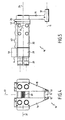
- FIGS. 2 and 3 are end views of the pliers of FIGS. 2 and 3; which shows two arms going through at its lower end Clamping jaws or jaws for gripping a wire section Are completed.
- Figure 5 is a side view of the pliers of Figures 2 to 4; a charge amplifier is also shown in this figure, the one with the force sensor through a conductor wire connected is.
- FIG. 6 is a graph showing changes in insertion force (plotted on the ordinate axis) depending from that measured along an insertion axis relative position (plotted on the abscissa axis) the end of the wire section (or one on top of one End crimped cable lug) with respect to a socket of a connector.
- FIG. 7 is a partial schematic view of a pair of pliers similar to that of FIGS. 2 to 5, the attachment of two Rings made of a piezoelectric ceramic material between the parts of one arm of the pliers.
- Fig. 8 is a circuit diagram showing the main components of the Means for measuring force by processing signals illustrated by two pairs of piezoelectric Items are delivered in two corresponding movable arms of a pair of pliers such as those in 2 to 7 are shown, are integrated.
- the introducer is 1 specifically for the introduction of one on the End 3 of a wire section 4 (shown in part) crimped cable lug 2 in one of the sockets 5 one Connector 6 designed.
- the machine 1 comprises a connector carrier 7, the one for a (not shown) base vertical translatory movement 8 and a rotary Movement 9 movably mounted about an axis 10 is; axis 10 is to the longitudinal axes of the bushings parallel; the insertion of the cable lug 2 into a socket takes place through an introductory movement through translation along the longitudinal axis of this socket, such as the axis 11th
- the cable lug 2 and the end 3 during this introductory movement is essentially aligned held on this axis 11 by the jaws 12, 13, at the lower ends of the arms 14 and 15 of the insertion forceps 16, which clamps the end 3, are provided.
- the unit UC can have a memory (or a other media) included in the for each type of Sockets / cable lug pairs multiple data in the form of Tables or graphs such as that of Fig. 6 entered are the (reference) nominal values for the force or Ranges of force ratings that correspond to the Force measurements compared during an insertion cycle become; these nominal force values can be measured by measuring the Force from the sensor integrated in the pliers is carried out by learning during preparatory Cycles that run under conditions that the represent actual introductory conditions become.
- FIGS. 3 and 7 contains each of the two movable units for crimping the Wire except the arm 14, 15 and the sliding part 28, 29 a force sensor 34 which is between the arm and the sliding part is inserted and clamped.
- Each sensor 34 comprises two completely identical annular ones Elements 35 made of a ceramic material on zirconate and Lead titanate base; on each of the two flat annular surfaces of each element 35 an electrode is formed which connects the positive pole or correspond to the negative pole of the polarized element.
- Each sensor also includes two rectangular plates 36, 37, which are substantially the same; every plate rests on two coplanar electrodes that rest on the corresponding annular surfaces of the two elements 35 are provided; the records are at least partly made of an electrically insulating material manufactured, further on the inner surface 38, 39 each Plate 36, 37 an electrically conductive coating provided to form an equipotential surface which connects the electrodes of the elements on which are located support these equipotential surfaces; every record - and their equipotential surface - can in particular in shape a printed circuit.
- Each equipotential surface is connected to a connection 40 or 41 of a connection carrier 42 of the sensor 34 connected; on Coaxial cable 43 connects these connections to the inputs of a charge amplifier 44 which is connected to section 21 the body 20 of the pliers 16 is attached (Fig. 5).
- Each sensor 34 also includes an intermediate plate 50 (not shown in Fig. 7), penetrated by two openings through which the disks extend, whereby this plate forms a housing with the plates 36, 37, that includes the two sensitive elements; the Plates 36 and 37 are each of two openings 51 interspersed, the center distance of that of the two disks 35 corresponds to, while each part 14, 15 of two openings 52 is interspersed by the same center distance are separated, and each part 28, 29 two threaded bores 53, which is also at the same center distance are separated.
- each screw rests on an arm 14 or 15 from; each screw extends through one of the openings 52, through an opening 51 of each plate 36, 37 and through the central opening of an element 35; every screw is engaged in a bore 53; by tightening of the screws, each element 35 is sandwiched between the plates 36, 37 arranged and between them Surfaces 38 and 39 are clamped in, the plates also clamped between parts 14 and 28 (or 15 and 29) are.
- Each module 44 includes an amplifier 45 and a capacitance 46 which is between the negative input of the Amplifier 45 and its output is connected; the negative input is with a negative terminal 41 of the Sensor connected while the positive input to the positive connection 40 of the sensor and connected to ground is; this circuit arrangement forms an integrator, which provides a voltage at the output which is cumulative Changes in the charge of the two sensitive elements 35 between the plates 36, 37 to each other are arranged opposite, is proportional.
- This voltage is applied to the unit UC via a cable 47 delivered.
- the operation of the device is as follows: The Approximation of the cable lug 2 with respect to a socket 5 done by the actuator M; due to the accumulated Mass of the cable lug 2, the end 3 of the wire and Part 14 or 15 of the arm suspended from each sensor is an inertial force resulting from the acceleration 57, hung on the center of gravity of the on the sensor System is exercised, which is generally in near the center of gravity 56 (FIG. 7) of the arm 14 (or 15) located; if this force on the outside environment of the part of the plane of Fig. 7 which is between the extends both axes 55 of the sensitive elements, is exercised, these are claimed differentially; element 35, which is located on the left in FIG.
Landscapes
- Engineering & Computer Science (AREA)
- Manufacturing & Machinery (AREA)
- Manipulator (AREA)
Abstract
Description
- eine Zange oder eine Handhabungsvorrichtung gemäß der Erfindung,
- einen Verbinder-Träger,
- wenigstens einen Aktuator für die Verlagerung der Zange (Handhabungsvorrichtung) zu einem am Verbinder-Träger befestigen Verbinder,
- Mittel zum Steuern der Verlagerung der Zange (Handhabungsvorrichtung) durch den Aktuator in Abhängigkeit von einem Kraftmeßsignal, das von dem in die Zange (Handhabungsvorrichtung) integrierten Sensor geliefert wird.
Claims (13)
- Handhabungsvorrichtung (16) für einen Draht (3, 4), die einen Körper (20) und ein Drahthalteorgan (14, 15, 28, 29) umfaßt, das in bezug auf den Körper beweglich angebracht ist, dadurch gekennzeichnet, daß das Drahthalteorgan einen Sensor (34) aufweist, der für eine durch dieses Organ ausgeübte Kraft empfindlich ist.
- Zange (16) zum Einführen eines Endes (2, 3) einer Drahtleitung (4) in eine Buchse (5) eines Verbinders (6), wobei die Zange (16) einen Körper (20) und einen Arm (14, 15, 28, 29), der mit einer Spannbacke (12, 13) zum Spannen des Drahts ausgerüstet ist, aufweist, wobei der Arm in bezug auf den Körper beweglich angebracht ist, dadurch gekennzeichnet, daß der Arm einen piezoelektrischen Sensor (34) zum Messen einer Einführungskraft aufweist.
- Zange oder Handhabungsvorrichtung nach Anspruch 1 oder 2, in der der Sensor zwei dünne Teile (35) aus einem polarisierten keramischen Werkstoff umfaßt, die zwischen zwei Abschnitten des Arms oder Halteorgans eingespannt angebracht sind.
- Zange oder Handhabungsvorrichtung nach Anspruch 3, in der die dünnen Teile zwischen diesen Abschnitten zueinander entgegengesetzt angeordnet sind, um eine entgegengesetzte Montage zu bilden.
- Zange oder Handhabungsvorrichtung nach einem der Ansprüche 1 bis 4, in der der Sensor (34) für ein Drehmoment - oder Kräftemoment -, das sich aus der Ausübung einer Kraft (61) ergibt, die in der Nähe eines longitudinalen Endes des Arms oder des Halteorgans (14, 15) ausgeübt wird, empfindlich ist.
- Zange oder Handhabungsvorrichtung nach einem der Ansprüche 1 bis 5, die einen an den Sensor angeschlossenen Verstärker (44) umfaßt, der mit dem Körper fest verbunden ist.
- Zange oder Handhabungsvorrichtung nach einem der Ansprüche 3 bis 6, in der jedem dünnen Teil wenigstens ein langgestrecktes Verbindungsorgan (54) - etwa eine Schraube, die durch eine Öffnung in einem dünnen Teil in Form eines Rings verläuft - zugeordnet ist, das eine Druckbeaufschlagung des dünnen Teils sicherstellt und eine Feder bildet, die der Ausdehnung des dünnen Teils entgegenwirkt.
- Zange oder Handhabungsvorrichtung nach einem der Ansprüche 1 bis 7, die zwei Arme oder Draht-Halteorgane, die jeweils mit einem Kraftsensor ausgerüstet sind, und Mittel (70) für die Summation von von den beiden Sensoren gelieferten Signale umfaßt.
- Zange oder Handhabungsvorrichtung nach einem der Ansprüche 1 bis 8, die umfaßt:einen Körper (20), der einen Stellzylinder (22, 23) enthält,zwei Draht-Halteorgane, die so angebracht sind, daß sie unter der Wirkung des Stellzylinders und eines Rückstellmittels (30) in bezug auf den Körper zwischen einer geöffneten Position und einer geschlossenen Position gleiten, wobei jedes dieser Gleitorgane umfaßt:einen Arm (14, 15), der eine Spannbacke (12, 13) aufweist,einen Sensor (34), der zwei empfindliche Elemente (35) aus Keramik enthält, die polarisiert sind und zwischen Flächen (38, 39) von Teilen (36, 37) komprimiert sind, die Äquipotentialflächen-Verbindungsmittel enthalten, die mit einem Anschluß (40, 41) einer Anschlußanordnung (42) verbunden sind,langgestreckte Organe (54) für eine elastische Verbindung, die sich längs Achsen (55) erstrecken, die zur Achse (11) der Spannbacken (12, 13) im wesentlichen parallel sind, und dazu dienen, die empfindlichen Elemente (35) zu komprimieren.
- Maschine (1) zum Einführen eines Kabelschuhs (2) und/oder eines Endes (3) eines Drahtleitungs-Teilstücks (4) in eine Buchse (5) einer Komponente (6), wobei die Maschine (1) umfaßt:eine Zange oder Handhabungsvorrichtung (16) nach einem der Ansprüche 1 bis 9,einen Verbinder-Träger (7),einen Aktuator (M) zum Verlagern der Zange (Handhabungsvorrichtung) zu einem an dem Träger (7) befestigten Verbinder (6) undMittel (44, C, UC) zum Steuern der Verlagerung der Zange durch den Aktuator in Abhängigkeit von einem Kraftmeßsignal, das von dem in die Zange (oder Handhabungsvorrichtung) integrierten Sensor (34) geliefert wird.
- Verwendung eines dynamischen Kraftsensors (34) zum Messen und Kontrollieren in Echtzeit der Kraft zum Einführen eines Kabelschuhs (2) oder eines Endes (3) eines Drahts (4) in eine Buchse (5) eines Verbinders (6).
- Verfahren zum Einführen eines Kabelschuhs (2) und/oder eines Endes (3) eines Drahts (4) in eine Buchse (5) eines Verbinders (6) mit Hilfe einer Zange oder einer Handhabungsvorrichtung, bei dem in Echtzeit die von einem Abschnitt wenigstens eines Arms oder Halteorgans für den Kabelschuh oder den Draht übertragene Kraft gemessen und kontrolliert wird, wobei dann, wenn festgestellt wird, daß das Meßergebnis von einem Referenzwert um einen Wert abweicht, der außerhalb eines vorgegebenen maximalen Abweichungsbereichs liegt, das Anhalten eines Organs (M) für die Verlagerung der Zange oder der Handhabungsvorrichtung befohlen wird, um die Einführungsprozedur anzuhalten, was ermöglicht, eine Beschädigung des Verbinders und/oder des Kabelschuhs zu vermeiden.
- Verfahren nach Anspruch 12, bei dem ein Sensor (34) aus einem piezoelektrischen Keramikwerkstoff verwendet wird, dessen Ausgang mit einem Ladungsverstärker (44) verbunden ist, wobei der Eingang und/oder der Ausgang des Verstärkers vor jeder Einführungsoperation auf null zurückgesetzt wird, um die Restladungen zu beseitigen, die sich aus der vorhergehenden Einführungsoperation und/oder aus einer oder mehreren Greifbewegungen und/oder aus der Annäherung des Kabelschuhs oder des Drahtendes ergeben könnten.
Priority Applications (1)
| Application Number | Priority Date | Filing Date | Title |
|---|---|---|---|
| EP20020023328 EP1317031B1 (de) | 2001-10-31 | 2002-10-18 | Handhabungsvorrichtung für Drahtleitung, Einführungsmaschine und Einführungsverfahren mit einer solchen Handhabungsvorrichtung |
Applications Claiming Priority (3)
| Application Number | Priority Date | Filing Date | Title |
|---|---|---|---|
| EP01811057 | 2001-10-31 | ||
| EP01811057 | 2001-10-31 | ||
| EP20020023328 EP1317031B1 (de) | 2001-10-31 | 2002-10-18 | Handhabungsvorrichtung für Drahtleitung, Einführungsmaschine und Einführungsverfahren mit einer solchen Handhabungsvorrichtung |
Publications (2)
| Publication Number | Publication Date |
|---|---|
| EP1317031A1 true EP1317031A1 (de) | 2003-06-04 |
| EP1317031B1 EP1317031B1 (de) | 2011-01-05 |
Family
ID=26077432
Family Applications (1)
| Application Number | Title | Priority Date | Filing Date |
|---|---|---|---|
| EP20020023328 Expired - Lifetime EP1317031B1 (de) | 2001-10-31 | 2002-10-18 | Handhabungsvorrichtung für Drahtleitung, Einführungsmaschine und Einführungsverfahren mit einer solchen Handhabungsvorrichtung |
Country Status (1)
| Country | Link |
|---|---|
| EP (1) | EP1317031B1 (de) |
Cited By (5)
| Publication number | Priority date | Publication date | Assignee | Title |
|---|---|---|---|---|
| CN108406251A (zh) * | 2018-05-09 | 2018-08-17 | 立讯精密工业(滁州)有限公司 | 套管组装设备 |
| CN109317778A (zh) * | 2018-11-01 | 2019-02-12 | 深圳市德沃先进自动化有限公司 | 一种基于焊线设备的高速夹线装置 |
| US10723584B2 (en) | 2016-10-03 | 2020-07-28 | Komax Holding Ag | Method and device for aligning prefabricated cable ends of a cable harness in correct rotational position |
| US10804668B2 (en) | 2016-10-03 | 2020-10-13 | Komax Holding Ag | Device for assembling a plug housing |
| CN117895306A (zh) * | 2024-03-13 | 2024-04-16 | 潍坊智新电子股份有限公司 | 一种线束自动穿壳设备 |
Families Citing this family (2)
| Publication number | Priority date | Publication date | Assignee | Title |
|---|---|---|---|---|
| EP2958201A1 (de) | 2014-06-16 | 2015-12-23 | Delphi Technologies, Inc. | Vorrichtung und Verfahren zum automatischen Bestücken eines Steckergehäuses |
| CN111451741A (zh) * | 2020-04-10 | 2020-07-28 | 重庆泰美自动化科技有限公司 | 自动化理线机控制系统 |
Citations (6)
| Publication number | Priority date | Publication date | Assignee | Title |
|---|---|---|---|---|
| US4990815A (en) * | 1989-07-11 | 1991-02-05 | Lindner Douglas K | Robot gripper control system using PYDF piezoelectric sensors |
| FR2669156A1 (fr) * | 1990-11-14 | 1992-05-15 | Entreprise Ind Sa L | Procede et dispositif de guidage pour l'introduction automatique d'une piece male dans une piece femelle. |
| US5157830A (en) * | 1988-07-01 | 1992-10-27 | Ttc Technology Trading Company | Method for automatically connecting electric conductors with contact parts to connector shells |
| US5222778A (en) * | 1990-11-28 | 1993-06-29 | Hofmann Maschinenbau Gmbh | Workpiece gripping apparatus |
| FR2696215A1 (fr) * | 1992-09-25 | 1994-04-01 | Bras Serge | Elément d'assemblage et procédé et machine d'assemblage. |
| US6098275A (en) * | 1996-10-23 | 2000-08-08 | Framatome Connectors International | Method for inserting an electrical contact pin with an compliant attachment zone into a hole in a printed circuit board |
-
2002
- 2002-10-18 EP EP20020023328 patent/EP1317031B1/de not_active Expired - Lifetime
Patent Citations (6)
| Publication number | Priority date | Publication date | Assignee | Title |
|---|---|---|---|---|
| US5157830A (en) * | 1988-07-01 | 1992-10-27 | Ttc Technology Trading Company | Method for automatically connecting electric conductors with contact parts to connector shells |
| US4990815A (en) * | 1989-07-11 | 1991-02-05 | Lindner Douglas K | Robot gripper control system using PYDF piezoelectric sensors |
| FR2669156A1 (fr) * | 1990-11-14 | 1992-05-15 | Entreprise Ind Sa L | Procede et dispositif de guidage pour l'introduction automatique d'une piece male dans une piece femelle. |
| US5222778A (en) * | 1990-11-28 | 1993-06-29 | Hofmann Maschinenbau Gmbh | Workpiece gripping apparatus |
| FR2696215A1 (fr) * | 1992-09-25 | 1994-04-01 | Bras Serge | Elément d'assemblage et procédé et machine d'assemblage. |
| US6098275A (en) * | 1996-10-23 | 2000-08-08 | Framatome Connectors International | Method for inserting an electrical contact pin with an compliant attachment zone into a hole in a printed circuit board |
Cited By (6)
| Publication number | Priority date | Publication date | Assignee | Title |
|---|---|---|---|---|
| US10723584B2 (en) | 2016-10-03 | 2020-07-28 | Komax Holding Ag | Method and device for aligning prefabricated cable ends of a cable harness in correct rotational position |
| US10804668B2 (en) | 2016-10-03 | 2020-10-13 | Komax Holding Ag | Device for assembling a plug housing |
| CN108406251A (zh) * | 2018-05-09 | 2018-08-17 | 立讯精密工业(滁州)有限公司 | 套管组装设备 |
| CN109317778A (zh) * | 2018-11-01 | 2019-02-12 | 深圳市德沃先进自动化有限公司 | 一种基于焊线设备的高速夹线装置 |
| CN117895306A (zh) * | 2024-03-13 | 2024-04-16 | 潍坊智新电子股份有限公司 | 一种线束自动穿壳设备 |
| CN117895306B (zh) * | 2024-03-13 | 2024-05-10 | 潍坊智新电子股份有限公司 | 一种线束自动穿壳设备 |
Also Published As
| Publication number | Publication date |
|---|---|
| EP1317031B1 (de) | 2011-01-05 |
Similar Documents
| Publication | Publication Date | Title |
|---|---|---|
| DE3590038C2 (de) | ||
| DE69617148T2 (de) | Fühlerprobe | |
| EP0237598B1 (de) | Piezoresistives Kraftmesselement sowie dessen Verwendung zur Ermittlung von auf ein Bauteil einwirkenden Kräften | |
| DE102008042942B4 (de) | Gassensor und Verfahren zum Herstellen dessleben | |
| DE9214356U1 (de) | Testsockel zur Aufnahme der Anschlußstifte elektrischer und/oder elektronischer Vorrichtungen ohne Einsetzdruck | |
| DE10297410B4 (de) | Rollenkontakt mit leitenden Bürsten | |
| EP3532855A1 (de) | Batteriegreifer | |
| DE69504826T2 (de) | Vorrichtung und verfahren zur befestigung eines sensors an einem gegenstand | |
| EP1317031B1 (de) | Handhabungsvorrichtung für Drahtleitung, Einführungsmaschine und Einführungsverfahren mit einer solchen Handhabungsvorrichtung | |
| WO1999014583A1 (de) | Gassensor | |
| EP0136437A1 (de) | Mehrkomponentenkraft- und -momentenmesskörper mit Dehnungsmessstreifen | |
| EP0829711A2 (de) | Druckschalteinrichtung, insbesondere für die Kraftfahrzeugtechnik | |
| DE3343274C2 (de) | ||
| DE102021203858A1 (de) | Sensorik zur Lasterfassung an Metallkissen | |
| DE102016226282B4 (de) | Messelement, Messsystem und Verfahren zur Bereitstellung eines Messelements zur Messung von Kräften | |
| DE4013434A1 (de) | Elektrodensystem | |
| EP0418766A1 (de) | DruckÀ¼bertragungselement für eine Anschlussklemme | |
| DE2112107C3 (de) | Vorrichtung und Verfahren zum Prüfen von Kontaktfedern | |
| DE102022130427B3 (de) | Vorrichtung zum Halten, Lagern und/oder Führen eines stabförmigen Elements aus einer magnetischen Formgedächtnislegierung | |
| DE102019119733A1 (de) | Drucksensor | |
| DD259707A1 (de) | Vorrichtung zum loesbaren verbinden elektrischer leitungen | |
| DE102011110897A1 (de) | Verfahren zur Einstellung einer Zündspannung einer Schaltfunkenstrecke, gasgefüllte Schaltfunkenstrecke und Justagevorrichtung zum Einstellen einer Zündspannung | |
| WO1999053283A1 (de) | Vorrichtung zum abfragen mehrerer sensorelemente in matrix-verschaltung | |
| DE102018200684A1 (de) | Montageanordnung | |
| EP4289543B1 (de) | Vorrichtung zur messung der schweisskraft und zur erfassung der elektrischen schweissspannung während eines schweissvorgangs einer widerstandschweisseinrichtung |
Legal Events
| Date | Code | Title | Description |
|---|---|---|---|
| PUAI | Public reference made under article 153(3) epc to a published international application that has entered the european phase |
Free format text: ORIGINAL CODE: 0009012 |
|
| AK | Designated contracting states |
Designated state(s): AT BE BG CH CY CZ DE DK EE ES FI FR GB GR IE IT LI LU MC NL PT SE SK TR |
|
| AX | Request for extension of the european patent |
Extension state: AL LT LV MK RO SI |
|
| 17P | Request for examination filed |
Effective date: 20031114 |
|
| AKX | Designation fees paid |
Designated state(s): CH DE FR GB IT LI |
|
| 17Q | First examination report despatched |
Effective date: 20080617 |
|
| GRAP | Despatch of communication of intention to grant a patent |
Free format text: ORIGINAL CODE: EPIDOSNIGR1 |
|
| GRAS | Grant fee paid |
Free format text: ORIGINAL CODE: EPIDOSNIGR3 |
|
| GRAA | (expected) grant |
Free format text: ORIGINAL CODE: 0009210 |
|
| AK | Designated contracting states |
Kind code of ref document: B1 Designated state(s): CH DE FR GB IT LI |
|
| REG | Reference to a national code |
Ref country code: GB Ref legal event code: FG4D Free format text: NOT ENGLISH |
|
| REG | Reference to a national code |
Ref country code: CH Ref legal event code: EP |
|
| REG | Reference to a national code |
Ref country code: CH Ref legal event code: NV Representative=s name: INVENTIO AG |
|
| REF | Corresponds to: |
Ref document number: 50214847 Country of ref document: DE Date of ref document: 20110217 Kind code of ref document: P |
|
| REG | Reference to a national code |
Ref country code: DE Ref legal event code: R096 Ref document number: 50214847 Country of ref document: DE Effective date: 20110217 |
|
| PLBE | No opposition filed within time limit |
Free format text: ORIGINAL CODE: 0009261 |
|
| STAA | Information on the status of an ep patent application or granted ep patent |
Free format text: STATUS: NO OPPOSITION FILED WITHIN TIME LIMIT |
|
| 26N | No opposition filed |
Effective date: 20111006 |
|
| REG | Reference to a national code |
Ref country code: DE Ref legal event code: R097 Ref document number: 50214847 Country of ref document: DE Effective date: 20111006 |
|
| GBPC | Gb: european patent ceased through non-payment of renewal fee |
Effective date: 20111018 |
|
| PG25 | Lapsed in a contracting state [announced via postgrant information from national office to epo] |
Ref country code: GB Free format text: LAPSE BECAUSE OF NON-PAYMENT OF DUE FEES Effective date: 20111018 |
|
| REG | Reference to a national code |
Ref country code: FR Ref legal event code: PLFP Year of fee payment: 14 |
|
| REG | Reference to a national code |
Ref country code: FR Ref legal event code: PLFP Year of fee payment: 15 |
|
| REG | Reference to a national code |
Ref country code: FR Ref legal event code: PLFP Year of fee payment: 16 |
|
| REG | Reference to a national code |
Ref country code: FR Ref legal event code: PLFP Year of fee payment: 17 |
|
| PGFP | Annual fee paid to national office [announced via postgrant information from national office to epo] |
Ref country code: DE Payment date: 20211027 Year of fee payment: 20 |
|
| PGFP | Annual fee paid to national office [announced via postgrant information from national office to epo] |
Ref country code: IT Payment date: 20211020 Year of fee payment: 20 Ref country code: FR Payment date: 20211027 Year of fee payment: 20 Ref country code: CH Payment date: 20211022 Year of fee payment: 20 |
|
| REG | Reference to a national code |
Ref country code: DE Ref legal event code: R071 Ref document number: 50214847 Country of ref document: DE |
|
| REG | Reference to a national code |
Ref country code: CH Ref legal event code: PL |