EP1316828A1 - Hermetisch dichte Durchführung für eine Lichtleitfaser und Verfahren zu deren Herstellung - Google Patents
Hermetisch dichte Durchführung für eine Lichtleitfaser und Verfahren zu deren Herstellung Download PDFInfo
- Publication number
- EP1316828A1 EP1316828A1 EP02024730A EP02024730A EP1316828A1 EP 1316828 A1 EP1316828 A1 EP 1316828A1 EP 02024730 A EP02024730 A EP 02024730A EP 02024730 A EP02024730 A EP 02024730A EP 1316828 A1 EP1316828 A1 EP 1316828A1
- Authority
- EP
- European Patent Office
- Prior art keywords
- glass
- bushing
- optical fiber
- glass solder
- hermetic
- Prior art date
- Legal status (The legal status is an assumption and is not a legal conclusion. Google has not performed a legal analysis and makes no representation as to the accuracy of the status listed.)
- Granted
Links
Images


Classifications
-
- G—PHYSICS
- G02—OPTICS
- G02B—OPTICAL ELEMENTS, SYSTEMS OR APPARATUS
- G02B6/00—Light guides; Structural details of arrangements comprising light guides and other optical elements, e.g. couplings
- G02B6/24—Coupling light guides
- G02B6/42—Coupling light guides with opto-electronic elements
- G02B6/4201—Packages, e.g. shape, construction, internal or external details
- G02B6/4248—Feed-through connections for the hermetical passage of fibres through a package wall
-
- G—PHYSICS
- G02—OPTICS
- G02B—OPTICAL ELEMENTS, SYSTEMS OR APPARATUS
- G02B6/00—Light guides; Structural details of arrangements comprising light guides and other optical elements, e.g. couplings
- G02B6/44—Mechanical structures for providing tensile strength and external protection for fibres, e.g. optical transmission cables
- G02B6/4439—Auxiliary devices
- G02B6/4471—Terminating devices ; Cable clamps
- G02B6/44775—Cable seals e.g. feed-through
-
- G—PHYSICS
- G02—OPTICS
- G02B—OPTICAL ELEMENTS, SYSTEMS OR APPARATUS
- G02B6/00—Light guides; Structural details of arrangements comprising light guides and other optical elements, e.g. couplings
- G02B6/24—Coupling light guides
- G02B6/36—Mechanical coupling means
- G02B6/38—Mechanical coupling means having fibre to fibre mating means
- G02B6/3807—Dismountable connectors, i.e. comprising plugs
- G02B6/3833—Details of mounting fibres in ferrules; Assembly methods; Manufacture
- G02B6/3855—Details of mounting fibres in ferrules; Assembly methods; Manufacture characterised by the method of anchoring or fixing the fibre within the ferrule
-
- G—PHYSICS
- G02—OPTICS
- G02B—OPTICAL ELEMENTS, SYSTEMS OR APPARATUS
- G02B6/00—Light guides; Structural details of arrangements comprising light guides and other optical elements, e.g. couplings
- G02B6/44—Mechanical structures for providing tensile strength and external protection for fibres, e.g. optical transmission cables
- G02B6/4401—Optical cables
- G02B6/4415—Cables for special applications
- G02B6/4427—Pressure resistant cables, e.g. undersea cables
- G02B6/4428—Penetrator systems in pressure-resistant devices
Definitions
- the invention relates to a method for hermetic glazing an optical fiber in a metallic bushing sleeve by means of a Glass solder.
- the invention further relates to one made by this method hermetic glazing.
- optical fibers for data transmission, i.e. Fiber optic cables that consist of a bundle of individual optical fibers, including optical ones Called glass fibers exist.
- the optical fibers have one Glass core, which is surrounded by a light-tight coat.
- the exposed optical waveguide is metallized and soldered to the wall in a metal-tight manner.
- the metallization of the optical fiber made of glass is complex and can easily be flawed. Bending protection for the part of the optical waveguide going outward is not possible in a simple manner.
- EP-A-0 105 198 describes a pressure-tight and gas-tight Optical fiber bushing described, in which an optical fiber without an enveloping protective layer by means of a low melting glass in a bushing is melted and at both ends in a connector part opens. To carry out the optical fiber So two connectors provided on the output and input side, with the Disadvantage of inevitable when connecting optical fibers occurring coupling losses.
- EP 0 274 222 also shows a bushing with a metal sleeve in which the optical fiber is attached by means of glass soldering.
- the invention is therefore based on the object, both a method for Hermetic injection of an optical fiber into a metal bushing to create a permanent hermetic implementation and is also relatively easy to implement in terms of process technology, as well as one corresponding permanent hermetic, easy to implement glazing provide.
- the solution is successful the task according to the invention in that the bushing from a metallic material formed by an Invar alloy and the glass solder from a low-melting composite glass solder with the Material of the bushing adapted to thermal expansion in the form of prefabricated semi-cylindrical compacts, between which the Optical fiber stripped is embedded.
- the measures according to the invention succeed in terms of process engineering relatively easy way to create a permanent, hermetic glazing.
- Fig. 1 shows a longitudinal section of the structure of a preferred embodiment of an assembled according to the invention
- the metallic bushing sleeve itself is known with soldering technology Methods attached in an opening in the wall (not shown), being the wall preferably also made of the same material as that Bushing is made so that there are no mechanical stresses different coefficients of thermal expansion occur that the could endanger the durability of the hermetic seal.
- FIG. 2 shows the components involved in an exploded view the implementation or melting of Fig. 1, each in separate Figures 3 - 5 are shown in more detail.
- the hermetic bushing according to the invention is therefore generally based on a glass / metal bushing.
- Glass / metal feedthroughs are generally understood in electronics and electrical engineering as vacuum-tight fusing of glasses with metals for the insulated passage of electrical conductors in hermetically encapsulated housings.
- a preformed sintered glass part is melted into an outer metal part and in turn one or more metallic inner conductors are melted into this.
- Fig. 5 shows the structure of an optical fiber 1, as they are typically used for modern fiber optic cables.
- This optical fiber 1, also called optical waveguide, has a glass fiber 2 with a typical outer diameter of 125 ⁇ m and a quartz glass core with a diameter of 50 ⁇ m.
- An inner plastic protective layer 3 adheres firmly to the glass fiber 2.
- the optical waveguide 1 also has an outer, loose plastic sheathing 4, which forms an outer protective cover.
- FIG. 1 shows
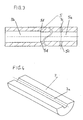
- This bushing sleeve 5 which is shown in more detail in section in Fig. 3, consists of a material with a very low thermal Expansion coefficient ( ⁇ 5 ppm / K). Such a material is especially the material VACON from the company vacuum melt. This The material is a special melting alloy for tempered glass and ceramics controlled thermal expansion with linear Thermal expansion coefficient of almost zero. He sits down chemical in% by weight from Ni ( ⁇ 29%), Co (17 - 23%), Mn (0.25%), Si ( ⁇ 0.2 &), C ⁇ 0.02% and Fe (rest) together and is among the Material numbers 1.3981 and 1.3982 registered.
- Ni-Co-Fe alloys are also used by offered to other companies, e.g. by Westinghouse Electric Corporation at the brand "KOVAR".
- Other trade names are Therlo, Rodar, Nicoseal, Sealvac-A, Nilo K, Dilver P. They are in the relevant company data sheets and material manuals, e.g. in the "Handbook of Materials and Techniques for Vacuum Devices "by Walter H. Kohl, published by Reinhold Publishing Corporation, 430 Park Avenue, New York, N.Y. 10022.
- the low thermal expansion of these alloys is due to the exceptional expansion properties that can be seen in the systems Fe-Ni-Co, Fe-Ni-Cr and Fe-Ni.
- the small thermal expansion of this Alloys are created by the Invar effect (positive vacuum magnetostriction) caused, which affects up to the Curie point. It is therefore also the Alloy Ni-Fe 42 can be used.
- the housing also consists of an electro-optical arrangement, through the wall of the sleeve 5 is made of one of these alloys, so that thermomechanical tensions between the sleeve and Housing walls are avoided.
- the bushing 5 is for better solderability in the Gold-plated case wall. It has two axial sections 5 a, 5 b with different inner diameters. In the entry-side section 5 a with smaller diameter than in the outlet-side section 5 b, is Optical fiber 1 to be carried out or melted in initially completely with all components included. In the further course is the outer one loose plastic sheathing 4, then also the firmly adhering one Plastic layer 3, removed so that about half of the 1st section 5th a and completely over the 2nd section 5 b only the "stripped" or "Decoated” glass fiber 2 is added.
- the bushing 5 also has holes 5 c for filling the first Sections 5 a with, for example, epoxy resin 6 as strain relief for the Glass fiber.
- the second section 5 b are two half-shells 7 from one to the Material of the bushing 5 adapted composite glass solder in the form picked up by semi-cylindrical glass solder compacts.
- the shoulder 5 d at the transition between the two sections 5 a, 5 b of the sleeve is used for Position the two glass solder half shells in the bushing.
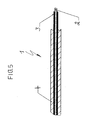
- One of these half-shell glass solder compacts 7 is shown in more detail in FIG. 4.
- the half-shell compacts 7 each have a central cross section semicircular groove 7 a, in which the decoated glass fiber 2 is embedded. These half-shell glass solder compacts are used for "actual" melting the optical fiber in the metallic bushing sleeve 5, i.e. educate the Solder glass melting as a hermetic bond of the half-shell with glass fiber and sleeve.
- the half-shell shaped glass solder compacts 7 consist of a low melting composite glass solder with the material of the Bushing adapted to thermal expansion. Your outside diameter determined by the inner diameter of the sleeve 5 in section 5 b, and their inside diameter, i.e. the diameter of the groove 7 a is determined by the diameter of the glass fiber 2. The maximum length is on the press limited to about three times the outer diameter.
- glass solder compacts are manufactured according to the pressing / sintering technology in order to be used in electronics / electrical engineering as molded glass parts for the production of hermetic melts.
- the complex shapes and narrow tolerances required for such applications cannot be produced, or at least not economically, with the hot-forming processes which are otherwise customary in glass production.
- the route via glass powder, glass granules and press-sintering technology allows a much more efficient production with high dimensional accuracy.
- Glass ground into powder is not directly suitable for dry pressing.
- binder By adding binder, the inherently non-plastic glass powder is brought into a pourable and compressible form.
- This so-called glass pressed granulate is produced by adding fine-grained glass powder (d 50 approx. 10 - 20 ⁇ m) with organic binders (and plasticizers) in a spray drying process.
- the glass powder and optionally a color pigment and / or stretch-reducing inert fillers in an aqueous binder emulsion suspended This spray slip is then passed through a nozzle into the chamber sprayed into the spray dryer.
- the resulting droplets dry in Counter current of the drying gas to granules.
- the grain distribution of the Press granules obtained are between 80 microns and 350 microns.
- the pressed granulate is then dried in uniaxial presses brought into the desired shape.
- the actual press tool consists of a press die and upper and lower punches. Depending on the complexity of the The stamps can also be compacted several times.
- the The mold is filled with granules using a filling shoe.
- the actual compacting is then carried out by a controlled one Downward movement of the upper punch (one-sided pressing) or by simultaneous Movement of the upper and lower punches against each other (two-sided pressing).
- the compression ratio of the filling depth with granulate to the height of the Green compact after pressing
- the ratio of height (dimension in the pressing direction) to The diameter of the glass compact cannot be arbitrarily large.
- the limit for Solid body or parts with not too small wall thickness is approx. 3: 1.
- the green compacts are debound in special ovens (usually continuous ovens) after sintering and sintered to their final dimensions.
- special ovens usually continuous ovens
- the process is carried out according to a special temperature / time curve in which the green compacts are first heated to the binder burnout temperature at a moderate heating rate. After the binder has completely burned out, the compacts are further heated to a higher temperature at which the actual sintering takes place into compact glass parts. This temperature corresponds to a temperature at which the corresponding glass has a viscosity of approximately 10 8 dPas and -10 9 dPas.
- the sintering shrinkage (difference in dimensions between green glass compact and sintered glass part) is approx. 14%.
- half-shells to press, which halved the shape of such, along its longitudinal axis Have compacts.
- Two of these half shells 7 can then, as in the Drawings shown to assemble the stripped glass fiber 2 and - like with a regular compact with an inner hole - in a tubular sleeve or Drilled hole in a hybrid housing and be fused.
- This new technology also allows glazing at any point of a fiber strand and not just terminally as in the prior art.
- the coating of the glass fiber can be removed at any point and can be assembled with the two half-shells and the sleeve.
- the actual thermal fusion can then e.g. with the help of a electrically heated filament, but also inductive, by means of focused IR radiation or in specially designed ovens that use a local Ensure heat input that is concentrated on the melting area and so thermal damage to the protective layer or outer Wrapping the glass fiber prevented.
- the half-shell shaped glass solder compacts 7, as already mentioned, consist of low-melting composite glass solder with thermal expansion adapted to the material of the bushing 5.
- Composite glass solders of this type for producing rigid, generally electrically insulating and hermetic connections between materials such as glass, ceramic or metal are described in particular in Product Information No. 4823/1 d by the applicant.
- Composite glass solders are glass solders whose thermal expansion is modified by inert fillers with small or even negative thermal expansion.
- the composite glass solders also allow a lowering of the soldering temperature.
- a low-melting, stable glass solder with the Schott glass number G 017-339 listed in the above product information has proven to be suitable for the production of the half-shell shaped glass solder compacts.
- This composite glass solder consists of a lead borate base glass with an inert, strain-reducing filler ⁇ - eucryptite with a linear thermal expansion coefficient according to DIN 52328 ⁇ 20 - 250 of 4.7 • 10 -6 K -1 and a transformation temperature according to DIN 52 324 of 325 ° C. It is typically suitable for materials with a thermal expansion of 5-6 ppm / K. In principle, however, other fillers can also be used.
- Phosphate glass solders with suitable fillers can also be used be used. Also a composite glass solder with a modified lead titanate according to Schott glass number G 018 - 174 can be used. Important for a well-adapted glazing is only that the thermal expansion in the The range is 4.3 - 5 ppm / K and the processing (soldering) temperature below the Curie temperature of the material of the bushing 5 lies.
Landscapes
- Physics & Mathematics (AREA)
- General Physics & Mathematics (AREA)
- Optics & Photonics (AREA)
- Light Guides In General And Applications Therefor (AREA)
- Optical Couplings Of Light Guides (AREA)
- Glass Compositions (AREA)
- Mechanical Coupling Of Light Guides (AREA)
Abstract
Description
Das Metallisieren des aus Glas bestehenden Lichtwellenleiters ist aufwendig und kann leicht mit Fehlern behaftet sein. Ein Biegeschutz für den nach außen abgehenden Teil des Lichtwellenleiters ist nicht in einfacher Weise möglich.
Diese Verfahren, vor allem die Klebetechnik, erzeugen jedoch keinen dauerhaft hermetischen Verbund.
- Bereitstellen einer Durchführungs-Hülse aus einem metallischen Werkstoff, bestehend aus einer Invar-Legierung,
- Abmanteln der Lichtleitfaser von Schutzschichten unter Freilegung der Glasfaser,
- Bereitstellen von zwei Halbschalen in Form von halbzylinderförmigen Preßlingen aus einem niedrigschmelzenden Komposit-Glaslot mit an den Werkstoff der Durchführungs-Hülse angepaßter Wärmeausdehnung, die jeweils eine axiale Rille mit halbkreisförmigem, an den Durchmesser der freigelegten Glasfaser angepaßten Querschnitt aufweisen,
- Assemblieren der beiden Halbschalen unter Einbetten der freigelegten Glasfaser in die Rillen der Halbschalen,
- Verschmelzen der Halbschalen untereinander sowie mit der Glasfaser und der Durchführungs-Hülse durch lokalen Wärmeeintrag.
- Fig. 1
- in einer Längsschnitt-Darstellung eine Durchführungs-Hülse mit eingeglaster Lichtleitfaser, ausgebildet nach der Erfindung,
- Fig. 2
- in einer Explosions-Darstellung die an der Einglasung nach Fig. 1 beteiligten Komponenten,
- Fig. 3
- in einem Längsschnitt die Ausbildung der Durchführungs-Hülse mit ihren beiden axialen Abschnitten,
- Fig. 4
- ein vorgefertigter, halbzylinderförmiger Preßling aus einem niedrig schmelzenden Komposit-Glaslot mit einer axialen Rille, wobei zwei dieser Preßlinge in assemblierter Form gemäß Fig. 1 die abgemantelte Lichtleitfaser in der Rille umfassen, und
- Fig. 5
- den typischen Aufbau einer konventionellen Lichtleitfaser mit einem Glasfaser-Kern und einer Ummantelung bzw. Schutzschicht.
Unter Glas/Metall-Durchführungen versteht man generell in der Elektronik und Elektrotechnik vakuumdichte Verschmelzungen von Gläsern mit Metallen zur isolierten Durchführung von elektrischen Leitern in hermetisch gekapselte Gehäuse. Bei der typischen Glas/Metall-Durchführung werden in ein äußeres Metallteil ein vorgeformtes Sinterglasteil und in dieses wiederum ein oder mehrere metallische Innenleiter eingeschmolzen.
Diese Lichtleitfaser 1, auch Lichtwellenleiter genannt, weist eine Glasfaser 2 mit einem typischen Außendurchmesser von 125 µm und einem Quarzglaskern von 50 µm Durchmesser auf. An der Glasfaser 2 haftet eine innere Kunststoff-Schutzschicht 3 fest an.
Nachdem der Binder vollständig ausgebrannt ist, werden die Preßlinge weiter auf eine höhere Temperatur erhitzt, bei der die eigentliche Sinterung zu kompakten Glasteilen stattfindet. Diese Temperatur entspricht dabei einer Temperatur, bei der das entsprechende Glas eine Viskosität von etwa 108 dPas und -109 dPas aufweist.
Der Sinterschrumpf (Unterschied der Abmessungen zwischen Grünglas-Pressling und gesintertem Glasteil) liegt bei ca. 14 %.
Claims (13)
- Verfahren zum hermetischen Einglasen einer Lichtleitfaser in eine metallische Durchführungs-Hülse mittels eines Glaslotes, mit den Schritten:Bereitstellen einer Durchführungs-Hülse (5) aus einem metallischen Werkstoff, bestehend aus einer Invar-Legierung,Abmanteln der Lichtleitfaser (1) von Schutzschichten (3, 4) unter Freilegung der Glasfaser (2),Bereitstellen von zwei Halbschalen (7) in Form von halbzylinderförmigen Preßlingen aus einem niedrigschmelzenden Komposit-Glaslot mit an den Werkstoff der Durchführungs-Hülse (5) angepaßter Wärmeausdehnung, die jeweils eine axiale Rille (7 a) mit halbkreisförmigem, an den Durchmesser der freigelegten Glasfaser (2) angepaßten Querschnitt aufweisen,Assemblieren der beiden Halbschalen (7) unter Einbetten der freigelegten Glasfaser (2) in die Rillen der Halbschalen (7),Verschmelzen der Halbschalen (7) untereinander sowie mit der Glasfaser (2) und der Durchführungs-Hülse (5) durch lokalen Wärmeeintrag.
- Verfahren nach Anspruch 1, bei dem eine Durchführungs-Hülse (5) bereitgestellt wird, die zwei axiale Abschnitte (5 a, 5 b) mit unterschiedlichen Durchmessern aufweist, einen Abschnitt (5 b) zur Aufnahme der Halbschalen-Preßlinge (7) und einen vorgeschalteten Abschnitt (5 a) mit geringerem Durchmesser, in welchem die Lichtleitfaser nur in einem vorgegebenen Abschnitt abgemantelt ist, und der mit einem Kleber (6) ausgefüllt wird.
- Verfahren nach Anspruch 1 oder 2, daß als Werkstoff für die Durchführungs-Hülse (5) eine Invar-Legierung auf Ni-Co-Fe-Basis verwendet wird.
- Verfahren nach Anspruch 1 oder 2, bei dem als Werkstoff für die Durchführungs-Hülse eine Invar-Legierung auf Fe-Ni-Cr- oder Fe-Ni-Basis verwendet wird.
- Verfahren nach einem der Ansprüche 1 bis 4, bei dem eine Durchführungs-Hülse (5) bereitgestellt wird, die zumindest am Außenmantel vergoldet ist.
- Verfahren nach einem der Ansprüche 1 bis 5, bei dem die halbzylinderförmigen Komposit-Glaslotpreßlinge (7) nach der Preß/Sintertechnologie hergestellt werden.
- Verfahren nach einem der Ansprüche 1 bis 6, bei dem als Komposit-Glaslot für die Halbschalen-Preßlinge (7) ein Bleiboratgrundglas mit einem inerten, dehnungsabsenkenden Füllstoff, vorzugsweise β-Eukryptik, verwendet wird.
- Verfahren nach einem der Ansprüche 1 bis 6, bei dem als Komposit-Glaslot für die Halbschalen-Preßlinge (7) ein Phosphatglas mit einem geeigneten, dehnungsabsenkenden Füllstoff verwendet wird.
- Verfahren nach einem der Ansprüche 1 bis 8, bei dem das lokale thermische Verschmelzen mittels einer elektrisch beheizten Glühwendel, oder induktiv, oder mittels fokussierter IR-Strahlung oder in speziell gestalteten Öfen, mit lokalem Wärmeeintrag erfolgt.
- Hermetische Einglasung einer Lichtleitfaser (1) in einer metallischen Durchführungs-Hülse (5) mittels eines Glaslotes, dadurch gekennzeichnet, daß die Durchführungs-Hülse (5) aus einem metallischen Werkstoff gebildet durch eine Invar-Legierung besteht und das Glaslot aus einem niedrigschmelzenden Komposit-Glaslot mit an den Werkstoff der Durchführungs-Hülse (5) angepaßter Wärmeausdehnung in Form von vorgefertigten halbzylinderförmigen Preßlingen (7), zwischen denen die Lichtleitfaser abgemantelt eingebettet ist, besteht.
- Hermetische Einglasung nach Anspruch 10, dadurch gekennzeichnet, daß die Durchführungs-Hülse (5) zwei axiale Abschnitte (5 a, 5 b) mit unterschiedlichen Durchmessern aufweist, einem Abschnitt (5 b), in dem die abgemantelte Lichtleitfaser in dem Glaslot eingebettet ist und einem vorgeschalteten Abschnitt (5 a), in dem die Lichtleitfaser, nur zum Teil abgemantelt, mit einem Kleber (6) umgossen ist.
- Hermetische Einglasung nach Anspruch 10 oder 11, dadurch gekennzeichnet, daß die Invar-Legierung eine Legierung auf Ni-Co-Fe-, oder Fe-Ni-Cr-, oder Fe-Ni-Basis ist.
- Hermetische Einglasung nach einem der Ansprüche 1 bis 12, dadurch gekennzeichnet, daß das Komposit-Glaslot eine thermische Ausdehnung im Bereich von 4,3 - 5 ppm/K und eine Verarbeitungstemperatur bei der Einglasung unterhalb der Curie-Temperatur der Invar-Legierung der Durchführungs-Hülse (5) besitzt.
Applications Claiming Priority (2)
| Application Number | Priority Date | Filing Date | Title |
|---|---|---|---|
| DE10159093A DE10159093C1 (de) | 2001-12-01 | 2001-12-01 | Verfahren zum hermetischen Einglasen einer Lichtleitfaser in eine metallische Durchführungs-Hülse und danach hergestellte hermetische Einglasung |
| DE10159093 | 2001-12-01 |
Publications (2)
| Publication Number | Publication Date |
|---|---|
| EP1316828A1 true EP1316828A1 (de) | 2003-06-04 |
| EP1316828B1 EP1316828B1 (de) | 2008-05-07 |
Family
ID=7707733
Family Applications (1)
| Application Number | Title | Priority Date | Filing Date |
|---|---|---|---|
| EP02024730A Expired - Lifetime EP1316828B1 (de) | 2001-12-01 | 2002-11-06 | Verfahren zur Herstellung einer hermetisch dichten Durchführung für eine optische Faser |
Country Status (6)
| Country | Link |
|---|---|
| US (1) | US6788873B2 (de) |
| EP (1) | EP1316828B1 (de) |
| JP (1) | JP3899017B2 (de) |
| AT (1) | ATE394694T1 (de) |
| CA (1) | CA2413103C (de) |
| DE (2) | DE10159093C1 (de) |
Families Citing this family (25)
| Publication number | Priority date | Publication date | Assignee | Title |
|---|---|---|---|---|
| US20040047571A1 (en) * | 2002-09-06 | 2004-03-11 | Boord Warren Timothy | Hermetically sealed ferrule |
| US20060285813A1 (en) * | 2005-06-10 | 2006-12-21 | Ferguson Stephen K | Fiber anchoring method for optical sensors |
| US7416352B2 (en) * | 2005-09-08 | 2008-08-26 | Northrop Grumman Corporation | Optical multi-channel free space interconnect |
| US20070193362A1 (en) * | 2006-02-06 | 2007-08-23 | Ferguson Stephen K | Fiber optic strain gage |
| CA2829208A1 (en) * | 2006-11-01 | 2008-05-01 | Weatherford/Lamb, Inc. | Optical waveguide feedthrough assembly |
| US7856888B2 (en) * | 2007-11-15 | 2010-12-28 | Micron Optics Inc. | Fiber optic strain gage and carrier |
| RU2388026C2 (ru) * | 2008-03-31 | 2010-04-27 | Открытое Акционерное Общество " Завод "Автоприбор" | Способ изготовления сигнальных устройств |
| CN101939586B (zh) * | 2008-04-18 | 2013-11-13 | 夏普株式会社 | 照明装置和液晶显示装置 |
| US8215848B1 (en) * | 2009-05-12 | 2012-07-10 | The Boeing Company | Methods and apparatus for making connections between optical fibers and optical components |
| US8297129B2 (en) * | 2009-06-18 | 2012-10-30 | Muskopf Brian A | Instrument mounting system and method |
| US8342756B2 (en) * | 2009-12-22 | 2013-01-01 | Jds Uniphase Corporation | Hermetic seal between a package and an optical fiber |
| US20120224801A1 (en) * | 2011-03-04 | 2012-09-06 | Baker Hughes Incorporated | Fiber optic sealing apparatus |
| JP6273217B2 (ja) * | 2012-03-05 | 2018-01-31 | ナノプレシジョン プロダクツ インコーポレイテッドNanoprecision Products, Inc. | 光ファイバの入力/出力を結合するための構造化反射表面を有する結合装置 |
| US20160274318A1 (en) | 2012-03-05 | 2016-09-22 | Nanoprecision Products, Inc. | Optical bench subassembly having integrated photonic device |
| KR20140146648A (ko) * | 2012-04-11 | 2014-12-26 | 나노프리시젼 프로덕츠 인코포레이션 | 밀폐식 광섬유 정렬 조립체 |
| DE102013010170B4 (de) | 2013-06-19 | 2015-01-08 | Krohne Messtechnik Gmbh | Messgerät |
| US9696505B2 (en) | 2015-09-02 | 2017-07-04 | LGS Innovations LLC | Feedthrough assembly and method of assembling a feedthrough assembly |
| US10175087B2 (en) * | 2017-02-09 | 2019-01-08 | The Boeing Company | Fuel level sensor having dual fluorescent plastic optical fibers |
| CN107680697A (zh) * | 2017-11-02 | 2018-02-09 | 上海核工程研究设计院有限公司 | 一种堆芯仪表用热电偶丝玻璃烧结密封工艺 |
| US10481344B2 (en) * | 2017-11-21 | 2019-11-19 | Lumentum Operations Llc | High density optical fiber feedthrough |
| DE102017127723A1 (de) * | 2017-11-23 | 2019-05-23 | Schott Ag | Autoklavierbares medizinisches Gerät sowie Betätigungseinrichtung für ein autoklavierbares medizinisches Gerät |
| DE102018214319A1 (de) * | 2018-08-24 | 2020-02-27 | Schott Ag | Körper, insbesondere Lampenkörper, sowie Verfahren zur Herstellung einer hermetischen Dichtung |
| US11125936B2 (en) * | 2019-02-26 | 2021-09-21 | The Government Of The United States Of America, As Represented By The Secretary Of The Navy | Thermal insulator for fiber optic components |
| WO2021033230A1 (ja) * | 2019-08-19 | 2021-02-25 | 日本電信電話株式会社 | 光コネクタおよび光接続構造 |
| CN110746128B (zh) * | 2019-11-29 | 2024-02-13 | 武汉楚星光纤应用技术有限公司 | 用于光纤与金属套管玻璃密封的封接装置及封接方法 |
Citations (7)
| Publication number | Priority date | Publication date | Assignee | Title |
|---|---|---|---|---|
| US3250631A (en) * | 1962-12-26 | 1966-05-10 | Owens Illinois Company | Glass sealing compositions and method for modifying same |
| GB1042782A (en) * | 1963-11-08 | 1966-09-14 | Gen Electric Co Ltd | Improvements in or relating to devitrifiable glasses |
| EP0105198A2 (de) * | 1982-09-07 | 1984-04-11 | Siemens Aktiengesellschaft | Druckfeste und gasdichte Lichtwellenleiterdurchführung |
| WO1988004437A1 (en) * | 1986-12-05 | 1988-06-16 | British Telecommunications Public Limited Company | Optical fiber feedthrough |
| EP0332046A2 (de) * | 1988-03-08 | 1989-09-13 | Schott Glaswerke | Verfahren und Vorrichtung zum hermetischen Durchführen eines Lichtwellenleiters |
| FR2693559A1 (fr) * | 1992-07-13 | 1994-01-14 | Sept Doloy Sa | Réalisation de passage hermétique d'une fibre optique dans un tube métallique. |
| US5337387A (en) * | 1993-05-27 | 1994-08-09 | The United States Of America As Represented By The United States Department Of Energy | Method for the continuous processing of hermetic fiber optic components and the resultant fiber optic-to-metal components |
Family Cites Families (6)
| Publication number | Priority date | Publication date | Assignee | Title |
|---|---|---|---|---|
| US4357072A (en) * | 1978-01-28 | 1982-11-02 | Plessey Handel Und Investments Ag | Sealing optical fibres into packages |
| DE3431748A1 (de) * | 1984-08-29 | 1986-03-13 | Siemens AG, 1000 Berlin und 8000 München | Vorrichtung zur dichten durchfuehrung eines lichtwellenleiters |
| US4691985A (en) * | 1985-09-23 | 1987-09-08 | Gte Products Corporation | Fiber optic connector |
| JPS62256741A (ja) * | 1986-04-16 | 1987-11-09 | Nippon Electric Glass Co Ltd | 封着材料 |
| US5177806A (en) * | 1986-12-05 | 1993-01-05 | E. I. Du Pont De Nemours And Company | Optical fiber feedthrough |
| EP1195626A4 (de) * | 1999-07-07 | 2004-12-15 | Nippon Electric Glass Co | Material zur temperaturkompensation und optisches übertragungsbauelement |
-
2001
- 2001-12-01 DE DE10159093A patent/DE10159093C1/de not_active Expired - Lifetime
-
2002
- 2002-11-06 DE DE50212214T patent/DE50212214D1/de not_active Expired - Fee Related
- 2002-11-06 AT AT02024730T patent/ATE394694T1/de not_active IP Right Cessation
- 2002-11-06 EP EP02024730A patent/EP1316828B1/de not_active Expired - Lifetime
- 2002-11-26 US US10/305,293 patent/US6788873B2/en not_active Expired - Lifetime
- 2002-11-28 CA CA002413103A patent/CA2413103C/en not_active Expired - Lifetime
- 2002-11-29 JP JP2002347020A patent/JP3899017B2/ja not_active Expired - Lifetime
Patent Citations (7)
| Publication number | Priority date | Publication date | Assignee | Title |
|---|---|---|---|---|
| US3250631A (en) * | 1962-12-26 | 1966-05-10 | Owens Illinois Company | Glass sealing compositions and method for modifying same |
| GB1042782A (en) * | 1963-11-08 | 1966-09-14 | Gen Electric Co Ltd | Improvements in or relating to devitrifiable glasses |
| EP0105198A2 (de) * | 1982-09-07 | 1984-04-11 | Siemens Aktiengesellschaft | Druckfeste und gasdichte Lichtwellenleiterdurchführung |
| WO1988004437A1 (en) * | 1986-12-05 | 1988-06-16 | British Telecommunications Public Limited Company | Optical fiber feedthrough |
| EP0332046A2 (de) * | 1988-03-08 | 1989-09-13 | Schott Glaswerke | Verfahren und Vorrichtung zum hermetischen Durchführen eines Lichtwellenleiters |
| FR2693559A1 (fr) * | 1992-07-13 | 1994-01-14 | Sept Doloy Sa | Réalisation de passage hermétique d'une fibre optique dans un tube métallique. |
| US5337387A (en) * | 1993-05-27 | 1994-08-09 | The United States Of America As Represented By The United States Department Of Energy | Method for the continuous processing of hermetic fiber optic components and the resultant fiber optic-to-metal components |
Also Published As
| Publication number | Publication date |
|---|---|
| DE50212214D1 (de) | 2008-06-19 |
| CA2413103C (en) | 2008-06-10 |
| EP1316828B1 (de) | 2008-05-07 |
| CA2413103A1 (en) | 2003-06-01 |
| US20030152356A1 (en) | 2003-08-14 |
| DE10159093C1 (de) | 2003-08-14 |
| JP2003202429A (ja) | 2003-07-18 |
| US6788873B2 (en) | 2004-09-07 |
| ATE394694T1 (de) | 2008-05-15 |
| JP3899017B2 (ja) | 2007-03-28 |
Similar Documents
| Publication | Publication Date | Title |
|---|---|---|
| DE10159093C1 (de) | Verfahren zum hermetischen Einglasen einer Lichtleitfaser in eine metallische Durchführungs-Hülse und danach hergestellte hermetische Einglasung | |
| EP0332046B1 (de) | Verfahren und Vorrichtung zum hermetischen Durchführen eines Lichtwellenleiters | |
| DE102007061175B3 (de) | Verfahren zur Herstellung einer elektrischen Durchführung | |
| EP2347234B1 (de) | VORRICHTUNG ZUR BESTIMMUNG UND/ODER ÜBERWACHUNG EINER PROZESSGRÖßE | |
| DE69232534T2 (de) | Zusammensetzung mit niedrigem Ausdehnungskoeffizient zur Verpackung von Wellenleiterkopplungen | |
| EP1006376B1 (de) | Verfahren zum Herstellen von Lichtleitfaserbündeln sowie Vorrichtung zur Durchführung des Verfahrens | |
| DE69429199T2 (de) | Luftdichte Dichtungsstruktur mit Glas mit niedrigem Schmelzpunkt zur Verwendung im Faserführungsteil einer optischen Vorrichtung und Verfahren zum luftdichten Abdichten mit Glas mit niedrigen Schmelzpunkt | |
| DE2648652A1 (de) | Verbindungsvorrichtung fuer optische fasern | |
| WO1992019997A1 (de) | Steckverbinder für lichtwellenleiter | |
| DE102007061655A1 (de) | Faseroptische Vorrichtung zur Aufnahme emittierter Strahlung eines Diodenlasers und Verfahren zur Herstellung einer solchen faseroptischen Vorrichtung | |
| DE3784476T2 (de) | Optische faserdurchfuehrung. | |
| EP2695687A1 (de) | Verfahren zur Herstellung eines Bauteils mit einer Verbundstruktur sowie mit dem Verfahren herstellbares Bauteil | |
| DE69017821T2 (de) | Verfahren zur Einkapselung einer optischen Komponente und danach hergestellte gekapselte Komponente. | |
| DE3542020A1 (de) | Verfahren zum koppeln optischer bauelemente und anordnung zur durchfuehrung des verfahrens | |
| DE4017968C2 (de) | ||
| DE69102178T2 (de) | Zusammengesetzte Isolatoren mit eingebauter optischer Faser und Verfahren zu deren Herstellung. | |
| DE10233974B4 (de) | Verbindungsteil für optische Fasern, Herstellungsverfahren dafür und optisches Bauteil | |
| EP2043110A2 (de) | Manteldraht und Schichtwiderstand | |
| DE19855220A1 (de) | Opto-elektronischer Sensor und Verfahren zu dessen Herstellung | |
| DE60314386T2 (de) | Flexibles faseroptisches kabel mit zentrierten presssitzhülsen | |
| EP3546087B1 (de) | Temperatursensoranordnung, verfahren zum herstellen einer temperatursensoranordnung und bauteil mit einer temperatursensoranordnung | |
| DE3741773C2 (de) | Faseroptische Durchführung | |
| EP1018051A1 (de) | Verfahren zum herstellen eines optoelektronischen steckeraufnahmeelementes und optoelektronischer stecker | |
| DE19649045A1 (de) | Schutzvorrichtung | |
| DE10340636B3 (de) | Verfahren zur Herstellung eines feuchtedichten Fühlers |
Legal Events
| Date | Code | Title | Description |
|---|---|---|---|
| PUAI | Public reference made under article 153(3) epc to a published international application that has entered the european phase |
Free format text: ORIGINAL CODE: 0009012 |
|
| 17P | Request for examination filed |
Effective date: 20021106 |
|
| AK | Designated contracting states |
Designated state(s): AT BE BG CH CY CZ DE DK EE ES FI FR GB GR IE IT LI LU MC NL PT SE SK TR |
|
| AX | Request for extension of the european patent |
Extension state: AL LT LV MK RO SI |
|
| 17Q | First examination report despatched |
Effective date: 20030731 |
|
| RAP1 | Party data changed (applicant data changed or rights of an application transferred) |
Owner name: SCHOTT GLAS Owner name: CARL-ZEISS-STIFTUNGTRADING AS SCHOTT GLAS |
|
| AKX | Designation fees paid |
Designated state(s): AT BE BG CH CY CZ DE DK EE ES FI FR GB GR IE IT LI LU MC NL PT SE SK TR |
|
| RAP1 | Party data changed (applicant data changed or rights of an application transferred) |
Owner name: SCHOTT AG |
|
| GRAP | Despatch of communication of intention to grant a patent |
Free format text: ORIGINAL CODE: EPIDOSNIGR1 |
|
| RTI1 | Title (correction) |
Free format text: METHOD OF PRODUCTION OF A HERMETIC FEED-THROUGH FOR AN OPTICAL FIBRE |
|
| GRAS | Grant fee paid |
Free format text: ORIGINAL CODE: EPIDOSNIGR3 |
|
| GRAA | (expected) grant |
Free format text: ORIGINAL CODE: 0009210 |
|
| AK | Designated contracting states |
Kind code of ref document: B1 Designated state(s): AT BE BG CH CY CZ DE DK EE ES FI FR GB GR IE IT LI LU MC NL PT SE SK TR |
|
| REG | Reference to a national code |
Ref country code: GB Ref legal event code: FG4D Free format text: NOT ENGLISH |
|
| REG | Reference to a national code |
Ref country code: CH Ref legal event code: EP |
|
| REG | Reference to a national code |
Ref country code: IE Ref legal event code: FG4D Free format text: LANGUAGE OF EP DOCUMENT: GERMAN |
|
| REF | Corresponds to: |
Ref document number: 50212214 Country of ref document: DE Date of ref document: 20080619 Kind code of ref document: P |
|
| PG25 | Lapsed in a contracting state [announced via postgrant information from national office to epo] |
Ref country code: FI Free format text: LAPSE BECAUSE OF FAILURE TO SUBMIT A TRANSLATION OF THE DESCRIPTION OR TO PAY THE FEE WITHIN THE PRESCRIBED TIME-LIMIT Effective date: 20080507 Ref country code: ES Free format text: LAPSE BECAUSE OF FAILURE TO SUBMIT A TRANSLATION OF THE DESCRIPTION OR TO PAY THE FEE WITHIN THE PRESCRIBED TIME-LIMIT Effective date: 20080818 Ref country code: NL Free format text: LAPSE BECAUSE OF FAILURE TO SUBMIT A TRANSLATION OF THE DESCRIPTION OR TO PAY THE FEE WITHIN THE PRESCRIBED TIME-LIMIT Effective date: 20080507 |
|
| NLV1 | Nl: lapsed or annulled due to failure to fulfill the requirements of art. 29p and 29m of the patents act | ||
| REG | Reference to a national code |
Ref country code: IE Ref legal event code: FD4D |
|
| PG25 | Lapsed in a contracting state [announced via postgrant information from national office to epo] |
Ref country code: CZ Free format text: LAPSE BECAUSE OF FAILURE TO SUBMIT A TRANSLATION OF THE DESCRIPTION OR TO PAY THE FEE WITHIN THE PRESCRIBED TIME-LIMIT Effective date: 20080507 Ref country code: DK Free format text: LAPSE BECAUSE OF FAILURE TO SUBMIT A TRANSLATION OF THE DESCRIPTION OR TO PAY THE FEE WITHIN THE PRESCRIBED TIME-LIMIT Effective date: 20080507 Ref country code: SE Free format text: LAPSE BECAUSE OF FAILURE TO SUBMIT A TRANSLATION OF THE DESCRIPTION OR TO PAY THE FEE WITHIN THE PRESCRIBED TIME-LIMIT Effective date: 20080807 Ref country code: PT Free format text: LAPSE BECAUSE OF FAILURE TO SUBMIT A TRANSLATION OF THE DESCRIPTION OR TO PAY THE FEE WITHIN THE PRESCRIBED TIME-LIMIT Effective date: 20081007 Ref country code: IE Free format text: LAPSE BECAUSE OF FAILURE TO SUBMIT A TRANSLATION OF THE DESCRIPTION OR TO PAY THE FEE WITHIN THE PRESCRIBED TIME-LIMIT Effective date: 20080507 |
|
| PG25 | Lapsed in a contracting state [announced via postgrant information from national office to epo] |
Ref country code: SK Free format text: LAPSE BECAUSE OF FAILURE TO SUBMIT A TRANSLATION OF THE DESCRIPTION OR TO PAY THE FEE WITHIN THE PRESCRIBED TIME-LIMIT Effective date: 20080507 |
|
| PLBE | No opposition filed within time limit |
Free format text: ORIGINAL CODE: 0009261 |
|
| STAA | Information on the status of an ep patent application or granted ep patent |
Free format text: STATUS: NO OPPOSITION FILED WITHIN TIME LIMIT |
|
| 26N | No opposition filed |
Effective date: 20090210 |
|
| PG25 | Lapsed in a contracting state [announced via postgrant information from national office to epo] |
Ref country code: EE Free format text: LAPSE BECAUSE OF FAILURE TO SUBMIT A TRANSLATION OF THE DESCRIPTION OR TO PAY THE FEE WITHIN THE PRESCRIBED TIME-LIMIT Effective date: 20080507 Ref country code: BG Free format text: LAPSE BECAUSE OF FAILURE TO SUBMIT A TRANSLATION OF THE DESCRIPTION OR TO PAY THE FEE WITHIN THE PRESCRIBED TIME-LIMIT Effective date: 20080807 |
|
| BERE | Be: lapsed |
Owner name: SCHOTT A.G. Effective date: 20081130 |
|
| PG25 | Lapsed in a contracting state [announced via postgrant information from national office to epo] |
Ref country code: MC Free format text: LAPSE BECAUSE OF NON-PAYMENT OF DUE FEES Effective date: 20081130 |
|
| REG | Reference to a national code |
Ref country code: CH Ref legal event code: PL |
|
| PG25 | Lapsed in a contracting state [announced via postgrant information from national office to epo] |
Ref country code: IT Free format text: LAPSE BECAUSE OF FAILURE TO SUBMIT A TRANSLATION OF THE DESCRIPTION OR TO PAY THE FEE WITHIN THE PRESCRIBED TIME-LIMIT Effective date: 20080507 |
|
| PG25 | Lapsed in a contracting state [announced via postgrant information from national office to epo] |
Ref country code: BE Free format text: LAPSE BECAUSE OF NON-PAYMENT OF DUE FEES Effective date: 20081130 |
|
| PG25 | Lapsed in a contracting state [announced via postgrant information from national office to epo] |
Ref country code: DE Free format text: LAPSE BECAUSE OF NON-PAYMENT OF DUE FEES Effective date: 20090603 Ref country code: LI Free format text: LAPSE BECAUSE OF NON-PAYMENT OF DUE FEES Effective date: 20081130 Ref country code: CH Free format text: LAPSE BECAUSE OF NON-PAYMENT OF DUE FEES Effective date: 20081130 |
|
| PG25 | Lapsed in a contracting state [announced via postgrant information from national office to epo] |
Ref country code: AT Free format text: LAPSE BECAUSE OF NON-PAYMENT OF DUE FEES Effective date: 20081106 |
|
| PG25 | Lapsed in a contracting state [announced via postgrant information from national office to epo] |
Ref country code: LU Free format text: LAPSE BECAUSE OF NON-PAYMENT OF DUE FEES Effective date: 20081106 Ref country code: CY Free format text: LAPSE BECAUSE OF FAILURE TO SUBMIT A TRANSLATION OF THE DESCRIPTION OR TO PAY THE FEE WITHIN THE PRESCRIBED TIME-LIMIT Effective date: 20080507 |
|
| PG25 | Lapsed in a contracting state [announced via postgrant information from national office to epo] |
Ref country code: TR Free format text: LAPSE BECAUSE OF FAILURE TO SUBMIT A TRANSLATION OF THE DESCRIPTION OR TO PAY THE FEE WITHIN THE PRESCRIBED TIME-LIMIT Effective date: 20080507 |
|
| PG25 | Lapsed in a contracting state [announced via postgrant information from national office to epo] |
Ref country code: GR Free format text: LAPSE BECAUSE OF FAILURE TO SUBMIT A TRANSLATION OF THE DESCRIPTION OR TO PAY THE FEE WITHIN THE PRESCRIBED TIME-LIMIT Effective date: 20080808 |
|
| REG | Reference to a national code |
Ref country code: FR Ref legal event code: PLFP Year of fee payment: 14 |
|
| REG | Reference to a national code |
Ref country code: FR Ref legal event code: PLFP Year of fee payment: 15 |
|
| REG | Reference to a national code |
Ref country code: FR Ref legal event code: PLFP Year of fee payment: 16 |
|
| PGFP | Annual fee paid to national office [announced via postgrant information from national office to epo] |
Ref country code: FR Payment date: 20211119 Year of fee payment: 20 Ref country code: GB Payment date: 20211118 Year of fee payment: 20 |
|
| REG | Reference to a national code |
Ref country code: GB Ref legal event code: PE20 Expiry date: 20221105 |
|
| PG25 | Lapsed in a contracting state [announced via postgrant information from national office to epo] |
Ref country code: GB Free format text: LAPSE BECAUSE OF EXPIRATION OF PROTECTION Effective date: 20221105 |