EP1314871A2 - Verfahren zur Bestimmung der Lagerkräfte einer angetriebenen Welle, insbesondere für Kraftstoffeinspritzpumpen von Brennkraftmaschinen - Google Patents
Verfahren zur Bestimmung der Lagerkräfte einer angetriebenen Welle, insbesondere für Kraftstoffeinspritzpumpen von Brennkraftmaschinen Download PDFInfo
- Publication number
- EP1314871A2 EP1314871A2 EP02026079A EP02026079A EP1314871A2 EP 1314871 A2 EP1314871 A2 EP 1314871A2 EP 02026079 A EP02026079 A EP 02026079A EP 02026079 A EP02026079 A EP 02026079A EP 1314871 A2 EP1314871 A2 EP 1314871A2
- Authority
- EP
- European Patent Office
- Prior art keywords
- bearing
- shaft
- bending
- measuring
- measuring point
- Prior art date
- Legal status (The legal status is an assumption and is not a legal conclusion. Google has not performed a legal analysis and makes no representation as to the accuracy of the status listed.)
- Granted
Links
Images


Classifications
-
- F—MECHANICAL ENGINEERING; LIGHTING; HEATING; WEAPONS; BLASTING
- F02—COMBUSTION ENGINES; HOT-GAS OR COMBUSTION-PRODUCT ENGINE PLANTS
- F02B—INTERNAL-COMBUSTION PISTON ENGINES; COMBUSTION ENGINES IN GENERAL
- F02B63/00—Adaptations of engines for driving pumps, hand-held tools or electric generators; Portable combinations of engines with engine-driven devices
- F02B63/06—Adaptations of engines for driving pumps, hand-held tools or electric generators; Portable combinations of engines with engine-driven devices for pumps
-
- F—MECHANICAL ENGINEERING; LIGHTING; HEATING; WEAPONS; BLASTING
- F02—COMBUSTION ENGINES; HOT-GAS OR COMBUSTION-PRODUCT ENGINE PLANTS
- F02B—INTERNAL-COMBUSTION PISTON ENGINES; COMBUSTION ENGINES IN GENERAL
- F02B67/00—Engines characterised by the arrangement of auxiliary apparatus not being otherwise provided for, e.g. the apparatus having different functions; Driving auxiliary apparatus from engines, not otherwise provided for
- F02B67/04—Engines characterised by the arrangement of auxiliary apparatus not being otherwise provided for, e.g. the apparatus having different functions; Driving auxiliary apparatus from engines, not otherwise provided for of mechanically-driven auxiliary apparatus
- F02B67/06—Engines characterised by the arrangement of auxiliary apparatus not being otherwise provided for, e.g. the apparatus having different functions; Driving auxiliary apparatus from engines, not otherwise provided for of mechanically-driven auxiliary apparatus driven by means of chains, belts, or like endless members
-
- F—MECHANICAL ENGINEERING; LIGHTING; HEATING; WEAPONS; BLASTING
- F04—POSITIVE - DISPLACEMENT MACHINES FOR LIQUIDS; PUMPS FOR LIQUIDS OR ELASTIC FLUIDS
- F04B—POSITIVE-DISPLACEMENT MACHINES FOR LIQUIDS; PUMPS
- F04B1/00—Multi-cylinder machines or pumps characterised by number or arrangement of cylinders
- F04B1/04—Multi-cylinder machines or pumps characterised by number or arrangement of cylinders having cylinders in star- or fan-arrangement
- F04B1/0404—Details or component parts
-
- F—MECHANICAL ENGINEERING; LIGHTING; HEATING; WEAPONS; BLASTING
- F04—POSITIVE - DISPLACEMENT MACHINES FOR LIQUIDS; PUMPS FOR LIQUIDS OR ELASTIC FLUIDS
- F04B—POSITIVE-DISPLACEMENT MACHINES FOR LIQUIDS; PUMPS
- F04B53/00—Component parts, details or accessories not provided for in, or of interest apart from, groups F04B1/00 - F04B23/00 or F04B39/00 - F04B47/00
- F04B53/006—Crankshafts
-
- G—PHYSICS
- G01—MEASURING; TESTING
- G01L—MEASURING FORCE, STRESS, TORQUE, WORK, MECHANICAL POWER, MECHANICAL EFFICIENCY, OR FLUID PRESSURE
- G01L1/00—Measuring force or stress, in general
- G01L1/20—Measuring force or stress, in general by measuring variations in ohmic resistance of solid materials or of electrically-conductive fluids; by making use of electrokinetic cells, i.e. liquid-containing cells wherein an electrical potential is produced or varied upon the application of stress
- G01L1/22—Measuring force or stress, in general by measuring variations in ohmic resistance of solid materials or of electrically-conductive fluids; by making use of electrokinetic cells, i.e. liquid-containing cells wherein an electrical potential is produced or varied upon the application of stress using resistance strain gauges
- G01L1/2206—Special supports with preselected places to mount the resistance strain gauges; Mounting of supports
- G01L1/2218—Special supports with preselected places to mount the resistance strain gauges; Mounting of supports the supports being of the column type, e.g. cylindric, adapted for measuring a force along a single direction
- G01L1/2225—Special supports with preselected places to mount the resistance strain gauges; Mounting of supports the supports being of the column type, e.g. cylindric, adapted for measuring a force along a single direction the direction being perpendicular to the central axis
-
- F—MECHANICAL ENGINEERING; LIGHTING; HEATING; WEAPONS; BLASTING
- F02—COMBUSTION ENGINES; HOT-GAS OR COMBUSTION-PRODUCT ENGINE PLANTS
- F02M—SUPPLYING COMBUSTION ENGINES IN GENERAL WITH COMBUSTIBLE MIXTURES OR CONSTITUENTS THEREOF
- F02M59/00—Pumps specially adapted for fuel-injection and not provided for in groups F02M39/00 -F02M57/00, e.g. rotary cylinder-block type of pumps
- F02M59/44—Details, components parts, or accessories not provided for in, or of interest apart from, the apparatus of groups F02M59/02 - F02M59/42; Pumps having transducers, e.g. to measure displacement of pump rack or piston
Definitions
- the invention relates to a method according to the preamble of Claim 1.
- the shaft of a fuel injection pump in an internal combustion engine usually through the crankshaft via a chain or toothed belt drive driven.
- the shaft has outside the pump housing in which it is stored, a corresponding gear.
- the bearing forces are crucial by the forces and transmitted from the chain or toothed belt drive to the shaft their direction determines. These forces are not just those actual driving force (torsional moment), but - due to the chain - or toothed belt tension - also around rotating bending forces. Especially this one Bending forces determine the bearing load and thus also the necessary Calibration of the bearings.
- the object of the invention is thus to determine the method for determining the bearing forces improve that - regardless of the drive design of the shaft - the force application point can be determined in any operating state, even if several forces act on the shaft from different directions and distances.
- the object in a method of the beginning designated genus by the characteristic measures of Claim 1 solved.
- the measuring method according to the invention offers better accuracy than that known methods described in the introduction.
- the Invention with a belt drive determine the force application point exactly.
- the measures according to the invention in relation to previously used procedures a significant reduction in effort. So far - depending on the arrangement of the drive (belt, gear, etc.) a correction factor can be determined for each pump. This coincides with the new one Process away. Regardless of the drive, it is only the distance between the two Shaft bearings necessary.
- the (substitute) force application point to be determined on the The bending load exerted on the shaft can be calculated on the basis of the The inventive method determined measurement results according to the known Calculate the laws of mechanics.
- the invention enables Introduction of a uniform calibration for all types of injection pumps. The invention can thus form the basis of a standard for determining the bearing force Injection pumps are.
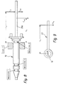
- FIG. 1 denotes a shaft which is mounted twice in a housing (not shown), for example the shaft of a fuel injection pump for internal combustion engines, which - at 11 - is driven by a - for example by the crankshaft of the internal combustion engine - Chain or toothed belt drive is driven and at the same time is subjected to bending stress.
- the bending force is indicated by an arrow F Z.
- a first bearing close to the drive is designated bearing A
- bearing B a second bearing remote from the drive
- bearing B “For bearings A and B, the (simplifying) assumption should apply that the forces exerted by shaft 10 on bearings A and B.
- the pump shaft 10 is special as a measuring shaft designed and only stored on the second distant bearing (bearing B) (see Fig. 7).
- the measuring points 1 and 2 each consist of two strain gauges 17, 18 and 19, 20 located opposite one another on the shaft circumference, which are connected in a half-bridge circuit and have an electrical resistance of 120 ohms. Measuring points 1 and 2 enable the determination of the bearing force L LA at bearing A.
- a measuring point 3 is also provided, which - like measuring points 1 and 2 - consists of two strain gauges opposite one another on the shaft circumference - here numbered 24, 25.
- the measuring point 3 already mentioned is set up on the side of the bearing B (see also FIG. 6).
- the additional tube 26 a is attached to the other end of the measuring shaft 10 here.
- the tube forces F and F additionally must first be determined.
- tube 26 a and additional tool 27 are mounted.
- the tube 26 a is a component which is somewhat modified compared to the tube 26 according to FIG. 7.
- the distances h, k, as shown in Figure 8, for measuring point 3 can then be determined from the given geometry. Similar to the arrangement according to FIG. 7, different bending moments are again determined, and the necessary weights are calculated according to the laws of mechanics (torque equilibrium). The measuring point 3 can then be calibrated for selected bending moments.
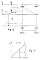
- a measuring point can be provided at point x 2 (measuring point 2 already mentioned). At location x 1 (in FIG. 10), however, a measuring point arrangement is not possible on shaft 10 for reasons of space, so that the bending moment cannot be measured directly at location x 1 . However, the bending moment at point x 3 (corresponds to the position of measuring point 1 already mentioned) can be measured. The desired bending moment at point x 1 can then be calculated by means of the slope of the bending moment curve by extrapolation. This can be seen in detail from FIG. 11.
- the bending moment at the respective position x i of the shaft 10 is required.
- the definition of the other variables indicated in FIGS. 10 and 11 reference is made to the above in connection 3 to 5 specified variable definition. From the determined bending moments M b (x 1) and M b (x 2) can be therefore, as stated, the bending moment M b calculate (x 3).
- the bending loads F Z and F kt can then be calculated from the bending moments M b (x 1 ) and M b (x 3 ) - according to the laws of mechanics - and finally the bearing forces F LA and F LB can be calculated from this.
- the calculation of the bearing forces can be simplified by forming a substitute force F ers from the sum of the forces F Z and F kt .
- a replacement lever arm z ers must then also be calculated, which replaces the individual lever arms z and p (see FIGS. 10 and 11 or 4 and 5).
- the replacement lever arm z ers can be determined using the replacement model shown in FIG. 12. Thereafter, the slope of the bending moment curve corresponds to how it is between the point of application of the force F kt and the bearing A as the resultant of the individual bending moments F Z. x and F kt . x gives exactly the slope of the bending moment curve of the equivalent force F ers .
- the point of application of the substitute force F ers on the shaft 10 results from the point at which the (imaginary) rearward extension of the bending moment curve (F Z + F kt ) ⁇ x intersects the abscissa x.
- the replacement lever arm z ers then represents the distance between the force application point F ers and the bearing A.
- the slope of the bending moment curve of F ers can be determined using the two measuring points. Since the forces F Z and F kt change during operation, the slope also varies.
- the replacement lever arm z ers can then be determined by dividing the measured bending moment by the respective incline for any point in time.
- the determination of the replacement lever arm z ers from the bending moment measured or calculated at the points x 2 and x 3 can be seen in detail from FIG. 13.
- the chamfer width b on bearing A (see FIG. 1) and the distance x DMS of measuring point 1 from bearing edge 12 (FIG. 1) are also taken into account.
Landscapes
- Engineering & Computer Science (AREA)
- Mechanical Engineering (AREA)
- General Engineering & Computer Science (AREA)
- Chemical & Material Sciences (AREA)
- Combustion & Propulsion (AREA)
- Physics & Mathematics (AREA)
- General Physics & Mathematics (AREA)
- Force Measurement Appropriate To Specific Purposes (AREA)
- Shafts, Cranks, Connecting Bars, And Related Bearings (AREA)
Abstract
Description
- Fig. 1
- eine zweifach gelagerte Welle, z.B. Einspritzpumpenwelle, die nur von einer einzigen Biegekraft belastet wird,
- Fig. 2
- die Lagerbelastung durch die Welle nach Fig. 1, anhand eines Ersatzmodells aus der technischen Mechanik,
- Fig. 3
- - in stirnseitiger Betrachtung - eine Kraftstoff-Einspritzpumpenwelle, die zum einen durch einen Kurbelwellentrieb und zum anderen durch einen Nockenwellentrieb biegebelastet wird,
- Fig. 4
- ein Ersatzmodell, das die Biegebelastungsverhältnisse durch den Kurbelwellentrieb (Ebene 1 - 1 in Fig. 3) zeigt,
- Fig. 5
- ein Ersatzmodell, das die Biegebelastungsverhältnisse durch den Nockenwellentrieb (Ebene 2 - 2 in Fig. 3) zeigt,
- Fig. 6
- eine Ausführungsform einer Einspritzpumpenwelle, die als Messwelle für die zu ermittelnden Lagerkräfte konzipiert ist,
- Fig. 7
- eine Messwelle entsprechend Fig. 1, in schematisierter Darstellung, zur Ermittlung der am antriebsnahen ersten Lager (s. Lager A" in Fig. 1) anfallenden Lagerkraft,
- Fig. 8
- - in Darstellung entsprechend Fig. 7 - eine Messwelle Zur Ermittlung der am antriebsferneren zweiten Lager (s. Lager B" in Fig. 1) anfallenden Lagerkraft,
- Fig. 9
- - in stirnseitiger Betrachtung bezüglich der Messwelle nach Fig. 7 bzw. 8 - ein Zusatzwerkzeug zur Anbringung eines Zusatzgewichts an der Messwelle nach Fig. 7 bzw. 8,
- Fig. 10
- ein Ersatzmodell mit Biegemomentverlauf für die Wellen-Biegebelastung nach Fig. 3 bis 5, wobei die in zwei unterschiedlichen Ebenen wirkenden unterschiedlichen Biegekräfte in eine resultierende Ebene projiziert sind,
- Fig. 11
- ein Diagramm zur Ermittlung (durch Extrapolation) des Biegemoments am Kraftangriffspunkt Fk (Fig. 10) bei am Punkt x3 (Fig. 10) gemessenem Biegemoment,
- Fig. 12
- ein Ersatzmodell zur Ermittlung einer aus den beiden Kräften FZ und Fkt (Fig. 10) resultierenden Ersatzkraft (Fers) aus den beiden Kräften FZ und Fkt (Fig. 10) und den von ihnen erzeugten Biegemomenten, und
- Fig. 13
- ein Diagramm zur Ermittlung (im Wege der Extrapolation) des zur Ersatzkraft (Fers, Fig. 12) zugehörigen Ersatzhebelarms (Zers).
Einspritzpumpe handelt, durch zwei in unterschiedlichen Ebenen - in Fig. 3 mit 1 - 1 bzw. 2 - 2 beziffert - wirkende Antriebs- bzw. Biegekräfte FZ und Fkt belastet. Es handelt sich zum einen um einen von der Kurbelwelle 28 betätigten Trieb 14 (z.B. Kettentrieb), der die Pumpenwelle 10 antreibt, und zum anderen um einen die Nockenwelle 15 antreibenden Trieb 16 (z.B. Zahnriementrieb). Wie Fig. 4 und 5 veranschaulichen, wirken die durch die Triebe 14 und 16 auf die Pumpenwelle 10 aufgebrachten Biegekräfte Fkt und Fz nicht nur in verschiedenen Ebenen (1 - 1 bzw. 2 - 2, Fig. 3), sondern auch mit unterschiedlichen Hebelarmen - p bzw. z - auf die Welle 10 ein. Im Einzelnen sind die Variablen in Fig. 4 und 5 wie folgt bezeichnet:
- c:
- Lagerabstand
- Fkt:
- Biegekraft durch Kettentrieb 14
- FLA:
- Lagerkraft am Lager A
- FLB:
- Lagerkraft am Lager B
- FZ:
- Biegekraft durch Zahnriementrieb 16
- p:
- Abstand Lagerkante 12 zur Biegekraft Fkt
- z:
- Abstand Mitte Zahnriementrieb 16 zu Lagerkante 12.
konzipiert und lediglich am antriebsferneren zweiten Lager (Lager B) gelagert (s. Fig. 7). Im Bereich des antriebsnahen ersten Lagers (Lager A) sind auf der Welle 10 zwei Messstellen - in Fig. 7 mit "Messstelle 1" und "Messstelle 2" bezeichnet - eingerichtet, die zur Ermittlung des Biegemomentverlaufs (vgl. hierzu Fig. 10) dienen. Fig. 6 macht deutlich, dass die Messstellen 1 und 2 aus je zwei am Wellenumfang gegenüberliegenden Dehnungsmessstreifen 17, 18 und 19, 20 bestehen, die in Halbbrücken-Schaltung geschaltet sind und einen elektrischen Widerstand von 120 Ohm aufweisen. Die Messstellen 1 und 2 ermöglichen die Ermittlung der Lagerkraft LLA am Lager A.
- f:
- Abstand Messstelle 1 zu Messstelle 2
- FAdapter:
- Kraft infolge Adapter zur Drehmomentkalibrierung
- Fk1 - Fk3:
- Kraft, hervorgerufen durch das aufgelegte Gewicht
- Fkupl:
- Kraft infolge Kupplungshälfte
- Frohr:
- Kraft, hervorgerufen durch die Rohrmasse des Rohres 26
- Fzus:
- Kraft durch das Gewicht der Zusatzwerkzeuge, die nötig sind, um das Kalibriergewicht aufzubringen (Gewichts-Auflageteller und Einhängevorrichtung sowie Büchse)
- h:
- Abstand Schwerpunkt Rohr 26 zum Gehäuseflansch
- k:
- Abstand Kalibriergewicht zum Gehäuseflansch
- I5
- Gehäuseflansch bis Lagerkante
- m:
- Abstand Kupplungshälfte bis Gehäuseflansch
- n:
- Abstand Adapter bis Gehäuseflansch
- XDMS:
- Abstand Lagerkante zur Dehnungsmessstreifen-Mitte
- Zus.Rohr:
- Rohr 26, das zusätzlich bei der Kalibrierung an der Welle 10 eingeschraubt wird.
- Fk5:
- Kraft (= aufgelegte Masse, multipliziert mit Erdbeschleunigung)
- K5:
- Hebelarm der am Zusatzwerkzeug 27 angreifenden Kraft Fk5, bezogen auf die Mitte der Messwelle 10
Claims (8)
- Verfahren zur Bestimmung der Lagerkräfte einer Welle, insbesondere für Einspritzpumpen von Brennkraftmaschinen, die durch ein antriebsnahes erstes Lager und ein davon beabstandetes antriebsferneres zweites Lager gelagert ist und an der außerhalb des Lagerbereichs - nach Art eines Kragträgers - Antriebskräfte angreifen, wobei das durch die Antriebskräfte auf die Welle ausgeübte (Umlauf-) Biegemoment an einer antriebsseitig auf der Welle neben dem ersten Lager angeordneten Messstelle ermittelt wird und daraus nach den Gesetzen der Mechanik die Lagerkräfte errechnet werden, dadurch gekennzeichnet, dass der zur Ermittlung der auf das erste Lager (Lager A) wirkenden Lagerkraft (FLA) erforderliche Biegemomentenverlauf und daraus die Biegebelastung (FZ und Fkt) der Welle (10) durch eine erste Messstelle (Messstelle 1) und eine mit dieser zusammenwirkende zweite Messstelle (Messstelle 2) bestimmt wird und dass die zweite Messstelle auf der Welle (10) im Bereich des ersten Lagers (Lager A) vorgesehen wird (Fig. 10 und 11).
- Verfahren nach Anspruch 1, zur Bestimmung der Lagerkraft (FLA) des ersten Lagers (Lager A), wobei die Welle (10) im weiteren Abstand (z) vom ersten Lager (Lager A) von einer ersten Biegekraft (FZ) und im näheren Abstand (p) vom ersten Lager (Lager A) von einer zweiten Biegekraft (Fkt) belastet wird, dadurch gekennzeichnet, dass das benötigte Biegemoment (Mx1) am Angriffspunkt (x1) der zweiten Biegekraft (Fkt) durch das an der ersten Messstelle (Messstelle 1) gemessene Biegemoment (Mx3) über die Steigung im Wege der Extrapolation errechnet wird und dass anschließend die beiden Biegekräfte (FZ, Fkt) aus dem an der zweiten Messstelle (Messstelle 2) gemessenen Biegemoment (Mx2) und dem errechneten Biegemoment (Mx1) nach den Gesetzen der Mechanik errechnet werden (Fig. 4, 5 und 10, 11).
- Verfahren nach Anspruch 2, wobei die Biegekräfte in unterschiedlichen Richtungen bzw. Ebenen (1 - 1 bzw. 2 - 2) auf die Welle (10) einwirken, dadurch gekennzeichnet, dass die aus den gemessenen Biegemomenten (Mx2 und Mx3) und dem errechneten Biegemoment (Mx1) errechneten Biegekräfte (FZ und Fkt) in einer resultierenden Ebene ermittelt werden (Fig. 10).
- Verfähren nach Anspruch 2 oder 3, dadurch gekennzeichnet, dass aus den beiden Biegekräften (FZ und Fkt) über die beiden Messstellen (1 und 2) eine einzige (resultierende) Ersatzkraft (Fers) und deren Hebelarm (zers) zum ersten Lager (Lager A) ermittelt werden (Fig. 12 und 13).
- Verfahren nach einem oder mehreren der vorstehenden Ansprüche, dadurch gekennzeichnet, dass vor Durchführung der Messungen zunächst die Messstellen (1, 2 und 3) an einer Messwelle (10) mit einem für alle Messstellen einheitlichen Biegemoment kalibriert werden (Fig. 7 und 8).
- Verfahren nach Anspruch 5, dadurch gekennzeichnet, dass die Messwelle (10) zur Kalibrierung nur am zweiten Lager (Lager B) gelagert ist.
- Verfahren nach Anspruch 5 und 6, dadurch gekennzeichnet, dass - zur Kalibrierung der beiden Messstellen (Messstellen 1 und 2) im Bereich des ersten Lagers (Lager A) - am antriebsseitigen Ende der Messwelle (10) ein zusätzliches Rohr (26) koaxial befestigt wird, an dem ein über einen Hebelarm (k5) durch eine Masse (Fk5) belastetes Zusatzwerkzeug (27) angeordnet wird.
- Verfahren nach Anspruch 5 und 6, dadurch gekennzeichnet, dass - zur Kalibrierung einer dritten Messstelle (Messstelle 3) im Bereich des zweiten Lagers (Lager B) an dem vom Antrieb abgewandten (rückseitigen) Ende der Messwelle (10) ein zusätzliches Rohr (26 a) koaxial befestigt wird, an dem ein über einen Hebelarm (k5) durch eine Masse (Fk5) belastetes Zusatzwerkzeug (27) angeordnet wird (Fig. 8 und 9).
Applications Claiming Priority (2)
| Application Number | Priority Date | Filing Date | Title |
|---|---|---|---|
| DE10157465 | 2001-11-23 | ||
| DE2001157465 DE10157465A1 (de) | 2001-11-23 | 2001-11-23 | Verfahren zur Bestimmung der Lagerkräfte einer angetriebenen Welle, insbesondere für Kraftstoffeinspritzpumpen von Brennkraftmaschinen |
Publications (3)
| Publication Number | Publication Date |
|---|---|
| EP1314871A2 true EP1314871A2 (de) | 2003-05-28 |
| EP1314871A3 EP1314871A3 (de) | 2003-10-22 |
| EP1314871B1 EP1314871B1 (de) | 2007-11-14 |
Family
ID=7706688
Family Applications (1)
| Application Number | Title | Priority Date | Filing Date |
|---|---|---|---|
| EP20020026079 Expired - Lifetime EP1314871B1 (de) | 2001-11-23 | 2002-11-22 | Verfahren zur Bestimmung der Lagerkräfte einer angetriebenen Welle, insbesondere für Kraftstoffeinspritzpumpen von Brennkraftmaschinen |
Country Status (2)
| Country | Link |
|---|---|
| EP (1) | EP1314871B1 (de) |
| DE (2) | DE10157465A1 (de) |
Family Cites Families (6)
| Publication number | Priority date | Publication date | Assignee | Title |
|---|---|---|---|---|
| GB1433133A (en) * | 1972-03-24 | 1976-04-22 | Gec Elliott Automation Ltd | Force measuring transducers |
| CH595622A5 (de) * | 1976-06-28 | 1978-02-15 | Heinrich Gruenbaum | |
| DE3909911C1 (de) * | 1989-03-25 | 1990-06-07 | Kleinewefers Gmbh, 4150 Krefeld, De | |
| DE4203551C2 (de) * | 1992-02-07 | 1994-01-13 | Gif Gmbh | Messwelle |
| DE19720325C1 (de) * | 1997-05-15 | 1998-10-15 | Hartmann & Braun Gmbh & Co Kg | Kraftmeßeinrichtung in einem Stellantrieb zur Steuerung von Armaturen |
| US6026786A (en) * | 1997-07-18 | 2000-02-22 | Caterpillar Inc. | Method and apparatus for controlling a fuel injector assembly of an internal combustion engine |
-
2001
- 2001-11-23 DE DE2001157465 patent/DE10157465A1/de not_active Withdrawn
-
2002
- 2002-11-22 DE DE50211194T patent/DE50211194D1/de not_active Expired - Lifetime
- 2002-11-22 EP EP20020026079 patent/EP1314871B1/de not_active Expired - Lifetime
Also Published As
| Publication number | Publication date |
|---|---|
| DE10157465A1 (de) | 2003-05-28 |
| EP1314871A3 (de) | 2003-10-22 |
| DE50211194D1 (de) | 2007-12-27 |
| EP1314871B1 (de) | 2007-11-14 |
Similar Documents
| Publication | Publication Date | Title |
|---|---|---|
| DE3331708C3 (de) | Vorrichtung zur Kontrolle und/oder Eichung einer Drehmomentmeßvorrichtung | |
| DE102008048131B4 (de) | Verfahren zur Messung einer Reibkraft | |
| EP0049701A2 (de) | Verfahren zur Steuerung des Förderbeginns einer Einspritzpumpe sowie Vorrichtung zur Durchführung dieses Verfahrens | |
| DE102016005889B4 (de) | Wellengenauigkeitsmessvorrichtung zum Messen der Genauigkeit einer Abtriebswelle eines Motors | |
| DE2541928A1 (de) | Vorrichtung sowie verfahren zum anziehen eines befestigungselementes mit einem steifigkeits-messgeraet | |
| EP0456244B1 (de) | Verfahren zum Prüfen von Verbrennungsmotoren bei der Montage | |
| DE10257614A1 (de) | Prüfstand und Prüfsystem zum Testen einer Vorrichtung zur Leistungsübertragung | |
| DE102009016123B4 (de) | Verfahren zum Zusammenbau und Bestimmen der Unwucht von Rotoren | |
| DE102015102249A1 (de) | Verfahren und Vorrichtung zur Bestimmung der Leistungsverteilung einer Verbrennungskraftmaschine | |
| EP1607714B1 (de) | Verfahren und Messanordnung zur Spielmessung an einem Achsgelenk | |
| DE60025371T2 (de) | Verfahren zur bearbeitung einer kurbelwelle mit originaler ausgleichregelung und verwendete vorrichtung | |
| EP4208701B1 (de) | Verfahren und vorrichtung zum ermitteln einer effizienz und/oder zum kalibrieren eines drehmoments eines rotierenden antriebsstrangs, insbesondere einer windenergieanlage | |
| EP0592628B1 (de) | Verfahren zur motorlastmessung | |
| EP1314871B1 (de) | Verfahren zur Bestimmung der Lagerkräfte einer angetriebenen Welle, insbesondere für Kraftstoffeinspritzpumpen von Brennkraftmaschinen | |
| DE10021491B4 (de) | Verfahren und Vorrichtung zum Ermitteln des Schwerpunktes eines anbaubaren Werkstücks, insbesondere einer Kolbenmaschine | |
| DE202005006590U1 (de) | Richt- und Stabilisierungsanlage mit einer Kraftmessvorrichtung zur Drehmomentmessung | |
| DE102020108328B3 (de) | Verfahren zur Herstellung eines Wälzlagersystems und System zur Ermittlung einer Anzahl von Sensoren und Sensorpositionen in einem Wälzlagersystem | |
| DE69123600T2 (de) | Verfahren und vorrichtung zum ausrichten einer welle | |
| EP0155648B1 (de) | Leistungsprüfstand für Motoren, insbesondere Landmaschinenmotoren | |
| DE3146185C2 (de) | Verfahren zur Einstellung einer bestimmten Winkellage der Kurbelwelle einer Brennkraftmaschine und Vorrichtung zur Durchführung dieses Verfahrens | |
| EP0634638A2 (de) | Justiereinrichtung für einen Rollenprüfstand | |
| EP3850332B1 (de) | Verfahren und system zur tarierung und/oder kalibrierung eines rotations-rheometers | |
| DE102004027588B3 (de) | Verfahren zur Montage eines Massenausgleichsgetriebes an einem Kurbelgehäuse einer eine Kurbelwelle aufweisenden Brennkraftmaschine | |
| DE19752194B4 (de) | Verfahren und System zum Messen der Interferenz zwischen einem Ventil und einem Kolben eines Verbrennungsmotors | |
| DE4328143A1 (de) | Verfahren für eine Einrichtung zur Gewichtsbestimmung von an einem Schlepper angehängten Lasten |
Legal Events
| Date | Code | Title | Description |
|---|---|---|---|
| PUAI | Public reference made under article 153(3) epc to a published international application that has entered the european phase |
Free format text: ORIGINAL CODE: 0009012 |
|
| AK | Designated contracting states |
Designated state(s): AT BE BG CH CY CZ DE DK EE ES FI FR GB GR IE IT LI LU MC NL PT SE SK TR |
|
| AX | Request for extension of the european patent |
Extension state: AL LT LV MK RO SI |
|
| PUAL | Search report despatched |
Free format text: ORIGINAL CODE: 0009013 |
|
| AK | Designated contracting states |
Kind code of ref document: A3 Designated state(s): AT BE BG CH CY CZ DE DK EE ES FI FR GB GR IE IT LI LU MC NL PT SE SK TR |
|
| AX | Request for extension of the european patent |
Extension state: AL LT LV MK RO SI |
|
| 17P | Request for examination filed |
Effective date: 20040422 |
|
| AKX | Designation fees paid |
Designated state(s): DE FR GB IT |
|
| GRAP | Despatch of communication of intention to grant a patent |
Free format text: ORIGINAL CODE: EPIDOSNIGR1 |
|
| GRAS | Grant fee paid |
Free format text: ORIGINAL CODE: EPIDOSNIGR3 |
|
| GRAA | (expected) grant |
Free format text: ORIGINAL CODE: 0009210 |
|
| AK | Designated contracting states |
Kind code of ref document: B1 Designated state(s): DE FR GB IT |
|
| REG | Reference to a national code |
Ref country code: GB Ref legal event code: FG4D Free format text: NOT ENGLISH |
|
| REF | Corresponds to: |
Ref document number: 50211194 Country of ref document: DE Date of ref document: 20071227 Kind code of ref document: P |
|
| ET | Fr: translation filed | ||
| PLBE | No opposition filed within time limit |
Free format text: ORIGINAL CODE: 0009261 |
|
| STAA | Information on the status of an ep patent application or granted ep patent |
Free format text: STATUS: NO OPPOSITION FILED WITHIN TIME LIMIT |
|
| 26N | No opposition filed |
Effective date: 20080815 |
|
| REG | Reference to a national code |
Ref country code: FR Ref legal event code: PLFP Year of fee payment: 14 |
|
| PGFP | Annual fee paid to national office [announced via postgrant information from national office to epo] |
Ref country code: GB Payment date: 20151123 Year of fee payment: 14 |
|
| REG | Reference to a national code |
Ref country code: FR Ref legal event code: PLFP Year of fee payment: 15 |
|
| PGFP | Annual fee paid to national office [announced via postgrant information from national office to epo] |
Ref country code: FR Payment date: 20161124 Year of fee payment: 15 |
|
| PGFP | Annual fee paid to national office [announced via postgrant information from national office to epo] |
Ref country code: IT Payment date: 20161124 Year of fee payment: 15 |
|
| GBPC | Gb: european patent ceased through non-payment of renewal fee |
Effective date: 20161122 |
|
| PG25 | Lapsed in a contracting state [announced via postgrant information from national office to epo] |
Ref country code: GB Free format text: LAPSE BECAUSE OF NON-PAYMENT OF DUE FEES Effective date: 20161122 |
|
| REG | Reference to a national code |
Ref country code: FR Ref legal event code: ST Effective date: 20180731 |
|
| PG25 | Lapsed in a contracting state [announced via postgrant information from national office to epo] |
Ref country code: FR Free format text: LAPSE BECAUSE OF NON-PAYMENT OF DUE FEES Effective date: 20171130 Ref country code: IT Free format text: LAPSE BECAUSE OF NON-PAYMENT OF DUE FEES Effective date: 20171122 |
|
| PGFP | Annual fee paid to national office [announced via postgrant information from national office to epo] |
Ref country code: DE Payment date: 20220125 Year of fee payment: 20 |
|
| REG | Reference to a national code |
Ref country code: DE Ref legal event code: R071 Ref document number: 50211194 Country of ref document: DE |