EP1314852A1 - Tunnel excavating machine and method for its recovery - Google Patents
Tunnel excavating machine and method for its recovery Download PDFInfo
- Publication number
- EP1314852A1 EP1314852A1 EP02025625A EP02025625A EP1314852A1 EP 1314852 A1 EP1314852 A1 EP 1314852A1 EP 02025625 A EP02025625 A EP 02025625A EP 02025625 A EP02025625 A EP 02025625A EP 1314852 A1 EP1314852 A1 EP 1314852A1
- Authority
- EP
- European Patent Office
- Prior art keywords
- cutter head
- outer peripheral
- excavating machine
- central portion
- peripheral portion
- Prior art date
- Legal status (The legal status is an assumption and is not a legal conclusion. Google has not performed a legal analysis and makes no representation as to the accuracy of the status listed.)
- Withdrawn
Links
- 238000000034 method Methods 0.000 title claims description 8
- 238000011084 recovery Methods 0.000 title description 12
- 230000002093 peripheral effect Effects 0.000 claims abstract description 80
- 230000005540 biological transmission Effects 0.000 claims description 8
- 238000009412 basement excavation Methods 0.000 description 13
- 238000010276 construction Methods 0.000 description 8
- 239000002002 slurry Substances 0.000 description 6
- 239000002440 industrial waste Substances 0.000 description 5
- 238000004519 manufacturing process Methods 0.000 description 5
- 230000003247 decreasing effect Effects 0.000 description 4
- 239000000654 additive Substances 0.000 description 3
- 239000000470 constituent Substances 0.000 description 3
- 239000004576 sand Substances 0.000 description 2
- 230000005641 tunneling Effects 0.000 description 2
- 235000006506 Brasenia schreberi Nutrition 0.000 description 1
- 244000267222 Brasenia schreberi Species 0.000 description 1
- 230000000996 additive effect Effects 0.000 description 1
- 238000007599 discharging Methods 0.000 description 1
- 238000009429 electrical wiring Methods 0.000 description 1
- 238000012423 maintenance Methods 0.000 description 1
- 239000000463 material Substances 0.000 description 1
- 238000012986 modification Methods 0.000 description 1
- 230000004048 modification Effects 0.000 description 1
- 238000012856 packing Methods 0.000 description 1
- 239000002689 soil Substances 0.000 description 1
- XLYOFNOQVPJJNP-UHFFFAOYSA-N water Substances O XLYOFNOQVPJJNP-UHFFFAOYSA-N 0.000 description 1
- 238000003466 welding Methods 0.000 description 1
Images




Classifications
-
- E—FIXED CONSTRUCTIONS
- E21—EARTH OR ROCK DRILLING; MINING
- E21D—SHAFTS; TUNNELS; GALLERIES; LARGE UNDERGROUND CHAMBERS
- E21D9/00—Tunnels or galleries, with or without linings; Methods or apparatus for making thereof; Layout of tunnels or galleries
- E21D9/06—Making by using a driving shield, i.e. advanced by pushing means bearing against the already placed lining
- E21D9/08—Making by using a driving shield, i.e. advanced by pushing means bearing against the already placed lining with additional boring or cutting means other than the conventional cutting edge of the shield
- E21D9/0875—Making by using a driving shield, i.e. advanced by pushing means bearing against the already placed lining with additional boring or cutting means other than the conventional cutting edge of the shield with a movable support arm carrying cutting tools for attacking the front face, e.g. a bucket
- E21D9/0879—Making by using a driving shield, i.e. advanced by pushing means bearing against the already placed lining with additional boring or cutting means other than the conventional cutting edge of the shield with a movable support arm carrying cutting tools for attacking the front face, e.g. a bucket the shield being provided with devices for lining the tunnel, e.g. shuttering
Definitions
- This invention relates to a tunnel excavating machine, which is advanced to excavate a tunnel of a predetermined length, and in which its constituent members such as a cutter head can then be separated and recovered, and a method for recovering the tunnel excavating machine.
- the tunnel excavating machine and the method for its recovery are preferred when used for a pressurized slurry shield excavator, a muddy water shield excavator, and a tunnel boring machine.
- a shield excavator is constituted in the following manner: A disk-shaped cutter head is rotatably mounted in a front portion of a cylindrical excavating machine body, and the cutter head is supported rotationally drivably by a drive device. Many shield jacks for advancing the excavating machine body are mounted in a rear portion of the excavating machine body. An erector device for assembling segments onto an inner wall surface of an existing tunnel is also mounted in the rear portion of the excavating machine body.
- the shield jacks are stretched, with the cutter head being rotated by the drive device, the excavating machine body receives a reaction force from the established segments and moves forward.
- Many cutter bits attached to the cutter head excavate strata lying ahead, and can form a tunnel thereby.
- a departure pit and an arrival pit are dug beforehand in this construction zone. Then, the shield excavator is carried into the departure pit. With a reaction force for excavation being secured within the departure pit, the shield excavator penetrates the strata lying ahead through a departure port, performing excavation along a predetermined route. When the shield excavator advances up to the arrival pit, a shield body is pulled out into the arrival pit through an arrival port formed beforehand. In this manner, a tunnel is constructed at a predetermined location.
- the shield excavator which has arrived at the arrival pit, is disassembled, and a part of it is recovered above ground. The remainder is buried in the ground as a structure for the tunnel. That is, the shield excavator is treated in the following manner: First, the cutter head is divided into small pieces by a gas cutter, and lifted above ground by a crane through the arrival pit. Then, the drive device for the cutter head is similarly divided into small pieces by a gas cutter, and lifted above ground by the crane through the arrival pit. The shield jacks, the erector device, and a soil discharge device (a slurry feed pipe, a slurry discharge pipe, an agitator, a screw conveyor, etc.) are detached from the excavator body, and lifted above ground by the crane. The remaining excavator body is connected to the existing segments and buried as a part of the tunnel structure. In this case, the cutter head and the drive device therefor, which have been divided and lifted above ground, are handled as scrap.
- the present invention has been accomplished in an attempt to solve the above-mentioned problems. Its object is to provide a tunnel excavating machine which has made it possible to recover a structure constituting the excavating machine and reuse it, and a method for recovering the tunnel excavating machine.
- a tunnel excavating machine having a rotationally drivable cutter head mounted in a front portion of a cylindrical excavating machine body, wherein the cutter head is composed of a divisible central portion, and an outer peripheral portion located on an outer peripheral side of the central portion, and is provided with a connecting pin which moves from one of to the other of the central portion and the outer peripheral portion to connect the central portion and the outer peripheral portion.
- the outer peripheral portion of the cutter head is separated from the excavating machine body, and is easily recovered above ground, so that it can be reused. Since the recovered member is reused in the excavating machine, the manufacturing cost of the excavating machine can be decreased, and increases in industrial wastes due to scrapping can be curtailed. Moreover, simply by moving the connecting pin, engagement between the central portion and the outer peripheral portion can be released, and the outer peripheral portion can be easily detached. Furthermore, the operator does not need to enter a working place during this disassembly operation, so that the operability and the safety of the operation can be improved.
- the central portion of the cutter head may be connected to an output transmission portion of a cutter drive device loaded in the excavating machine body, and the outer peripheral portion may be detachably connected to the central portion.
- the central portion and the outer peripheral portion can be easily attached and detached, so that the operability of the cutter head recovery operation can be improved.
- the cutter drive device may have rotors rotatably supported in the front portion of the excavating machine body, and a drive motor for driving the rotors, and the central portion may be connected to the rotors via an intermediate beam extending forward from the rotors.
- the removal operations for the central portion and the outer peripheral portion are performed in the chamber, so that the operability of the cutter head recovery operation can be improved.
- a connecting jack having the connecting pin may be provided in one of the central portion and the outer peripheral portion of the cutter head, and a connecting block having a connecting hole, which the connecting pin can be engaged with and disengaged from, may be provided in the other of the central portion and the outer peripheral portion.
- driving force transmission paths may be provided in an interior of the connecting pin.
- the operations for removing the hydraulic pipings, electric power cables, etc. can be performed simultaneously and easily during the operation for detaching the outer peripheral portion from the central portion of the cutter head. Hence, the operability can be improved.
- the driving force transmission paths may be hydraulic pipings for driving a copy cutter mounted on the outer peripheral portion of the cutter head.
- the central portion of the cutter head may be constituted by having front end portions of a plurality of radial spokes connected by a connecting ring
- the outer peripheral portion of the cutter head may be constituted by having front end portions of a plurality of radial spokes connected by a connecting ring.
- the central portion and the outer peripheral portion of the cutter head can each be constituted of a simple construction with the use of the spokes and connecting ring, and can be rendered lightweight thereby.
- the cutter head central portion and the cutter head outer peripheral portion can be connected easily by a connecting pin, and the operation for detaching the cutter head outer peripheral portion from the cutter head central portion can be performed easily.
- the outer peripheral portion of the cutter head may be in the shape of a ring, and may be separable into a plurality of parts in a circumferential direction.
- the member to be recovered is rendered lightweight, so that the recovery operation can be facilitated, and the departure pit and the arrival pit can be formed with small diameters.
- a tunnel excavating machine comprising:
- the cutter head can be easily disassembled and recovered, so that it can be reused. Since the recovered cutter head is reused in an excavating machine, the manufacturing cost of the excavating machine can be decreased, and increases in industrial wastes due to scrapping can be curtailed.
- a method for recovering a tunnel excavating machine comprising:
- the cutter head can be easily disassembled and recovered, so that it can be reused. Since the recovered cutter head is reused in an excavating machine, the manufacturing cost of the excavating machine can be decreased, and increases in industrial wastes due to scrapping can be curtailed.
- FIG. 1 shows a front of a tunnel excavating machine according to the embodiment of the present invention.
- FIG. 2 schematically shows a section of the tunnel excavating machine according to the present embodiment.
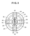
- FIG. 3 shows a front of a cutter head central portion.
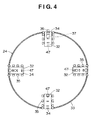
- FIG. 4 shows a front of a cutter head outer peripheral portion.
- FIG. 5 shows a section of a junction between the cutter head central portion and the cutter head outer peripheral portion.
- FIG. 6 shows a section of a connecting jack.
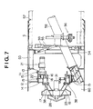
- FIG. 7 schematically shows a section of the tunnel excavating machine from which the cutter head outer peripheral portion has been detached.
- an excavating machine body 11 is cylindrical in shape, and has a pair of bulkheads 12 and 13 formed in a fore-and-aft direction in a front end portion thereof.
- a drive component body 14 is fixed to flanges of the bulkheads 12, 13 by a plurality of bolts 15.
- a rotating ring 17, as an output transmission portion, is rotatably supported by the drive component body 14 via a bearing 16.
- a ring gear 18 is joined to a rear part of the rotating ring 17, while a cutter head 20 is mounted on a front part of the rotating ring 17 via a plurality of intermediate beams 19.
- a plurality of drive motors 21 are mounted on the drive component body 14, and drive gears 22 of the respective drive motors 21 are in mesh with the ring gear 18, so that a cutter drive device is constituted by the drive component body 14, rotating ring 17, ring gear 18, and drive motors 21. Hence, when the drive motor 21 is driven to drive the drive gear 22 rotationally, the cutter head 20 can be rotated via the ring gear 18 and the rotating ring 17.
- the cutter head 20 is composed of a cutter head central portion 23, and a cutter head outer peripheral portion 24 located on an outer peripheral side of the cutter head central portion 23.
- the cutter head central portion 23 is detachable from the rotating ring 17, while the cutter head outer peripheral portion 24 is detachable from the cutter head central portion 23. That is, as shown in FIGS. 2 and 3, the cutter head central portion 23 comprises a plurality of spokes 26 connected radially to a central portion 25, and a plurality of connecting rings 27 connected to front end portions of the respective spokes 26.
- a fishtail bit 28 is fixed to the central portion 25, many forward bits 29 are fixed to the front surfaces of the spokes 26, and cutter bits 30 are fixed to both sides of the spokes 26.
- a rotary joint 31 is mounted on a central portion of the drive component body 14 to accommodate electrical wiring, hydraulic hoses, etc. in its interior.
- the cutter head outer peripheral portion 24 is constituted in the following manner: A plurality of spokes 32, corresponding to the respective spokes 26 of the cutter head central portion 23, are connected to a connecting ring 33. Many forward bits 34 are fixed to the front surfaces of the spokes 32, and cutter bits 35 are fixed to both sides of the spokes 32. A copy cutter 36 can appear at or disappear from the front end of one or two of the spokes 32 by the action of a hydraulic jack 37.
- the cutter head outer peripheral portion 24 takes a ring shape, but may be separable into a plurality of parts in the circumferential direction in consideration of ease of recovery.
- the intermediate beams 19 can be attached to and detached from the rotating ring 17 using a plurality of bolts 38.
- the cutter head outer peripheral portion 24 can be attached to and detached from the cutter head central portion 23 using connecting pins 45 to be described later.
- a hydraulic connecting jack 40 is fixed to an end plate 39 at the front end of each spoke 26 by fixing bolts 41.
- the connecting jack 40 comprises a hollow casing 42 in which a drive rod 43 and a piston 44 integral therewith are movably fitted, and the connecting pin 45 is formed integrally at the front end of the drive rod 43, as shown in FIGS. 2, 5 and 6.
- An oil pressure is fed to and discharged from oil compartments 42a, 42b within the casing 42 which are defined by the piston 44, whereby the connecting pin 45 can be caused to appear and disappear.
- a connecting block 47 is fixed to an end plate 46 at the base end of each spoke 32 by fixing bolts (not shown).
- the connecting block 47 has a connecting hole 48 formed therein which the connecting pin 45 of the connecting jack 40 can be engaged with and disengaged from.
- a plurality of through-holes 49, 50, as driving force transmission paths, are provided within the drive rod 43 and the connecting pin 45.
- These through-holes 49, 50 are hydraulic pipings for driving the hydraulic jack 37 for the copy cutter 36, and have piping ports 49a, 49b, 50a, 50b provided at the ends thereof.
- Connecting hoses 51a, 51b, 52a, 52b for feeding and discharging an oil pressure can be connected to the piping ports 49a, 49b, 50a, 50b.
- the plurality of through-holes 49, 50 formed within the drive rod 43 and the connecting pin 45 serve as the hydraulic pipings for the copy cutter 36, but may be used as disposition holes for electric power cables of various sensors, or as feed holes for slurry fluidifying additives.
- a plurality of shield jacks 53 are arranged parallel along the circumferential direction in a rear portion of the excavating machine body 11.
- the shield jacks 53 are stretched rearward in an excavating direction and pressed against existing segments S which have been constructed on the inner peripheral surface of an excavated tunnel.
- the excavating machine body 11 can be moved forward by a reaction force generated thereby.
- a swivel ring 55 is supported, in a pivotally drivable manner, at a rear end portion of the excavating machine body 11 via a support bracket 54, and an erector device 56 for assembling segments S is mounted on the swivel ring 55.
- a plurality of tail packings 57 which intimately contact the outer peripheral surfaces of the existing segments S, are attached to the rear end portion of the excavating machine body 11 to prevent muck and muddy water from invading the interior of the excavating machine body 11.
- a screw conveyor 58 is disposed in a forwardly inclined manner within the excavating machine body 11, and is held in this inclined state by a support rod 59.
- a front end portion of the screw conveyor 58 communicates with a chamber 60 via openings of the bulkheads 12, 13 so that earth and sand excavated by the cutter head 20 can be discharged to the outside.
- Tunnel excavation work by the tunnel excavating machine of the above-described embodiment, and recovery work for the tunnel excavating machine after excavation will be described below.
- a departure pit of a predetermined depth is dug at the position where excavation is to be started, and the tunnel excavating machine is carried into the departure pit.
- the shield jacks 53 are stretched to move the excavating machine body 11 from within the departure pit while obtaining a reaction force for excavation.
- the upright wall of the departure pit is dug to start tunnel excavation work.
- Earth and sand produced in accordance with excavation of the strata by the cutter head 20 are discharged from the chamber 60 to the outside by the screw conveyor 58.
- segments S are assembled in a ringlike shape by the erector device 56 to proceed with the construction of a tunnel.
- An arrival pit of a predetermined depth is dug at the position in a construction zone where excavation is to be completed.
- the tunnel constructed by the tunnel excavating machine, starting at the departure pit, is extended to this arrival pit.
- the arrival pit needs to be dug to suit the size of the cutter head 20, etc. which are to be separated and recovered.
- a suspending jig (not shown) is attached to the cutter head outer peripheral portion 24, and a rope lowered into the arrival pit from a crane installed above ground is connected to the suspending jig.
- the cutter head outer peripheral portion 24 is lifted above ground by this crane for the purpose of recovery. In this case, if the cutter head outer peripheral portion 24 is separable into a plurality of parts in the circumferential direction, the separate parts are lifted above ground by the crane for recovery.
- the bolts 38 are loosened to detach the cutter head central portion 23 from the rotating ring 17, and the cutter head central portion 23 is moved forward along the rails.
- a suspending jig (not shown) is attached to the cutter head central portion 23, and a rope lowered into the arrival pit from the crane installed above ground is connected to the suspending jig.
- the cutter head central portion 23 is lifted above ground by this crane for the purpose of recovery.
- the bolts 15 are loosened to detach the drive component body 14 (cutter drive device) from the excavating machine body 11, and the drive component body 14 is moved forward along the rails.
- a suspending jig is attached to the drive component body 14, and a rope lowered into the arrival pit from the crane is connected to the suspending jig.
- the drive component body 14 is lifted above ground by this crane for the purpose of recovery. In this case, if the diameter of the arrival pit is sufficient, the cutter head central portion 23 and the drive component body 14 may be integrally lifted above ground and recovered.
- the cutter head 20 and the cutter drive device are detached from the excavating machine body 11 and recovered. Then, the shield jacks 53, erector device 56, screw conveyor 58, and various sensors are detached and recovered.
- the excavating machine body 11 left underground is bonded to the existing segments S by welding or concreting for use as a tunnel structure.
- the cutter head 20 is composed of the cutter head central portion 23 and the cutter head outer peripheral portion 24.
- the drive component body 14 mounted with the rotating ring 17, ring gear 18, and drive motors 21 is detachable from the excavating machine body 11.
- the cutter head central portion 23 is detachable from the rotating ring 17, and the cutter head outer peripheral portion 24 is detachable from the cutter head central portion 23.
- the cutter head outer peripheral portion 24, cutter head central portion 23 and drive component body 14 can be separated in this sequence from the excavating machine body 11. These members can be recovered above ground from within the arrival pit, and can be reused. Since the cutter head 20 and drive motors 21 are reused, the manufacturing cost of the excavating machine can be decreased, and increases in industrial wastes due to scrapping can be curtailed. Where necessary, moreover, the excavating machine body can be separated into constituent parts, recovered from within the arrival pit, and reused.
- the fishtail bit 28, forward bits 29, 34, cutter bits 30, 35 and copy cutter 36, which have been worn, may be replaced.
- the drive component body 14 including the drive motors 21 may be given some maintenance. In reusing the drive component body 14, the number of the drive motors 21 to be mounted may be changed in response to a required output different according to the diameter of the tunnel to be excavated or the type of the strata to be dug.
- the connecting jack 40 which enables the connecting pin 45 to appear and disappear, is mounted in the spoke 26 of the cutter head central portion 23, while the connecting block 47 having the connecting hole 48, which the connecting pin 45 can be engaged with and disengaged from, is mounted in the spoke 32 of the cutter head outer peripheral portion 24.
- the connecting jack 40 simply by driving the connecting jack 40 to pull out the connecting pin 45 engaged with the connecting hole 48, therefore, the engagement between the cutter head central portion 23 and the cutter head outer peripheral portion 24 can be released, and the cutter head outer peripheral portion 24 can be easily detached from the cutter head central portion 23.
- This disassembly operation may be performed by remote control of the connecting jack 40. The operator does not need to enter a working place or the chamber 60, but the safety of the operation can be ensured sufficiently.
- the plurality of through-holes 49, 50 are provided in the drive rod 43 and the connecting pin 45, and these through-holes 49, 50 can be used as the driving hydraulic pipings for the copy cutter 36, as disposition holes for electric power cables of various sensors, and as feed holes for slurry fluidifying additives.
- these through-holes 49, 50 can be used as the driving hydraulic pipings for the copy cutter 36, as disposition holes for electric power cables of various sensors, and as feed holes for slurry fluidifying additives.
- the arrival pit is dug beforehand together with the departure pit, and after completion of tunneling work, the cutter head 20, etc. are disassembled and recovered above ground from within the arrival pit. However, they can be returned to the departure pit, and recovered. That is, when the tunnel has been excavated over a predetermined distance, the rotation of the cutter head 20 is stopped. Then, the connecting pin 45 is pulled out of the connecting hole 48 by the connecting jack 40 to release the engagement between the cutter head central portion 23 and the cutter head outer peripheral portion 24, and the cutter head outer peripheral portion 24 is detached from the cutter head central portion 23. Then, the cutter head central portion 23 and the drive component body 14 are detached in this sequence from the excavating machine body 11.
- the shield jacks 53, erector device 56, screw conveyor 58, and various sensors are detached from the excavating machine body 11. These members are transported by a transport bogie movably supported within the existing tunnel, and recovered from the departure pit. Furthermore, the cutter head outer peripheral portion 24 and the cutter head central portion 23 are similarly transported by the transport bogie and recovered from the departure pit.
- the cutter head outer peripheral portion 24 is in the shape of a ring, but may be constituted as two divided parts or three or more divided parts.
- each of the members, which is single, is lightweight, so that the recovery operation can be facilitated, and the departure pit and the arrival pit can be formed with small diameters.
- the excavating machine body 11 is buried underground to serve as a tunnel structure. However, if the segments are assembled and bonded to the inner wall surface of the tunnel by the erector device 56 as far as they reach the arrival pit, the excavating machine body 11 may be recovered above ground from the arrival pit.
- the connecting jack 40 is mounted in the cutter head central portion 23, and the connecting jack 40 is expanded and contracted, whereby the connecting pin 45 is engaged with and disengaged from the connecting hole 48 of the cutter head outer peripheral portion 24, so that the cutter head central portion 23 and the cutter head outer peripheral portion 24 are connected to and separated from each other.
- the connecting jack 40 and the connecting pin 45 may be provided in the cutter head outer peripheral portion 24, and the connecting hole 48 may be provided in the cutter head central portion 23.
- the connecting jack 40 may use an air cylinder or electric motor as well as a hydraulic cylinder which can be remote controlled.
- the connecting pin 45 may be a fixing bolt.
Landscapes
- Engineering & Computer Science (AREA)
- Mining & Mineral Resources (AREA)
- Environmental & Geological Engineering (AREA)
- Life Sciences & Earth Sciences (AREA)
- General Life Sciences & Earth Sciences (AREA)
- Geochemistry & Mineralogy (AREA)
- Geology (AREA)
- Excavating Of Shafts Or Tunnels (AREA)
Abstract
In a tunnel excavating machine, a cutter head (20) is
composed of a cutter head central portion (23) and a cutter
head outer peripheral portion (24). A drive component body
(14) mounted with a rotating ring (17), a ring gear (18),
and drive motors (21) is detachable from an excavating
machine body (11). The cutter head central portion (23)
is detachable from the rotating ring (17), and the cutter
head outer peripheral portion (24) is detachable from the
cutter head central portion (23).
Description
- The entire disclosure of Japanese Patent Application No. 2001-355520 filed on November 21, 2001 including specification, claims, drawings and summary is incorporated herein by reference in its entirety.
- This invention relates to a tunnel excavating machine, which is advanced to excavate a tunnel of a predetermined length, and in which its constituent members such as a cutter head can then be separated and recovered, and a method for recovering the tunnel excavating machine. The tunnel excavating machine and the method for its recovery are preferred when used for a pressurized slurry shield excavator, a muddy water shield excavator, and a tunnel boring machine.
- Generally, a shield excavator is constituted in the following manner: A disk-shaped cutter head is rotatably mounted in a front portion of a cylindrical excavating machine body, and the cutter head is supported rotationally drivably by a drive device. Many shield jacks for advancing the excavating machine body are mounted in a rear portion of the excavating machine body. An erector device for assembling segments onto an inner wall surface of an existing tunnel is also mounted in the rear portion of the excavating machine body. Thus, when the shield jacks are stretched, with the cutter head being rotated by the drive device, the excavating machine body receives a reaction force from the established segments and moves forward. Many cutter bits attached to the cutter head excavate strata lying ahead, and can form a tunnel thereby.
- In constructing a tunnel in a predetermined construction zone with the use of such a shield excavator, a departure pit and an arrival pit are dug beforehand in this construction zone. Then, the shield excavator is carried into the departure pit. With a reaction force for excavation being secured within the departure pit, the shield excavator penetrates the strata lying ahead through a departure port, performing excavation along a predetermined route. When the shield excavator advances up to the arrival pit, a shield body is pulled out into the arrival pit through an arrival port formed beforehand. In this manner, a tunnel is constructed at a predetermined location.
- The shield excavator, which has arrived at the arrival pit, is disassembled, and a part of it is recovered above ground. The remainder is buried in the ground as a structure for the tunnel. That is, the shield excavator is treated in the following manner: First, the cutter head is divided into small pieces by a gas cutter, and lifted above ground by a crane through the arrival pit. Then, the drive device for the cutter head is similarly divided into small pieces by a gas cutter, and lifted above ground by the crane through the arrival pit. The shield jacks, the erector device, and a soil discharge device (a slurry feed pipe, a slurry discharge pipe, an agitator, a screw conveyor, etc.) are detached from the excavator body, and lifted above ground by the crane. The remaining excavator body is connected to the existing segments and buried as a part of the tunnel structure. In this case, the cutter head and the drive device therefor, which have been divided and lifted above ground, are handled as scrap.
- From the aspect of the global environment, increases in industrial wastes due to scrapping of tunnel excavating machines are not desirable. From the aspect of the manufacturing cost of tunnel excavating machines, too, scrapping only from excavation work in a single construction zone is inefficient, and the materials for scrap should be reused.
- The present invention has been accomplished in an attempt to solve the above-mentioned problems. Its object is to provide a tunnel excavating machine which has made it possible to recover a structure constituting the excavating machine and reuse it, and a method for recovering the tunnel excavating machine.
- As described in detail in the embodiment, according to a first aspect of the invention, there is provided a tunnel excavating machine having a rotationally drivable cutter head mounted in a front portion of a cylindrical excavating machine body, wherein the cutter head is composed of a divisible central portion, and an outer peripheral portion located on an outer peripheral side of the central portion, and is provided with a connecting pin which moves from one of to the other of the central portion and the outer peripheral portion to connect the central portion and the outer peripheral portion.
- Therefore, after tunnel excavation work is completed, the outer peripheral portion of the cutter head is separated from the excavating machine body, and is easily recovered above ground, so that it can be reused. Since the recovered member is reused in the excavating machine, the manufacturing cost of the excavating machine can be decreased, and increases in industrial wastes due to scrapping can be curtailed. Moreover, simply by moving the connecting pin, engagement between the central portion and the outer peripheral portion can be released, and the outer peripheral portion can be easily detached. Furthermore, the operator does not need to enter a working place during this disassembly operation, so that the operability and the safety of the operation can be improved.
- In the tunnel excavating machine, the central portion of the cutter head may be connected to an output transmission portion of a cutter drive device loaded in the excavating machine body, and the outer peripheral portion may be detachably connected to the central portion. Thus, the central portion and the outer peripheral portion can be easily attached and detached, so that the operability of the cutter head recovery operation can be improved.
- In the tunnel excavating machine, the cutter drive device may have rotors rotatably supported in the front portion of the excavating machine body, and a drive motor for driving the rotors, and the central portion may be connected to the rotors via an intermediate beam extending forward from the rotors. Thus, the removal operations for the central portion and the outer peripheral portion are performed in the chamber, so that the operability of the cutter head recovery operation can be improved.
- In the tunnel excavating machine, a connecting jack having the connecting pin may be provided in one of the central portion and the outer peripheral portion of the cutter head, and a connecting block having a connecting hole, which the connecting pin can be engaged with and disengaged from, may be provided in the other of the central portion and the outer peripheral portion. Thus, the operability of the operations for attaching and detaching the central portion and the outer peripheral portion of the cutter head can be improved using a simple construction.
- In the tunnel excavating machine, driving force transmission paths may be provided in an interior of the connecting pin. Thus, the operations for removing the hydraulic pipings, electric power cables, etc. can be performed simultaneously and easily during the operation for detaching the outer peripheral portion from the central portion of the cutter head. Hence, the operability can be improved.
- In the tunnel excavating machine, the driving force transmission paths may be hydraulic pipings for driving a copy cutter mounted on the outer peripheral portion of the cutter head. Thus, simplification of the structure and improvement of the operability can be achieved.
- In the tunnel excavating machine, the central portion of the cutter head may be constituted by having front end portions of a plurality of radial spokes connected by a connecting ring, and the outer peripheral portion of the cutter head may be constituted by having front end portions of a plurality of radial spokes connected by a connecting ring. Thus, the central portion and the outer peripheral portion of the cutter head can each be constituted of a simple construction with the use of the spokes and connecting ring, and can be rendered lightweight thereby. The cutter head central portion and the cutter head outer peripheral portion can be connected easily by a connecting pin, and the operation for detaching the cutter head outer peripheral portion from the cutter head central portion can be performed easily.
- In the tunnel excavating machine, the outer peripheral portion of the cutter head may be in the shape of a ring, and may be separable into a plurality of parts in a circumferential direction. Thus, the member to be recovered is rendered lightweight, so that the recovery operation can be facilitated, and the departure pit and the arrival pit can be formed with small diameters.
- According to a second aspect of the invention, there is provided a method for recovering a tunnel excavating machine, comprising:
- advancing the tunnel excavating machine to excavate a tunnel;
- stopping rotation of a cutter head when the cutter head penetrates into an arrival pit;
- then extracting a connecting pin connecting a cutter head central portion and a cutter head outer peripheral portion;
- separating the cutter head outer peripheral portion from the cutter head central portion;
- recovering the cutter head outer peripheral portion above ground through the arrival pit;
- then separating the cutter head central portion from an excavating machine body; and
- recovering the cutter head central portion above ground through the arrival pit.
-
- Thus, the cutter head can be easily disassembled and recovered, so that it can be reused. Since the recovered cutter head is reused in an excavating machine, the manufacturing cost of the excavating machine can be decreased, and increases in industrial wastes due to scrapping can be curtailed.
- According to a third aspect of the invention, there is provided a method for recovering a tunnel excavating machine, comprising:
- advancing the tunnel excavating machine to excavate a tunnel for a predetermined distance by a cutter head rotated;
- then stopping rotation of the cutter head;
- then extracting a connecting pin connecting a cutter head central portion and a cutter head outer peripheral portion;
- separating the cutter head outer peripheral portion from the cutter head central portion;
- then separating the cutter head central portion and a cutter drive device from an excavating machine body;
- recovering the cutter head central portion and the cutter drive device above ground through the existing tunnel lying behind; and
- then recovering the cutter head outer peripheral portion above ground through the existing tunnel lying behind.
-
- Thus, the cutter head can be easily disassembled and recovered, so that it can be reused. Since the recovered cutter head is reused in an excavating machine, the manufacturing cost of the excavating machine can be decreased, and increases in industrial wastes due to scrapping can be curtailed.
- The present invention will become more fully understood from the detailed description given hereinbelow and the accompanying drawings which are given by way of illustration only, and thus are not limitative of the present invention, and wherein:
- FIG. 1 is a front view of a tunnel excavating machine according to an embodiment of the present invention; FIG. 2 is a schematic sectional view of the tunnel excavating machine according to the present embodiment; FIG. 3 is a front view of a cutter head central portion; FIG. 4 is a front view of a cutter head outer peripheral portion; FIG. 5 is a sectional view showing a junction between the cutter head central portion and the cutter head outer peripheral portion; FIG. 6 is a sectional view of a connecting jack; and FIG. 7 is a schematic sectional view of the tunnel excavating machine from which the cutter head outer peripheral portion has been detached.
-
- An embodiment of the present invention will now be described in detail with reference to the accompanying drawings, which in no way limit the invention.
- FIG. 1 shows a front of a tunnel excavating machine according to the embodiment of the present invention. FIG. 2 schematically shows a section of the tunnel excavating machine according to the present embodiment. FIG. 3 shows a front of a cutter head central portion. FIG. 4 shows a front of a cutter head outer peripheral portion. FIG. 5 shows a section of a junction between the cutter head central portion and the cutter head outer peripheral portion. FIG. 6 shows a section of a connecting jack. FIG. 7 schematically shows a section of the tunnel excavating machine from which the cutter head outer peripheral portion has been detached.
- In the tunnel excavating machine of the present embodiment, as shown in FIGS. 1 and 2, an excavating
machine body 11 is cylindrical in shape, and has a pair ofbulkheads drive component body 14 is fixed to flanges of thebulkheads bolts 15. Arotating ring 17, as an output transmission portion, is rotatably supported by thedrive component body 14 via abearing 16. Aring gear 18 is joined to a rear part of therotating ring 17, while acutter head 20 is mounted on a front part of therotating ring 17 via a plurality ofintermediate beams 19. A plurality ofdrive motors 21 are mounted on thedrive component body 14, and drive gears 22 of therespective drive motors 21 are in mesh with thering gear 18, so that a cutter drive device is constituted by thedrive component body 14, rotatingring 17,ring gear 18, and drivemotors 21. Hence, when thedrive motor 21 is driven to drive thedrive gear 22 rotationally, thecutter head 20 can be rotated via thering gear 18 and therotating ring 17. - The
cutter head 20 is composed of a cutter headcentral portion 23, and a cutter head outerperipheral portion 24 located on an outer peripheral side of the cutter headcentral portion 23. The cutter headcentral portion 23 is detachable from the rotatingring 17, while the cutter head outerperipheral portion 24 is detachable from the cutter headcentral portion 23. That is, as shown in FIGS. 2 and 3, the cutter headcentral portion 23 comprises a plurality ofspokes 26 connected radially to acentral portion 25, and a plurality of connectingrings 27 connected to front end portions of therespective spokes 26. Afishtail bit 28 is fixed to thecentral portion 25, manyforward bits 29 are fixed to the front surfaces of thespokes 26, andcutter bits 30 are fixed to both sides of thespokes 26. A rotary joint 31 is mounted on a central portion of thedrive component body 14 to accommodate electrical wiring, hydraulic hoses, etc. in its interior. - As shown in FIGS. 2 and 4, on the other hand, the cutter head outer
peripheral portion 24 is constituted in the following manner: A plurality ofspokes 32, corresponding to therespective spokes 26 of the cutter headcentral portion 23, are connected to a connectingring 33. Manyforward bits 34 are fixed to the front surfaces of thespokes 32, andcutter bits 35 are fixed to both sides of thespokes 32. Acopy cutter 36 can appear at or disappear from the front end of one or two of thespokes 32 by the action of ahydraulic jack 37. The cutter head outerperipheral portion 24 takes a ring shape, but may be separable into a plurality of parts in the circumferential direction in consideration of ease of recovery. - In the cutter head
central portion 23, theintermediate beams 19 can be attached to and detached from the rotatingring 17 using a plurality ofbolts 38. The cutter head outerperipheral portion 24 can be attached to and detached from the cutter headcentral portion 23 using connectingpins 45 to be described later. - That is, in the cutter head
central portion 23, a hydraulic connectingjack 40 is fixed to anend plate 39 at the front end of each spoke 26 by fixingbolts 41. The connectingjack 40 comprises ahollow casing 42 in which adrive rod 43 and apiston 44 integral therewith are movably fitted, and the connectingpin 45 is formed integrally at the front end of thedrive rod 43, as shown in FIGS. 2, 5 and 6. An oil pressure is fed to and discharged fromoil compartments 42a, 42b within thecasing 42 which are defined by thepiston 44, whereby the connectingpin 45 can be caused to appear and disappear. In the cutter head outerperipheral portion 24, a connectingblock 47 is fixed to anend plate 46 at the base end of each spoke 32 by fixing bolts (not shown). The connectingblock 47 has a connectinghole 48 formed therein which the connectingpin 45 of the connectingjack 40 can be engaged with and disengaged from. - A plurality of through-
holes drive rod 43 and the connectingpin 45. These through-holes hydraulic jack 37 for thecopy cutter 36, and havepiping ports hoses piping ports holes drive rod 43 and the connectingpin 45 serve as the hydraulic pipings for thecopy cutter 36, but may be used as disposition holes for electric power cables of various sensors, or as feed holes for slurry fluidifying additives. - As shown in FIGS. 1 and 2, moreover, a plurality of shield jacks 53 are arranged parallel along the circumferential direction in a rear portion of the excavating
machine body 11. The shield jacks 53 are stretched rearward in an excavating direction and pressed against existing segments S which have been constructed on the inner peripheral surface of an excavated tunnel. As a result, the excavatingmachine body 11 can be moved forward by a reaction force generated thereby. Furthermore, aswivel ring 55 is supported, in a pivotally drivable manner, at a rear end portion of the excavatingmachine body 11 via asupport bracket 54, and anerector device 56 for assembling segments S is mounted on theswivel ring 55. - A plurality of
tail packings 57, which intimately contact the outer peripheral surfaces of the existing segments S, are attached to the rear end portion of the excavatingmachine body 11 to prevent muck and muddy water from invading the interior of the excavatingmachine body 11. Ascrew conveyor 58 is disposed in a forwardly inclined manner within the excavatingmachine body 11, and is held in this inclined state by asupport rod 59. A front end portion of thescrew conveyor 58 communicates with achamber 60 via openings of thebulkheads cutter head 20 can be discharged to the outside. - Tunnel excavation work by the tunnel excavating machine of the above-described embodiment, and recovery work for the tunnel excavating machine after excavation will be described below.
- To form a tunnel by excavation, as shown in FIGS. 1 and 2, a departure pit of a predetermined depth is dug at the position where excavation is to be started, and the tunnel excavating machine is carried into the departure pit. With the
cutter head 20 being rotated by thedrive motors 21, the shield jacks 53 are stretched to move the excavatingmachine body 11 from within the departure pit while obtaining a reaction force for excavation. During this movement, the upright wall of the departure pit is dug to start tunnel excavation work. Earth and sand produced in accordance with excavation of the strata by thecutter head 20 are discharged from thechamber 60 to the outside by thescrew conveyor 58. At the same time, segments S are assembled in a ringlike shape by theerector device 56 to proceed with the construction of a tunnel. - An arrival pit of a predetermined depth is dug at the position in a construction zone where excavation is to be completed. The tunnel constructed by the tunnel excavating machine, starting at the departure pit, is extended to this arrival pit. In this case, the arrival pit needs to be dug to suit the size of the
cutter head 20, etc. which are to be separated and recovered. After tunneling work in the predetermined construction zone is completed and thecutter head 20 of the tunnel excavating machine penetrates into the arrival pit, the rotation of thecutter head 20 by thedrive motors 21 is stopped. Then, this tunnel excavating machine is disassembled, and its constituent members are recovered from the arrival pit. - That is, when the front end portion of the excavating
machine body 11 penetrates into the arrival pit, the rotation of thecutter head 20 is stopped. In this state, the respective connectingjacks 40 of the cutter headcentral portion 23 are driven to contract thedrive rods 43, thereby pulling the connectingpins 45 out of the connectingholes 48 of the connectingblocks 47 fixed to the cutter head outerperipheral portion 24. By so doing, the connection between the cutter headcentral portion 23 and the cutter head outerperipheral portion 24 is released. Thus, as shown in FIG. 7, the cutter head outerperipheral portion 24 is detached from the cutter headcentral portion 23, and the cutter head outerperipheral portion 24 is moved forward by dedicated jacks along rails (not shown) laid in the arrival pit. Then, a suspending jig (not shown) is attached to the cutter head outerperipheral portion 24, and a rope lowered into the arrival pit from a crane installed above ground is connected to the suspending jig. The cutter head outerperipheral portion 24 is lifted above ground by this crane for the purpose of recovery. In this case, if the cutter head outerperipheral portion 24 is separable into a plurality of parts in the circumferential direction, the separate parts are lifted above ground by the crane for recovery. - Then, the
bolts 38 are loosened to detach the cutter headcentral portion 23 from the rotatingring 17, and the cutter headcentral portion 23 is moved forward along the rails. Then, a suspending jig (not shown) is attached to the cutter headcentral portion 23, and a rope lowered into the arrival pit from the crane installed above ground is connected to the suspending jig. The cutter headcentral portion 23 is lifted above ground by this crane for the purpose of recovery. - Then, the
bolts 15 are loosened to detach the drive component body 14 (cutter drive device) from the excavatingmachine body 11, and thedrive component body 14 is moved forward along the rails. Then, a suspending jig is attached to thedrive component body 14, and a rope lowered into the arrival pit from the crane is connected to the suspending jig. Thedrive component body 14 is lifted above ground by this crane for the purpose of recovery. In this case, if the diameter of the arrival pit is sufficient, the cutter headcentral portion 23 and thedrive component body 14 may be integrally lifted above ground and recovered. - In the above-described manner, the
cutter head 20 and the cutter drive device are detached from the excavatingmachine body 11 and recovered. Then, the shield jacks 53,erector device 56,screw conveyor 58, and various sensors are detached and recovered. The excavatingmachine body 11 left underground is bonded to the existing segments S by welding or concreting for use as a tunnel structure. - In the tunnel excavating machine of the present embodiment, the
cutter head 20 is composed of the cutter headcentral portion 23 and the cutter head outerperipheral portion 24. Thedrive component body 14 mounted with therotating ring 17,ring gear 18, and drivemotors 21 is detachable from the excavatingmachine body 11. The cutter headcentral portion 23 is detachable from the rotatingring 17, and the cutter head outerperipheral portion 24 is detachable from the cutter headcentral portion 23. - After tunnel excavation work is completed, therefore, the cutter head outer
peripheral portion 24, cutter headcentral portion 23 and drivecomponent body 14 can be separated in this sequence from the excavatingmachine body 11. These members can be recovered above ground from within the arrival pit, and can be reused. Since thecutter head 20 and drivemotors 21 are reused, the manufacturing cost of the excavating machine can be decreased, and increases in industrial wastes due to scrapping can be curtailed. Where necessary, moreover, the excavating machine body can be separated into constituent parts, recovered from within the arrival pit, and reused. - If the
cutter head 20 is recovered, thefishtail bit 28,forward bits cutter bits copy cutter 36, which have been worn, may be replaced. Thedrive component body 14 including thedrive motors 21 may be given some maintenance. In reusing thedrive component body 14, the number of thedrive motors 21 to be mounted may be changed in response to a required output different according to the diameter of the tunnel to be excavated or the type of the strata to be dug. - In the present embodiment, moreover, the connecting
jack 40, which enables the connectingpin 45 to appear and disappear, is mounted in thespoke 26 of the cutter headcentral portion 23, while the connectingblock 47 having the connectinghole 48, which the connectingpin 45 can be engaged with and disengaged from, is mounted in thespoke 32 of the cutter head outerperipheral portion 24. Simply by driving the connectingjack 40 to pull out the connectingpin 45 engaged with the connectinghole 48, therefore, the engagement between the cutter headcentral portion 23 and the cutter head outerperipheral portion 24 can be released, and the cutter head outerperipheral portion 24 can be easily detached from the cutter headcentral portion 23. This disassembly operation may be performed by remote control of the connectingjack 40. The operator does not need to enter a working place or thechamber 60, but the safety of the operation can be ensured sufficiently. - Besides, the plurality of through-
holes drive rod 43 and the connectingpin 45, and these through-holes copy cutter 36, as disposition holes for electric power cables of various sensors, and as feed holes for slurry fluidifying additives. Thus, operations for separating the hydraulic pipings, electric power cables, and slurry fluidifying additive feed pipes become easy during the operation for disassembly of the cutter head outerperipheral portion 24 from the cutter headcentral portion 23. - In the above-described embodiment, the arrival pit is dug beforehand together with the departure pit, and after completion of tunneling work, the
cutter head 20, etc. are disassembled and recovered above ground from within the arrival pit. However, they can be returned to the departure pit, and recovered. That is, when the tunnel has been excavated over a predetermined distance, the rotation of thecutter head 20 is stopped. Then, the connectingpin 45 is pulled out of the connectinghole 48 by the connectingjack 40 to release the engagement between the cutter headcentral portion 23 and the cutter head outerperipheral portion 24, and the cutter head outerperipheral portion 24 is detached from the cutter headcentral portion 23. Then, the cutter headcentral portion 23 and thedrive component body 14 are detached in this sequence from the excavatingmachine body 11. On this occasion, the shield jacks 53,erector device 56,screw conveyor 58, and various sensors are detached from the excavatingmachine body 11. These members are transported by a transport bogie movably supported within the existing tunnel, and recovered from the departure pit. Furthermore, the cutter head outerperipheral portion 24 and the cutter headcentral portion 23 are similarly transported by the transport bogie and recovered from the departure pit. - In the above-described embodiment, the cutter head outer
peripheral portion 24 is in the shape of a ring, but may be constituted as two divided parts or three or more divided parts. In this case, each of the members, which is single, is lightweight, so that the recovery operation can be facilitated, and the departure pit and the arrival pit can be formed with small diameters. Besides, the excavatingmachine body 11 is buried underground to serve as a tunnel structure. However, if the segments are assembled and bonded to the inner wall surface of the tunnel by theerector device 56 as far as they reach the arrival pit, the excavatingmachine body 11 may be recovered above ground from the arrival pit. - In the present embodiment, moreover, the connecting
jack 40 is mounted in the cutter headcentral portion 23, and the connectingjack 40 is expanded and contracted, whereby the connectingpin 45 is engaged with and disengaged from the connectinghole 48 of the cutter head outerperipheral portion 24, so that the cutter headcentral portion 23 and the cutter head outerperipheral portion 24 are connected to and separated from each other. However, the connectingjack 40 and the connectingpin 45 may be provided in the cutter head outerperipheral portion 24, and the connectinghole 48 may be provided in the cutter headcentral portion 23. Furthermore, the connectingjack 40 may use an air cylinder or electric motor as well as a hydraulic cylinder which can be remote controlled. The connectingpin 45 may be a fixing bolt. - While the present invention has been described by the aforementioned embodiment, it is to be understood that the invention is not limited thereby, but may be varied in many other ways. Such variations are not to be regarded as a departure from the spirit and scope of the invention, and all such modifications as would be obvious to one skilled in the art are intended to be included within the scope of the appended claims.
Claims (10)
- A tunnel excavating machine having a rotationally drivable cutter head (20) mounted in a front portion of a cylindrical excavating machine body (11), characterized in that
said cutter head (20) is composed of a divisible central portion (23), and an outer peripheral portion (24) located on an outer peripheral side of said central portion (23), and is provided with a connecting pin (45) which moves from one of to other of said central portion (23) and said outer peripheral portion (24) to connect said central portion (23) and said outer peripheral portion (24). - A tunnel excavating machine according to claim 1, characterized in that said central portion (23) of said cutter head (20) is connected to an output transmission portion (17) of a cutter drive device (14, 21) loaded in said excavating machine body (11), and said outer peripheral portion (24) is detachably connected to said central portion (23).
- A tunnel excavating machine according to claim 2, characterized in that said cutter drive device (14, 21) has rotors (17, 18) rotatably supported in the front portion of said excavating machine body (11), and a drive motor (21) for driving said rotors (17, 18), and said central portion (23) is connected to said rotors (17, 18) via an intermediate beam (19) extending forward from said rotors (17, 18).
- A tunnel excavating machine according to claim 1, characterized in that a connecting jack (40) having said connecting pin (45) is provided in one of said central portion (23) and said outer peripheral portion (24) of said cutter head (20), and a connecting block (47) having a connecting hole (48), which said connecting pin (45) can be engaged with and disengaged from, is provided in said other of said central portion (23) and said outer peripheral portion (24).
- A tunnel excavating machine according to claim 1, characterized in that driving force transmission paths (49, 50) are provided in an interior of said connecting pin (45).
- A tunnel excavating machine according to claim 5, characterized in that said driving force transmission paths (49, 50) are hydraulic pipings (51a, 51b, 52a, 52b) for driving a copy cutter (36) mounted on said outer peripheral portion (24) of said cutter head (20).
- A tunnel excavating machine according to claim 1, characterized in that said central portion (23) of said cutter head (20) is constituted by having front end portions of a plurality of radial spokes (26) connected by a connecting ring (27), and said outer peripheral portion (24) of said cutter head (20) is constituted by having front end portions of a plurality of radial spokes (32) connected by a connecting ring (33).
- A tunnel excavating machine according to claim 1, characterized in that said outer peripheral portion (24) of said cutter head (20) is in a shape of a ring, and is separable into a plurality of parts in a circumferential direction.
- A method for recovering a tunnel excavating machine, characterized by:advancing said tunnel excavating machine to excavate a tunnel;stopping rotation of a cutter head (20) when said cutter head (20) penetrates into an arrival pit;then extracting a connecting pin (45) connecting a cutter head central portion (23) and a cutter head outer peripheral portion (24);separating said cutter head outer peripheral portion (24) from said cutter head central portion (23);recovering said cutter head outer peripheral portion (24) above ground through said arrival pit;then separating said cutter head central portion (23) from an excavating machine body (11); andrecovering said cutter head central portion (23) above ground through said arrival pit.
- A method for recovering a tunnel excavating machine, characterized by:advancing said tunnel excavating machine to excavate a tunnel for a predetermined distance by a cutter head (20) rotated;then stopping rotation of said cutter head (20);then extracting a connecting pin (45) connecting a cutter head central portion (23) and a cutter head outer peripheral portion (24);separating said cutter head outer peripheral portion (24) from said cutter head central portion (23);then separating said cutter head central portion (23) and a cutter drive device (17, 21) from an excavating machine body (11);recovering said cutter head central portion (23) and said cutter drive device (17, 21) above ground through the existing tunnel lying behind; andthen recovering said cutter head outer peripheral portion (24) above ground through the existing tunnel lying behind.
Applications Claiming Priority (2)
| Application Number | Priority Date | Filing Date | Title |
|---|---|---|---|
| JP2001355520 | 2001-11-21 | ||
| JP2001355520A JP2003155892A (en) | 2001-11-21 | 2001-11-21 | Tunnel excavator and collection method of the tunnel excavator |
Publications (1)
| Publication Number | Publication Date |
|---|---|
| EP1314852A1 true EP1314852A1 (en) | 2003-05-28 |
Family
ID=19167209
Family Applications (1)
| Application Number | Title | Priority Date | Filing Date |
|---|---|---|---|
| EP02025625A Withdrawn EP1314852A1 (en) | 2001-11-21 | 2002-11-19 | Tunnel excavating machine and method for its recovery |
Country Status (3)
| Country | Link |
|---|---|
| EP (1) | EP1314852A1 (en) |
| JP (1) | JP2003155892A (en) |
| CN (1) | CN1226531C (en) |
Cited By (7)
| Publication number | Priority date | Publication date | Assignee | Title |
|---|---|---|---|---|
| CN101598024B (en) * | 2009-05-20 | 2011-01-26 | 江阴市港东机械有限公司 | Shield cutter-head mechanism of shield tunnel boring machine |
| CN102581434A (en) * | 2012-03-15 | 2012-07-18 | 中交天和机械设备制造有限公司 | Hardfacing method for screw conveyor |
| JP2014025268A (en) * | 2012-07-27 | 2014-02-06 | Mitsubishi Heavy Industries Mechatronics Systems Ltd | Rotary joint |
| JP2014025269A (en) * | 2012-07-27 | 2014-02-06 | Mitsubishi Heavy Industries Mechatronics Systems Ltd | Rotary joint |
| CN105065018A (en) * | 2015-08-09 | 2015-11-18 | 张永忠 | Double-arched door tunnel excavator |
| CN109184720A (en) * | 2018-10-09 | 2019-01-11 | 南京林业大学 | It is a kind of can subregion independence thermometric shield model test cutterhead and test method |
| DE102019216495B4 (en) | 2019-10-25 | 2024-01-25 | Thyssenkrupp Ag | Bearing arrangement for storing a drill head in a tunnel boring machine and tunnel boring machine |
Families Citing this family (13)
| Publication number | Priority date | Publication date | Assignee | Title |
|---|---|---|---|---|
| JP4734541B2 (en) * | 2005-09-29 | 2011-07-27 | 清水建設株式会社 | Method of recovering shield machine and shield machine using the method |
| JP4693799B2 (en) * | 2007-02-21 | 2011-06-01 | 株式会社奥村組 | Tunnel excavator assembly method |
| CN101975563A (en) * | 2010-09-14 | 2011-02-16 | 沈阳重型机械集团有限责任公司 | Wear detection device of shield scraper |
| JP5705662B2 (en) * | 2011-06-15 | 2015-04-22 | 株式会社奥村組 | Shield excavator |
| CN103758526A (en) * | 2014-01-03 | 2014-04-30 | 上海市基础工程集团有限公司 | Concave cutterhead for large-diameter earth pressure balanced pipe-jacking machine of long-range jacking construction |
| CN103982195A (en) * | 2014-05-13 | 2014-08-13 | 淮南矿业(集团)有限责任公司 | Full-face tunnel boring machine |
| CN104948197A (en) * | 2015-06-17 | 2015-09-30 | 蚌埠市行星工程机械有限公司 | Shield tunneling machine scraper mechanism capable of telescopically moving |
| CN105736006B (en) * | 2016-03-22 | 2018-11-09 | 大连理工大学 | High-pressure water jet full face rock tunnel boring machine cutterhead design method |
| CN110043274A (en) * | 2019-05-29 | 2019-07-23 | 中铁三局集团第二工程有限公司 | A kind of variable-diameter adjustment structure of shield machine weak soil knife disc tool |
| CN110410088B (en) * | 2019-08-14 | 2022-02-25 | 中国铁建重工集团股份有限公司 | Retractable tunneling machine and retraction method thereof |
| CN111287760B (en) * | 2020-03-27 | 2025-03-04 | 上海力行工程技术发展有限公司 | A standard modular cutterhead and its conversion operation method |
| CN112160765A (en) * | 2020-09-27 | 2021-01-01 | 谢林志 | Tunnel excavator drill bit |
| CN113236268B (en) * | 2021-06-08 | 2023-01-24 | 上海市基础工程集团有限公司 | Arrangement structure of small-diameter shield tunneling machine profiling cutter tool |
Citations (8)
| Publication number | Priority date | Publication date | Assignee | Title |
|---|---|---|---|---|
| US3382002A (en) * | 1965-07-23 | 1968-05-07 | John R. Tabor | Rotary cutter wheel tunneling machine |
| EP0432901A1 (en) * | 1989-12-13 | 1991-06-19 | Taisei Corporation | Method and apparatus for excavating a shaft and tunnel |
| JPH07324591A (en) * | 1994-05-31 | 1995-12-12 | Fujita Corp | Construction method of shield construction corresponding to geological changes |
| EP0781895A1 (en) * | 1995-12-28 | 1997-07-02 | Taisei Corporation | Method and apparatus of excavation for underground structures of variable cross sectional area |
| JPH116387A (en) * | 1997-06-13 | 1999-01-12 | Kawasaki Heavy Ind Ltd | Two-stage shield machine |
| JPH11200764A (en) * | 1998-01-16 | 1999-07-27 | Mitsubishi Heavy Ind Ltd | Separable tunnel excavator and tunnel excavation method |
| JPH11210375A (en) * | 1998-01-29 | 1999-08-03 | Shinwa Gijutsu Kaihatsu Kk | Propulsive machine for excavation |
| JP2002188391A (en) * | 2000-10-10 | 2002-07-05 | Mitsubishi Heavy Ind Ltd | Tunnel excavator and method of dismantling tunnel excavator |
-
2001
- 2001-11-21 JP JP2001355520A patent/JP2003155892A/en not_active Withdrawn
-
2002
- 2002-11-19 EP EP02025625A patent/EP1314852A1/en not_active Withdrawn
- 2002-11-21 CN CNB021513716A patent/CN1226531C/en not_active Expired - Fee Related
Patent Citations (8)
| Publication number | Priority date | Publication date | Assignee | Title |
|---|---|---|---|---|
| US3382002A (en) * | 1965-07-23 | 1968-05-07 | John R. Tabor | Rotary cutter wheel tunneling machine |
| EP0432901A1 (en) * | 1989-12-13 | 1991-06-19 | Taisei Corporation | Method and apparatus for excavating a shaft and tunnel |
| JPH07324591A (en) * | 1994-05-31 | 1995-12-12 | Fujita Corp | Construction method of shield construction corresponding to geological changes |
| EP0781895A1 (en) * | 1995-12-28 | 1997-07-02 | Taisei Corporation | Method and apparatus of excavation for underground structures of variable cross sectional area |
| JPH116387A (en) * | 1997-06-13 | 1999-01-12 | Kawasaki Heavy Ind Ltd | Two-stage shield machine |
| JPH11200764A (en) * | 1998-01-16 | 1999-07-27 | Mitsubishi Heavy Ind Ltd | Separable tunnel excavator and tunnel excavation method |
| JPH11210375A (en) * | 1998-01-29 | 1999-08-03 | Shinwa Gijutsu Kaihatsu Kk | Propulsive machine for excavation |
| JP2002188391A (en) * | 2000-10-10 | 2002-07-05 | Mitsubishi Heavy Ind Ltd | Tunnel excavator and method of dismantling tunnel excavator |
Non-Patent Citations (4)
| Title |
|---|
| PATENT ABSTRACTS OF JAPAN vol. 1996, no. 04 30 April 1996 (1996-04-30) * |
| PATENT ABSTRACTS OF JAPAN vol. 1999, no. 12 29 October 1999 (1999-10-29) * |
| PATENT ABSTRACTS OF JAPAN vol. 1999, no. 13 30 November 1999 (1999-11-30) * |
| PATENT ABSTRACTS OF JAPAN vol. 2002, no. 11 6 November 2002 (2002-11-06) * |
Cited By (7)
| Publication number | Priority date | Publication date | Assignee | Title |
|---|---|---|---|---|
| CN101598024B (en) * | 2009-05-20 | 2011-01-26 | 江阴市港东机械有限公司 | Shield cutter-head mechanism of shield tunnel boring machine |
| CN102581434A (en) * | 2012-03-15 | 2012-07-18 | 中交天和机械设备制造有限公司 | Hardfacing method for screw conveyor |
| JP2014025268A (en) * | 2012-07-27 | 2014-02-06 | Mitsubishi Heavy Industries Mechatronics Systems Ltd | Rotary joint |
| JP2014025269A (en) * | 2012-07-27 | 2014-02-06 | Mitsubishi Heavy Industries Mechatronics Systems Ltd | Rotary joint |
| CN105065018A (en) * | 2015-08-09 | 2015-11-18 | 张永忠 | Double-arched door tunnel excavator |
| CN109184720A (en) * | 2018-10-09 | 2019-01-11 | 南京林业大学 | It is a kind of can subregion independence thermometric shield model test cutterhead and test method |
| DE102019216495B4 (en) | 2019-10-25 | 2024-01-25 | Thyssenkrupp Ag | Bearing arrangement for storing a drill head in a tunnel boring machine and tunnel boring machine |
Also Published As
| Publication number | Publication date |
|---|---|
| JP2003155892A (en) | 2003-05-30 |
| CN1420256A (en) | 2003-05-28 |
| CN1226531C (en) | 2005-11-09 |
Similar Documents
| Publication | Publication Date | Title |
|---|---|---|
| JP2003155892A (en) | Tunnel excavator and collection method of the tunnel excavator | |
| JP5475521B2 (en) | Tunnel excavator | |
| JP6012073B2 (en) | How to replace excavation members of tunnel excavator | |
| JP2008266996A (en) | Tunnel excavator and tunnel excavation method | |
| JP3534657B2 (en) | Ground excavation method | |
| JP3439745B2 (en) | Shield excavator and method of excavating pit with shield excavator | |
| JP3311321B2 (en) | Shield machine for removing existing tunnels | |
| JP6517085B2 (en) | Method of constructing secondary tunnel tunnel and branch shield used in the method of construction | |
| JP4931635B2 (en) | How to reassemble the excavator | |
| JP7121638B2 (en) | Circumferential shield excavator | |
| JP5854770B2 (en) | Tunnel excavator for underground joint method with towable cutter replacement mechanism | |
| JP2002206391A (en) | Tunnel excavator and its recovering method | |
| JPH0489992A (en) | Existing pipe duct enlarging method and shield excavation device used with the method | |
| JP2002129875A (en) | Tunnel excavator and method of dismantling tunnel excavator | |
| JP2003214091A (en) | Tunnel boring machine | |
| JP2002188391A (en) | Tunnel excavator and method of dismantling tunnel excavator | |
| JP4718990B2 (en) | Method of retaining soil near tunnel face | |
| JP4334954B2 (en) | Method and apparatus for widening underground space | |
| JP5292246B2 (en) | Tunnel excavator with switching lining | |
| JP3219746B2 (en) | Existing tunnel removal method and shield tunneling machine for removal of existing tunnel | |
| JP2015017389A (en) | Tunnel excavator | |
| JP3853325B2 (en) | How to collect and recover shield excavators | |
| JP4966551B2 (en) | Recovery method for tunnel excavator | |
| JP2808371B2 (en) | Dismantling method of existing pipeline | |
| JP3380737B2 (en) | Drilling propulsion machine |
Legal Events
| Date | Code | Title | Description |
|---|---|---|---|
| PUAI | Public reference made under article 153(3) epc to a published international application that has entered the european phase |
Free format text: ORIGINAL CODE: 0009012 |
|
| 17P | Request for examination filed |
Effective date: 20021119 |
|
| AK | Designated contracting states |
Designated state(s): AT BE BG CH CY CZ DE DK EE ES FI FR GB GR IE IT LI LU MC NL PT SE SK TR |
|
| AX | Request for extension of the european patent |
Extension state: AL LT LV MK RO SI |
|
| AKX | Designation fees paid |
Designated state(s): DE ES FR |
|
| STAA | Information on the status of an ep patent application or granted ep patent |
Free format text: STATUS: THE APPLICATION IS DEEMED TO BE WITHDRAWN |
|
| 18D | Application deemed to be withdrawn |
Effective date: 20060627 |