EP1314530A1 - Kunststoffspritzgiesssystem und Verfahren zur Herstellung von Kunststoff-Formteilen - Google Patents
Kunststoffspritzgiesssystem und Verfahren zur Herstellung von Kunststoff-Formteilen Download PDFInfo
- Publication number
- EP1314530A1 EP1314530A1 EP02024923A EP02024923A EP1314530A1 EP 1314530 A1 EP1314530 A1 EP 1314530A1 EP 02024923 A EP02024923 A EP 02024923A EP 02024923 A EP02024923 A EP 02024923A EP 1314530 A1 EP1314530 A1 EP 1314530A1
- Authority
- EP
- European Patent Office
- Prior art keywords
- injection molding
- molding unit
- mold
- base material
- injection
- Prior art date
- Legal status (The legal status is an assumption and is not a legal conclusion. Google has not performed a legal analysis and makes no representation as to the accuracy of the status listed.)
- Granted
Links
Images


Classifications
-
- B—PERFORMING OPERATIONS; TRANSPORTING
- B29—WORKING OF PLASTICS; WORKING OF SUBSTANCES IN A PLASTIC STATE IN GENERAL
- B29C—SHAPING OR JOINING OF PLASTICS; SHAPING OF MATERIAL IN A PLASTIC STATE, NOT OTHERWISE PROVIDED FOR; AFTER-TREATMENT OF THE SHAPED PRODUCTS, e.g. REPAIRING
- B29C45/00—Injection moulding, i.e. forcing the required volume of moulding material through a nozzle into a closed mould; Apparatus therefor
- B29C45/03—Injection moulding apparatus
- B29C45/13—Injection moulding apparatus using two or more injection units co-operating with a single mould
-
- B—PERFORMING OPERATIONS; TRANSPORTING
- B29—WORKING OF PLASTICS; WORKING OF SUBSTANCES IN A PLASTIC STATE IN GENERAL
- B29C—SHAPING OR JOINING OF PLASTICS; SHAPING OF MATERIAL IN A PLASTIC STATE, NOT OTHERWISE PROVIDED FOR; AFTER-TREATMENT OF THE SHAPED PRODUCTS, e.g. REPAIRING
- B29C45/00—Injection moulding, i.e. forcing the required volume of moulding material through a nozzle into a closed mould; Apparatus therefor
- B29C45/17—Component parts, details or accessories; Auxiliary operations
- B29C45/1753—Cleaning or purging, e.g. of the injection unit
-
- B—PERFORMING OPERATIONS; TRANSPORTING
- B29—WORKING OF PLASTICS; WORKING OF SUBSTANCES IN A PLASTIC STATE IN GENERAL
- B29C—SHAPING OR JOINING OF PLASTICS; SHAPING OF MATERIAL IN A PLASTIC STATE, NOT OTHERWISE PROVIDED FOR; AFTER-TREATMENT OF THE SHAPED PRODUCTS, e.g. REPAIRING
- B29C45/00—Injection moulding, i.e. forcing the required volume of moulding material through a nozzle into a closed mould; Apparatus therefor
- B29C45/17—Component parts, details or accessories; Auxiliary operations
- B29C45/176—Exchanging the injection unit or parts thereof
-
- B—PERFORMING OPERATIONS; TRANSPORTING
- B29—WORKING OF PLASTICS; WORKING OF SUBSTANCES IN A PLASTIC STATE IN GENERAL
- B29C—SHAPING OR JOINING OF PLASTICS; SHAPING OF MATERIAL IN A PLASTIC STATE, NOT OTHERWISE PROVIDED FOR; AFTER-TREATMENT OF THE SHAPED PRODUCTS, e.g. REPAIRING
- B29C45/00—Injection moulding, i.e. forcing the required volume of moulding material through a nozzle into a closed mould; Apparatus therefor
- B29C45/17—Component parts, details or accessories; Auxiliary operations
- B29C45/18—Feeding the material into the injection moulding apparatus, i.e. feeding the non-plastified material into the injection unit
- B29C45/1816—Feeding auxiliary material, e.g. colouring material
-
- B—PERFORMING OPERATIONS; TRANSPORTING
- B29—WORKING OF PLASTICS; WORKING OF SUBSTANCES IN A PLASTIC STATE IN GENERAL
- B29C—SHAPING OR JOINING OF PLASTICS; SHAPING OF MATERIAL IN A PLASTIC STATE, NOT OTHERWISE PROVIDED FOR; AFTER-TREATMENT OF THE SHAPED PRODUCTS, e.g. REPAIRING
- B29C45/00—Injection moulding, i.e. forcing the required volume of moulding material through a nozzle into a closed mould; Apparatus therefor
- B29C45/0084—General arrangement or lay-out of plants
-
- B—PERFORMING OPERATIONS; TRANSPORTING
- B29—WORKING OF PLASTICS; WORKING OF SUBSTANCES IN A PLASTIC STATE IN GENERAL
- B29C—SHAPING OR JOINING OF PLASTICS; SHAPING OF MATERIAL IN A PLASTIC STATE, NOT OTHERWISE PROVIDED FOR; AFTER-TREATMENT OF THE SHAPED PRODUCTS, e.g. REPAIRING
- B29C45/00—Injection moulding, i.e. forcing the required volume of moulding material through a nozzle into a closed mould; Apparatus therefor
- B29C45/03—Injection moulding apparatus
- B29C45/10—Injection moulding apparatus using moulds or injection units usable in different arrangements or combinations to each other
-
- B—PERFORMING OPERATIONS; TRANSPORTING
- B29—WORKING OF PLASTICS; WORKING OF SUBSTANCES IN A PLASTIC STATE IN GENERAL
- B29L—INDEXING SCHEME ASSOCIATED WITH SUBCLASS B29C, RELATING TO PARTICULAR ARTICLES
- B29L2031/00—Other particular articles
- B29L2031/40—Test specimens ; Models, e.g. model cars ; Probes
Definitions
- the invention relates to a plastic injection molding system and a method for manufacturing of molded plastic parts, especially for the production of small ones Quantity of different molded parts and for test specimen production.
- DE 444 31 53 A1 discloses a process for the production of moldings, in which the raw materials of the recipe separately before injection molding a temperature below the melting point of the polymer component with the lowest melting point are powdery, mixed intensively and this mixture is then melted and processed in the injection molding machine becomes. This eliminates the need for a separate compounding stage.
- the production of a customer-specific molded part requires a small number of pieces the conversion and setup of the plastic injection molding machine. That means, that the injection mold has to be changed manually and that also the required pressures and temperatures of the plastic injection molding machine accordingly can be set. Furthermore, the plastic injection molding machine is also cleaned required to plastic material of a previous production remove.
- test specimens for the examination of is particularly complex Test recipes for research and development purposes. Take for example compounding takes about 120 minutes for each test formulation. The production of the required test specimens again takes approx. 20 Minutes. If, for example, test specimens for several thousand test formulations have to be manufactured, this means an immense expenditure of time and money, especially since several plastic injection molding machines have to be used in parallel.
- the invention is therefore based on the object of an improved method for Manufacture of molded plastic parts and an improved plastic injection molding system and a corresponding computer program for controlling the plastic injection molding system to accomplish.
- the present invention also allows the smallest quantities of molded plastic parts to produce efficiently and cost-effectively. This is particularly advantageous for the production of customer-specific molded parts and for the production of test specimens with the aim of accelerating the development of new injection molding materials and for research purposes.
- molded parts are made from the same Base material with different additives on the same plastic injection molding machine made with an injection mold.
- the base material is a polymer, such as polyamide or polycarbonate.
- the polymer can include one or more additives. For example, a thirty percent glass fiber content can be added to the polyamide his.
- the base material is separated from the plastic injection molding machine via two controllable material feeds.
- the plastic injection molding machine For example, has an injection molding unit on one side of the injection mold is arranged and another injection molding unit, which is on the opposite Side of the injection mold is arranged. Each of the injection molding units is assigned to one of the material feeders.
- the selection of the additive to be added is controllable. To this Way is, for example, the base material from the material feed for a certain additive is added to one of the injection molding units during the base material another additive from the material feed of the other injection molding unit is added.
- the other injection molding unit Located during the manufacture of a molded part with one of the injection molding units the other injection molding unit is in a material change position. In the material change position the injection molding unit with the base material from the corresponding Material feed rinsed. You can then use the rinsed injection molding unit another molded part consisting of the base material and another additive getting produced.
- replacement injection molding units are provided to replace an injection molding unit to be cleaned. On in this way, the manufacturing process can also be carried out continuously in the case of cracking be continued.
- the replacement injection molding units are preferably in preheated to a waiting position.
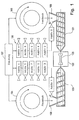
- FIG. 1 shows a plastic injection molding system with an injection molding unit 100 and an injection molding unit 101.
- the injection molding units 100 and 101 are on opposite sides Sides of an injection mold 102 are arranged.
- In the injection mold 102 there is at least one cavity for forming one or more Shapes 103.
- a material feed 104 is assigned to the injection molding unit 100.
- the material feed 104 is used to hold a base material for the production of Plastic moldings.
- the base material is, for example Polycarbonate or around polyamide with or without glass fiber content.
- the one with the basic material filled material feeder 104 is also referred to as a "feedstock”.
- a Corresponding material supply 105 is also assigned to the injection molding unit 101. This also includes a basic material.
- the plastic injection molding system also includes an additive feed 106
- Additive feed 106 is used to hold additives 0, 1, 2, ..., n-1, n.
- the material feeders 104 and 105 and the additive feeder 106 are included a controller 107. Furthermore, the controller 107 is - in FIG For the sake of clarity, line connections not shown - the injection molding units 100 and 101 and the injection mold 102.
- the procedure is as follows: The controller 107 activates the material feed 104 and selects it Additive 1 in the additive feeder 106. The base material from the material feeder 104 and additive 1 are then in the mixing device, which is below the Material feed 104 is arranged, mixed together and then the injection molding unit 100 fed.
- the controller 107 also closes the injection mold 102 and brings the injection molding unit 100 in one position for the injection molding process. Then the Production of one or more molded parts from the base material with the Additive 1. After molded parts from the base material with additive 1 in the desired Quantity can be produced without interrupting production can be switched to another base material with a different additive.
- controller 107 activates the material feed 105 and selects the or the desired additives of the additive feed 106.
- additive 0 was selected by controller 107.
- the basic material from the Material feed 105 and the selected additive 0 are then in a mixing device 109, which is arranged below the material feed 105, with one another mixed and fed to the injection molding unit 101.
- the controller 107 brings the injection molding unit 101 into a position for the injection molding process and closes the tool 102.
- the injection molding unit 100 During the production of the molded part or parts from the base material of the material feed 105 with the selected additive 0 is the injection molding unit 100 in a material change position.
- the controller 107 activates the material feed 104 and switches the addition of additives to the base material of the material feed 104 from.
- the injection molding unit 100 becomes base material from the material feed 104 fed without added additives.
- This plasticized base material flows through the injection molding unit 100 in the material change position, so that the Injection molding unit 100 cleaned from the additive of the previous injection molding process becomes. It is particularly advantageous here that the rinsing process of some Injection molding unit simultaneously with the injection molding process for the production of Plastic molded parts of the other injection molding unit can be made.
- plastic injection molding system for Small series production of customer-specific molded parts.
- Such small or small series can be efficiently with the plastic injection molding system of Figure 1 and produce economically, because during the ongoing production process can be switched to different material compositions.
- a particularly advantageous application of the plastic injection molding system Figure 1 is the production of test specimens, as used for testing material properties of polymers are needed.
- By appropriate control of the Plastic injection molding systems can be used to test specimens for various test formulations in quick succession and with relatively low cost and material expenditure produce. It should be emphasized in particular that the often expensive or only difficult to obtain additives targeted without shrinkage for the production of Test specimens are used.
- FIG. 2 shows a further preferred embodiment of the invention Kunststoffspritzg smartsystems.
- the plastic injection molding system of Figure 2 includes an injection molding unit 200 and an injection molding unit 201 which are on opposite sides Sides of an injection mold 202 are arranged.
- the injection mold 202 includes various forms for the production of molded parts, such as Test specimens. An embodiment of the injection mold 202 is shown below 3 are explained in more detail.
- plastic injection molding system 2 of the injection molding unit 200 and the injection molding unit 201 there are also in the plastic injection molding system 2 of the injection molding unit 200 and the injection molding unit 201 each assigned a material feed. There is also an additive feed available, as well as a process control for the plastic injection molding system. The Material feeds, additive feed and control are shown 2 not shown for the sake of clarity.
- the plastic injection molding system of Figure 2 also includes several reserve injection molding units 203 and 204 and corresponding waiting positions 205 and 206.
- Replacement injection molding units 207 are located in the waiting positions 205 and 206, respectively and 208.
- Exchange positions 209 and 210 are also provided. This are used to clean injection molding units.
- the injection molding unit 200 is in an injection molding operation for test specimen production. Especially with test formulations from which test specimens Cracking can occur more often because the Material properties of the test recipe are not yet exactly known.
- the injection molding unit 200 is in the exchange position 209 brought.
- the replacement injection molding unit 207 comes out of its waiting position 205 in the position for the injection molding process, that is, the test specimen production, brought.
- the replacement injection molding unit 207 is in its Waiting position 205 preheated so that the injection molding process continues immediately can be.
- the injection molding unit 200 in the exchange position 209 can then be cleaned, without the need to interrupt the manufacturing process. Furthermore, a Reserve injection molding unit 203 placed in the waiting position 205 to take the place the replacement injection molding unit 207 to kick. If cracking occurs again, then Proceed accordingly and the contaminated injection molding unit through the tracked Replacement injection molding unit replaced from the waiting position.
- the injection molding unit 201 is brought into the exchange position 210 and the replacement injection molding unit 208 is replaced from its waiting position 206 Injection molding unit 201 brought, so that the production essentially without interruption can continue to run.
- the injection molding unit 201 is in its exchange position 210 cleaned while a reserve injection molding unit 204 is in the waiting position 206 is tracked to the replacement injection molding unit removed from the waiting position 208 to replace.
- FIG. 3 shows an embodiment of the injection mold 202 from FIG. 2.
- Injection mold 202 includes molds 211, 212, 213, 214, 215 and 216.
- the molds 211, 212 and 213 are assigned to the injection molding unit 200 while the molds 214, 215 and 216 are assigned to the injection molding unit 201.
- the injection molding unit 200 is in the injection position for the test specimen production (see FIG. 2), while the injection molding unit 201 is in the material change position.
- the molds 211, 212 and 213 have channels 217 that face towards the injection molding unit 200 run.
- the channels 217 serve the plasticized polymer from the Injection molding unit 200 to be injected into the corresponding mold 211, 212 or 213.
- the forms 214, 215 and 216 have channels 218 which are for injection of the plasticized polymer from the injection molding unit 201 into the corresponding one Serve mold when the injection molding unit 201 is in the position for the Injection molding process.
- Injection mold 202 is electrically translational in directions 219 and 220 can be moved forward and backward. Arrangements are also possible where the displaceability is rotational.
- injection mold 202 placed in such a position that the channel 217 of the for the production of the molded part to be used mold of the injection molding unit 200 immediately is opposite. In the example case considered in FIG. 3, this is the case This is the form 212. Should be in a subsequent injection molding process a molded part with the shape 211 or 213 can be produced, so the injection mold is moved in the direction of 220 or in the direction of 219. The same applies to the forms 214, 215 and 216.
- FIG. 4 shows a flow diagram with regard to the control of the plastic injection molding system of Figures 1 and 2.
- the control of the plastic injection molding system is for example by a programmable process control unit (cf. control 107 of Figure 1) made.
- step 400 the injection molding unit A (cf. injection molding unit 100 of FIG Figure 1 and the injection molding unit 200 of Figure 2) in a position for the injection molding process brought.
- step 401 the injection molding unit A with base material mixed additive supplied.
- the basic material is made from the Injection molding unit A assigned material feed and taken with the selected Additive or the selected additives mixed.
- the polymer mixture consisting of base material and additive or additives is then plasticized in the injection molding unit A, so that in step 402 the production of test specimens.
- the position of the injection mold cf. injection mold 202 of Figure 3 varies accordingly.
- the injection molding unit A is moved to its material change position in step 403 to the Rinse injection molding unit A with base material.
- step 404 the injection molding unit B is brought into its material change position, after test specimens have previously been produced using the injection molding unit B. are.
- step 405 the injection molding unit B with base material from the Injection molding unit B rinsed material feed, the base material no additive is added. This flushing process takes place in step 406.
- the injection molding unit B is in its injection position in step 407 driven to start manufacturing test specimens.
- a test specimen is produced with the injection molding unit A.
- step 409 cracking occurs.
- step 410 the injection molding unit A is then in its cleaning position (see exchange position 209 of Figure 2) driven.
- step 411 a replacement injection molding unit placed in the place of injection molding unit A (see replacement injection molding unit 207 of Figure 2).
- step 412 the production of test specimens resumed.
- the injection molding unit is located parallel to steps 408 to 412 B in their material change position (see steps 404 to 406).
- sequence control described above is preferably carried out by a corresponding one Computer program for controlling the plastic injection system.
Landscapes
- Engineering & Computer Science (AREA)
- Manufacturing & Machinery (AREA)
- Mechanical Engineering (AREA)
- Injection Moulding Of Plastics Or The Like (AREA)
Abstract
Description
- Figur 1
- eine Prinzipdarstellung eines erfindungsgemäßen Kunststoffspritzgießsystems,
- Figur 2
- eine weitere Ausführungsform eines erfindungemäßen Kunststoffspritzgießsystems,
- Figur 3
- eine vergrößerte Darstellung des Spritzgießwerkzeugs des Kunststoffspritzgießsystems der Figur 2,
- Figur 4
- ein Flussdiagramm für die Ablaufsteuerung des Kunststoffspritzgießsystems der Figur 2.
- Spritzgießeinheit
- 100
- Spritzgießeinheit
- 101
- Spritzgießwerkzeug
- 102
- Form
- 103
- Materialzuführung
- 104
- Materialzuführung
- 105
- Additiv-Zuführung
- 106
- Steuerung
- 107
- Mischvorrichtung
- 108
- Mischvorrichtung
- 109
- Spritzgießeinheit
- 200
- Spritzgießeinheit
- 201
- Spritzgießwerkzeug
- 202
- Reserve-Spritzgießeinheit
- 203
- Reserve-Spritzgießeinheit
- 204
- Warteposition
- 205
- Warteposition
- 206
- Ersatz-Spritzgießeinheit
- 207
- Ersatz-Spritzgießeinheit
- 208
- Austauschposition
- 209
- Austauschposition
- 210
- Form
- 211
- Form
- 212
- Form
- 213
- Form
- 214
- Form
- 215
- Form
- 216
- Kanal
- 217
- Kanal
- 218
- Richtung
- 219
- Richtung
- 220
Claims (22)
- Verfahren zur Herstellung von Kunststoff-Formteilen mit folgenden Schritten:Herstellung eines ersten Formteils aus einem Grundmaterial mit einem ersten Additiv mittels einer ersten Spritzgießeinheit,Spülen einer zweiten Spritzgießeinheit mit dem Grundmaterial in einem Zeitraum während der Herstellung des ersten Formteils,Herstellung eines zweiten Formteils aus dem Grundmaterial mit einem zweiten Additiv mittels der zweiten Spritzgießeinheit.
- Verfahren nach Anspruch 1, wobei das Grundmaterial für die erste Spritzgießeinheit einer ersten Materialzuführung entnommen wird und das Grundmaterial für die zweite Spritzgießeinheit einer zweiten Materialzuführung entnommen wird, wobei die ersten und zweiten Materialzuführungen gesondert steuerbar sind.
- Verfahren nach Anspruch 1 oder 2, wobei zur Herstellung der ersten und zweiten Formteile ein Spritzgießwerkzeug mit einer ersten Form für das erste Formteil und einer zweiten Form für das zweite Formteil verwendet wird.
- Verfahren nach Anspruch 3, wobei die ersten und zweiten Spritzgießeinheiten an im Wesentlichen gegenüberliegenden Seiten des Spritzgießwerkzeugs angeordnet sind, und das Spritzgießwerkzeug zur Umstellung der Herstellung des ersten Formteils auf das zweite Formteil rotatorisch und/oder translatorisch bewegt wird.
- Verfahren nach Anspruch 4, wobei es sich bei der Bewegung um eine translatorische Bewegung im Wesentlichen senkrecht zu den Spritzgießeinheiten handelt.
- Verfahren nach einem der vorhergehenden Ansprüche 1 bis 5 mit folgenden weiteren Schritten:Vorheizen einer oder mehrerer erster und / oder zweiter Ersatz-Spritzgießeinheiten,Austausch der ersten oder zweiten Spritzgießeinheit, wenn bei einem Spritzgießvorgang ein Vercracken auftritt, gegen die erste bzw. die zweite Ersatz-Spritzgießeinheit.
- Verfahren nach Anspruch 6, wobei die erste oder zweite Spritzgießeinheit in eine Austauschposition zur Reinigung bewegt wird.
- Verfahren nach Anspruch 6 oder 7, wobei eine oder mehrere erste und/oder zweite Reserve-Spritzgießeinheiten zur Verfügung gestellt werden und eine der Reserve-Spritzgießeinheiten vorgeheizt wird, wenn eine Spritzgießeinheit durch eine Ersatz-Spritzgießeinheit ersetzt worden ist, so dass die Reserve-Spritzgießeinheit an die Stelle der betreffenden Ersatz-Spritzgießeinheit tritt.
- Verfahren nach einem der vorhergehenden Ansprüche 1 bis 8, wobei es sich bei den ersten und zweiten Formteilen um Prüfkörper handelt.
- Verfahren nach Anspruch 9, wobei das Spritzgießwerkzeug einen Satz erster Formen zur Herstellung von verschiedenen ersten Prüfkörpern und einen Satz zweiter Formen zur Herstellung von verschiedenen zweiten Prüfkörpern aufweist und wobei die Formen in dem Spritzgießwerkzeug im Wesentlichen senkrecht zu der Bewegungsrichtung des Spritzgießwerkzeugs angeordnet sind.
- Kunststoffspritzgießsystem miteiner ersten Spritzgießeinheit (100; 200) zur Herstellung eines ersten Formteils aus einem Grundmaterial mit einem ersten Additiv,einer zweiten Spritzgießeinheit (101; 201) zur Herstellung eines zweiten Formteils aus dem Grundmaterial mit einem zweiten Additiv,Mitteln (105) zum Spülen der zweiten Spritzgießeinheit mit dem Grundmaterial während der Herstellung des ersten Formteils mittels der ersten Spritzgießeinheit.
- Kunststoffspritzgießsystem nach Anspruch 11 mit einer ersten Materialzuführung (104) für das Grundmaterial für die erste Spritzgießeinheit und mit einer zweiten Materialzuführung (105) für das Grundmaterial für die zweite Spritzgießeinheit, wobei die ersten und zweiten Materialzuführungen gesondert steuerbar sind.
- Kunststoffspritzgießsystem nach Anspruch 12, wobei die erste und/oder die zweite Materialzuführung zur Spülung der zweiten Spritzgießeinheit mit dem Grundmaterial ausgebildet ist.
- Kunststoffspritzgießsystem nach einem der vorhergehenden Ansprüche 11 bis 13 mit einem Spritzgießwerkzeug (202) mit einer ersten Form (211, 212, 213) zur Herstellung des ersten Formteils und einer zweiten Form (214, 215, 216) zur Herstellung des zweiten Formteils.
- Kunststoffspritzgießsystem nach Anspruch 14, bei dem die ersten und zweiten Spritzgießeinheiten an gegenüberliegenden Seiten des Spritzgießwerkzeugs angeordnet sind und mit Mitteln zur rotatorischen und / oder translatorischen Bewegung des Spritzgießwerkzeugs zur Umstellung von der Herstellung des ersten Formteils auf das zweite Formteil.
- Kunststoffspritzgießsystem nach Anspruch 15, wobei die Mittel zur Bewegung zur translatorischen Bewegung (219, 220) des Spritzgießwerkzeugs in einer Richtung im Wesentlichen senkrecht zu den ersten und zweiten Spritzgießeinheiten ausgebildet ist.
- Kunststoffspritzgießsystem nach einem der vorhergehenden Ansprüche 11 bis 16 miteiner oder mehreren ersten und / oder zweiten Ersatz-Spritzgießeinheiten (205, 206),Mitteln zum Vorheizen der Ersatz-Spritzgießeinheit bzw. der Ersatz-Spritzgießeinheiten,Mitteln zum Austausch einer ersten oder zweiten Spritzgießeinheit durch eine erste bzw. zweite Ersatz-Spritzgießeinheit.
- Kunststoffspritzgießsystem nach Anspruch 17 mit Mitteln zur Bewegung der ersten und/oder zweiten Spritzgießeinheit in eine Austauschposition (209, 210).
- Kunststoffspritzgießsystem nach einem der vorhergehenden Ansprüche 11 bis 18 mit einer oder mehreren ersten und/oder zweiten Reserve-Spritzgießeinheiten (203, 204) und mit Mitteln zur Bewegung einer Reserve-Spritzgießeinheit in eine Position einer Ersatz-Spritzgießeinheit.
- Kunststoffspritzgießsystem nach einem der vorhergehenden Ansprüche 11 bis 19, wobei in dem Spritzgießwerkzeug erste Formen zur Herstellung von verschiedenen ersten Probekörpern und zweite Formen zur Herstellung von verschiedenen zweiten Probekörpern ausgebildet sind und die ersten und zweiten Formen im Wesentlichen senkrecht zu der Bewegungsrichtung des Spritzgießwerkzeugs angeordnet sind.
- Kunststoffspritzgießsystem nach einem der vorhergehenden Ansprüche 11 bis 20 mit Mitteln (106) zur Zuführung unterschiedlicher erster Additive zu dem Grundmaterial der ersten Materialzuführung und mit Mitteln (106) zur Zuführung verschiedener zweiter Additive zu dem Grundmaterial aus der zweiten Materialzuführung.
- Computerprogramm zur Steuerung eines Kunststoffspritzgießsystems nach einem Verfahren nach einem der vorhergehenden Ansprüche 1 bis 10.
Applications Claiming Priority (2)
| Application Number | Priority Date | Filing Date | Title |
|---|---|---|---|
| DE10156718 | 2001-11-19 | ||
| DE2001156718 DE10156718C1 (de) | 2001-11-19 | 2001-11-19 | Kunststoffspritzgießsystem und Verfahren zur Herstellung von Kunststoff-Formteilen |
Publications (2)
| Publication Number | Publication Date |
|---|---|
| EP1314530A1 true EP1314530A1 (de) | 2003-05-28 |
| EP1314530B1 EP1314530B1 (de) | 2005-10-05 |
Family
ID=7706223
Family Applications (1)
| Application Number | Title | Priority Date | Filing Date |
|---|---|---|---|
| EP20020024923 Expired - Lifetime EP1314530B1 (de) | 2001-11-19 | 2002-11-06 | Kunststoffspritzgiesssystem und Verfahren zur Herstellung von Kunststoff-Formteilen |
Country Status (2)
| Country | Link |
|---|---|
| EP (1) | EP1314530B1 (de) |
| DE (2) | DE10156718C1 (de) |
Families Citing this family (1)
| Publication number | Priority date | Publication date | Assignee | Title |
|---|---|---|---|---|
| CN112895305B (zh) * | 2021-01-22 | 2022-09-16 | 马鞍山康福塑料制品有限公司 | 一种防堵塞自清洁的注塑射胶设备 |
Citations (5)
| Publication number | Priority date | Publication date | Assignee | Title |
|---|---|---|---|---|
| JPS5714023A (en) * | 1980-06-30 | 1982-01-25 | Yamashiro Seiki Seisakusho:Kk | Multicylinder type injection molder |
| JPS5989130A (ja) * | 1982-11-15 | 1984-05-23 | Sumitomo Heavy Ind Ltd | スクリユシリンダユニツトの自動交換装置 |
| US4588365A (en) * | 1983-10-15 | 1986-05-13 | Battenfeld Maschinenfabriken Gmbh | Injection molding assembly |
| US5219586A (en) * | 1989-02-13 | 1993-06-15 | The Japan Steel Works Ltd. | Apparatus for both single and double injection molding |
| JPH05237866A (ja) * | 1992-02-28 | 1993-09-17 | Toyo Mach & Metal Co Ltd | 射出成形機 |
Family Cites Families (1)
| Publication number | Priority date | Publication date | Assignee | Title |
|---|---|---|---|---|
| DE4443153C2 (de) * | 1994-12-05 | 1997-10-16 | Bayer Ag | Verfahren zur Herstellung von Formkörpern aus Kunststofflegierungen |
-
2001
- 2001-11-19 DE DE2001156718 patent/DE10156718C1/de not_active Expired - Fee Related
-
2002
- 2002-11-06 DE DE50204454T patent/DE50204454D1/de not_active Expired - Lifetime
- 2002-11-06 EP EP20020024923 patent/EP1314530B1/de not_active Expired - Lifetime
Patent Citations (5)
| Publication number | Priority date | Publication date | Assignee | Title |
|---|---|---|---|---|
| JPS5714023A (en) * | 1980-06-30 | 1982-01-25 | Yamashiro Seiki Seisakusho:Kk | Multicylinder type injection molder |
| JPS5989130A (ja) * | 1982-11-15 | 1984-05-23 | Sumitomo Heavy Ind Ltd | スクリユシリンダユニツトの自動交換装置 |
| US4588365A (en) * | 1983-10-15 | 1986-05-13 | Battenfeld Maschinenfabriken Gmbh | Injection molding assembly |
| US5219586A (en) * | 1989-02-13 | 1993-06-15 | The Japan Steel Works Ltd. | Apparatus for both single and double injection molding |
| JPH05237866A (ja) * | 1992-02-28 | 1993-09-17 | Toyo Mach & Metal Co Ltd | 射出成形機 |
Non-Patent Citations (5)
| Title |
|---|
| "LEITRECHNER KOORDINIERT ALLE WECHSELVORGAENGE", PLASTVERARBEITER, ZECHNER UND HUETHIG VERLAG GMBH. SPEYER/RHEIN, DE, VOL. 41, NR. 4, PAGE(S) 142,144,146, ISSN: 0032-1338, XP000148452 * |
| JOHANNABER, MICHAELI: "Handbuch Spritzgiessen", 13 November 2001, CARL HANSER VERLAG, MÜNCHEN WIEN, XP002232673 * |
| PATENT ABSTRACTS OF JAPAN vol. 006, no. 074 (M - 127) 11 May 1982 (1982-05-11) * |
| PATENT ABSTRACTS OF JAPAN vol. 008, no. 201 (M - 325) 14 September 1984 (1984-09-14) * |
| PATENT ABSTRACTS OF JAPAN vol. 017, no. 694 (M - 1531) 17 December 1993 (1993-12-17) * |
Also Published As
| Publication number | Publication date |
|---|---|
| DE10156718C1 (de) | 2003-04-17 |
| EP1314530B1 (de) | 2005-10-05 |
| DE50204454D1 (de) | 2006-02-16 |
Similar Documents
| Publication | Publication Date | Title |
|---|---|---|
| DE19754863C2 (de) | Verfahren zur Herstellung unterschiedlich farbiger Pellets und Vorrichtung zur Durchführung des Verfahrens | |
| DE10141459C2 (de) | Verfahren und Vorrichtung zur Herstellung und Prüfung von Formkörpern | |
| AT11396U1 (de) | Verfahren zur herstellung einer verbund- oder hybridkonstruktion | |
| EP3450146B1 (de) | Applikationsvorrichtung und verfahren zum ausgeben eines formfaserverbundstrangs | |
| DD231029A1 (de) | Verfahren und einrichtung zum compoundieren von thermoplasten, insbesondere thermoplastabfaellen | |
| WO2001002471A1 (de) | Langfaserverstärktes thermoplastisches material und verfahren zum herstellen desselben | |
| DE102011083688A1 (de) | Formwerkzeug zum Herstellen von faserverstärkten Kunststoffbauteilen | |
| EP1810811B1 (de) | Verfahren und Vorrichtung zur Herstellung eines Formteils aus mindestens zwei unterschiedlichen Kunststoffen | |
| WO2010133641A2 (de) | Verfahren zur herstellung eines sic-keramik-bauteils | |
| DE202007018847U1 (de) | Vorrichtung zum Herstellen dickwandiger optischer Kunststoff-Formteile und dickwandiges optisches Kunststoff-Formteil | |
| EP3284567B1 (de) | Vorrichtung und verfahren zur herstellung einer gefärbten und einer ungefärbten kunststoffschmelze | |
| WO1998004853A1 (de) | Verfahren zur herstellung eines dichtelementes sowie dichtelement hergestellt nach dem verfahren | |
| DE102015116925A1 (de) | Verfahren und Vorrichtung zur Herstellung von Formteilen mit additiven und subtraktiven Fertigungsverfahren | |
| DE10156718C1 (de) | Kunststoffspritzgießsystem und Verfahren zur Herstellung von Kunststoff-Formteilen | |
| DE3324204A1 (de) | Verfahren und vorrichtung zum mindestens zweistufigen spritzgiessen von zusammengesetzten formkoerpern aus polymeren sowie anwendung des verfahrens | |
| WO2005051632A1 (de) | Formnestaufbau | |
| DE102007038671B4 (de) | Verfahren und Vorrichtung zur Herstellung von Prüfkörpern | |
| DE19908846A1 (de) | Verfahren zur Fertigung von Kunststofformteilen mit thermisch höher belasteten Segmenten | |
| DE60038461T2 (de) | Verbesserungen für spritzgiessformen | |
| EP4729270A1 (de) | Reinigung eines spritzgiesswerkzeuges | |
| WO2025087484A1 (de) | Verfahren zur herstellung eines formteils mittels kunststoffspritzgiessmaschine, formteil, einleger und spritzgiesswerkzeug zur durchführung des verfahrens | |
| DE102024127470A1 (de) | Spritzgussanlage und Verfahren zum Herstellen eines Mehrkomponenten-Spritzlings, Computerprogrammprodukt und Speichermedium | |
| DE102023125687A1 (de) | Gehäuseteil für ein elektrisches Gerät mit partiell amorpher Struktur und Verfahren zur Herstellung des Gehäuseteils | |
| DE102024131951A1 (de) | Reinigung eines Spritzgießwerkzeuges | |
| DE102023109494A1 (de) | Spritzgießwerkzeug, Reinigungverfahren für ein Spritzgießwerkzeug und Spritzgießverfahren |
Legal Events
| Date | Code | Title | Description |
|---|---|---|---|
| PUAI | Public reference made under article 153(3) epc to a published international application that has entered the european phase |
Free format text: ORIGINAL CODE: 0009012 |
|
| AK | Designated contracting states |
Designated state(s): AT BE BG CH CY CZ DE DK EE ES FI FR GB GR IE IT LI LU MC NL PT SE SK TR |
|
| AX | Request for extension of the european patent |
Extension state: AL LT LV MK RO SI |
|
| 17P | Request for examination filed |
Effective date: 20031128 |
|
| 17Q | First examination report despatched |
Effective date: 20040107 |
|
| AKX | Designation fees paid |
Designated state(s): CH DE FR LI NL |
|
| RAP1 | Party data changed (applicant data changed or rights of an application transferred) |
Owner name: BAYER MATERIALSCIENCE AG |
|
| GRAP | Despatch of communication of intention to grant a patent |
Free format text: ORIGINAL CODE: EPIDOSNIGR1 |
|
| RIN1 | Information on inventor provided before grant (corrected) |
Inventor name: SALEWSKI, KLAUS Inventor name: SARABI, BAHMAN, DR. |
|
| GRAS | Grant fee paid |
Free format text: ORIGINAL CODE: EPIDOSNIGR3 |
|
| GRAA | (expected) grant |
Free format text: ORIGINAL CODE: 0009210 |
|
| AK | Designated contracting states |
Kind code of ref document: B1 Designated state(s): CH DE FR LI NL |
|
| REG | Reference to a national code |
Ref country code: CH Ref legal event code: EP Ref country code: CH Ref legal event code: NV Representative=s name: E. BLUM & CO. PATENTANWAELTE |
|
| REF | Corresponds to: |
Ref document number: 50204454 Country of ref document: DE Date of ref document: 20060216 Kind code of ref document: P |
|
| ET | Fr: translation filed | ||
| PLBE | No opposition filed within time limit |
Free format text: ORIGINAL CODE: 0009261 |
|
| STAA | Information on the status of an ep patent application or granted ep patent |
Free format text: STATUS: NO OPPOSITION FILED WITHIN TIME LIMIT |
|
| 26N | No opposition filed |
Effective date: 20060706 |
|
| PGFP | Annual fee paid to national office [announced via postgrant information from national office to epo] |
Ref country code: FR Payment date: 20061108 Year of fee payment: 5 |
|
| PGFP | Annual fee paid to national office [announced via postgrant information from national office to epo] |
Ref country code: NL Payment date: 20061130 Year of fee payment: 5 |
|
| PGFP | Annual fee paid to national office [announced via postgrant information from national office to epo] |
Ref country code: CH Payment date: 20061206 Year of fee payment: 5 |
|
| REG | Reference to a national code |
Ref country code: CH Ref legal event code: PFA Owner name: BAYER MATERIALSCIENCE AG Free format text: BAYER MATERIALSCIENCE AG# #51368 LEVERKUSEN (DE) -TRANSFER TO- BAYER MATERIALSCIENCE AG# #51368 LEVERKUSEN (DE) |
|
| PG25 | Lapsed in a contracting state [announced via postgrant information from national office to epo] |
Ref country code: CH Free format text: LAPSE BECAUSE OF NON-PAYMENT OF DUE FEES Effective date: 20071130 Ref country code: LI Free format text: LAPSE BECAUSE OF NON-PAYMENT OF DUE FEES Effective date: 20071130 |
|
| REG | Reference to a national code |
Ref country code: CH Ref legal event code: PL |
|
| NLV4 | Nl: lapsed or anulled due to non-payment of the annual fee |
Effective date: 20080601 |
|
| PG25 | Lapsed in a contracting state [announced via postgrant information from national office to epo] |
Ref country code: NL Free format text: LAPSE BECAUSE OF NON-PAYMENT OF DUE FEES Effective date: 20080601 |
|
| REG | Reference to a national code |
Ref country code: FR Ref legal event code: ST Effective date: 20080930 |
|
| PG25 | Lapsed in a contracting state [announced via postgrant information from national office to epo] |
Ref country code: FR Free format text: LAPSE BECAUSE OF NON-PAYMENT OF DUE FEES Effective date: 20071130 |
|
| PGFP | Annual fee paid to national office [announced via postgrant information from national office to epo] |
Ref country code: DE Payment date: 20101109 Year of fee payment: 9 |
|
| REG | Reference to a national code |
Ref country code: DE Ref legal event code: R119 Ref document number: 50204454 Country of ref document: DE Effective date: 20120601 |
|
| PG25 | Lapsed in a contracting state [announced via postgrant information from national office to epo] |
Ref country code: DE Free format text: LAPSE BECAUSE OF NON-PAYMENT OF DUE FEES Effective date: 20120601 |