EP1314508A2 - Friction stir welding - Google Patents
Friction stir welding Download PDFInfo
- Publication number
- EP1314508A2 EP1314508A2 EP02257936A EP02257936A EP1314508A2 EP 1314508 A2 EP1314508 A2 EP 1314508A2 EP 02257936 A EP02257936 A EP 02257936A EP 02257936 A EP02257936 A EP 02257936A EP 1314508 A2 EP1314508 A2 EP 1314508A2
- Authority
- EP
- European Patent Office
- Prior art keywords
- welding
- works
- tack
- friction stir
- welded
- Prior art date
- Legal status (The legal status is an assumption and is not a legal conclusion. Google has not performed a legal analysis and makes no representation as to the accuracy of the status listed.)
- Granted
Links
Images


Classifications
-
- B—PERFORMING OPERATIONS; TRANSPORTING
- B23—MACHINE TOOLS; METAL-WORKING NOT OTHERWISE PROVIDED FOR
- B23K—SOLDERING OR UNSOLDERING; WELDING; CLADDING OR PLATING BY SOLDERING OR WELDING; CUTTING BY APPLYING HEAT LOCALLY, e.g. FLAME CUTTING; WORKING BY LASER BEAM
- B23K20/00—Non-electric welding by applying impact or other pressure, with or without the application of heat, e.g. cladding or plating
- B23K20/12—Non-electric welding by applying impact or other pressure, with or without the application of heat, e.g. cladding or plating the heat being generated by friction; Friction welding
- B23K20/122—Non-electric welding by applying impact or other pressure, with or without the application of heat, e.g. cladding or plating the heat being generated by friction; Friction welding using a non-consumable tool, e.g. friction stir welding
- B23K20/123—Controlling or monitoring the welding process
- B23K20/124—Controlling or monitoring the welding process at the beginning or at the end of a weld
-
- B—PERFORMING OPERATIONS; TRANSPORTING
- B23—MACHINE TOOLS; METAL-WORKING NOT OTHERWISE PROVIDED FOR
- B23K—SOLDERING OR UNSOLDERING; WELDING; CLADDING OR PLATING BY SOLDERING OR WELDING; CUTTING BY APPLYING HEAT LOCALLY, e.g. FLAME CUTTING; WORKING BY LASER BEAM
- B23K20/00—Non-electric welding by applying impact or other pressure, with or without the application of heat, e.g. cladding or plating
- B23K20/24—Preliminary treatment
-
- B—PERFORMING OPERATIONS; TRANSPORTING
- B23—MACHINE TOOLS; METAL-WORKING NOT OTHERWISE PROVIDED FOR
- B23K—SOLDERING OR UNSOLDERING; WELDING; CLADDING OR PLATING BY SOLDERING OR WELDING; CUTTING BY APPLYING HEAT LOCALLY, e.g. FLAME CUTTING; WORKING BY LASER BEAM
- B23K2101/00—Articles made by soldering, welding or cutting
- B23K2101/18—Sheet panels
Definitions
- the present invention relates to a method of welding a plurality of works by friction stir welding. More particularly, the present invention relates to a welding method optimal to welding of members constituting a structural body of a railway vehicle in manufacturing.
- structures constituting the vehicle body are formed by friction stir welding of a plurality of extruded sections.
- the extruded sections are arranged such that their longitudinal direction corresponds with the longitudinal direction of the vehicle body and their width conforms to the longitudinal periphery of the vehicle body.
- the works are placed to be butted along the longitudinal direction and the butted portion of the works is welded after being surface tack-welded at even intervals.
- the friction stir welding is continuously performed over the entire length of the butted portion including the tack-welded sections.
- the friction stir welding method is a solid phase welding method in which a rotating tool comprising a pin of a round bar shape to be inserted into the portion to be welded is rotated and moved along a joining line to cause the temperature of the portion to be welded to be increased by friction heat and the portion to be welded to thereby plastic flow.
- the works which go through the friction stir welding are comprised of members made of metal such as aluminium alloy suitable for friction stir welding.
- Japanese Laid-Open Patent Application Publication No. 2000 - 343250 discloses a method of manufacturing structures using a friction stir welding method.
- the portion to be welded is tack-welded at intervals over I-shaped grooves (instead of V-shaped grooves) and the friction stir welding is performed in the portions other than the tack-welded sections.
- the invention provides a friction stir welding method in which a plurality of works are placed to be butted, a plurality of V-shaped grooves are intermittently formed along a butted portion of the plurality of works, each of the V-shaped grooves is tack-welded by using a welding material, deposits in the tack-welded sections are cut and removed so as to be substantially coplanar with a surface of the plurality of works, and then the friction stir welding is continuously performed over the entire length of the butted portion
- the friction stir welding method since the tack welding is performed by the welding material being melted in the V-shaped grooves formed between the works, the welding strength at the tack-welded sections is increased and the tack-welding strength is increased in contrast with tack welding in which deposit welding is performed on a surface of the works.
- the portion of the tack-welded sections raised above the surface of the works is cut and removed so as to be substantially coplanar over the entire length of the butted portion, and in this state, the friction stir welding is performed by using a dedicated rotating tool. With this method, the friction stir welding is continuously performed without moving upwardly and downwardly the rotating tool over the entire length of the butted portion including the tack-welded sections, which facilitates welding work and increases work efficiency.
- the pin of the rotating tool is easily inserted into the butted portion to a sufficient depth and rotated. So, plastic flow occurs sufficiently from front surfaces of the works to a vicinity of their rear surfaces, and solid phase welding is performed there. Consequently, high welding strength is obtained. While the pin of the rotating tool is inserted into the tack-welded sections to a sufficient depth, the welded portions provided in the V-shaped grooves are not cut in contrast with the conventional deposit welding. Further, in the tack-welded sections, base metal of the works, together with the welding material being melted and solidified in the V-shaped grooves, is caused to plastic flow and to be solid-phase welded. Consequently, the friction stir welding is performed over the entire length of the butted portion including the tack-welded sections. Further, since the butted portion of the works is configured to be substantially coplanar over the entire length, finish is unnecessary after the friction stir welding.
- the tack-welding may, for example, be performed at intervals of approximately 400mm to 700mm.
- the intervals of the tack welding of the butted portion may be set to approximately 400mm to 700mm for the works as long as or longer than, for example, approximately 2000mm to 3000mm, the butted portion is not separated even when the deposits in the tack-welded sections are cut.
- the depth of the V-shaped grooves is approximately 30mm.
- the tack-welded sections may be cut and removed by using a grinding stone or a blade.
- a grinding stone or a blade By using the grinding stone or the blade, the cutting and removal can be performed relatively easily and in a short time, and finish after the cutting and removal is improved.
- the tack welding may be performed by MIG welding or TIG welding.
- metal having strength almost as high as that of the base metal of the works is preferably used as the welding material.
- the rotating tool (pin) causes the base metal of the works as well as the welded portion to plastic flow, and both of the materials are substantially uniformly mixed and solid-phase welded. Consequently, high welding strength can be obtained in the tack-welded sections as well as in the other butted portion.
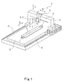
- a friction stir welding apparatus 1 comprises a flat bed 2 on which works to be joined comprised of two extruded sections, i.e., works k are placed, a gate-shaped frame 3 provided movably along a longitudinal direction of the bed 2, and a joint head 10 provided on a horizontal frame portion 4 of the gate-shaped frame 3 through a slider 5 such that the joint head 5 is movable in the lateral and vertical directions.
- the joint head 10 contains a motor (not shown) in an upper portion thereof, and rotatably supports a rotating tool 11 at a lower end portion thereof.
- the rotating tool 11 is integrally rotatably connected to a lower end of a drive shaft of the motor.
- the rotating tool 11 is conical and tapered downwardly.
- the rotating tool 11 is configured such that a cylindrical shoulder portion 11a is integrally formed at a tip end portion of the rotating tool 11 and a pin 11b is protruded from a center portion of a tip end face of the shoulder portion 11a.
- the shoulder portion 11a and the pin 11b are made of metal harder and more rigid than the material of the works k, for example, aluminium alloy, and their common center axis is inclined to an the opposite direction to the movement of the rotating tool 11 at an angle a (preferably about 3°) with respect to a vertical line.
- the gate-shaped frame 3 is movable along a pair of rails 6 provided on both sides of the bed 2.
- the rotating tool 11 provided on the gate-shaped frame 3 is adapted to move along a butted portion L (see Fig. 2) above a joining line of the butted portion L of the two works k.
- the friction stir welding apparatus 1 is constituted as described above and performs the friction stir welding as described below.
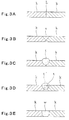
- the two works k are placed on the bed 2 along the longitudinal direction and fixed by means of a jig (not shown) such that longitudinal sections of the works k are butted with each other (see Fig. 3A).
- V-shaped grooves s each having a predetermined length (for example, approximately 30mm) are formed in the fixed two works k at predetermined intervals (for example, approximately 500mm) along the butted portion L (see Fig. 3B).
- the grooves s are formed by using a dedicated tool (not shown) relatively easily and in a short time.
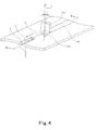
- two pairs of small tab plates j are respectively tack-welded with deposits m.
- the tab plates j are also butted with each other and the corresponding butted portion L' is tack-welded by deposits m (see Fig. 2) at certain intervals (see Fig. 2). That is, the two tab plates j are tack-welded by using I-shaped grooves.
- the V-shaped grooves s of the butted portion L in the works k are tack-welded by using a welding material comprised of aluminium alloy near to the material of the works k and by arc welding such as TIG welding or MIG welding.
- arc welding such as TIG welding or MIG welding.
- the welding material in the V-shaped grooves is melted and part t' of solidified welded portion t is raised above the surface of the works k and exposed (see Fig. 3C).
- the welded portion t' exposed above the works k from each of the V-shaped grooves s is cut and removed by using a cutting blade (not shown) and/or a grinder (not shown) to allow the surface of the butted portion L to be substantially coplanar over the entire length (see Fig. 3D).
- w denotes friction-stir-welded portion.
- the welding material is aluminium alloy near to the base metal of the works k
- the base metal of the works k and the welding material are caused to substantially uniformly plastic flow and to be solid-phase welded. Therefore, the high welding strength is obtained.
- the butted portion L of the works k is caused to be substantially coplanar over the entire length, finish after the friction stir welding is almost accomplished only by removing the tab plates j from the works k.
- hollow extruded sections may be used as the works k.
- three or more works may be butted and welded.
- a plurality of rotating tools 11 equal in number to the butted portions may be simultaneously used to perform friction stir welding of all the butted portions.
- the embodiments provide a friction stir welding method capable of welding a butted portion relatively easily and firmly after the butted portion is tack-welded and offering improved finish without a need for removal of deposits after the friction stir welding.
Landscapes
- Engineering & Computer Science (AREA)
- Mechanical Engineering (AREA)
- Pressure Welding/Diffusion-Bonding (AREA)
- Arc Welding In General (AREA)
Abstract
Description
Claims (5)
- A method of performing friction stir welding of a plurality of works (k) after performing tack welding of a butted portion (L) of the works (k) placed to be butted, the method comprising the steps of:forming a plurality of V-shaped grooves (s) intermittently along the butted portion (L) of the plurality of works (k) placed to be butted;performing tack welding of each of the V-shaped grooves (s) by using a welding material;cutting and removing deposits (m) in tack-welded sections (t) to be substantially coplanar with a surface of the works (k); andperforming friction stir welding of the butted portion (L) continuously over an entire length thereof.
- The method according to Claim 1, wherein the tack welding is performed at intervals of approximately 400mm to 700mm.
- The method according to Claim 1, wherein the deposits (m) in the tack-welded sections (t) are cut and removed by using a grinding stone or a cutting blade.
- The method according to Claim 1, 2 or 3, wherein the tack welding is performed by MIG welding or TIG welding, and metal having strength approximately as high as the strength of base metal of the works is used as the welding material.
- A method of friction butt welding a plurality of parts (k) disposed in abutting relationship, the method comprising providing recesses (s) in said works at spaced apart intervals along a weld line (L) between said parts, forming tack welds in said recesses, removing portions of said tack welds that protrude from said recesses and friction stir welding said parts continuously along said weld line.
Applications Claiming Priority (2)
| Application Number | Priority Date | Filing Date | Title |
|---|---|---|---|
| JP2001360682 | 2001-11-27 | ||
| JP2001360682A JP3510612B2 (en) | 2001-11-27 | 2001-11-27 | Friction stir welding method |
Publications (3)
| Publication Number | Publication Date |
|---|---|
| EP1314508A2 true EP1314508A2 (en) | 2003-05-28 |
| EP1314508A3 EP1314508A3 (en) | 2005-01-05 |
| EP1314508B1 EP1314508B1 (en) | 2011-01-26 |
Family
ID=19171454
Family Applications (1)
| Application Number | Title | Priority Date | Filing Date |
|---|---|---|---|
| EP02257936A Expired - Lifetime EP1314508B1 (en) | 2001-11-27 | 2002-11-18 | Method of friction stir welding |
Country Status (6)
| Country | Link |
|---|---|
| US (1) | US6715664B2 (en) |
| EP (1) | EP1314508B1 (en) |
| JP (1) | JP3510612B2 (en) |
| CN (1) | CN1192849C (en) |
| AT (1) | ATE496722T1 (en) |
| DE (1) | DE60239037D1 (en) |
Cited By (2)
| Publication number | Priority date | Publication date | Assignee | Title |
|---|---|---|---|---|
| TWI449585B (en) * | 2006-10-02 | 2014-08-21 | Nippon Light Metal Co | Bonding method |
| US20150290739A1 (en) * | 2011-08-19 | 2015-10-15 | Nippon Light Metal Company, Ltd. | Friction stir welding method |
Families Citing this family (60)
| Publication number | Priority date | Publication date | Assignee | Title |
|---|---|---|---|---|
| JP3761786B2 (en) * | 2001-01-17 | 2006-03-29 | 株式会社日立製作所 | Friction stir welding method and apparatus |
| US20030111514A1 (en) * | 2001-01-23 | 2003-06-19 | Naoki Miyanagi | Method of friction welding, and frictionally welded structure |
| JP4199446B2 (en) * | 2001-09-12 | 2008-12-17 | 株式会社日立製作所 | Friction stir welding equipment |
| US6908690B2 (en) * | 2002-04-29 | 2005-06-21 | The Boeing Company | Method and apparatus for friction stir welding |
| US6742697B2 (en) * | 2002-04-29 | 2004-06-01 | The Boeing Company | Joining of structural members by friction plug welding |
| JP3865686B2 (en) * | 2002-11-05 | 2007-01-10 | 住友軽金属工業株式会社 | Friction stir welding method and tab plate used therefor |
| FR2869249B1 (en) * | 2004-04-27 | 2007-06-29 | Snecma Moteurs Sa | FRICTION WELDING METHOD FOR BINDING A HOLE OF A METAL PIECE, METAL BAR, AND BEARING SUPPORT PART FOR CARRYING OUT THE PROCESS |
| US7078647B2 (en) * | 2004-10-21 | 2006-07-18 | Wisconsin Alumni Research Foundation | Arc-enhanced friction stir welding |
| KR100780019B1 (en) * | 2005-02-01 | 2007-11-27 | 가부시끼가이샤 히다치 세이사꾸쇼 | Friction Stir Welding |
| JP4751625B2 (en) * | 2005-03-03 | 2011-08-17 | 昭和電工株式会社 | Formation method of welded joint |
| US9511445B2 (en) | 2014-12-17 | 2016-12-06 | Aeroprobe Corporation | Solid state joining using additive friction stir processing |
| US9266191B2 (en) | 2013-12-18 | 2016-02-23 | Aeroprobe Corporation | Fabrication of monolithic stiffening ribs on metallic sheets |
| US8632850B2 (en) | 2005-09-26 | 2014-01-21 | Schultz-Creehan Holdings, Inc. | Friction fabrication tools |
| US9511446B2 (en) | 2014-12-17 | 2016-12-06 | Aeroprobe Corporation | In-situ interlocking of metals using additive friction stir processing |
| US8141768B2 (en) * | 2006-01-27 | 2012-03-27 | Exxonmobil Research And Engineering Company | Application of high integrity welding and repair of metal components in oil and gas exploration, production and refining |
| JP4873404B2 (en) | 2006-03-10 | 2012-02-08 | 国立大学法人大阪大学 | Metal processing method and structure |
| JP4844328B2 (en) * | 2006-10-02 | 2011-12-28 | 日本軽金属株式会社 | Joining method |
| JP4844329B2 (en) * | 2006-10-02 | 2011-12-28 | 日本軽金属株式会社 | Joining method |
| JP4957160B2 (en) * | 2006-10-02 | 2012-06-20 | 日本軽金属株式会社 | Joining method |
| JP5082364B2 (en) * | 2006-10-02 | 2012-11-28 | 日本軽金属株式会社 | Joining method |
| JP5092333B2 (en) * | 2006-10-02 | 2012-12-05 | 日本軽金属株式会社 | Joining method |
| WO2008132911A1 (en) * | 2007-04-17 | 2008-11-06 | Nippon Light Metal Company, Ltd. | Joining method |
| JP5194906B2 (en) * | 2007-04-17 | 2013-05-08 | 日本軽金属株式会社 | Joining method |
| CN101772395B (en) * | 2007-08-10 | 2013-01-16 | 日本轻金属株式会社 | Joining method and manufacturing method of joined structure |
| CN102794560B (en) * | 2007-08-10 | 2014-06-25 | 日本轻金属株式会社 | Joining method and method for manufacturing joined structure |
| DE102008054449A1 (en) * | 2007-12-19 | 2009-06-25 | Alstom Technology Ltd. | Method for connecting two conductor pieces |
| JP5223326B2 (en) * | 2007-12-21 | 2013-06-26 | 日本軽金属株式会社 | Joining method |
| JP5233557B2 (en) * | 2008-09-30 | 2013-07-10 | 日本軽金属株式会社 | Joining method |
| CN102837133B (en) * | 2007-12-21 | 2015-07-08 | 日本轻金属株式会社 | Joining method |
| WO2009104432A1 (en) * | 2008-02-18 | 2009-08-27 | 日本軽金属株式会社 | Jointing method |
| US20090261146A1 (en) * | 2008-03-25 | 2009-10-22 | Hou Gene J | Donor material technology for friction stir welding |
| US10843291B2 (en) * | 2008-11-15 | 2020-11-24 | The Boeing Company | Welding in preparation for superplastic forming |
| US7874471B2 (en) * | 2008-12-23 | 2011-01-25 | Exxonmobil Research And Engineering Company | Butt weld and method of making using fusion and friction stir welding |
| CN102085598B (en) * | 2009-12-03 | 2015-10-14 | 鸿富锦精密工业(深圳)有限公司 | Friction stirring connecting method |
| US9103358B2 (en) * | 2010-03-16 | 2015-08-11 | Eaton Corporation | Corrosion-resistant position measurement system and method of forming same |
| CN101850475B (en) * | 2010-04-29 | 2012-09-19 | 重庆大学 | Current loading method for current-carrying friction stir welding and equipment thereof |
| CN102120287B (en) * | 2010-12-16 | 2013-07-10 | 西安交通大学 | Embedded stirring and rubbing slit welding method |
| JP2012183565A (en) * | 2011-03-07 | 2012-09-27 | Suzuki Motor Corp | Friction stir welding method and welding jig |
| JP5338884B2 (en) * | 2011-11-07 | 2013-11-13 | 日本軽金属株式会社 | Joining method |
| JP5250123B1 (en) * | 2012-02-17 | 2013-07-31 | 株式会社日立製作所 | Method for manufacturing rotor coil for variable speed generator motor |
| EP2819804A1 (en) * | 2012-03-02 | 2015-01-07 | Megastir Technologies LLC | Friction bit joining of materials |
| JP5459339B2 (en) * | 2012-03-22 | 2014-04-02 | 日本軽金属株式会社 | Joining method |
| JP5338936B2 (en) * | 2012-03-22 | 2013-11-13 | 日本軽金属株式会社 | Joining method |
| JP6047951B2 (en) * | 2012-06-29 | 2016-12-21 | スズキ株式会社 | Friction stir welding method of metal material and metal material joined body |
| JP5338955B2 (en) * | 2012-07-19 | 2013-11-13 | 日本軽金属株式会社 | Joining method |
| US20140077668A1 (en) * | 2012-09-14 | 2014-03-20 | Apple Inc. | Friction stir welding parts including one or more expendable portions |
| CN104718045B (en) * | 2012-12-19 | 2017-09-15 | 三菱重工业株式会社 | The manufacture method and engagement fixture of grafting material |
| CA2921220C (en) * | 2013-08-13 | 2021-07-13 | Uacj Corporation | Friction stir welding method |
| JP6655868B2 (en) | 2014-08-28 | 2020-03-04 | 三菱重工エンジニアリング株式会社 | End tab for friction stir welding and method of manufacturing joining material |
| GB2540808A (en) * | 2015-07-29 | 2017-02-01 | Acergy France SAS | Repair of pipeline welds using friction stir processing |
| JP6172314B2 (en) * | 2016-03-01 | 2017-08-02 | 日本軽金属株式会社 | Joining method |
| US20170304933A1 (en) * | 2016-04-20 | 2017-10-26 | Brigham Young University | Friction stir additive processing and methods thereof |
| US10193424B2 (en) | 2016-09-28 | 2019-01-29 | Siemens Energy, Inc. | Method and system for welding rotor coils |
| CN106736329A (en) * | 2016-12-08 | 2017-05-31 | 京浜乐梦金属科技(苏州)有限公司 | Industrial cooling copper backboard manufacture method and friction-stir bonding machine |
| CN108687438B (en) * | 2017-04-12 | 2020-04-28 | 宁波江丰电子材料股份有限公司 | Back plate and manufacturing method thereof |
| US11446757B2 (en) | 2017-09-13 | 2022-09-20 | Jfe Steel Corporation | Double-sided friction stir welding method for metal sheets and double-sided friction stir welding device |
| AU2018359514C1 (en) | 2017-10-31 | 2021-05-27 | MELD Manufacturing Corporation | Solid-state additive manufacturing system and material compositions and structures |
| CN108581175A (en) * | 2018-04-24 | 2018-09-28 | 辽宁忠旺铝合金精深加工有限公司 | A kind of aluminum alloy stirring friction welding method with melting welding tack weld |
| CN112475647B (en) * | 2020-08-07 | 2021-12-17 | 兰州理工大学 | An assembly line method for arc welding and friction stir welding combined welding of thick metal plates |
| CN114932304A (en) * | 2022-04-28 | 2022-08-23 | 国营四达机械制造公司 | Friction stir welding repairing method for part hole side wall chipping defect |
Family Cites Families (11)
| Publication number | Priority date | Publication date | Assignee | Title |
|---|---|---|---|---|
| JP3333411B2 (en) * | 1996-12-18 | 2002-10-15 | 株式会社日立製作所 | Friction stir welding method and friction stir welding device |
| US6051325A (en) * | 1997-12-23 | 2000-04-18 | Mcdonnell Douglas Corporation | Joining of machined sandwich assemblies by friction stir welding |
| JP3296417B2 (en) * | 1997-12-24 | 2002-07-02 | 日本軽金属株式会社 | Friction stir welding method |
| US6230957B1 (en) * | 1998-03-06 | 2001-05-15 | Lockheed Martin Corporation | Method of using friction stir welding to repair weld defects and to help avoid weld defects in intersecting welds |
| JP3459198B2 (en) | 1999-05-31 | 2003-10-20 | 株式会社日立製作所 | How to make a structure |
| JP2000343245A (en) * | 1999-05-31 | 2000-12-12 | Hitachi Ltd | How to make a structure |
| JP3480913B2 (en) * | 1999-05-31 | 2003-12-22 | 株式会社日立製作所 | How to make a structure |
| JP3589930B2 (en) | 2000-02-25 | 2004-11-17 | 株式会社日立製作所 | Friction stir welding method |
| JP3763734B2 (en) * | 2000-10-27 | 2006-04-05 | 株式会社日立製作所 | Panel member processing method |
| JP3761786B2 (en) * | 2001-01-17 | 2006-03-29 | 株式会社日立製作所 | Friction stir welding method and apparatus |
| CN1421295A (en) * | 2001-11-27 | 2003-06-04 | 川崎重工业株式会社 | Rotary tool for friction stirring welding and friction stirring welding method and apparatus |
-
2001
- 2001-11-27 JP JP2001360682A patent/JP3510612B2/en not_active Expired - Fee Related
-
2002
- 2002-11-18 EP EP02257936A patent/EP1314508B1/en not_active Expired - Lifetime
- 2002-11-18 DE DE60239037T patent/DE60239037D1/en not_active Expired - Lifetime
- 2002-11-18 AT AT02257936T patent/ATE496722T1/en not_active IP Right Cessation
- 2002-11-20 CN CNB021527210A patent/CN1192849C/en not_active Expired - Fee Related
- 2002-11-25 US US10/304,545 patent/US6715664B2/en not_active Expired - Lifetime
Cited By (3)
| Publication number | Priority date | Publication date | Assignee | Title |
|---|---|---|---|---|
| TWI449585B (en) * | 2006-10-02 | 2014-08-21 | Nippon Light Metal Co | Bonding method |
| US20150290739A1 (en) * | 2011-08-19 | 2015-10-15 | Nippon Light Metal Company, Ltd. | Friction stir welding method |
| US9566661B2 (en) * | 2011-08-19 | 2017-02-14 | Nippon Light Metal Company, Ltd. | Friction stir welding method |
Also Published As
| Publication number | Publication date |
|---|---|
| US20030098336A1 (en) | 2003-05-29 |
| EP1314508B1 (en) | 2011-01-26 |
| ATE496722T1 (en) | 2011-02-15 |
| US6715664B2 (en) | 2004-04-06 |
| JP3510612B2 (en) | 2004-03-29 |
| CN1421294A (en) | 2003-06-04 |
| CN1192849C (en) | 2005-03-16 |
| EP1314508A3 (en) | 2005-01-05 |
| JP2003164980A (en) | 2003-06-10 |
| DE60239037D1 (en) | 2011-03-10 |
Similar Documents
| Publication | Publication Date | Title |
|---|---|---|
| EP1314508B1 (en) | Method of friction stir welding | |
| EP1314509A2 (en) | Friction stir welding | |
| US8393524B1 (en) | Counter-rotating spindle for friction stir welding | |
| US7281647B2 (en) | Friction stir weld repair | |
| US8763882B2 (en) | Friction stir welding method for metal material and metal material welded body obtained thereby | |
| JPS62282783A (en) | Connection method for metal strip and its device | |
| JP2004298896A (en) | Groove processing method and laser / arc combined welding method | |
| JP2008221294A (en) | Repair method and repair device for welded part | |
| JP2003164976A (en) | Rotary tool for friction stir welding, friction stir welding method using the same, and friction stir welding apparatus | |
| JP2011101891A (en) | Joining method | |
| JP3289650B2 (en) | Friction welding method | |
| JP4204680B2 (en) | Friction stir welding equipment | |
| JP2001300744A (en) | Friction stir welding method and friction stir welding tool | |
| JP4305888B2 (en) | Welding method for cylindrical members | |
| JP2004098124A (en) | Welding method and welding system | |
| JPH10305373A (en) | Seam welding method and apparatus | |
| JP5825997B2 (en) | Repair welding method for electroslag welding | |
| CN110325314A (en) | Joint method | |
| JP6756253B2 (en) | Joining method | |
| JP6794945B2 (en) | Joining method | |
| JP2003164977A (en) | Rotary tool for friction stir welding, friction stir welding method using the same, and friction stir welding apparatus | |
| JP2018176205A (en) | Bonding method | |
| JP2010005689A (en) | Tacking method of butting part in friction stir welding and friction stir welding method using the same | |
| JP2012143765A (en) | Laser welding method | |
| JP2001009572A (en) | Butt welding method and its welding apparatus |
Legal Events
| Date | Code | Title | Description |
|---|---|---|---|
| PUAI | Public reference made under article 153(3) epc to a published international application that has entered the european phase |
Free format text: ORIGINAL CODE: 0009012 |
|
| AK | Designated contracting states |
Designated state(s): AT BE BG CH CY CZ DE DK EE ES FI FR GB GR IE IT LI LU MC NL PT SE SK TR |
|
| AX | Request for extension of the european patent |
Extension state: AL LT LV MK RO SI |
|
| PUAL | Search report despatched |
Free format text: ORIGINAL CODE: 0009013 |
|
| AK | Designated contracting states |
Kind code of ref document: A3 Designated state(s): AT BE BG CH CY CZ DE DK EE ES FI FR GB GR IE IT LI LU MC NL PT SE SK TR |
|
| AX | Request for extension of the european patent |
Extension state: AL LT LV MK RO SI |
|
| 17P | Request for examination filed |
Effective date: 20050223 |
|
| AKX | Designation fees paid |
Designated state(s): AT BE BG CH CY CZ DE DK EE ES FI FR GB GR IE IT LI LU MC NL PT SE SK TR |
|
| 17Q | First examination report despatched |
Effective date: 20070613 |
|
| RTI1 | Title (correction) |
Free format text: METHOD OF FRICTION STIR WELDING |
|
| GRAP | Despatch of communication of intention to grant a patent |
Free format text: ORIGINAL CODE: EPIDOSNIGR1 |
|
| GRAS | Grant fee paid |
Free format text: ORIGINAL CODE: EPIDOSNIGR3 |
|
| GRAA | (expected) grant |
Free format text: ORIGINAL CODE: 0009210 |
|
| AK | Designated contracting states |
Kind code of ref document: B1 Designated state(s): AT BE BG CH CY CZ DE DK EE ES FI FR GB GR IE IT LI LU MC NL PT SE SK TR |
|
| REG | Reference to a national code |
Ref country code: GB Ref legal event code: FG4D |
|
| REG | Reference to a national code |
Ref country code: CH Ref legal event code: EP |
|
| REG | Reference to a national code |
Ref country code: IE Ref legal event code: FG4D |
|
| REF | Corresponds to: |
Ref document number: 60239037 Country of ref document: DE Date of ref document: 20110310 Kind code of ref document: P |
|
| REG | Reference to a national code |
Ref country code: DE Ref legal event code: R096 Ref document number: 60239037 Country of ref document: DE Effective date: 20110310 |
|
| REG | Reference to a national code |
Ref country code: SE Ref legal event code: TRGR |
|
| REG | Reference to a national code |
Ref country code: NL Ref legal event code: VDEP Effective date: 20110126 |
|
| PG25 | Lapsed in a contracting state [announced via postgrant information from national office to epo] |
Ref country code: GR Free format text: LAPSE BECAUSE OF FAILURE TO SUBMIT A TRANSLATION OF THE DESCRIPTION OR TO PAY THE FEE WITHIN THE PRESCRIBED TIME-LIMIT Effective date: 20110427 Ref country code: PT Free format text: LAPSE BECAUSE OF FAILURE TO SUBMIT A TRANSLATION OF THE DESCRIPTION OR TO PAY THE FEE WITHIN THE PRESCRIBED TIME-LIMIT Effective date: 20110526 Ref country code: ES Free format text: LAPSE BECAUSE OF FAILURE TO SUBMIT A TRANSLATION OF THE DESCRIPTION OR TO PAY THE FEE WITHIN THE PRESCRIBED TIME-LIMIT Effective date: 20110507 |
|
| PG25 | Lapsed in a contracting state [announced via postgrant information from national office to epo] |
Ref country code: BE Free format text: LAPSE BECAUSE OF FAILURE TO SUBMIT A TRANSLATION OF THE DESCRIPTION OR TO PAY THE FEE WITHIN THE PRESCRIBED TIME-LIMIT Effective date: 20110126 Ref country code: FI Free format text: LAPSE BECAUSE OF FAILURE TO SUBMIT A TRANSLATION OF THE DESCRIPTION OR TO PAY THE FEE WITHIN THE PRESCRIBED TIME-LIMIT Effective date: 20110126 Ref country code: CY Free format text: LAPSE BECAUSE OF FAILURE TO SUBMIT A TRANSLATION OF THE DESCRIPTION OR TO PAY THE FEE WITHIN THE PRESCRIBED TIME-LIMIT Effective date: 20110126 Ref country code: AT Free format text: LAPSE BECAUSE OF FAILURE TO SUBMIT A TRANSLATION OF THE DESCRIPTION OR TO PAY THE FEE WITHIN THE PRESCRIBED TIME-LIMIT Effective date: 20110126 Ref country code: BG Free format text: LAPSE BECAUSE OF FAILURE TO SUBMIT A TRANSLATION OF THE DESCRIPTION OR TO PAY THE FEE WITHIN THE PRESCRIBED TIME-LIMIT Effective date: 20110426 Ref country code: NL Free format text: LAPSE BECAUSE OF FAILURE TO SUBMIT A TRANSLATION OF THE DESCRIPTION OR TO PAY THE FEE WITHIN THE PRESCRIBED TIME-LIMIT Effective date: 20110126 |
|
| PG25 | Lapsed in a contracting state [announced via postgrant information from national office to epo] |
Ref country code: DK Free format text: LAPSE BECAUSE OF FAILURE TO SUBMIT A TRANSLATION OF THE DESCRIPTION OR TO PAY THE FEE WITHIN THE PRESCRIBED TIME-LIMIT Effective date: 20110126 Ref country code: EE Free format text: LAPSE BECAUSE OF FAILURE TO SUBMIT A TRANSLATION OF THE DESCRIPTION OR TO PAY THE FEE WITHIN THE PRESCRIBED TIME-LIMIT Effective date: 20110126 |
|
| PG25 | Lapsed in a contracting state [announced via postgrant information from national office to epo] |
Ref country code: SK Free format text: LAPSE BECAUSE OF FAILURE TO SUBMIT A TRANSLATION OF THE DESCRIPTION OR TO PAY THE FEE WITHIN THE PRESCRIBED TIME-LIMIT Effective date: 20110126 Ref country code: CZ Free format text: LAPSE BECAUSE OF FAILURE TO SUBMIT A TRANSLATION OF THE DESCRIPTION OR TO PAY THE FEE WITHIN THE PRESCRIBED TIME-LIMIT Effective date: 20110126 |
|
| PLBE | No opposition filed within time limit |
Free format text: ORIGINAL CODE: 0009261 |
|
| STAA | Information on the status of an ep patent application or granted ep patent |
Free format text: STATUS: NO OPPOSITION FILED WITHIN TIME LIMIT |
|
| 26N | No opposition filed |
Effective date: 20111027 |
|
| REG | Reference to a national code |
Ref country code: DE Ref legal event code: R097 Ref document number: 60239037 Country of ref document: DE Effective date: 20111027 |
|
| PG25 | Lapsed in a contracting state [announced via postgrant information from national office to epo] |
Ref country code: IT Free format text: LAPSE BECAUSE OF FAILURE TO SUBMIT A TRANSLATION OF THE DESCRIPTION OR TO PAY THE FEE WITHIN THE PRESCRIBED TIME-LIMIT Effective date: 20110126 |
|
| PG25 | Lapsed in a contracting state [announced via postgrant information from national office to epo] |
Ref country code: MC Free format text: LAPSE BECAUSE OF NON-PAYMENT OF DUE FEES Effective date: 20111130 |
|
| REG | Reference to a national code |
Ref country code: CH Ref legal event code: PL |
|
| PG25 | Lapsed in a contracting state [announced via postgrant information from national office to epo] |
Ref country code: LI Free format text: LAPSE BECAUSE OF NON-PAYMENT OF DUE FEES Effective date: 20111130 Ref country code: CH Free format text: LAPSE BECAUSE OF NON-PAYMENT OF DUE FEES Effective date: 20111130 |
|
| REG | Reference to a national code |
Ref country code: IE Ref legal event code: MM4A |
|
| PG25 | Lapsed in a contracting state [announced via postgrant information from national office to epo] |
Ref country code: IE Free format text: LAPSE BECAUSE OF NON-PAYMENT OF DUE FEES Effective date: 20111118 |
|
| PG25 | Lapsed in a contracting state [announced via postgrant information from national office to epo] |
Ref country code: LU Free format text: LAPSE BECAUSE OF NON-PAYMENT OF DUE FEES Effective date: 20111118 |
|
| PG25 | Lapsed in a contracting state [announced via postgrant information from national office to epo] |
Ref country code: TR Free format text: LAPSE BECAUSE OF FAILURE TO SUBMIT A TRANSLATION OF THE DESCRIPTION OR TO PAY THE FEE WITHIN THE PRESCRIBED TIME-LIMIT Effective date: 20110126 |
|
| REG | Reference to a national code |
Ref country code: FR Ref legal event code: PLFP Year of fee payment: 14 |
|
| REG | Reference to a national code |
Ref country code: FR Ref legal event code: PLFP Year of fee payment: 15 |
|
| REG | Reference to a national code |
Ref country code: FR Ref legal event code: PLFP Year of fee payment: 16 |
|
| REG | Reference to a national code |
Ref country code: FR Ref legal event code: PLFP Year of fee payment: 17 |
|
| PGFP | Annual fee paid to national office [announced via postgrant information from national office to epo] |
Ref country code: SE Payment date: 20181113 Year of fee payment: 17 Ref country code: DE Payment date: 20181106 Year of fee payment: 17 |
|
| PGFP | Annual fee paid to national office [announced via postgrant information from national office to epo] |
Ref country code: FR Payment date: 20181011 Year of fee payment: 17 Ref country code: GB Payment date: 20181114 Year of fee payment: 17 |
|
| REG | Reference to a national code |
Ref country code: DE Ref legal event code: R119 Ref document number: 60239037 Country of ref document: DE |
|
| REG | Reference to a national code |
Ref country code: SE Ref legal event code: EUG |
|
| PG25 | Lapsed in a contracting state [announced via postgrant information from national office to epo] |
Ref country code: SE Free format text: LAPSE BECAUSE OF NON-PAYMENT OF DUE FEES Effective date: 20191119 |
|
| GBPC | Gb: european patent ceased through non-payment of renewal fee |
Effective date: 20191118 |
|
| PG25 | Lapsed in a contracting state [announced via postgrant information from national office to epo] |
Ref country code: DE Free format text: LAPSE BECAUSE OF NON-PAYMENT OF DUE FEES Effective date: 20200603 Ref country code: GB Free format text: LAPSE BECAUSE OF NON-PAYMENT OF DUE FEES Effective date: 20191118 Ref country code: FR Free format text: LAPSE BECAUSE OF NON-PAYMENT OF DUE FEES Effective date: 20191130 |