EP1314382A1 - Electronic labelling system to be carried by the cross member of a peg hook display device - Google Patents
Electronic labelling system to be carried by the cross member of a peg hook display device Download PDFInfo
- Publication number
- EP1314382A1 EP1314382A1 EP02292894A EP02292894A EP1314382A1 EP 1314382 A1 EP1314382 A1 EP 1314382A1 EP 02292894 A EP02292894 A EP 02292894A EP 02292894 A EP02292894 A EP 02292894A EP 1314382 A1 EP1314382 A1 EP 1314382A1
- Authority
- EP
- European Patent Office
- Prior art keywords
- housing
- label
- labeling system
- suspension element
- upper wing
- Prior art date
- Legal status (The legal status is an assumption and is not a legal conclusion. Google has not performed a legal analysis and makes no representation as to the accuracy of the status listed.)
- Granted
Links
Images

Classifications
-
- G—PHYSICS
- G09—EDUCATION; CRYPTOGRAPHY; DISPLAY; ADVERTISING; SEALS
- G09F—DISPLAYING; ADVERTISING; SIGNS; LABELS OR NAME-PLATES; SEALS
- G09F3/00—Labels, tag tickets, or similar identification or indication means; Seals; Postage or like stamps
- G09F3/08—Fastening or securing by means not forming part of the material of the label itself
- G09F3/18—Casings, frames or enclosures for labels
- G09F3/20—Casings, frames or enclosures for labels for adjustable, removable, or interchangeable labels
- G09F3/204—Casings, frames or enclosures for labels for adjustable, removable, or interchangeable labels specially adapted to be attached to a shelf or the like
-
- A—HUMAN NECESSITIES
- A47—FURNITURE; DOMESTIC ARTICLES OR APPLIANCES; COFFEE MILLS; SPICE MILLS; SUCTION CLEANERS IN GENERAL
- A47F—SPECIAL FURNITURE, FITTINGS, OR ACCESSORIES FOR SHOPS, STOREHOUSES, BARS, RESTAURANTS OR THE LIKE; PAYING COUNTERS
- A47F5/00—Show stands, hangers, or shelves characterised by their constructional features
- A47F5/08—Show stands, hangers, or shelves characterised by their constructional features secured to the wall, ceiling, or the like; Wall-bracket display devices
- A47F5/0807—Display panels, grids or rods used for suspending merchandise or cards supporting articles; Movable brackets therefor
- A47F5/0869—Accessories for article-supporting brackets, e.g. price- indicating means, not covered by a single one of groups A47F5/08
-
- G—PHYSICS
- G09—EDUCATION; CRYPTOGRAPHY; DISPLAY; ADVERTISING; SEALS
- G09F—DISPLAYING; ADVERTISING; SIGNS; LABELS OR NAME-PLATES; SEALS
- G09F3/00—Labels, tag tickets, or similar identification or indication means; Seals; Postage or like stamps
- G09F3/08—Fastening or securing by means not forming part of the material of the label itself
- G09F3/18—Casings, frames or enclosures for labels
- G09F3/20—Casings, frames or enclosures for labels for adjustable, removable, or interchangeable labels
- G09F3/208—Electronic labels, Labels integrating electronic displays
Definitions
- the present invention relates generally to a system electronic labeling.
- the stickers electronics are usually in the form of a box, generally fairly flat rectangular parallelepiped, on the front side of which is arranged a display element such as a display screen with liquid crystals.
- the display is controlled by a microprocessor, by example remotely controlled by the store's central computer.
- the label and the rail include means ensuring a setting label place by snap in the rail which are such that well that it is easy to put the label in the rail, it is impossible to move said label along the rail or to extract it from said rail if one does not have the right tool.
- These means consist, on the one hand, of grooves longitudinal formed in two wings of the rail arranged opposite and between which the label must be positioned, and on the other hand by a rib formed on one side of the label intended to be engaged in the longitudinal groove of one of the wings of the rail, and a retractable finger biased by elastic means, mounted projecting on the opposite side of the label and intended to be engaged in the longitudinal groove of the other rail wing.
- This arrangement provides a labeling system electronic which is very simple to implement and which ensures that the label cannot be moved along the rail to be facing products other than those whose characteristics it carries, or be stolen by more or less malicious people.
- Document US 6,126,125 discloses a hanging device for attaching electronic labels to the shelves of a storage warehouse.
- the hanging device is formed of a single part comprising a rail intended to receive said label and a coupling element intended to allow the fixing of the label on the underside of the shelf.
- the hanging device protects the electronic tag and is able to unhook from the shelf in case of shock, when the shelves are moved by an elevator.
- WO-97/48862 describes a label holder electronic allowing to fix an electronic label on a display comprising a rod.
- This support consists of a body intended to receive the electronic label and an adapter intended for securely fix the body to a frame part.
- the body is fixed to the adapter by means of clips.
- the display rod is specially modified to include the frame part receiving the adapter.
- the aim of the present invention is to propose a system labeling using the same labels not for products displayed on shelves, but for products packed in plastic film and carried by a pin display.
- Said system labeling is suitable for most of the forms that said can take spindle and in particular when said spindle has a T-rod.
- the product packaging has an opening thanks to which it is threaded on the spindle arranged perpendicular to a fixed wall.
- a rod terminated at its front end by a cross that is perpendicular to it.
- the label is attached to this crosspiece so that it can be rotated around it when removing or placing products carried by the spindle
- the following labeling system the invention intended for products carried by a pin display 1, is consists of an electronic label 2, a box 3 and an element of suspension 4.
- the pin display 1 shown in the drawing includes a pin 10 on which the product packaging will be threaded offered for sale and a rod 11 extending parallel to the pin 10, above the latter.
- a cross member 12 is fixed to the end of the rod 11 and perpendicular thereto.
- the invention applies well heard on any form of pin display, these comprising always whatever their embodiment the elements described above.
- the cross member 12 instead of being fixed in its middle to the rod 11, can be an integral part of said rod 11 and be obtained by folding the end thereof, with formation of a stop means at its free end so that the suspension element 4 cannot be removed by sliding it along the cross.
- Label 2 is similar to that described in the prior patent of the plaintiff cited above. It comes in the form of a flat rectangular parallelepiped body with the front face 26 formed by one of the large faces is equipped with a display screen 27, by liquid crystal example.
- a retractable finger 24 forming a first attachment means is mounted in the body of the label and protrudes by the upper face 21 thereof being pushed back by a non-spring shown in the drawing.
- a longitudinal groove 23 forming a second hooking means is formed in the underside 22, substantially in the middle of it.
- the body of the label 2 still has a blind hole 25 formed in the rear face 28.
- Box 3 is an open box with a generally C-shaped section and is consisting of a bottom 37 and two wings 31, 32 extending perpendicular to said bottom 37, at the top and bottom thereof.
- the front ends of the wings 31, 32 have oblique surfaces 38 moving away from each other as they move away from the bottom 37 of the housing 3.
- the lower wing 32 has a longitudinal rib 33 formed in its internal surface facing the upper wing 31.
- the upper wing 31 has a longitudinal groove 34 formed in its internal surface facing the lower wing 32.
- the upper wing 31 also has a slot 39 opening out. in a recess 36 formed in the bottom 37 of the housing 3.
- a pin 35 is formed on the bottom of the recess 36. Said pin 35 is of length greater than the depth of said recess 36 so that its end protrudes towards the front of the bottom 37 of the housing 3.
- Each of the walls 41 and 42 is crossed by an orifice opening 45, the two orifices 45 being axially aligned.
- the housing 3 is of such dimensions that the label 2 can be introduced between the wings 31 and 32 thereof.
- the suspension element 4 is intended to be placed astride the cross 12 of the pin display 1.
- it is produced in a material having a certain flexibility, for example a material rigid plastic sheet, so that the walls 41, 42 can be separated from each other.
- the walls 41, 42 are separated from one another in order to position the two parts of the wall 41 on one side of the cross member 12 and on either side of the rod 11 and the wall 42 on the other side of the cross 12.
- the suspension element 4 is then moved perpendicular to cross member 12 until it is positioned in the portion cylindrical 43.
- the suspension element 4 is placed on the cross 12 as described above, then the housing 3 is placed on said suspension element 4. To do this, the housing 3 is moved relatively to said suspension element 4 so that the walls 41, 42 of the latter slide in the slot 39 and in the recess 36. A angular displacement of the housing 3 relative to the suspension element 4 allows the walls 41, 42 to pass over the pin 35 until the orifices 45 of the walls 41, 42 can be positioned around of said pin 35.
- the depth of the recess 36 is preferably equal to the sum of the thicknesses of the two walls 41 and 42 of the element of suspension 4, so that, after installation of the housing 3 on the suspension element 4 as described above, the latter is at flower with the front face of the bottom 27 of the housing 3.
- the label 2 is then placed in the support 3.
- label 2 is presented inclined forward in order to position the groove 23 on its underside 22 against the rib 33 of the lower wing 32 of said housing 3, this position being made possible by the oblique surface 38 of the wing 32.
- a rotational movement around said rib 33 brings the label 2 of the bottom 37 of the housing 3.
- the finger 24 is brought to the contact of the oblique surface 38 of the upper wing 31, it is pushed back towards the inside of the body of the label 2.
- the finger 24 is disposed opposite the groove 34 of the upper wing 31 and can resume its initial position.
- the pin 35, the blind hole 25 of the label and the holes 45 of the suspension element 4 then constitute means of positioning which, in combination with the first 24 and second 23 attachment means carried by the body of the label 2 and the means corresponding upper 31 and lower 32 wings of the housing 3, ensure the relative positioning and retention of the three elements of the labeling system according to the invention: the suspension element 4, the housing 3 and the label 2.
- These means are advantageously inaccessible when the label 2 is positioned in the case 3 in order to avoid any malicious dismantling of the system.
- This provides a secure mounting that cannot be separated without a specially adapted tool.
- the label 2 can only be removed from the housing 3 when using a tool suitable with magnetic means for recalling finger 24 inward of the label body.
- the part of the suspension element 4 which protrudes above the upper wing 31 of the housing 3 and the part of the central notch 46 which extends into the wall 42 of said suspension element 4 are of dimensions such that the suspension element 4 can be rotated around the cross member 12 without this movement being hampered by the end of the rod 11, by the suspension element 4 or by the housing 3 in order to free up the space required below the rod 11 for position or remove items from the spindle 10.
- Figures 2 to 4 show three embodiments allowing to position the front face of the label according to inclinations different.
- the display screen 27 being constituted by a liquid crystal display, the reading axis must be generally perpendicular to the screen surface. It is therefore appropriate that labels positioned on displays located at medium height have their front face arranged substantially vertically while those located on display stands at high or very low height have their front face inclined respectively downwards or towards the top.
- the suspension element 5, 6, 7 is produced with a general L-shape, its cylindrical portion 53, 63, 73 being disposed at the free end of the small branch of L.
- the walls of the suspension elements 5, 6, 7 are folded substantially at right angles to present a small portion 50, 60, 70 and a large portion 51, 61, 71 disposed substantially perpendicular to the small portion and tiné to be inserted in the housing 3.
- the suspension element 5 in FIG. 2 has a small portion 50 of relatively large length. When this one is positioned behind the cross member 12 as shown, label 2 is strongly tilted upwards. A suspension element with a such a small portion 50 of relatively large length positioned at the front of the cross, would allow to obtain a mounting with the label 2 strongly tilted down.
- the suspension element 6 of Figure 3 has a small portion 60 of medium length. When this is positioned at front of cross member 12 as shown, label 2 is moderately inclined downwards. A suspension element with a such a small portion 60 of medium length positioned at the front of the crosspiece, would allow an assembly with the label 2 moderately tilted upwards.
- the suspension element 7 in FIG. 4 has a small portion 70 of short length, equivalent to about half of the thickness of the housing 3. When the latter is positioned at the rear of the cross 12 as shown, the label 2 is vertical. So would even with a suspension element whose small portion 70 of weak length, roughly half the thickness of the case 3 would be positioned at the front of the sleeper.
- the suspension element may not have notch. It would then be possible to position the pin 35 of the housing 3, the blind hole 25 of the label 2 and the orifices 45 of the element of longitudinally suspended in the center of these so that said suspension element could be placed with either of its walls at the front of said cross member 12. This arrangement would especially advantageous for suspension elements having folded walls substantially at right angles as they could be placed either for elements placed in height or for elements s placed low enough.
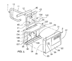
- FIG. 5 shows a second preferred embodiment of the attachment system according to the invention.
- the first means for attaching the electronic label 2 consisting of the finger retractable 24
- a corresponding means which is a hole blind 134.
- This blind hole is made in the upper wing 131 of the housing 103 and opens onto the face of the upper wing 131 opposite the lower wing 32.
- the retractable finger 24 made of metal and almost unbreakable, positioned in blind hole 134 prevents, during an impact significant lateral, any rupture of the plastic pin 35.
- a groove 138 is made between said blind hole 134 and the front face of the upper wing 131.
- the surface of the bottom of the groove 138 is inclined and forms a ramp guide for the retractable finger 24.
- THE guide ramp opens laterally in the blind hole 134 between the bottom of the blind hole and the surface of the upper wing 131. This particular arrangement allows the retractable finger 24 to cross the front face of the upper wing 131 and to snap into blind hole 134.
- the lateral faces of the groove 138 are get closer to each other as they get closer to the bottom 137 or the blind hole 134 of the housing 103.
- This arrangement has the advantage of guide the retractable finger 24 when placing the label on the support and therefore allow the label to be placed correctly electronics 2 laterally relative to support 103.
- the user can easily find the lateral position such as the pin 35 actually enters the blind hole 25 provided in the rear fa of label 2.
- a second pawn 135 is formed on the bottom of the recess 36.
- the second pawn 135 is of length substantially equal to the depth of said obviously 36.
- said second pawn is placed symmetrically with respect to the pin 35 relative to a vertical plane of symmetry passing through the center of the housing 103.
- each of the walls 41 and 42 of the suspension element 104, of the second embodiment, is crossed by a second orifice opening 145, the two second orifices being axially aligned.
- the orifices 145 and 45 being preferably placed symmetrically relatively to a vertical plane of symmetry passing through the center of the suspension element 104.
- the walls 41 and 42 pass above the pin 35, and therefore the second pin 135 shorter, until the holes 45 of the walls 41 and 42 can be positioned around said pin 35 and that the orifices 145 of the walls 41 and 42 can be positioned around said second pin 135.
- This particular arrangement of the second embodiment of the present invention makes it possible to stiffen the connection between, on the one hand, the assembly constituted by the housing 103 and the electronic label 2 and, on the other hand, the suspension element 104, made of a material plastic, by folding plastic sheets or by plastic injection in a mold, having a certain flexibility and therefore an ability to the deformation. In particular, this prevents the suspension element 104 does not deform and turns around the pad 35 of the housing.
- This second pawn 135, forming a second attachment point for the fastening element is particularly interesting when the suspension element used is the suspension element 5 of FIG. 2 comprising a portion 50 of relatively large length.
Landscapes
- Physics & Mathematics (AREA)
- General Physics & Mathematics (AREA)
- Engineering & Computer Science (AREA)
- Theoretical Computer Science (AREA)
- Labeling Devices (AREA)
- Details Of Rigid Or Semi-Rigid Containers (AREA)
- Devices For Indicating Variable Information By Combining Individual Elements (AREA)
- Package Frames And Binding Bands (AREA)
- Illuminated Signs And Luminous Advertising (AREA)
- Catching Or Destruction (AREA)
- Telephone Function (AREA)
- Tests Of Electronic Circuits (AREA)
Abstract
Description
La présente invention concerne d'une manière générale un système d'étiquetage électronique.The present invention relates generally to a system electronic labeling.
L'étiquetage électronique se répand actuellement dans les magasins, notamment dans les grands magasins. Les étiquettes électroniques se présentent usuellement sous la forme d'un boítier, généralement parallélépipèdique rectangle assez plat, sur la face avant duquel est disposé un élément d'affichage tel qu'un écran d'affichage à cristaux liquides. L'affichage est commandé par un microprocesseur, par exemple piloté à distance par l'ordinateur central du magasin.Electronic labeling is currently spreading in stores, especially in department stores. The stickers electronics are usually in the form of a box, generally fairly flat rectangular parallelepiped, on the front side of which is arranged a display element such as a display screen with liquid crystals. The display is controlled by a microprocessor, by example remotely controlled by the store's central computer.
Il est déjà connu par exemple par la demande internationale publiée sous le N° WO-98/58360 une telle étiquette électronique et un rail permettant le positionnement de celle -ci sur le bord avant des étagères de gondoles sur lesquelles sont disposés les produits offerts à la vente.It is already known for example by international demand published under No. WO-98/58360 such an electronic label and a rail for positioning it on the front edge of the shelves of gondolas on which the products offered at the sale.
L'étiquette et le rail comportent des moyens assurant une mise en place de l'étiquette par encliquetage dans le rail qui sont tels que bien qu'il soit aisé de mettre en place l'étiquette dans le rail, il est impossible de déplacer ladite étiquette le long du rail ou de l'extraire dudit rail si l'on ne dispose pas de l'outil adéquat.The label and the rail include means ensuring a setting label place by snap in the rail which are such that well that it is easy to put the label in the rail, it is impossible to move said label along the rail or to extract it from said rail if one does not have the right tool.
Ces moyens sont constitués d'une part par des rainures longitudinales formées dans deux ailes du rail disp osées en vis-à-vis et entre lesquelles l'étiquette doit être positionnée, et d'autre part par une nervure formée sur une face de l'étiquette destinée à être engagée dans la rainure longitudinale de l'une des ailes du rail, et un doigt rétractable sollicité par un moyen élastique, monté dépassant sur la face opposée de l'étiquette et destiné à être engagé dans la rainure longitudinale de l'autre aile du rail. Lors de la mise en place de l'étiquette ledit doigt est inséré par encliquetage dans la rainure long itudinale formée dans ladite autre aile du rail et, après un éventuel déplacement de l'étiquette sur une courte distance le long du rail, dans des moyens tels que des ouvertures borgnes formées dans le fond de ladite rainure pour immobiliser ledit doigt en translation dans le sens longitudinal de la rainure.These means consist, on the one hand, of grooves longitudinal formed in two wings of the rail arranged opposite and between which the label must be positioned, and on the other hand by a rib formed on one side of the label intended to be engaged in the longitudinal groove of one of the wings of the rail, and a retractable finger biased by elastic means, mounted projecting on the opposite side of the label and intended to be engaged in the longitudinal groove of the other rail wing. When placing the label said finger is inserted by snapping into the long itudinal groove formed in said other wing of the rail and, after a possible displacement of the label on a short distance along the rail, in means such as blind openings formed in the bottom of said groove to immobilize said finger in translation in the longitudinal direction of the groove.
Cette disposition permet de fournir un système d'étiquetage électronique qui est très simple à mettre en oeuvre et qui assure que l'étiquette ne peut pas être déplacée le long du rail pour être mise en face de produits autres que ceux dont elle porte les caractéristiques, ou être dérobée par des personnes plus ou moins malveillantes.This arrangement provides a labeling system electronic which is very simple to implement and which ensures that the label cannot be moved along the rail to be facing products other than those whose characteristics it carries, or be stolen by more or less malicious people.
Le document US 6 126 125 révèle un dispositif d'accrochage permettant de fixer des étiquettes électroniques aux étagères d'un entrepôt de stockage. Le dispositif d'accrochage est formé d'une seule pièce comportant un rail destiné à recevoir ladite étiquette et d'un élément de couplage destiné à permettre la fixation de l'étiquette sur la face inférieure de l'étagère. Le dispos itif d'accrochage permet de protéger l'étiquette électronique et est apte à se décrocher de l'étagère en cas de choc, lors du déplacement des étagères par un élévateur.Document US 6,126,125 discloses a hanging device for attaching electronic labels to the shelves of a storage warehouse. The hanging device is formed of a single part comprising a rail intended to receive said label and a coupling element intended to allow the fixing of the label on the underside of the shelf. The hanging device protects the electronic tag and is able to unhook from the shelf in case of shock, when the shelves are moved by an elevator.
Le document WO-97/48862 décrit un support d'étiquette électronique permettant de fixer une étiquette électronique sur un présentoir comportant une tige. Ce support est constitué d'un corps destiné à recevoir l'étiquette électronique et d'un adaptateur destiné à fixer de manière sûre le corps sur une partie de monture. Le corps est fixé sur l'adaptateur au moyen d'attaches. La tige du présentoir est spécialement modifiée afin de comporter la partie de monture recevant l'adaptateur.WO-97/48862 describes a label holder electronic allowing to fix an electronic label on a display comprising a rod. This support consists of a body intended to receive the electronic label and an adapter intended for securely fix the body to a frame part. The body is fixed to the adapter by means of clips. The display rod is specially modified to include the frame part receiving the adapter.
Le but de la présente invention est de proposer un système d'étiquetage mettant en oeuvre les mêmes étiquettes non pas pour des produits présentés sur des étagères, mais pour des produits emballés sous film plastique et portés par un présentoir à broche. Ledit système d'étiquetage est adapté à la plupart des formes que peut prendre ladite broche et en particulier lors que ladite broche comporte une tige en T. De manière connue en soi, l'emballage du produit présente une ouverture grâce à laquelle il est enfilé sur la broche disposée perpendiculairement à une paroi fixe. Au-dessus de la broche portant les produits proposés à la vente est disposée une tige terminée à son extrémité avant par une traverse qui lui est perpendiculaire. L'étiquette est accrochée à cette traverse de manière à pouvoir être déplacée en rotation autour de celle -ci lors du retrait ou de la mise en place des produits portés par la brocheThe aim of the present invention is to propose a system labeling using the same labels not for products displayed on shelves, but for products packed in plastic film and carried by a pin display. Said system labeling is suitable for most of the forms that said can take spindle and in particular when said spindle has a T-rod. in known manner, the product packaging has an opening thanks to which it is threaded on the spindle arranged perpendicular to a fixed wall. Above the spindle carrying the products offered at the sale is arranged a rod terminated at its front end by a cross that is perpendicular to it. The label is attached to this crosspiece so that it can be rotated around it when removing or placing products carried by the spindle
A cet effet, l'invention propose un système d'étiquetage électronique destiné à être porté par la traverse d'un présentoir à broche, caractérisé en ce qu'il comporte
- un boítier ouvert constitué d'un fond, d'une ai le supérieure et d'une aile inférieure,
- une étiquette électronique destinée à être positionnée dans ledit boítier ouvert, se présentant sous la forme d'un corps parallélépipédique rectangle plat dont la face avant constituée par l'une des grandes faces e st équipée d'un écran d'affichage, et comportant un premier moyen d'accrochage coopérant avec un moyen correspondant de l'aile supérieure du boítier et un second moyen d'accrochage coopérant avec un moyen correspondant de l'aile inférieure du boítier,
- un élément de suspension comportant deux parois disposées parallèlement l'une à l'autre et reliées par une portion cylindrique destinée à être placée à cheval sur la traverse du présentoir à broche,
- des moyens de positionnement assurant avec lesdits premier et second moyens d'accrochage que comporte l'étiquette et les moyens correspondants des ailes du boítier, le positionnement relatif et la rétention desdits boítier, étiquette et élément de suspension, lesdits moyens de positionnement étant inaccessibles lorsque l'étiquette électronique est positionnée dans le boítier.
- an open box consisting of a bottom, an upper ai and a lower wing,
- an electronic label intended to be positioned in said open housing, being in the form of a flat rectangular parallelepiped body the front face of which consists of one of the large faces is equipped with a display screen, and comprising a first attachment means cooperating with a corresponding means of the upper wing of the housing and a second attachment means cooperating with a corresponding means of the lower wing of the housing,
- a suspension element comprising two walls arranged parallel to one another and connected by a cylindrical portion intended to be placed astride the crosspiece of the pin display,
- positioning means ensuring with said first and second attachment means that comprises the label and the corresponding means of the housing wings, the relative positioning and retention of said housing, label and suspension element, said positioning means being inaccessible when the electronic label is positioned in the case.
Le système d'étiquetage selon l'invention est encore remarquable en ce que :
- lesdits moyens de positionnement sont constitués par un pion du boítier, un trou borgne de l'étiquette et des orifices axialement alignés formés dans les parois de l'élément de suspension,
- le trou borgne de l'étiquette est formé dans la face arrière du corps de celle-ci,
- l'aile supérieure du boítier comporte une fente débouchant dans un évidement creusé dans le fond du boítier, ladite fente et ledit évidement étant destinés au positionnement desdites parois de l'élément de suspension,
- le pion du boítier est formé sur le fond de l'évidement et est de longueur supérieure à la profondeur dudit évidement de sorte que son extrémité dépasse vers l'avant du fond du boítier et est apte à s'engager dans le trou borgne du corps de l'étiquette,
- le premier moyen d'accrochage est un doigt rétractable monté dans le corps de l'étiquette, dépassant de la face supérieure de celui-ci en étant repoussé par un ressort, et coopérant avec un moyen correspondant de l'aile supérieure du boítier,
- le second moyen d'accrochage est une rainure longitudinale formée dans la face inférieure du corps de l'étiquette coopérant avec une nervure disposée longitudinalement sur la surface interne de l'aile inférieure du boítier,
- l'élément de suspension a une forme générale en L, la portion cylindrique étant disposée à l'extrémité libre de la petite branche du L,
- lesdites parois de l'élément de suspension sont repliées sensiblement à angle droit de manière à présenter une petite portion et une grande portion disposée perpendiculairement à ladite petite portion et destinée à être insérée dans le boítier.
- le moyen correspondant de l'aile supérieure du boítier coopérant avec le premier moyen d'accrochage rétractable monté dans le corps de l'étiquette est une rainure disposée longitudinalement dans la surface interne de l'aile supérieure du boítier.
- le moyen correspondant de l'aile supérieure du boítier coopérant avec le premier moyen d'accrochage rétractable monté dans le corps de l'étiquette est un trou borgne disposé dans la surface interne de l'aile supérieure du boítier et débouchant sur la surface en regard de l'aile inférieure du boítier.
- l'aile supérieure du boítier comporte une gorge placée entre ledit trou borgne et une face avant de ladite aile supérieure du boítier, les faces latérales de ladite gorge étant resserrées, de façon que ledit doigt rétractable soit guidé latéralement lors du franchissement de la gorge, et la surface du fond de la gorge formant une rampe de guidage du doigt rétractable qui débouche latéralement dans ledit trou borgne, entre le fond du trou borgne et la surface interne de l'aile supérieure, de façon que le doigt rétractable vienne s'encliqueter dans le trou borgne après franchissement de la gorge
- le boítier comporte un second pion formé sur le fond de l'évidement et de longueur égale à la profondeur dudit évidement, et en ce que l'élément de suspension com porte des seconds orifices axialement alignés formés dans les parois, de manière à ce que ledit second pion coopère avec lesdits seconds orifices afin d'assurer, avec lesdits moyens de positionnements, une liaison rigide entre l'élément de suspension et l'ensemble boítier et étiquette électronique.
- said positioning means consist of a housing pin, a blind hole in the label and axially aligned holes formed in the walls of the suspension element,
- the blind hole of the label is formed in the rear face of the body thereof,
- the upper wing of the housing has a slot opening into a recess hollowed out in the bottom of the housing, said slot and said recess being intended for positioning said walls of the suspension element,
- the housing pin is formed on the bottom of the recess and is of length greater than the depth of said recess so that its end protrudes towards the front of the bottom of the housing and is capable of engaging in the blind hole of the body of the label,
- the first attachment means is a retractable finger mounted in the body of the label, protruding from the upper face of the latter while being pushed back by a spring, and cooperating with a corresponding means of the upper wing of the housing,
- the second attachment means is a longitudinal groove formed in the underside of the body of the label cooperating with a rib disposed longitudinally on the internal surface of the lower wing of the housing,
- the suspension element has a general L-shape, the cylindrical portion being arranged at the free end of the small branch of the L,
- said walls of the suspension element are folded substantially at a right angle so as to have a small portion and a large portion arranged perpendicular to said small portion and intended to be inserted into the housing.
- the corresponding means of the upper wing of the housing cooperating with the first retractable hooking means mounted in the body of the label is a groove disposed longitudinally in the internal surface of the upper wing of the housing.
- the corresponding means of the upper wing of the housing cooperating with the first retractable hooking means mounted in the body of the label is a blind hole disposed in the internal surface of the upper wing of the housing and opening onto the facing surface of the lower wing of the case.
- the upper wing of the housing has a groove placed between said blind hole and a front face of said upper wing of the housing, the lateral faces of said groove being tightened, so that said retractable finger is guided laterally when crossing the throat, and the surface of the bottom of the groove forming a ramp for guiding the retractable finger which opens laterally into said blind hole, between the bottom of the blind hole and the internal surface of the upper wing, so that the retractable finger comes to snap in the blind hole after crossing the throat
- the housing comprises a second pin formed on the bottom of the recess and of length equal to the depth of said recess, and in that the suspension element com carries second axially aligned orifices formed in the walls, so that said second pin cooperates with said second orifices in order to ensure, with said positioning means, a rigid connection between the suspension element and the housing and electronic label assembly.
L'invention sera mieux comprise grâce à la description qui va suivre donnée à titre d'exemple non limitatif en référence aux dessins annexés dans lesquels :
- la figure 1 est une vue en perspective éclatée du système d'étiquetage selon l'invention et du présentoir à broche qui le porte,
- les figures 2 à 4 sont des vues en coupe transversale de trois formes de réalisation du système d'étiquetage selon l'invention.
- la figure 5 est une vue en perspective éclatée d'un second mode de réalisation préféré du système d'étiquetage selon l'invention et du présentoir à broche qui le porte.
- FIG. 1 is an exploded perspective view of the labeling system according to the invention and of the pin display unit which carries it,
- Figures 2 to 4 are cross-sectional views of three embodiments of the labeling system according to the invention.
- Figure 5 is an exploded perspective view of a second preferred embodiment of the labeling system according to the invention and the pin display which carries it.
Comme représenté à la figure 1, le système d'étiquetage suivant
l'invention, destiné à des produits portés par un présentoir à broche 1, se
compose d'une étiquette électronique 2, d'un boítier 3 et d'un élément de
suspension 4.As shown in Figure 1, the following labeling system
the invention, intended for products carried by a
Le présentoir à broche 1 représenté au dessin, comporte une
broche 10 sur laquelle seront enfilés les emballages des produits
proposés à la vente et une tige 11 s'étendant parallèlement à la broche 10,
au-dessus de cette dernière. Une traverse 12 est fixée à l'extrémité de la
tige 11 et perpendiculairement à celle-ci. L'invention s'applique bien
entendu à toute forme de présentoir à broche, ceux -ci comportant
toujours quelle que soit leur forme de réalisation les éléments décrits ci-dessus.
En variante, et de manière connue en soi, au lieu d'être fixée en
son milieu à la tige 11, la traverse 12 peut faire partie intégrante de ladite
tige 11 et être obtenue par pliage de l'extrémité de celle-ci, avec
formation d'un moyen d'arrêt à son extrêmité libre de telle sorte que
l'élément de suspension 4 ne puisse pas être enlevé en le faisant glisser le
long de la traverse.The
L'étiquette 2 est semblable à celle décrite dans le brevet antérieur
de la demanderesse cité plus haut. Elle se présente sous la forme d'un
corps parallélépipédique rectangle plat dont la face avant 26 constituée
par l'une des grandes faces est équipée d'un écran d'affichage 27, par
exemple à cristaux liquides. Un doigt rétractable 24 formant un premier
moyen d'accrochage est monté dans le corps de l'étiquette et dépasse de
la face supérieure 21 de celle-ci en étant repoussé par un ressort non
représenté au dessin. Une rainure longitudinale 23 formant un second
moyen d'accrochage est formée dans la face inférieure 22, sensiblement
au milieu de celle-ci.
Le corps de l'étiquette 2 comporte encore un trou borgne 25
constitué dans la face arrière 28.The body of the
Le boítier 3 est un boítier ouvert à section globalement en C et est
constitué d'un fond 37 et de deux ailes 31, 32 s'étendant
perpendiculairement audit fond 37, en haut et en bas de celui-ci. Les
extrémités avant des ailes 31, 32 présentent des surfaces obliques 38
s'écartant l'une de l'autre à mesure qu'elles s'écartent du fond 37 du
boítier 3.
L'aile inférieure 32 présente une nervure 33 longitudinale formée
dans sa surface interne tournée vers l'aile supérieure 31. L'aile supérieure
31 présente une rainure 34 longitudinale formée dans sa surface interne
tournée vers l'aile inférieure 32.The
L'aile supérieure 31 comporte de plus une fente 39 débouchant
dans un évidement 36 formé dans le fond 37 du boítier 3. The
Un pion 35 est formé sur le fond de l'évidement 36. Ledit pion 35
est de longueur supérieure à la profondeur dudit évidement 36 de sorte
que son extrémité dépasse vers l'avant du fond 37 du boítier 3.A
L'élément de suspension 4 représenté à la figure 1, a globalement
une forme en U. Il se compose de deux parois 41, 42 disposées
parallèlement l'une à l'autre et reliées par une portion cylindrique 43.
Une encoche centrale 46 sépare la portion cylindrique 43, la paroi 41 et
la portion de la paroi 42 reliée à la portion cylindrique 43 en deux
parties.The suspension element 4 represented in FIG. 1, overall
a U shape. It consists of two
Chacune des parois 41 et 42 est traversée par un orifice
débouchant 45, les deux orifices 45 étant axialement alignés.Each of the
Comme visible à la figure 1, le boítier 3 est de dimensions telles
que l'étiquette 2 peut être introduite entre les ailes 31 et 32 de celui-ci.As shown in Figure 1, the
L'élément de suspension 4 est destiné à être placé à cheval sur la
traverse 12 du présentoir à broche 1. A cet effet, il est réalisé dans une
matière présentant une certaine souplesse, par exemple une matière
plastique rigide en feuille, afin que les parois 41, 42 puissent être
écartées l'une de l'autre. Pour positionner ledit élément de suspension 4
sur la traverse 12, on écarte les parois 41, 42 l'une de l'autre afin de
positionner les deux parties de la paroi 41 d'un côté de la traverse 12 et
de part et d'autre de la tige 11 et la paroi 42 de l'autre côté de la travers e
12. L'élément de suspension 4 est ensuite déplacé perpendiculairement à
la traverse 12 jusqu'à ce que celle-ci soit positionnée dans la portion
cylindrique 43.The suspension element 4 is intended to be placed astride the
Pour la mise en place du système d'étiquetage selon l'invention sur
un présentoir à broche 1, l'élément de suspension 4 est placé sur la
traverse 12 comme décrit plus haut, puis le boítier 3 est mis en place sur
ledit élément de suspension 4. Pour ce faire, le boítier 3 est déplacé
relativement audit élément de suspension 4 de sorte que les parois 41, 42
de ce dernier coulissent dans la fente 39 et dans l'évidement 36. Un
déplacement angulaire du boítier 3 par rapport à l'élément de suspension
4 permet de faire passer les parois 41, 42 au-dessus du pion 35 jusqu'à ce
que les orifices 45 des parois 41, 42 puissent être positionnés autour
dudit pion 35. La profondeur de l'évidement 36 est de préférence égale à
la somme des épaisseurs des deux parois 41 et 42 de l'élément de
suspension 4, de telle sorte que, après mise en place du boítier 3 sur
l'élément de suspension 4 de la façon décrite plus haut, ce dernier est à
fleur avec la face avant du fond 27 du boítier 3.For the establishment of the labeling system according to the invention on
a
L'étiquette 2 est alors mise en place dans le support 3.The
A cet effet, l'étiquette 2 est présentée inclinée en avant afin de
positionner la rainure 23 de sa face inférieure 22 contre la nervure 33 de
l'aile inférieure 32 dudit boítier 3, cette position étant rendue possible par
la surface oblique 38 de l'aile 32.For this purpose,
Un mouvement de rotation autour de ladite nervure 33 rapproche
l'étiquette 2 du fond 37 du boítier 3. Lorsque le doigt 24 est amené au
contact de la surface oblique 38 de l'aile supérieure 31, il est repoussé
vers l'intérieur du corps de l'étiquette 2. Lorsque l'étiquette 2 est en appui
par sa face arrière 28 contre le fond 37 du corps 3, le doigt 24 est disposé
en face de la rainure 34 de l'aile supérieure 31 et peut reprendre sa
position initiale.A rotational movement around said
Lors de cette mise en place de l'étiquette 2 dans le boítier 3,
l'extrémité du pion 35 qui dépasse du fond 37 dudit boítier 3 pénètre
dans le trou borgne 25 prévu dans la face arrière de l'étiquette 2.When placing the
Le pion 35, le trou borgne 25 de l'étiquette et les orifices 45 de
l'élément de suspension 4 constituent alors des moyens de
positionnement qui, en combinaison avec les premier 24 et second 23
moyens d'accrochage portés par le corps de l'étiquette 2 et les moyens
correspondants des ailes supérieure 31 et inférieure 32 du boítier 3,
assurent le positionnement relatif et la rétention des trois éléments du
système d'étiquetage selon l'invention : l'élément de suspension 4, le
boítier 3 et l'étiquette 2. Ces moyens sont avantageusement inaccessibles
lorsque l'étiquette 2 est positionnée dans le boítier 3 afin d'éviter tout
démontage malveillant du système.The
Lorsque le système d'étiquetage est positionné sur la traverse 12
du présentoir à broche, il est impossible de faire coulisser l'étiquette 2
entre les ailes 31, 32 du boítier 3 car elle est maintenue en position par le
pion 35. Il est impossible de la retirer du boítier 3 car elle est maintenue
en place par la coopération d'une part de la rainure 23 avec la nervure 33
et d'autre part du doigt 24 avec la rainure 34.When the labeling system is positioned on the
Il est également impossible de désolidariser l'ensemble boítier 3 -
étiquette 2 de l'élément de suspension 4 du fait du positionnement du
pion 35 dans les orifices 45.It is also impossible to separate the housing assembly 3 -
On obtient ainsi un montage sûr qui ne peut pas être désolidarisé sans un outil spécialement adapté.This provides a secure mounting that cannot be separated without a specially adapted tool.
Comme décrit dans la demande internationale précitée, l'étiquette
2 peut uniquement être retirée du boítier 3 lorsque l'on ut ilise un outil
adéquat muni d'un moyen magnétique permettant de rappeler le doigt 24
vers l'intérieur du corps de l'étiquette.As described in the aforementioned international application, the
La partie de l'élément de suspension 4 qui dépasse au- dessus de
l'aile supérieure 31 du boítier 3 et la partie de l'encoche centr ale 46 qui
s'étend dans la paroi 42 dudit élément de suspension 4 sont de
dimensions telles que l'on puisse faire tourner l'élément de suspension 4
autour de la traverse 12 sans que ce mouvement soit entravé par
l'extrémité de la tige 11, par l'élément de suspension 4 ou par le boítier 3
afin de libérer l'espace nécessaire en- dessous de la tige 11 pour
positionner ou retirer des articles de la broche 10.The part of the suspension element 4 which protrudes above
the
Les figures 2 à 4 montrent trois formes de réalisation permettant
de positionner la face avant de l'étiqu ette suivant des inclinaisons
différentes. En effet, l'écran d'affichage 27 étant constitué par un
affichage à cristaux liquides, il est nécessaire que l'axe de lecture soit
globalement perpendiculaire à la surface de l'écran. Il convient donc que
les étiquettes positionnées sur des présentoirs situés à hauteur moyenne
aient leur face avant disposée sensiblement verticalement tandis que
celles situées sur des présentoir situés à grande hauteur ou à très faible
hauteur aient leur face avant inclinées respect ivement vers le bas ou vers
le haut.Figures 2 to 4 show three embodiments allowing
to position the front face of the label according to inclinations
different. Indeed, the
A cet effet, suivant les variantes de réalisation des figures 2 à 4,
l'élément de suspension 5, 6, 7 est réalisé avec une forme générale en L,
sa portion cylindrique 53, 63, 73 étant disposée à l'extrémité libre de la
petite branche du L.To this end, according to the variant embodiments of FIGS. 2 to 4,
the
Les parois des éléments de suspension 5, 6, 7 sont repliées
sensiblement à angle droit afin de présenter une petite portion 50, 60, 70
et une grande portion 51, 61, 71 disposée sensiblement
perpendiculairement à la petite portion et des tinée à être insérée dans le
boítier 3.The walls of the
Comme visible aux figures 2 à 4, lorsque le système selon
l'invention est porté par l'élément de suspension 4, il s'oriente par gravité
de telle sorte que son centre de gravité G soit dans le plan vertical
passant par la traverse 12. Pour obtenir l'inclinaison adéquate de
l'étiquette 2, il suffit de modifier la longueur de la petite portion 50, 60,
70 et de la positionner soit à l'arrière, soit à l'avant de la traverse 12. As shown in Figures 2 to 4, when the system according to
the invention is carried by the suspension element 4, it is oriented by gravity
so that its center of gravity G is in the vertical plane
passing through the
L'élément de suspension 5 de la figure 2 présente une petite
portion 50 de longueur relativement importante. Lorsque celle -ci est
positionnée à l'arrière de la traverse 12 comme représenté, l'étiquette 2
est fortement inclinée vers le haut. Un élément de suspension avec une
telle petite portion 50 de longueur relativement importante positionnée à
l'avant de la traverse, permettrait d'obtenir un montage avec l'étiquette 2
fortement inclinée vers le bas.The
L'élément de suspension 6 de la figure 3 présente une petite
portion 60 de longueur moyenne. Lorsque celle-ci est positionnée à
l'avant de la traverse 12 comme représenté, l'étiquette 2 est
moyennement inclinée vers le bas. Un élément de suspension avec une
telle petite portion 60 de longueur moyenne positionnée à l'avant de la
traverse, permettrait d'obtenir un montage avec l'étiquette 2
moyennement inclinée vers le haut.The
L'élément de suspension 7 de la figure 4 présente une petite
portion 70 de faible longueur, équivalent à peu près à la moitié de
l'épaisseur du boítier 3. Lorsque celle- ci est positionnée à l'arrière de la
traverse 12 comme représenté, l'étiquette 2 est verticale. Il en serait de
même avec un élément de suspension dont la petite portion 70 de faible
longueur, équivalent à peu près à la moitié de l'épaisseur du boítier 3
serait positionnée à l'avant de la traverse.The
L'invention concerne bien entendu toute variante de réalisation
non représentée au dessin et entrant dans le cadre des revendications ci-jointes.
A titre d'exemple, dans un système d'étiquetage selon l'invention
destiné à un présentoir à broche dont la traverse 12 serait constituée par
pliage de l'extrémité de la tige 11, avec formation d'un moyen d'arrêt à
son extrémité libre, l'élément de suspension pourrait ne pas présenter
d'encoche. Il serait alors possible de positionner le pion 35 du boítier 3,
le trou borgne 25 de l'étiquette 2 et les orifices 45 de l'élément de
suspension longitudinalement au centre de ceux-ci de sorte que ledit
élément de suspension pourrait être placé avec l'une ou l'autre de ses
parois à l'avant de ladite traverse 12. Cette disposition serait
spécialement avantageuse pour les éléments de suspension présentant
des parois repliées sensiblement à angle droit car ils pourraient être mis
en oeuvre soit pour des éléments placés en hauteur soit pour des élément s
placés assez bas.The invention naturally relates to any variant embodiment
not shown in the drawing and coming within the scope of the appended claims.
By way of example, in a labeling system according to the invention
intended for a display stand with a
La figure 5 présente un second mode de réalisation préféré du
système d'accrochage selon l'invention. Sur la figure 5, les éléments
identiques au premier mode de réalisation de l'invention portent les
mêmes chiffres de référence. Dans ce mode de réalisation, le premier
moyen d'accrochage de l'étiquette électronique 2, constitué par le doigt
rétractable 24, coopère avec un moyen correspondant qui est un trou
borgne 134. Ce trou borgne est pratiqué dans l'aile supérieure 131 du
boítier 103 et débouche sur la face de l'aile supérieure 131 en regard de
l'aile inférieure 32. En position, lorsque le doigt rétractable 24 est engagé
dans le trou borgne, et en combinaison avec les autres moyens de
positionnement, tout mouvement de l'étiquette élec tronique latéralement
par rapport au boítier 103 est rendu impossible. En particulier, dans ce
second mode de réalisation, le doigt rétractable 24, en métal et quasiment
incassable, positionné dans le trou borgne 134 empêche, lors d'un choc
latéral important, toute rupture du pion 35 en plastique.FIG. 5 shows a second preferred embodiment of the
attachment system according to the invention. In Figure 5, the elements
identical to the first embodiment of the invention bear the
same reference figures. In this embodiment, the first
means for attaching the
Pour permettre la rétraction du doigt rétractable 24 lors de la mise
en place de l'étiquette électronique 2 sur le boítier 103, une gorge 138 est
pratiquée entre ledit trou borgne 134 et la face avant de l'aile supérieure
131. La surface du fond de la gorge 138 est inclinée et forme une rampe
de guidage du doigt rétractable 24. LA rampe de guidage débouche
latéralement dans le trou borgne 134 entre le fond du trou borgne et la
surface de l'aile supérieure 131. Cette disposition particulière permet au
doigt rétractable 24 de franchir la face avant de l'aile supérieure 131 et
de venir s'encliqueter dans le trou borgne 134. Lorsque le doigt
rétractable 24 est amené au contact de la rampe de guidage de la gorge
138, il est repoussé vers l'intérieur du corps de l'étiquette 2. Une fois que
l'étiquette électronique 2 est placée contre le fond 137 du boítier 103, le
doigt 24 est placé en face du trou borgne 134 et reprend sa position
initiale.To allow retraction of the
Avantageusement, les faces latérales de la gorge 138 se
rapprochent l'une de l'autre à mesure qu'elles se rapprochent du fond 137
ou du trou borgne 134 du boítier 103. Cette disposition a l'avantage de
guider le doigt rétractable 24 lors de la mise en place de l'étiquette sur le
support et donc de permettre de placer correctement l'étiquette
électronique 2 latéralement relativement au support 103. Ainsi,
l'utilisateur trouve facilement la position latérale telle que le pion 35
pénètre effectivement dans le trou borgne 25 prévu dans la fa ce arrière
de l'étiquette 2. Ceci évite que l'étiquette 2 ne soit dans une position
latérale décalée dans laquelle le pion 35 appuie sur la face arrière 28 de
l'étiquette 2 en la déformant et en générant des forces de frictions
importantes sur le doigt rétractable 24 de telle sorte que l'outil adéquat
muni d'un moyen magnétique ne permette plus de retirer l'étiquette 2 en
rappelant le doigt 24 vers l'intérieur du corps de l'étiquette 2.Advantageously, the lateral faces of the
Dans ce second mode de réalisation de l'invention, un second pion
135 est formé sur le fond de l'évidement 36. Le second pion 135 est de
longueur sensiblement égale à la profondeur dudit évidemment 36. De
préférence, ledit second pion est placé symétriquement par rapport au
pion 35 relativement à un plan de symétrie vertical passant par le centre
du boítier 103.In this second embodiment of the invention, a
De même, chacune des parois 41 et 42 de l'élément de suspension
104, du second mode de réalisation, est traversée par un second orifice
débouchant 145, les deux seconds orifices étant axialement alignés. Les
orifices 145 et 45 étant, de préférence, placés symétriquement
relativement à un plan de symétrie vertical passant par le centre de
l'élément de suspension 104.Likewise, each of the
Lors de la mise en place du boítier 103 sur l'élément de suspension
104, les parois 41 et 42 passent au-d essus du pion 35, et donc du second
pion 135 plus court, jusqu'à ce que les orifices 45 des parois 41 et 42
puissent être positionnés autour dudit pion 35 et que les orifices 145 des
parois 41 et 42 puissent être positionnés autour dudit second pion 135.When installing the
Cette disposition particulière du second mode de réalisation de la
présente invention permet de rigidifier la liaison entre, d'une part,
l'ensemble constitué par le boítier 103 et l'étiquette électronique 2 et,
d'autre part, l'élément de suspension 104, réalisé dans une matière
plastique, par pliage de feuilles de plastique ou par injection de plastique
dans un moule, présentant une certaine souplesse et donc une aptitude à
la déformation. En particulier, ceci évite que l'élément de suspension 104
ne se déforme et tourne autour du plot 35 du boítier. Ce second pion 135,
formant un second point d'accrochage de l'élément de fixation, est
particulièrement intéressant lorsque l'élément de suspension utilisé est
l'élément de suspension 5 de la figure 2 comportant une portion 50 de
longueur relativement importante.This particular arrangement of the second embodiment of the
present invention makes it possible to stiffen the connection between, on the one hand,
the assembly constituted by the
Claims (13)
Applications Claiming Priority (2)
| Application Number | Priority Date | Filing Date | Title |
|---|---|---|---|
| FR0115291A FR2832840B1 (en) | 2001-11-27 | 2001-11-27 | ELECTRONIC LABELING SYSTEM FOR BEARING THROUGH A PIN DISPLAY |
| FR0115291 | 2001-11-27 |
Publications (2)
| Publication Number | Publication Date |
|---|---|
| EP1314382A1 true EP1314382A1 (en) | 2003-05-28 |
| EP1314382B1 EP1314382B1 (en) | 2006-04-05 |
Family
ID=8869809
Family Applications (1)
| Application Number | Title | Priority Date | Filing Date |
|---|---|---|---|
| EP02292894A Expired - Lifetime EP1314382B1 (en) | 2001-11-27 | 2002-11-21 | Electronic labelling system to be carried by the cross member of a peg hook display device |
Country Status (7)
| Country | Link |
|---|---|
| US (1) | US6712324B2 (en) |
| EP (1) | EP1314382B1 (en) |
| AT (1) | ATE322203T1 (en) |
| DE (1) | DE60210396T2 (en) |
| ES (1) | ES2261614T3 (en) |
| FR (1) | FR2832840B1 (en) |
| PT (1) | PT1314382E (en) |
Cited By (7)
| Publication number | Priority date | Publication date | Assignee | Title |
|---|---|---|---|---|
| FR2861884A1 (en) * | 2003-10-31 | 2005-05-06 | Joalpe Ind De Expositores Sa | DISPLAY DEVICE, IN PARTICULAR FOR ELECTRONIC PRICE DISPLAY |
| WO2005046403A1 (en) * | 2003-10-15 | 2005-05-26 | Fast Industries, Ltd. | Hinged label holder |
| EP1594107A1 (en) * | 2004-05-05 | 2005-11-09 | Store Electronic Systems Electronic Shelf Label | Electronic labeling system |
| ITVR20090040A1 (en) * | 2009-03-27 | 2010-09-28 | Stefano Nicolis | SUPPORT DEVICE FOR ELECTRONIC LABELS WITH MEANS FOR FACILITATING HOOKING OF INFORMATION OR SIMILAR CARDS |
| DE202012100644U1 (en) | 2012-02-26 | 2012-05-03 | J. D. Geck Gmbh | Carrier unit with a viewing angle adjustment device for an electronic price display unit |
| DE202015105014U1 (en) | 2015-01-13 | 2015-09-28 | Umdasch Shopfitting Gmbh | Inclusion for electronic price tags, electronic price tag, combination of pickup and price tag and shelf with one and / or a combination of pickup and price tag |
| EP3146871A1 (en) | 2015-01-13 | 2017-03-29 | Umdasch Shopfitting GmbH | Holder for electronic price tags |
Families Citing this family (29)
| Publication number | Priority date | Publication date | Assignee | Title |
|---|---|---|---|---|
| US7278231B2 (en) * | 2003-08-20 | 2007-10-09 | Fast Industries, Ltd. | Forwardly extending product information tags for electronic shelf labels |
| US20050218280A1 (en) * | 2003-12-02 | 2005-10-06 | Ralph Rojas | Scanner plate hook and hook back plate for perforated boards |
| DE102004017498B4 (en) * | 2004-04-08 | 2008-02-07 | Checkpoint Systems, Inc. | Adapter for attaching an electronic shelf label to a blister hook |
| FR2872615B1 (en) * | 2004-07-01 | 2006-10-06 | Driver Sa | DEVICE FOR FASTENING TO A T-PIN OF A COMMUNICATION MEDIUM IN SALE |
| US7308770B2 (en) * | 2004-11-02 | 2007-12-18 | Fast Industries, Ltd | Electronic shelf label holder for scanner plate and wire supports |
| US20100127136A1 (en) * | 2008-01-21 | 2010-05-27 | Brad Markoff | Lug-mount system for free standing display stand arm |
| US20090184215A1 (en) * | 2008-01-21 | 2009-07-23 | Brad Markoff | Lug-mount system for free standing display stand arm |
| US20090293332A1 (en) * | 2008-05-28 | 2009-12-03 | Ver Hage Richard P | Flip up cardholder for animal cages |
| SE534425C2 (en) * | 2009-03-20 | 2011-08-16 | Pricer Ab | Electronic shelf label and holder including locking mechanism, and locking mechanism |
| SE534688C2 (en) * | 2009-03-20 | 2011-11-15 | Pricer Ab | Electronic shelf label and holder including locking mechanism, and locking mechanism |
| KR101038878B1 (en) * | 2009-04-10 | 2011-06-02 | 삼성전기주식회사 | Electronic shelf label assembly |
| GB2480955B (en) * | 2009-04-10 | 2012-04-25 | Samsung Electro Mech | Electronic shelf label assembly |
| KR20110110642A (en) * | 2010-04-01 | 2011-10-07 | 엘지이노텍 주식회사 | Digital price indicator |
| US8517320B1 (en) * | 2010-09-01 | 2013-08-27 | Charles W Nicely | Quick attachment bracket for securing a first item to a second item |
| ITVR20110168A1 (en) * | 2011-08-08 | 2013-02-09 | Stefano Nicolis | SUPPORT DEVICE FOR COMMUNICATION ELEMENTS IN PRODUCTS SALES POINTS |
| GB201120862D0 (en) * | 2011-12-05 | 2012-01-18 | Airbus Operations Ltd | A wingtip fin of an aircraft |
| FI123635B (en) * | 2012-02-14 | 2013-08-30 | Marisense Oy | Arrangement of electronic price tag |
| KR101390207B1 (en) | 2012-05-02 | 2014-04-29 | 양경호 | Display materials for security |
| FR3003068B1 (en) * | 2013-03-11 | 2015-05-15 | Store Elect Sys | ELECTRONIC LABELING SYSTEM |
| KR101462791B1 (en) * | 2013-06-28 | 2014-11-20 | 삼성전기주식회사 | Electronic shelf label assembly |
| US20150068990A1 (en) * | 2013-09-06 | 2015-03-12 | T.M. Shea Products, Inc. | Signage systems and merchandising display assemblies |
| ES1150208Y (en) * | 2015-12-29 | 2016-04-26 | Perez Francisco Martir | Panel to control product inventory and organize shopping list |
| US20180047310A1 (en) * | 2016-08-11 | 2018-02-15 | Clara Toney | Digital Product Display Tag and Method of Use Thereof |
| DK179083B1 (en) * | 2016-10-28 | 2017-10-16 | Dania Signs Of Scandinavia Filial Af Dania Signs Ltd England | System for securing a sign to a support surface |
| CN106886816B (en) * | 2017-03-29 | 2023-04-21 | 柏赛塑胶科技(珠海保税区)有限公司 | Lock catch type mounting structure of electronic tag |
| US10593236B1 (en) * | 2018-08-24 | 2020-03-17 | Walmart Apollo, Llc | Label holder for coupling electronic labels to containers and associated methods |
| DE202019106048U1 (en) * | 2019-10-30 | 2021-02-02 | J.D. Geck Gmbh | Electronic goods labeling unit for attachment to a bow-shaped goods carrier |
| USD1027035S1 (en) * | 2020-12-23 | 2024-05-14 | Ses-Imagotag Gmbh | Electronic shelf label |
| US20230215299A1 (en) * | 2022-01-06 | 2023-07-06 | Steven William Johns | Device for mounting sales labels |
Citations (3)
| Publication number | Priority date | Publication date | Assignee | Title |
|---|---|---|---|---|
| WO1997048862A1 (en) | 1996-06-21 | 1997-12-24 | Fasteners For Retail, Inc. | Holder for electronic information carrier |
| WO1998058360A1 (en) | 1997-06-18 | 1998-12-23 | Store Electronic Systems Communication | Electronic labelling system |
| US6126125A (en) | 1998-01-13 | 2000-10-03 | Ncr Corporation | Electronic price label mounting device |
Family Cites Families (9)
| Publication number | Priority date | Publication date | Assignee | Title |
|---|---|---|---|---|
| US4247070A (en) * | 1979-07-23 | 1981-01-27 | The Procter & Gamble Company | Tilt compensating hanger for toilet tank dispensing apparatus |
| US4436269A (en) * | 1980-11-28 | 1984-03-13 | The Procter & Gamble Company | Dispenser suspension means employing planar spring-loaded detent |
| US4718626A (en) * | 1986-08-29 | 1988-01-12 | Trion Industries, Inc. | Display device with label mount or the like |
| US5044588A (en) * | 1990-08-13 | 1991-09-03 | Gunter Tod D | Map holder |
| SE503692C2 (en) * | 1994-11-03 | 1996-08-05 | Pricer Ab | Fastening means for hanging information carriers at the outer end of a holder |
| US5683003A (en) * | 1996-04-10 | 1997-11-04 | Fast Industries, Inc. | Strip merchandiser hanger and label holder |
| US5901487A (en) * | 1996-04-30 | 1999-05-11 | Trion Industries, Inc. | Merchandise display hook with integral support for pivoting label holder |
| US6279256B1 (en) * | 1997-12-02 | 2001-08-28 | Jonas Norolof | Label holder |
| SE513109C2 (en) * | 1998-11-06 | 2000-07-10 | Hl Display Ab | Angle adjustable label holder for product exposure stands |
-
2001
- 2001-11-27 FR FR0115291A patent/FR2832840B1/en not_active Expired - Fee Related
-
2002
- 2002-11-21 EP EP02292894A patent/EP1314382B1/en not_active Expired - Lifetime
- 2002-11-21 PT PT02292894T patent/PT1314382E/en unknown
- 2002-11-21 AT AT02292894T patent/ATE322203T1/en not_active IP Right Cessation
- 2002-11-21 DE DE60210396T patent/DE60210396T2/en not_active Expired - Lifetime
- 2002-11-21 ES ES02292894T patent/ES2261614T3/en not_active Expired - Lifetime
- 2002-11-27 US US10/304,848 patent/US6712324B2/en not_active Expired - Lifetime
Patent Citations (3)
| Publication number | Priority date | Publication date | Assignee | Title |
|---|---|---|---|---|
| WO1997048862A1 (en) | 1996-06-21 | 1997-12-24 | Fasteners For Retail, Inc. | Holder for electronic information carrier |
| WO1998058360A1 (en) | 1997-06-18 | 1998-12-23 | Store Electronic Systems Communication | Electronic labelling system |
| US6126125A (en) | 1998-01-13 | 2000-10-03 | Ncr Corporation | Electronic price label mounting device |
Cited By (12)
| Publication number | Priority date | Publication date | Assignee | Title |
|---|---|---|---|---|
| WO2005046403A1 (en) * | 2003-10-15 | 2005-05-26 | Fast Industries, Ltd. | Hinged label holder |
| US7089695B2 (en) | 2003-10-15 | 2006-08-15 | Fast Industries, Ltd. | Hinged label holder |
| FR2861884A1 (en) * | 2003-10-31 | 2005-05-06 | Joalpe Ind De Expositores Sa | DISPLAY DEVICE, IN PARTICULAR FOR ELECTRONIC PRICE DISPLAY |
| WO2005045791A2 (en) * | 2003-10-31 | 2005-05-19 | Joalpe Industria De Expositores, S.A. | Display device particularly for electronic display of prices |
| WO2005045791A3 (en) * | 2003-10-31 | 2005-07-07 | Joalpe Ind De Expositores Sa | Display device particularly for electronic display of prices |
| EP1594107A1 (en) * | 2004-05-05 | 2005-11-09 | Store Electronic Systems Electronic Shelf Label | Electronic labeling system |
| FR2870034A1 (en) * | 2004-05-05 | 2005-11-11 | Store Elect Sys Elect Shelf La | INDIVIDUAL ELECTRONIC LABELING SYSTEM |
| ITVR20090040A1 (en) * | 2009-03-27 | 2010-09-28 | Stefano Nicolis | SUPPORT DEVICE FOR ELECTRONIC LABELS WITH MEANS FOR FACILITATING HOOKING OF INFORMATION OR SIMILAR CARDS |
| DE202012100644U1 (en) | 2012-02-26 | 2012-05-03 | J. D. Geck Gmbh | Carrier unit with a viewing angle adjustment device for an electronic price display unit |
| DE202015105014U1 (en) | 2015-01-13 | 2015-09-28 | Umdasch Shopfitting Gmbh | Inclusion for electronic price tags, electronic price tag, combination of pickup and price tag and shelf with one and / or a combination of pickup and price tag |
| DE102015200330A1 (en) | 2015-01-13 | 2016-07-14 | Umdasch Shopfitting Gmbh | Inclusion for electronic price tags, electronic price tag, combination of pickup and price tag, and shelf with a receptacle and / or a combination of pickup and price tag |
| EP3146871A1 (en) | 2015-01-13 | 2017-03-29 | Umdasch Shopfitting GmbH | Holder for electronic price tags |
Also Published As
| Publication number | Publication date |
|---|---|
| DE60210396T2 (en) | 2007-01-04 |
| ATE322203T1 (en) | 2006-04-15 |
| US20030111580A1 (en) | 2003-06-19 |
| FR2832840A1 (en) | 2003-05-30 |
| DE60210396D1 (en) | 2006-05-18 |
| US6712324B2 (en) | 2004-03-30 |
| FR2832840B1 (en) | 2003-12-26 |
| PT1314382E (en) | 2006-05-31 |
| ES2261614T3 (en) | 2006-11-16 |
| EP1314382B1 (en) | 2006-04-05 |
Similar Documents
| Publication | Publication Date | Title |
|---|---|---|
| EP1314382B1 (en) | Electronic labelling system to be carried by the cross member of a peg hook display device | |
| EP1318496B1 (en) | Label holder apted to be fixed to a shelf having narrow edges | |
| WO2009019394A1 (en) | Electronic labelling system | |
| EP1562164A1 (en) | Device for fixing an electronic label, in particular a price tag for a showroom | |
| EP1849151B1 (en) | Tag-holder, such as in particular for displaying an electronic price tag | |
| WO2008077971A1 (en) | Label holder device with improved visibility, in particular for sale locations | |
| EP0329502A1 (en) | Support for bottles | |
| WO2013053922A1 (en) | Device for attaching a data medium | |
| WO2011010003A1 (en) | Device for universally attaching an electronic tag | |
| FR2881331A1 (en) | Display rack`s shelf separation device, has front part integrated with separator, and rear parts that are integrated with separator and cooperate with rail disposed along length of shelf | |
| EP1678698B1 (en) | Display device particularly for electronic display of prices | |
| EP0498693B1 (en) | Screw for anti-theft device and anti-theft device | |
| EP1555914B1 (en) | System for separating objects which are disposed on a conveyor belt-type movable support | |
| FR2852435A1 (en) | TILT MONOBLOCK DEVICE FOR PRESENTING INFORMATION IN A POINT OF SALE | |
| FR2846211A1 (en) | Separator for items on a checkout conveyor comprises tubular base with slot and end fastenings for interchangeable raised panel | |
| EP1844460B1 (en) | Rail for fixing accessories to the front of tables on points-of-sale and associated communications medium device | |
| FR2881561A1 (en) | Profiled rail for use with table, has supporting part that is provided in form of semicylinder and comprises longitudinal grooves situated on front surface, where each groove is opened to channels formed inside part | |
| FR2872615A1 (en) | Fixing device for use in e.g. supermarket, has channel defining passage to receive crosspiece of T-shaped bar pin and having opening delimited by ribs that have grooves to receive end of arm, of pin, that is in contact with crosspiece | |
| EP1898383B1 (en) | Multidirectional device for presenting information in a sales area | |
| EP1525140B1 (en) | Anti-theft device and method for articles having at least one substantially cylindrical end or section | |
| FR2730619A1 (en) | Label fixed to hanger to display textile article | |
| FR2861264A1 (en) | Object e.g. handbag, hanging support for e.g. table, has plate supported on top of furniture and hook receiving handle of object that is to be held hung, when in storing position, where plate is pivoted to be placed in plane of rod | |
| FR2753616A1 (en) | Bracket to support display or storage structure, especially for displaying produce, or publicity material | |
| FR2649821A1 (en) | Label holder hook | |
| FR2522950A1 (en) | Price ticket or label holder - consists of flat, rectangular, rigid support with stand, and inward bent slots |
Legal Events
| Date | Code | Title | Description |
|---|---|---|---|
| PUAI | Public reference made under article 153(3) epc to a published international application that has entered the european phase |
Free format text: ORIGINAL CODE: 0009012 |
|
| AK | Designated contracting states |
Designated state(s): AT BE BG CH CY CZ DE DK EE ES FI FR GB GR IE IT LI LU MC NL PT SE SK TR |
|
| AX | Request for extension of the european patent |
Extension state: AL LT LV MK RO SI |
|
| RAP1 | Party data changed (applicant data changed or rights of an application transferred) |
Owner name: STORE ELECTRONIC SYSTEMS ELECTRONIC SHELF LABEL |
|
| 17P | Request for examination filed |
Effective date: 20031115 |
|
| AKX | Designation fees paid |
Designated state(s): AT BE BG CH CY CZ DE DK EE ES FI FR GB GR IE IT LI LU MC NL PT SE SK TR |
|
| GRAP | Despatch of communication of intention to grant a patent |
Free format text: ORIGINAL CODE: EPIDOSNIGR1 |
|
| RAP1 | Party data changed (applicant data changed or rights of an application transferred) |
Owner name: STORE ELECTRONIC SYSTEMS-ELECTRONIC SHELF LABEL |
|
| GRAS | Grant fee paid |
Free format text: ORIGINAL CODE: EPIDOSNIGR3 |
|
| GRAA | (expected) grant |
Free format text: ORIGINAL CODE: 0009210 |
|
| AK | Designated contracting states |
Kind code of ref document: B1 Designated state(s): AT BE BG CH CY CZ DE DK EE ES FI FR GB GR IE IT LI LU MC NL PT SE SK TR |
|
| PG25 | Lapsed in a contracting state [announced via postgrant information from national office to epo] |
Ref country code: IT Free format text: LAPSE BECAUSE OF FAILURE TO SUBMIT A TRANSLATION OF THE DESCRIPTION OR TO PAY THE FEE WITHIN THE PRESCRIBED TIME-LIMIT;WARNING: LAPSES OF ITALIAN PATENTS WITH EFFECTIVE DATE BEFORE 2007 MAY HAVE OCCURRED AT ANY TIME BEFORE 2007. THE CORRECT EFFECTIVE DATE MAY BE DIFFERENT FROM THE ONE RECORDED. Effective date: 20060405 Ref country code: FI Free format text: LAPSE BECAUSE OF FAILURE TO SUBMIT A TRANSLATION OF THE DESCRIPTION OR TO PAY THE FEE WITHIN THE PRESCRIBED TIME-LIMIT Effective date: 20060405 Ref country code: AT Free format text: LAPSE BECAUSE OF FAILURE TO SUBMIT A TRANSLATION OF THE DESCRIPTION OR TO PAY THE FEE WITHIN THE PRESCRIBED TIME-LIMIT Effective date: 20060405 Ref country code: IE Free format text: LAPSE BECAUSE OF FAILURE TO SUBMIT A TRANSLATION OF THE DESCRIPTION OR TO PAY THE FEE WITHIN THE PRESCRIBED TIME-LIMIT Effective date: 20060405 Ref country code: SK Free format text: LAPSE BECAUSE OF FAILURE TO SUBMIT A TRANSLATION OF THE DESCRIPTION OR TO PAY THE FEE WITHIN THE PRESCRIBED TIME-LIMIT Effective date: 20060405 Ref country code: CZ Free format text: LAPSE BECAUSE OF FAILURE TO SUBMIT A TRANSLATION OF THE DESCRIPTION OR TO PAY THE FEE WITHIN THE PRESCRIBED TIME-LIMIT Effective date: 20060405 |
|
| REG | Reference to a national code |
Ref country code: GB Ref legal event code: FG4D Free format text: NOT ENGLISH |
|
| REG | Reference to a national code |
Ref country code: CH Ref legal event code: EP |
|
| GBT | Gb: translation of ep patent filed (gb section 77(6)(a)/1977) |
Effective date: 20060405 |
|
| REG | Reference to a national code |
Ref country code: IE Ref legal event code: FG4D Free format text: LANGUAGE OF EP DOCUMENT: FRENCH |
|
| REF | Corresponds to: |
Ref document number: 60210396 Country of ref document: DE Date of ref document: 20060518 Kind code of ref document: P |
|
| REG | Reference to a national code |
Ref country code: PT Ref legal event code: SC4A Effective date: 20060407 |
|
| PG25 | Lapsed in a contracting state [announced via postgrant information from national office to epo] |
Ref country code: SE Free format text: LAPSE BECAUSE OF FAILURE TO SUBMIT A TRANSLATION OF THE DESCRIPTION OR TO PAY THE FEE WITHIN THE PRESCRIBED TIME-LIMIT Effective date: 20060705 Ref country code: DK Free format text: LAPSE BECAUSE OF FAILURE TO SUBMIT A TRANSLATION OF THE DESCRIPTION OR TO PAY THE FEE WITHIN THE PRESCRIBED TIME-LIMIT Effective date: 20060705 |
|
| REG | Reference to a national code |
Ref country code: IE Ref legal event code: FD4D |
|
| REG | Reference to a national code |
Ref country code: ES Ref legal event code: FG2A Ref document number: 2261614 Country of ref document: ES Kind code of ref document: T3 |
|
| PG25 | Lapsed in a contracting state [announced via postgrant information from national office to epo] |
Ref country code: MC Free format text: LAPSE BECAUSE OF NON-PAYMENT OF DUE FEES Effective date: 20061130 Ref country code: LI Free format text: LAPSE BECAUSE OF NON-PAYMENT OF DUE FEES Effective date: 20061130 Ref country code: BE Free format text: LAPSE BECAUSE OF NON-PAYMENT OF DUE FEES Effective date: 20061130 Ref country code: CH Free format text: LAPSE BECAUSE OF NON-PAYMENT OF DUE FEES Effective date: 20061130 |
|
| PLBE | No opposition filed within time limit |
Free format text: ORIGINAL CODE: 0009261 |
|
| STAA | Information on the status of an ep patent application or granted ep patent |
Free format text: STATUS: NO OPPOSITION FILED WITHIN TIME LIMIT |
|
| 26N | No opposition filed |
Effective date: 20070108 |
|
| REG | Reference to a national code |
Ref country code: CH Ref legal event code: PL |
|
| BERE | Be: lapsed |
Owner name: STORE ELECTRONIC SYSTEMS-ELECTRONIC SHELF LABEL Effective date: 20061130 |
|
| PG25 | Lapsed in a contracting state [announced via postgrant information from national office to epo] |
Ref country code: GR Free format text: LAPSE BECAUSE OF FAILURE TO SUBMIT A TRANSLATION OF THE DESCRIPTION OR TO PAY THE FEE WITHIN THE PRESCRIBED TIME-LIMIT Effective date: 20060706 |
|
| PG25 | Lapsed in a contracting state [announced via postgrant information from national office to epo] |
Ref country code: BG Free format text: LAPSE BECAUSE OF FAILURE TO SUBMIT A TRANSLATION OF THE DESCRIPTION OR TO PAY THE FEE WITHIN THE PRESCRIBED TIME-LIMIT Effective date: 20060705 Ref country code: EE Free format text: LAPSE BECAUSE OF FAILURE TO SUBMIT A TRANSLATION OF THE DESCRIPTION OR TO PAY THE FEE WITHIN THE PRESCRIBED TIME-LIMIT Effective date: 20060405 |
|
| PG25 | Lapsed in a contracting state [announced via postgrant information from national office to epo] |
Ref country code: LU Free format text: LAPSE BECAUSE OF NON-PAYMENT OF DUE FEES Effective date: 20061121 Ref country code: TR Free format text: LAPSE BECAUSE OF FAILURE TO SUBMIT A TRANSLATION OF THE DESCRIPTION OR TO PAY THE FEE WITHIN THE PRESCRIBED TIME-LIMIT Effective date: 20060405 |
|
| PG25 | Lapsed in a contracting state [announced via postgrant information from national office to epo] |
Ref country code: CY Free format text: LAPSE BECAUSE OF FAILURE TO SUBMIT A TRANSLATION OF THE DESCRIPTION OR TO PAY THE FEE WITHIN THE PRESCRIBED TIME-LIMIT Effective date: 20060405 |
|
| REG | Reference to a national code |
Ref country code: FR Ref legal event code: PLFP Year of fee payment: 14 |
|
| REG | Reference to a national code |
Ref country code: FR Ref legal event code: PLFP Year of fee payment: 15 |
|
| REG | Reference to a national code |
Ref country code: FR Ref legal event code: PLFP Year of fee payment: 16 |
|
| PGFP | Annual fee paid to national office [announced via postgrant information from national office to epo] |
Ref country code: PT Payment date: 20181121 Year of fee payment: 17 Ref country code: NL Payment date: 20181130 Year of fee payment: 17 |
|
| PGFP | Annual fee paid to national office [announced via postgrant information from national office to epo] |
Ref country code: IT Payment date: 20181129 Year of fee payment: 17 Ref country code: FR Payment date: 20181129 Year of fee payment: 17 Ref country code: GB Payment date: 20181218 Year of fee payment: 17 |
|
| PGFP | Annual fee paid to national office [announced via postgrant information from national office to epo] |
Ref country code: ES Payment date: 20190130 Year of fee payment: 17 Ref country code: DE Payment date: 20190123 Year of fee payment: 17 |
|
| REG | Reference to a national code |
Ref country code: DE Ref legal event code: R119 Ref document number: 60210396 Country of ref document: DE |
|
| REG | Reference to a national code |
Ref country code: NL Ref legal event code: MM Effective date: 20191201 |
|
| PG25 | Lapsed in a contracting state [announced via postgrant information from national office to epo] |
Ref country code: PT Free format text: LAPSE BECAUSE OF NON-PAYMENT OF DUE FEES Effective date: 20200624 |
|
| GBPC | Gb: european patent ceased through non-payment of renewal fee |
Effective date: 20191121 |
|
| PG25 | Lapsed in a contracting state [announced via postgrant information from national office to epo] |
Ref country code: NL Free format text: LAPSE BECAUSE OF NON-PAYMENT OF DUE FEES Effective date: 20191201 |
|
| PG25 | Lapsed in a contracting state [announced via postgrant information from national office to epo] |
Ref country code: IT Free format text: LAPSE BECAUSE OF NON-PAYMENT OF DUE FEES Effective date: 20191121 Ref country code: GB Free format text: LAPSE BECAUSE OF NON-PAYMENT OF DUE FEES Effective date: 20191121 Ref country code: FR Free format text: LAPSE BECAUSE OF NON-PAYMENT OF DUE FEES Effective date: 20191130 Ref country code: DE Free format text: LAPSE BECAUSE OF NON-PAYMENT OF DUE FEES Effective date: 20200603 |
|
| REG | Reference to a national code |
Ref country code: ES Ref legal event code: FD2A Effective date: 20210528 |
|
| PG25 | Lapsed in a contracting state [announced via postgrant information from national office to epo] |
Ref country code: ES Free format text: LAPSE BECAUSE OF NON-PAYMENT OF DUE FEES Effective date: 20191122 |