EP1312940A1 - Barrière optique avec guide d'ondes optiques - Google Patents
Barrière optique avec guide d'ondes optiques Download PDFInfo
- Publication number
- EP1312940A1 EP1312940A1 EP02022724A EP02022724A EP1312940A1 EP 1312940 A1 EP1312940 A1 EP 1312940A1 EP 02022724 A EP02022724 A EP 02022724A EP 02022724 A EP02022724 A EP 02022724A EP 1312940 A1 EP1312940 A1 EP 1312940A1
- Authority
- EP
- European Patent Office
- Prior art keywords
- light
- optoelectronic device
- receiving unit
- unit
- optical waveguide
- Prior art date
- Legal status (The legal status is an assumption and is not a legal conclusion. Google has not performed a legal analysis and makes no representation as to the accuracy of the status listed.)
- Withdrawn
Links
Images

Classifications
-
- F—MECHANICAL ENGINEERING; LIGHTING; HEATING; WEAPONS; BLASTING
- F16—ENGINEERING ELEMENTS AND UNITS; GENERAL MEASURES FOR PRODUCING AND MAINTAINING EFFECTIVE FUNCTIONING OF MACHINES OR INSTALLATIONS; THERMAL INSULATION IN GENERAL
- F16P—SAFETY DEVICES IN GENERAL; SAFETY DEVICES FOR PRESSES
- F16P3/00—Safety devices acting in conjunction with the control or operation of a machine; Control arrangements requiring the simultaneous use of two or more parts of the body
- F16P3/12—Safety devices acting in conjunction with the control or operation of a machine; Control arrangements requiring the simultaneous use of two or more parts of the body with means, e.g. feelers, which in case of the presence of a body part of a person in or near the danger zone influence the control or operation of the machine
- F16P3/14—Safety devices acting in conjunction with the control or operation of a machine; Control arrangements requiring the simultaneous use of two or more parts of the body with means, e.g. feelers, which in case of the presence of a body part of a person in or near the danger zone influence the control or operation of the machine the means being photocells or other devices sensitive without mechanical contact
- F16P3/144—Safety devices acting in conjunction with the control or operation of a machine; Control arrangements requiring the simultaneous use of two or more parts of the body with means, e.g. feelers, which in case of the presence of a body part of a person in or near the danger zone influence the control or operation of the machine the means being photocells or other devices sensitive without mechanical contact using light grids
-
- G—PHYSICS
- G01—MEASURING; TESTING
- G01V—GEOPHYSICS; GRAVITATIONAL MEASUREMENTS; DETECTING MASSES OR OBJECTS; TAGS
- G01V8/00—Prospecting or detecting by optical means
- G01V8/10—Detecting, e.g. by using light barriers
- G01V8/12—Detecting, e.g. by using light barriers using one transmitter and one receiver
- G01V8/16—Detecting, e.g. by using light barriers using one transmitter and one receiver using optical fibres
-
- G—PHYSICS
- G08—SIGNALLING
- G08B—SIGNALLING OR CALLING SYSTEMS; ORDER TELEGRAPHS; ALARM SYSTEMS
- G08B13/00—Burglar, theft or intruder alarms
- G08B13/18—Actuation by interference with heat, light, or radiation of shorter wavelength; Actuation by intruding sources of heat, light, or radiation of shorter wavelength
- G08B13/181—Actuation by interference with heat, light, or radiation of shorter wavelength; Actuation by intruding sources of heat, light, or radiation of shorter wavelength using active radiation detection systems
- G08B13/183—Actuation by interference with heat, light, or radiation of shorter wavelength; Actuation by intruding sources of heat, light, or radiation of shorter wavelength using active radiation detection systems by interruption of a radiation beam or barrier
- G08B13/184—Actuation by interference with heat, light, or radiation of shorter wavelength; Actuation by intruding sources of heat, light, or radiation of shorter wavelength using active radiation detection systems by interruption of a radiation beam or barrier using radiation reflectors
Definitions
- the invention relates to an optoelectronic device according to the preamble of claim 1.
- Such optoelectronic devices are used, for example, to access a machine work area, like a light barrier, to monitor.
- the access area to be monitored is shines through a light emitting light emitting unit and is free Light path recorded by a light receiving unit.
- a photoelectric converter is arranged, which the incident Converts light energy into an electrical quantity. Is this light path through a If the object is interrupted, the one connected to the photoelectric converter changes electrical size. By evaluating this electrical quantity, it is possible Detect objects that are approaching the machine work area and then, if necessary, to issue an optical and / or acoustic warning signal and / or the machine to shut down.
- the invention is based on the object with a device which type mentioned, the disadvantages of the known prior art overcome and with as few active light emitting and receiving units as possible to create a modular light beam system in which the Requirements for adjustment accuracy and mechanical long-term stability is reduced.
- the task is performed by a device with the features of Claim 1 solved.
- the device according to the invention has a light emitting unit and a Light receiving unit on. There is a beam path between these two units generated in which objects that interrupt the light beam are recognized.
- This beam path can be achieved by introducing the deflection unit according to the invention be changed in their direction of propagation.
- the deflection unit which in the Beam path is used, consists of a coupling optics, with which the incident Radiation is fed into an optical fiber.
- This light guide which is preferably flexible, can now change any direction made between the light entry surface and the light exit surface become. The light emerging from the light exit surface is then included decoupling optics shown on the light receiving unit.
- the main advantage of the device according to the invention is therein see that the angle errors that occur in practice during adjustment and Holder of this deflection unit is not with the emerging light beam double the angular amount, causing the beam divergence of the light beam to compensate for these angular errors can be smaller. So that the radiance could d. H. the energetic operating reserve can be increased. Likewise, through the imaging coupling and decoupling optics also within the beam path into the Characteristics of the beam path, d. H. on the size of the beam convergence or -divergence.
- the deflection unit according to the invention proves to be particularly advantageous compared to the prior art when the light beam around obstacles must be fed around. This is in the case of the critical deflection mirror often only with a large number of individual ones that can be precisely aligned with each other Mirror surfaces possible, while in the deflection unit according to the invention only the length of the optical fiber needs to be adjusted.
- the embodiment of the optical waveguide in a very wide range can be adapted to the respective conditions of use, it is according to the Invention also possible, the deflection z. B. in aggressive media, in high Temperature ranges or at locations where there is a risk of dirt.
- a light source S in the light emitting unit 1 sends one approximately parallel transmission beam 3 in a monitoring section.
- the broadcast beam 3 meets a coupling optics 4, which focuses the transmission beam and in couples an optical fiber 5.
- the optical fiber 5 is preferably flexible, the light beam is caused by multiple reflections continued at the interfaces of the optical waveguide.
- At the end of the optical fiber 5 enters the transmit beam, under one of the material properties of the Optical waveguide-dependent divergence angle, again and meets one Coupling optics 6.
- the coupling optics 6 are dimensioned so that they have the exit surface of the optical waveguide 5 onto a light receiving unit 2. alternative an embodiment without decoupling optics 6 would also be conceivable. Then one should Receiving optics 13 on the light receiving unit 2 may be designed accordingly.
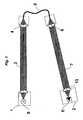
- FIG. 2 is a schematic representation of a further embodiment shown the optoelectronic device according to the invention, in which with two devices for beam deflection three partial beams between the light emitting unit 1 and the light receiving unit 2 are generated.
- the three Partial beams take any position in the room. Basically it is too possible to add further beam deflections to the beam in to decompose further partial beams. It is therefore easy to see that on this Paths with only one active light emitting and receiving unit also quite right complex beam paths are possible.
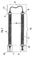
- FIG. 3 shows a beam guide in which the two partial beams 3 and 7 run in the parallel direction offset by a distance A.
- Such arrangements for securing access in which the two partial beams are arranged at different heights from the floor, are often prescribed in order to rule out the risk of the protective device being exceeded / undershot.
- the active light emitting unit 1 and the light receiving unit 2 can be arranged in a common housing 10, while on the opposite side of the monitoring section 12 the coupling and decoupling optics 4 and 6 and the optical waveguide 5 are likewise in a common Housing 11 are integrated.
- light does not only refer to the human eye accessible wavelength range to understand, but also the adjacent Spectral ranges from the ultraviolet and infrared range. Beyond that All types of light from constant light and alternating light are possible in the invention.
Landscapes
- Engineering & Computer Science (AREA)
- General Engineering & Computer Science (AREA)
- Physics & Mathematics (AREA)
- General Physics & Mathematics (AREA)
- Mechanical Engineering (AREA)
- Life Sciences & Earth Sciences (AREA)
- General Life Sciences & Earth Sciences (AREA)
- Geophysics (AREA)
- Optical Couplings Of Light Guides (AREA)
Applications Claiming Priority (2)
| Application Number | Priority Date | Filing Date | Title |
|---|---|---|---|
| DE10151327 | 2001-10-17 | ||
| DE10151327A DE10151327A1 (de) | 2001-10-17 | 2001-10-17 | Lichtgitter mit Lichtwellenleiter |
Publications (1)
| Publication Number | Publication Date |
|---|---|
| EP1312940A1 true EP1312940A1 (fr) | 2003-05-21 |
Family
ID=7702848
Family Applications (1)
| Application Number | Title | Priority Date | Filing Date |
|---|---|---|---|
| EP02022724A Withdrawn EP1312940A1 (fr) | 2001-10-17 | 2002-10-11 | Barrière optique avec guide d'ondes optiques |
Country Status (2)
| Country | Link |
|---|---|
| EP (1) | EP1312940A1 (fr) |
| DE (1) | DE10151327A1 (fr) |
Cited By (1)
| Publication number | Priority date | Publication date | Assignee | Title |
|---|---|---|---|---|
| WO2012031583A3 (fr) * | 2010-09-08 | 2012-10-11 | Pantron Instruments Gmbh | Barrière lumineuse |
Families Citing this family (3)
| Publication number | Priority date | Publication date | Assignee | Title |
|---|---|---|---|---|
| DE102004025751A1 (de) * | 2004-05-26 | 2005-12-22 | Sick Ag | Justiervorrichtung insbesondere für Lichtschranken oder Lichtgitter und Verfahren zur Justage |
| DE102011109669B4 (de) * | 2011-08-08 | 2015-05-07 | Von Ardenne Gmbh | Positionsdetektor für Glasscheiben |
| CN105182437A (zh) * | 2015-09-29 | 2015-12-23 | 国家电网公司 | 一种换流变油枕胶囊破裂在线监测装置及监测方法 |
Citations (4)
| Publication number | Priority date | Publication date | Assignee | Title |
|---|---|---|---|---|
| US4272189A (en) * | 1979-08-16 | 1981-06-09 | The United States Of America As Represented By The Secretary Of The Navy | Electro-optical projectile analyzer |
| US4539474A (en) * | 1982-06-21 | 1985-09-03 | Hondadenshigiken Co., Ltd. | Optical switch for an automatic door |
| JPS6179183A (ja) * | 1984-09-27 | 1986-04-22 | Fujitsu Ten Ltd | 光学式物体検出装置 |
| DE3532197A1 (de) * | 1985-09-10 | 1987-03-12 | Leuze Electronic Gmbh & Co | Lichtvorhang |
Family Cites Families (7)
| Publication number | Priority date | Publication date | Assignee | Title |
|---|---|---|---|---|
| US3623057A (en) * | 1969-05-14 | 1971-11-23 | Phinizy R B | Laser perimeter intrusion detection system |
| DD98083A1 (fr) * | 1972-06-27 | 1973-06-12 | ||
| DE2255788A1 (de) * | 1972-11-15 | 1974-05-16 | Peter Hans | Schutz von objekten (anlagen und gelaende) gegen unbefugtes eindringen mittels laser-verfahren |
| DE2805423B2 (de) * | 1978-02-09 | 1980-05-08 | 6000 Frankfurt | Lichtschrankenanordnung |
| US5075543A (en) * | 1990-05-29 | 1991-12-24 | Xerox Corporation | Light weight paper sensor using fibers |
| DE9321193U1 (de) * | 1993-10-29 | 1996-08-01 | Schlachter, Klemens, 89340 Leipheim | Anordnung zur Notabschaltung eines motorischen Antriebes zum Schließen von Dreh- und/oder Kippfenstern |
| DE19622495C2 (de) * | 1996-06-05 | 2003-12-18 | Ifm Electronic Gmbh | Fadenerkennungsgerät |
-
2001
- 2001-10-17 DE DE10151327A patent/DE10151327A1/de not_active Withdrawn
-
2002
- 2002-10-11 EP EP02022724A patent/EP1312940A1/fr not_active Withdrawn
Patent Citations (4)
| Publication number | Priority date | Publication date | Assignee | Title |
|---|---|---|---|---|
| US4272189A (en) * | 1979-08-16 | 1981-06-09 | The United States Of America As Represented By The Secretary Of The Navy | Electro-optical projectile analyzer |
| US4539474A (en) * | 1982-06-21 | 1985-09-03 | Hondadenshigiken Co., Ltd. | Optical switch for an automatic door |
| JPS6179183A (ja) * | 1984-09-27 | 1986-04-22 | Fujitsu Ten Ltd | 光学式物体検出装置 |
| DE3532197A1 (de) * | 1985-09-10 | 1987-03-12 | Leuze Electronic Gmbh & Co | Lichtvorhang |
Non-Patent Citations (1)
| Title |
|---|
| PATENT ABSTRACTS OF JAPAN vol. 010, no. 250 (P - 491) 28 August 1986 (1986-08-28) * |
Cited By (1)
| Publication number | Priority date | Publication date | Assignee | Title |
|---|---|---|---|---|
| WO2012031583A3 (fr) * | 2010-09-08 | 2012-10-11 | Pantron Instruments Gmbh | Barrière lumineuse |
Also Published As
| Publication number | Publication date |
|---|---|
| DE10151327A1 (de) | 2003-04-30 |
Similar Documents
| Publication | Publication Date | Title |
|---|---|---|
| DE2614051C2 (de) | Faseroptischer T-Koppler | |
| DE60314028T2 (de) | Optische Drehverbindung | |
| EP1947481B1 (fr) | Capteur optoélectronique et procédé de saisie d'objets dans une zone de surveillance | |
| EP0565090A1 (fr) | Procédé et dispositif pour mesurer les dimensions d'un objet | |
| DE2834821A1 (de) | Einrichtung zum ueberpruefen der betriebseigenschaften von laser-entfernungsmessgeraeten | |
| DE3338928C2 (de) | Tag- und Nachtsichtgerät | |
| EP1296161A2 (fr) | Barrière optique à séparateur de faisceaux | |
| DE19910321A1 (de) | Optikblock für Lichtschranken mit mindestens einem optischen Sende- oder Empfangselement | |
| DE102004017493B4 (de) | Optisches Kommunikationssystem und Freiraumoptikkommunikationsgerät | |
| DE202005010358U1 (de) | Optoelektronisches Lichtgitter | |
| CH628994A5 (en) | Electrooptical back reflection-type locating device | |
| EP1780559B1 (fr) | Capteur optique | |
| DE202007007290U1 (de) | Optoelektronische Sensoranordnung | |
| EP1312940A1 (fr) | Barrière optique avec guide d'ondes optiques | |
| DE2931818C2 (de) | Vorrichtung zur Erfassung der Einfallsrichtung elektromagnetischer, insbesondere optischer Strahlung | |
| DE202005017006U1 (de) | Lichtschranke mit Lichtschrankeneinheiten | |
| DE3411121A1 (de) | Vorrichtung zur uebertragung von lichtsignalen zwischen zwei bauteilen | |
| DE102012109311B4 (de) | Vorrichtung zum sicheren Überwachen einer Schließposition zweier relativ zueinander beweglicher Teile | |
| EP3495845A1 (fr) | Capteur optoélectronique et procédé de détection d'une zone de surveillance | |
| DE102018216201A1 (de) | Optische Anordnung und LIDAR-Vorrichtung mit einer derartigen Anordnung | |
| EP3208636B1 (fr) | Capteur optoélectronique et procédé destiné à la saisie d'objets | |
| DE19622495C2 (de) | Fadenerkennungsgerät | |
| EP1510750B1 (fr) | Dispositif optique de détection de position | |
| DE19537051C1 (de) | Optoelektronische Sensoranordnung | |
| DE10320991B4 (de) | Optische Positionsmesseinrichtung |
Legal Events
| Date | Code | Title | Description |
|---|---|---|---|
| PUAI | Public reference made under article 153(3) epc to a published international application that has entered the european phase |
Free format text: ORIGINAL CODE: 0009012 |
|
| AK | Designated contracting states |
Designated state(s): AT BE BG CH CY CZ DE DK EE ES FI FR GB GR IE IT LI LU MC NL PT SE SK TR |
|
| AX | Request for extension of the european patent |
Extension state: AL LT LV MK RO SI |
|
| 17P | Request for examination filed |
Effective date: 20030718 |
|
| AKX | Designation fees paid |
Designated state(s): AT BE BG CH CY CZ DE DK EE ES FI FR GB GR IE IT LI LU MC NL PT SE SK TR |
|
| 17Q | First examination report despatched |
Effective date: 20040719 |
|
| STAA | Information on the status of an ep patent application or granted ep patent |
Free format text: STATUS: THE APPLICATION IS DEEMED TO BE WITHDRAWN |
|
| 18D | Application deemed to be withdrawn |
Effective date: 20060321 |