EP1312933A2 - Verfahren und System zur Uberwachung des Batterieausgleichs - Google Patents
Verfahren und System zur Uberwachung des Batterieausgleichs Download PDFInfo
- Publication number
- EP1312933A2 EP1312933A2 EP02256922A EP02256922A EP1312933A2 EP 1312933 A2 EP1312933 A2 EP 1312933A2 EP 02256922 A EP02256922 A EP 02256922A EP 02256922 A EP02256922 A EP 02256922A EP 1312933 A2 EP1312933 A2 EP 1312933A2
- Authority
- EP
- European Patent Office
- Prior art keywords
- voltage
- batteries
- target
- battery
- node
- Prior art date
- Legal status (The legal status is an assumption and is not a legal conclusion. Google has not performed a legal analysis and makes no representation as to the accuracy of the status listed.)
- Granted
Links
Images



Classifications
-
- H—ELECTRICITY
- H02—GENERATION; CONVERSION OR DISTRIBUTION OF ELECTRIC POWER
- H02J—ELECTRIC POWER NETWORKS; CIRCUIT ARRANGEMENTS OR SYSTEMS FOR SUPPLYING OR DISTRIBUTING ELECTRIC POWER; SYSTEMS FOR STORING ELECTRIC ENERGY
- H02J7/00—Circuit arrangements for charging or discharging batteries or for supplying loads from batteries
- H02J7/50—Circuit arrangements for charging or discharging batteries or for supplying loads from batteries acting upon multiple batteries simultaneously or sequentially
- H02J7/52—Circuit arrangements for charging or discharging batteries or for supplying loads from batteries acting upon multiple batteries simultaneously or sequentially for charge balancing, e.g. equalisation of charge between batteries
-
- H—ELECTRICITY
- H02—GENERATION; CONVERSION OR DISTRIBUTION OF ELECTRIC POWER
- H02J—ELECTRIC POWER NETWORKS; CIRCUIT ARRANGEMENTS OR SYSTEMS FOR SUPPLYING OR DISTRIBUTING ELECTRIC POWER; SYSTEMS FOR STORING ELECTRIC ENERGY
- H02J7/00—Circuit arrangements for charging or discharging batteries or for supplying loads from batteries
- H02J7/60—Circuit arrangements for charging or discharging batteries or for supplying loads from batteries including safety or protection arrangements
- H02J7/61—Circuit arrangements for charging or discharging batteries or for supplying loads from batteries including safety or protection arrangements against overcharge
-
- Y—GENERAL TAGGING OF NEW TECHNOLOGICAL DEVELOPMENTS; GENERAL TAGGING OF CROSS-SECTIONAL TECHNOLOGIES SPANNING OVER SEVERAL SECTIONS OF THE IPC; TECHNICAL SUBJECTS COVERED BY FORMER USPC CROSS-REFERENCE ART COLLECTIONS [XRACs] AND DIGESTS
- Y02—TECHNOLOGIES OR APPLICATIONS FOR MITIGATION OR ADAPTATION AGAINST CLIMATE CHANGE
- Y02T—CLIMATE CHANGE MITIGATION TECHNOLOGIES RELATED TO TRANSPORTATION
- Y02T10/00—Road transport of goods or passengers
- Y02T10/60—Other road transportation technologies with climate change mitigation effect
- Y02T10/70—Energy storage systems for electromobility, e.g. batteries
Definitions
- This invention relates to vehicle electrical systems that use more than one operating voltage.
- a vehicle e.g. an automotive system
- one of them involves the use of an alternator that powers, among other loads, a battery equalizer.
- the purpose of the battery equalizer is to balance the charge among series-connected batteries to ensure equal charging. This is especially important if one of the series-connections between the batteries represents a point where electrical loads are connected.
- the charge voltage at the highest series-connected battery potential is typically controlled by a voltage regulator that controls the output voltage of the alternator.
- Series-connected batteries all need similar charge characteristics if they are to be equally recharged in series. If an intermediate operating voltage is derived from a series connection between batteries, the electrical loads at that point will unbalance the electrical charge that is attempting to recharge the battery at the lower potential. Also, if batteries with different charge characteristics are series connected, there will be unbalanced charging. In any type of unbalanced series charging, the battery at the higher potential will tend to overcharge, and the battery at the lower potential will tend to undercharge. In time, the overcharging battery will be destroyed, and the entire electrical system will malfunction.
- An equalizer prevents battery charge imbalance because it has the capability of shunting current from the higher potential to the lower potential in order to maintain an equal potential across each of the batteries in series.
- an equalizer is a current rated device and typically has a protective circuit that prevents operating beyond its rated limit. If excessive electrical loads or a deeply discharged battery causes the operating current to exceed the equalizer rating, the equalizer may malfunction, shut down, or continue operating at its self imposed protective limit. In each of these cases the equalizer will cease to perform its equalizing function, and the higher potential battery will overcharge while the lower potential battery will undercharge.
- the preferred embodiment described below seeks to overcome the limitation of the equalizer described above by introducing a voltage regulator that monitors the voltage at the series connection of series-connected batteries.
- the regulator is programmed to identify when an overload or malfunction occurs across any of the individual battery voltages. If this happens, the voltage regulator can adjust its regulated setting to a voltage that prevents the malfunctioning battery from overcharging. This, of necessity, may cause other batteries in the series to be undercharged, but at least it will prevent permanent overcharge damage and unsafe operation.
- a fault signal to alert the operator of this condition is provided. If the malfunction or overloaded condition cannot be corrected within the programmed range of output voltage adjustment, the regulator will turn off the alternator. If the overloaded condition corrects itself, the voltage regulator may return to normal operation at its original regulated setting.
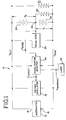
- FIG. 1 shows a block diagram of a vehicle (e.g. automotive) electrical system 10 that incorporates a preferred embodiment of this invention.
- the system 10 includes an alternator 12 having output terminals 14, 16.
- the alternator 12 may for example be driven by an internal combustion engine (not shown), and it generates output voltages V OUT and V GND as shown.
- a voltage regulator 18 is coupled with the alternator 12. The voltage regulator 18 maintains the output voltage V OUT at a desired output voltage.
- the alternator 12 in this example includes an AC generator, a power control element such as a field coil or a rectifier controller, and an AC to DC controlled or uncontrolled converter.
- a wide variety of devices can be used for the alternator 12, and this invention is not limited to any particular type of alternator.
- the voltage regulator 18 can be implemented in many ways as either an electronic or an electromechanical circuit having the basic function of operating the power control element of the alternator to maintain a specific DC output voltage. The voltage regulator 18 may perform additional functions as well.
- the output voltages V OUT and V GND are applied across a string of series-connected batteries, including first and second batteries 22, 24 in this example.
- the first and second batteries 22, 24 are interconnected at a node 26.
- a wide variety of energy or power storage elements may be used for the batteries 22, 24, including electrochemical devices such as electrolyte cells and electrostatic device such as capacitors,
- An equalizer 20 is coupled to the node 26 and to the output voltages V OUT and V GND .
- the equalizer 20 can be implemented in many ways, including electronic circuits and electromechanical circuits that operate to maintain each of the batteries 22, 24 at an equal proportion of the total voltage drop across the string of series-connected batteries.
- the example of FIG. 1 includes only two batteries 22, 24 in the string of batteries, but alternative embodiments may include three, four or more batteries connected in series between the output voltages V OUT and V GND .
- the battery 22 is connected to an electrical system having a lower nominal voltage.
- the battery 22 may be a lead-acid battery, and the lower voltage system may be a 14V system having a nominal voltage in the range of 10-16V. Though shown as a single battery 22, the 14V system may use two or more 14V batteries connected in parallel with one another.
- the 14V system powers a 14V load, indicated schematically at 28.
- the batteries 22, 24 are connected to a higher voltage system.
- the higher voltage system is a 28V system having a nominal voltage in the range of 20-32V.
- the 28V system may use one or more parallel combinations of two 14V batteries in series, and it powers a 28V load, indicated schematically at 30.
- the higher voltage system may be a 42V system having a nominal voltage in the range of 30-48V, and may use one or more parallel combinations of three 14V batteries in series.
- the lower voltage system may be at any of various fractions of the higher voltage system, such as 1 ⁇ 2, 1 ⁇ 4 or other fractions.
- the system of FIG. 1 is a dual voltage-system in the sense that electrical power is applied to electrical loads at two separate operating voltages.
- This invention is also useful in multiple-voltage systems having more than two independent operating voltages for electrical loads.
- 42, 28, and 14V electrical systems may all be connected to a single string of three series-connected 14V batteries connected to a 42V alternator.
- the equalizer 20 prevents uneven charging of the batteries 22, 24, as for example uneven charging associated with current drained by the load 28. Such a current drain would, without operation of the equalizer 20, result in an under-charged condition for the battery 22 and therefore an overcharged condition for the battery 24.
- a multiple-voltage system would typically include an equalizer connected in some way to each battery of the series-connected battery string. The equalizer prevents the lower-voltage loads from resulting in uneven charging of the series-connected batteries.
- the elements 12-30 described above may be entirely conventional, and they may be implemented in many ways.
- the present invention is readily adapted to use with the widest variety of alternators, voltage regulators, equalizers, batteries, and loads.
- the system 10 also includes an equalization monitor 40 that is coupled to the output voltages V OUT and V GND as well as to the voltage V NODE of the node 26.
- the equalization monitor 40 generates a target voltage V TARGET that is applied to the voltage regulator 18 and that sets the target value for the output voltage V OUT .
- V TARGET may also be a logic signal, e.g., a voltage increment/voltage decrement logic state.
- the equalization monitor 40 also generates an output signal S WARNING that controls operation of a warning lamp 42.
- the equalization monitor 40 though shown as a separate block in FIG. 1, can in practice be integrated with the voltage regulator 18.
- FIG. 2 provides a more detailed block diagram of the equalization monitor 40
- FIGS. 3, 4 and 5 illustrate operation of the equalization monitor 40.
- the monitor 40 includes first and second adders 44, 46 that are connected to first and second comparators 48 and 50.
- the first adder 44 generates an output signal V 1 that is equal to the difference between V NODE and V GND .
- the output signal V 1 is equal to the voltage drop across the battery 22.
- the comparator 48 compares the signal V 1 with a threshold T 1 and generates an output signal commanding operation of a decrementor 54 when the voltage V 1 exceeds the threshold T 1 .
- the adder 46 generates an output signal V 2 equal to the difference between V OUT and V NODE .
- the output signal V 2 is indicative of the voltage drop across the battery 24.
- the signal V 2 is applied to the comparator 50, which compares the signal V 2 with a threshold T 2 and generates an output signal commanding operation of the decrementor 54 when the voltage V 2 exceeds the threshold T 2 .
- the output signals of the comparators 48, 50 are applied to an OR gate 52 which controls operation of the decrementor 54.
- the decrementor 54 reduces or decrements the target value V TARGET in response to commands from either of the comparators 48, 50.
- the monitor 40 also includes a warning signal generator 56 that generates the warning signal S WARMING as described below in conjunction with FIG. 4.
- FIG. 2 schematically illustrates components of the equalization monitor 40. It should be understood that the equalization monitor 40 can be implemented in many ways, including analog electronics, digital electronics, and programmed processors. FIGS. 3 and 4 illustrate operation of the monitor 40 of FIG. 2.
- FIG. 3 flow-charts the operation of the elements 44-54 of FIG. 2.
- the monitor measures V OUT and V NODE .
- V 1 is set equal to V NODE minus V GND and V 2 is set equal to V OUT minus V NODE .
- V 1 represents the voltage drop across the battery 22 and V 2 represents the voltage drop across the battery 24.
- V 1 is compared with the threshold T 1 .
- the target value V TARGET is reduced in block 76 and control is returned to block 74. This procedure continues until V 1 is no longer greater than T 1 .
- Control then transfers to block 78, where V 2 is compared with the threshold T 2 .
- the target value V TARGET is reduced in block 80 and control is returned to block 78. This loop is repeated until V 2 is no longer greater than T 2 . At this point execution is delayed in block 82, and control is then returned to block 70.
- T 1 is set equal to the nominal voltage for the battery 22 plus 0.5V
- T 2 is set equal to the nominal voltage of the battery 24 plus 0.5V.
- V 1 and V 2 must exceed the respective thresholds T 1 , T 2 for a extended time period (e.g. 3 seconds) before control is transferred to block 76 or 80.
- the method diagrammed in FIG. 2 protects the batteries from being overcharged in the event of a failure of the equalizer or in the event that an excessive load reduces the voltage at node 26 excessively.
- FIG. 4 provides a flow chart of a method implemented by the warning signal generator 56 of FIG. 2.
- the warning signal generator 56 first measures (V 1 + V 2 ) and V 1 .
- V 1 + V 2 is equal to the difference between V OUT and V GND
- V 1 is equal to the difference between V NODE and V GND .
- V 1 is compared with a value equal to (V 1 + V 2 )/2 minus a threshold. For example, the threshold may be 0.2V. If V 1 is less than this value, control is transferred to block 72 where the warning signal S WARNING is set to state A.
- V 1 is compared with a second value equal to (V 1 + V 2) /2 plus a threshold. Once again, the threshold may be equal to 0.2V. In the event that V 1 exceeds this value, control is transferred to block 98, where the warning signal S WARNING is set to state A. Control is then transferred to block 100, which imposes a delay on execution, and control is then returned to block 93. In this example, the warning lamp 42 of FIG. 1 is illuminated when the warning signal S WARNING is set equal to state A.
- FIGS. 3 and 4 include delay blocks, which are typically appropriate for digital and in particular programmed microprocessor implementations. Analogous functions can be performed in an analog manner, in which case the delay blocks may not be required.
- the voltage regulator 18 is connected to the power control element of the alternator 12, which may for example be a field coil.
- the regulator 18 controls the amount of field current flowing in the field coil to maintain the alternator output voltage V OUT at a selected value, equal to V TARGET in this example.
- the current flowing to the field coil will be increased and decreased as necessary to maintain V OUT at the desired level as electrical loads are added or removed.
- the regulator 18 may also shut off field coil current when the alternator 12 is not rotating or when voltage regulation control has been lost due to failure of components in the field current switching circuit.
- the equalization monitor 40 generates a warning signal S WARNING that has two possible states.
- the fault state is a 0V signal indicative of a fault in the electrical system or an alternator that is not producing power.
- the normal state is a positive DC voltage signal when the alternator 12 is producing power and no detectable faults are present in the system.
- the logic of the two states may be switched or configured to sink current, but distinctly different states are used to represent the two cases.
- the equalization monitor 40 routinely checks the voltage at each terminal of the equalizer 20. If any of these voltages differs from the respective proportional value by less than a preset threshold (e.g. ⁇ 0.2V), the warning signal S WARMING is placed in the normal state.
- a preset threshold e.g. ⁇ 0.2V
- the warning signal S WARNING will be placed in the normal state when the voltage V node is equal to 14.2V ⁇ 0.2V.
- the threshold accommodates voltage offsets for normal equalizer operation that may include voltage drops along cables used in the electrical system.
- the equalization monitor 40 (in particular the warning signal generator 56) detects that a lower system voltage such as the voltage V NODE is operating outside of the threshold limits for a designated period of time, it determines that the equalizer 20 has either failed, or that the lower system voltage is overloaded. In this case the warning signal S WARNING is set to the fault state, causing the lamp 42 to be illuminated.
- the fault may also be signaled through other vehicle control circuits, such as a digital bus for example. In an analog implementation of this function, the lower system voltage or voltages may be monitored continuously, while in a digital implementation such monitoring may be performed on a periodic basis.
- a charge-ok light circuit is enabled in the normal state and the charge-ok light circuit is disabled in the fault state of the warning signal S WARNING .
- a no-charge light circuit may be enabled when the warning signal S WARNING is in the fault state, either continuously, or intermittently to indicate that the equalization monitor 40 is active.
- the equalization monitor 40 also provides automatic battery protection.
- An equalizer failure or an overload may cause one of the lower-voltage systems to operate outside of the programmed threshold, and below its respective proportion of the system voltage.
- one of the lower-voltage systems may operate outside its programmed threshold and above its respective proportion of the system voltage. Both situations cause uneven battery charging that may degrade the batteries and endanger the entire electrical system. Overcharging an automotive battery may dissipate the electrolyte to the point of damaging the battery beyond repair. Either type of failure places the warning signal S WARMING in the fault condition as described above.
- the equalization monitor 40 also responds to a problem of this type by altering the value of V TARGET . If either V 1 or V 2 is larger than the respective maximum permissible value, the equalization monitor 40 reduces V TARGET . This enables the alternator 12 to continue operating while also protecting the system batteries. For example, in a dual voltage 14V/28V system, if the 14V system drops to 10V, the equalization monitor 40 will reduce V TARGET from 28V to 24V, thereby preventing the upper battery 24 from charging at 18V (28V-10V). As described above, the equalization monitor 40 limits the maximum voltage across each battery to a respective defined limit, and prevents the voltage across each battery from exceeding the respective limit.
- the equalization monitor 40 will reduce V TARGET , thereby reducing V OUT to the point where the equalizer output voltage V NODE falls below the maximum programmed limit for the 14V system. For example, in a dual voltage 14V/28V system, if the 14V system rises to 16V, then a reduction in V TARGET to lower V OUT from 28V to 26V should return the 14V system to approximately 14V. The alternator will continue to produce power while the lower voltage system is regulated at 12V and the upper voltage system is regulated at 26V. As before, the warning signal S WARNING is placed in the fault state to indicate that the system is degraded even though the alternator continues to produce power.
- an overload or system malfunction causes voltage compensation to exceed a programmed differentral voltage, e.g. 4V, then the regulator will turn off field current. Such a condition may occur with a short in one of the electrical systems or with a short in the equalizer between 28V and 14V. This causes the alternator to cease producing power, and the no-charge light circuit is activated.
- a programmed differentral voltage e.g. 4V
- FIG. 5 provides a schematic representation of the operation of the system of FIGS. 1-5, with reference to the voltage V 1 across the lower battery 22.
- the dotted line is used to indicate the nominal voltage of the 14V system.
- the warning signal S WARNING is in the normal state.
- V1 exceeds the upper threshold No. 1 or falls below the lower threshold No. 1
- the warning signal S WARNING is changed to the fault state to indicate that the system is not operating normally.
- V 1 exceeds the upper threshold No.
- the monitor 40 begins to reduce the value of V TARGET , thereby reducing V OUT and protecting the lower battery 22.
- a similar set of thresholds is used to protect the battery 24.
- the monitor 40 may be used in electrical systems that do not include an equalizer, e.g. to monitor against uneven charging caused by connection of a load to the node 26.
- the monitor 40 can also be used in electrical systems that do not include one or both of the loads 28, 30.
- alternator is intended broadly to uncover a wide range of devices for generating DC power, including alternators, generators and other devices.
- the term “comparator” is also intended broadly to encompass analog, digital and programmed processor implementations.
- set is used to mean one or more.
- a set of batteries can include one, two, or more batteries.
Landscapes
- Engineering & Computer Science (AREA)
- Power Engineering (AREA)
- Charge And Discharge Circuits For Batteries Or The Like (AREA)
- Secondary Cells (AREA)
- Control Of Charge By Means Of Generators (AREA)
Applications Claiming Priority (2)
| Application Number | Priority Date | Filing Date | Title |
|---|---|---|---|
| US09/989,664 US6489753B1 (en) | 2001-11-19 | 2001-11-19 | System and method for monitoring battery equalization |
| US989664 | 2001-11-19 |
Publications (3)
| Publication Number | Publication Date |
|---|---|
| EP1312933A2 true EP1312933A2 (de) | 2003-05-21 |
| EP1312933A3 EP1312933A3 (de) | 2005-04-27 |
| EP1312933B1 EP1312933B1 (de) | 2007-08-01 |
Family
ID=25535335
Family Applications (1)
| Application Number | Title | Priority Date | Filing Date |
|---|---|---|---|
| EP02256922A Expired - Lifetime EP1312933B1 (de) | 2001-11-19 | 2002-10-07 | Verfahren und System zur Uberwachung des Batterieausgleichs |
Country Status (7)
| Country | Link |
|---|---|
| US (1) | US6489753B1 (de) |
| EP (1) | EP1312933B1 (de) |
| AT (1) | ATE368867T1 (de) |
| AU (1) | AU2002301493B2 (de) |
| CA (1) | CA2412154C (de) |
| DE (1) | DE60221482T2 (de) |
| ES (1) | ES2290250T3 (de) |
Families Citing this family (16)
| Publication number | Priority date | Publication date | Assignee | Title |
|---|---|---|---|---|
| US6844704B2 (en) * | 2001-10-04 | 2005-01-18 | Ise Corp. | Voltage threshold device and energy storage cell failure detection system for power supply |
| US6909201B2 (en) * | 2003-01-06 | 2005-06-21 | General Motors Corporation | Dual voltage architecture for automotive electrical systems |
| US20060087287A1 (en) * | 2004-10-27 | 2006-04-27 | Maxwell Technologies, Inc. | Voltage monitoring for connected electrical energy storage cells |
| US7642748B2 (en) * | 2005-10-19 | 2010-01-05 | General Electric Company | Battery charging system and method of operating same |
| US7994657B2 (en) * | 2006-12-22 | 2011-08-09 | Solarbridge Technologies, Inc. | Modular system for unattended energy generation and storage |
| EP2307218B1 (de) | 2008-06-27 | 2015-09-30 | Proterra Inc. | Fahrzeugbatteriesysteme und verfahren |
| DE102009027833A1 (de) * | 2009-07-20 | 2011-01-27 | SB LiMotive Company Ltd., Suwon | Serienschaltung von Schaltreglern zur Energieübertragung in Batteriesystemen |
| CN102375098A (zh) * | 2010-08-10 | 2012-03-14 | 光宝动力储能科技股份有限公司 | 电池等化器的检测模块及检测方法 |
| US8471529B2 (en) * | 2010-10-14 | 2013-06-25 | GM Global Technology Operations LLC | Battery fault tolerant architecture for cell failure modes parallel bypass circuit |
| US8723482B2 (en) * | 2010-11-04 | 2014-05-13 | Elite Power Solutions Llc | Battery unit balancing system |
| JP2013210206A (ja) * | 2012-03-30 | 2013-10-10 | Toyota Industries Corp | 車載バッテリの充電状態推定装置 |
| DE102014222337B3 (de) * | 2014-10-31 | 2016-01-21 | Continental Teves Ag & Co. Ohg | Verfahren und Vorrichtung zur Steuerung eines fremderregten elektrischen Generators in einem Bordnetz eines Kraftfahrzeuges |
| DE112017000318B4 (de) * | 2016-06-03 | 2024-01-18 | Fuji Electric Co., Ltd. | Halbleitervorrichtung |
| US20180138555A1 (en) * | 2016-11-17 | 2018-05-17 | Gulfstream Aerospace Corporation | Self-switching dual voltage battery |
| PL3360719T3 (pl) * | 2017-02-09 | 2021-04-19 | Samsung Sdi Co., Ltd | Podwójny układ zasilania |
| EP3743307B1 (de) * | 2018-01-25 | 2023-11-22 | Volvo Construction Equipment AB | Entzerrerüberlastungsmanagement |
Family Cites Families (13)
| Publication number | Priority date | Publication date | Assignee | Title |
|---|---|---|---|---|
| US3667025A (en) * | 1971-06-21 | 1972-05-30 | Gen Motors Corp | Dual voltage system |
| US4238721A (en) * | 1979-02-06 | 1980-12-09 | The United States Of America As Represented By The United States Department Of Energy | System and method for charging electrochemical cells in series |
| US4479083B1 (en) | 1982-09-30 | 1998-09-01 | Vanner Weldon Inc | DC power system having battery voltage equalizer circuit |
| US4967136A (en) | 1989-09-25 | 1990-10-30 | Prestolite Electric Incorporated | Battery equalization circuit for a dual voltage charging system |
| US5479083A (en) | 1993-06-21 | 1995-12-26 | Ast Research, Inc. | Non-dissipative battery charger equalizer |
| US5528122A (en) | 1994-11-29 | 1996-06-18 | Ventron Corporation | Battery voltage equalizer circuit |
| US5666041A (en) | 1996-08-27 | 1997-09-09 | The University Of Toledo | Battery equalization circuit with ramp converter |
| EP1205022A4 (de) | 1999-06-11 | 2004-07-14 | Pri Automation Inc | Ultrakondensatorstromversorgung für einem elektrischen fahrzeung. |
| US6194877B1 (en) | 1999-08-02 | 2001-02-27 | Visteon Global Technologies, Inc. | Fault detection in a motor vehicle charging system |
| US6150795A (en) | 1999-11-05 | 2000-11-21 | Power Designers, Llc | Modular battery charge equalizers and method of control |
| US6310556B1 (en) * | 2000-02-14 | 2001-10-30 | Sonic Innovations, Inc. | Apparatus and method for detecting a low-battery power condition and generating a user perceptible warning |
| FR2805934B1 (fr) * | 2000-03-01 | 2002-07-26 | Agence Spatiale Europeenne | Procede et dispositif d'equilibrage des charges d'une pluralite de cellules de batteries montees en serie |
| US6417648B2 (en) * | 2000-06-28 | 2002-07-09 | Nissan Motor Co., Ltd. | Method of and apparatus for implementing capacity adjustment in battery pack |
-
2001
- 2001-11-19 US US09/989,664 patent/US6489753B1/en not_active Expired - Lifetime
-
2002
- 2002-10-07 EP EP02256922A patent/EP1312933B1/de not_active Expired - Lifetime
- 2002-10-07 AT AT02256922T patent/ATE368867T1/de active
- 2002-10-07 ES ES02256922T patent/ES2290250T3/es not_active Expired - Lifetime
- 2002-10-07 DE DE60221482T patent/DE60221482T2/de not_active Expired - Lifetime
- 2002-10-16 AU AU2002301493A patent/AU2002301493B2/en not_active Ceased
- 2002-11-19 CA CA002412154A patent/CA2412154C/en not_active Expired - Fee Related
Also Published As
| Publication number | Publication date |
|---|---|
| CA2412154C (en) | 2005-04-19 |
| AU2002301493B2 (en) | 2005-04-28 |
| ES2290250T3 (es) | 2008-02-16 |
| US6489753B1 (en) | 2002-12-03 |
| EP1312933A3 (de) | 2005-04-27 |
| ATE368867T1 (de) | 2007-08-15 |
| CA2412154A1 (en) | 2003-05-19 |
| DE60221482D1 (de) | 2007-09-13 |
| DE60221482T2 (de) | 2008-01-24 |
| EP1312933B1 (de) | 2007-08-01 |
Similar Documents
| Publication | Publication Date | Title |
|---|---|---|
| US6489753B1 (en) | System and method for monitoring battery equalization | |
| US20080084182A1 (en) | Lithium battery system | |
| US8581557B2 (en) | Direct-current power source apparatus | |
| JP3638658B2 (ja) | 電池再充電装置および電池再充電方法 | |
| US8749193B1 (en) | Battery protection circuit for multiple battery power supply and charging system | |
| US6377024B1 (en) | Method and system for charge equalization of lithium-ion batteries | |
| US8917061B2 (en) | System and method for battery cell balancing | |
| US20060061922A1 (en) | Hybrid power supply system having energy storage device protection circuit | |
| US6998818B2 (en) | Charging circuit with two levels of safety | |
| JP5301036B2 (ja) | 車両用の搭載電気系統および搭載電気系統の制御装置 | |
| JP2002525019A (ja) | バッテリー充電装置 | |
| KR101927124B1 (ko) | 배터리 고장 방지 장치 | |
| WO2019021007A1 (en) | Battery management | |
| CN110838746B (zh) | 一种电池并联电路和电池并联器 | |
| JP2005269828A (ja) | ハイブリッドシステム | |
| CN104969439B (zh) | 用于运行机动车的车载电网的供电单元的方法 | |
| KR101977165B1 (ko) | 비상 전원용 ess 제어 시스템, 방법, 및 상기 방법을 실행시키기 위한 컴퓨터 판독 가능한 프로그램을 기록한 기록 매체 | |
| KR102254088B1 (ko) | 잠수함 및 잠수함의 구동 시스템을 동작시키기 위한 방법 | |
| KR100520568B1 (ko) | 환경 자동차의 보조 배터리 과충전 방지 제어방법 | |
| JP7152892B2 (ja) | 直流給電システム | |
| JP7755148B2 (ja) | 電力貯蔵システム | |
| JP2004139810A (ja) | 燃料電池の給電システム | |
| US20250373011A1 (en) | Robust electrical power supply assembly with adaptive power control | |
| RU2624447C1 (ru) | Способ управления автономной системой электропитания космического аппарата | |
| JP3438751B2 (ja) | 充電可能な電池の過放電防止装置 |
Legal Events
| Date | Code | Title | Description |
|---|---|---|---|
| PUAI | Public reference made under article 153(3) epc to a published international application that has entered the european phase |
Free format text: ORIGINAL CODE: 0009012 |
|
| AK | Designated contracting states |
Designated state(s): AT BE BG CH CY CZ DE DK EE ES FI FR GB GR IE IT LI LU MC NL PT SE SK TR |
|
| AX | Request for extension of the european patent |
Extension state: AL LT LV MK RO SI |
|
| PUAL | Search report despatched |
Free format text: ORIGINAL CODE: 0009013 |
|
| AK | Designated contracting states |
Kind code of ref document: A3 Designated state(s): AT BE BG CH CY CZ DE DK EE ES FI FR GB GR IE IT LI LU MC NL PT SE SK TR |
|
| AX | Request for extension of the european patent |
Extension state: AL LT LV MK RO SI |
|
| 17P | Request for examination filed |
Effective date: 20050725 |
|
| AKX | Designation fees paid |
Designated state(s): AT BE BG CH CY CZ DE DK EE ES FI FR GB GR IE IT LI LU MC NL PT SE SK TR |
|
| GRAP | Despatch of communication of intention to grant a patent |
Free format text: ORIGINAL CODE: EPIDOSNIGR1 |
|
| GRAS | Grant fee paid |
Free format text: ORIGINAL CODE: EPIDOSNIGR3 |
|
| GRAA | (expected) grant |
Free format text: ORIGINAL CODE: 0009210 |
|
| AK | Designated contracting states |
Kind code of ref document: B1 Designated state(s): AT BE BG CH CY CZ DE DK EE ES FI FR GB GR IE IT LI LU MC NL PT SE SK TR |
|
| REG | Reference to a national code |
Ref country code: GB Ref legal event code: FG4D |
|
| REG | Reference to a national code |
Ref country code: CH Ref legal event code: EP Ref country code: CH Ref legal event code: NV Representative=s name: FELBER & PARTNER AG PATENTANWAELTE |
|
| REG | Reference to a national code |
Ref country code: IE Ref legal event code: FG4D |
|
| REF | Corresponds to: |
Ref document number: 60221482 Country of ref document: DE Date of ref document: 20070913 Kind code of ref document: P |
|
| REG | Reference to a national code |
Ref country code: SE Ref legal event code: TRGR |
|
| REG | Reference to a national code |
Ref country code: GR Ref legal event code: EP Ref document number: 20070403286 Country of ref document: GR |
|
| ET | Fr: translation filed | ||
| PG25 | Lapsed in a contracting state [announced via postgrant information from national office to epo] |
Ref country code: FI Free format text: LAPSE BECAUSE OF FAILURE TO SUBMIT A TRANSLATION OF THE DESCRIPTION OR TO PAY THE FEE WITHIN THE PRESCRIBED TIME-LIMIT Effective date: 20070801 Ref country code: BG Free format text: LAPSE BECAUSE OF FAILURE TO SUBMIT A TRANSLATION OF THE DESCRIPTION OR TO PAY THE FEE WITHIN THE PRESCRIBED TIME-LIMIT Effective date: 20071101 |
|
| REG | Reference to a national code |
Ref country code: ES Ref legal event code: FG2A Ref document number: 2290250 Country of ref document: ES Kind code of ref document: T3 |
|
| PG25 | Lapsed in a contracting state [announced via postgrant information from national office to epo] |
Ref country code: DK Free format text: LAPSE BECAUSE OF FAILURE TO SUBMIT A TRANSLATION OF THE DESCRIPTION OR TO PAY THE FEE WITHIN THE PRESCRIBED TIME-LIMIT Effective date: 20070801 |
|
| PG25 | Lapsed in a contracting state [announced via postgrant information from national office to epo] |
Ref country code: PT Free format text: LAPSE BECAUSE OF FAILURE TO SUBMIT A TRANSLATION OF THE DESCRIPTION OR TO PAY THE FEE WITHIN THE PRESCRIBED TIME-LIMIT Effective date: 20080102 Ref country code: CZ Free format text: LAPSE BECAUSE OF FAILURE TO SUBMIT A TRANSLATION OF THE DESCRIPTION OR TO PAY THE FEE WITHIN THE PRESCRIBED TIME-LIMIT Effective date: 20070801 Ref country code: SK Free format text: LAPSE BECAUSE OF FAILURE TO SUBMIT A TRANSLATION OF THE DESCRIPTION OR TO PAY THE FEE WITHIN THE PRESCRIBED TIME-LIMIT Effective date: 20070801 Ref country code: MC Free format text: LAPSE BECAUSE OF NON-PAYMENT OF DUE FEES Effective date: 20071031 |
|
| PLBE | No opposition filed within time limit |
Free format text: ORIGINAL CODE: 0009261 |
|
| STAA | Information on the status of an ep patent application or granted ep patent |
Free format text: STATUS: NO OPPOSITION FILED WITHIN TIME LIMIT |
|
| 26N | No opposition filed |
Effective date: 20080506 |
|
| PG25 | Lapsed in a contracting state [announced via postgrant information from national office to epo] |
Ref country code: IE Free format text: LAPSE BECAUSE OF NON-PAYMENT OF DUE FEES Effective date: 20071008 |
|
| PG25 | Lapsed in a contracting state [announced via postgrant information from national office to epo] |
Ref country code: EE Free format text: LAPSE BECAUSE OF FAILURE TO SUBMIT A TRANSLATION OF THE DESCRIPTION OR TO PAY THE FEE WITHIN THE PRESCRIBED TIME-LIMIT Effective date: 20070801 |
|
| PG25 | Lapsed in a contracting state [announced via postgrant information from national office to epo] |
Ref country code: CY Free format text: LAPSE BECAUSE OF FAILURE TO SUBMIT A TRANSLATION OF THE DESCRIPTION OR TO PAY THE FEE WITHIN THE PRESCRIBED TIME-LIMIT Effective date: 20070801 |
|
| PG25 | Lapsed in a contracting state [announced via postgrant information from national office to epo] |
Ref country code: LU Free format text: LAPSE BECAUSE OF NON-PAYMENT OF DUE FEES Effective date: 20071007 |
|
| PGFP | Annual fee paid to national office [announced via postgrant information from national office to epo] |
Ref country code: FR Payment date: 20141021 Year of fee payment: 13 Ref country code: TR Payment date: 20141001 Year of fee payment: 13 Ref country code: DE Payment date: 20141031 Year of fee payment: 13 Ref country code: GB Payment date: 20141024 Year of fee payment: 13 Ref country code: CH Payment date: 20141024 Year of fee payment: 13 Ref country code: ES Payment date: 20141024 Year of fee payment: 13 Ref country code: SE Payment date: 20141024 Year of fee payment: 13 Ref country code: GR Payment date: 20141024 Year of fee payment: 13 |
|
| PGFP | Annual fee paid to national office [announced via postgrant information from national office to epo] |
Ref country code: NL Payment date: 20141023 Year of fee payment: 13 Ref country code: AT Payment date: 20141022 Year of fee payment: 13 |
|
| PGFP | Annual fee paid to national office [announced via postgrant information from national office to epo] |
Ref country code: IT Payment date: 20141027 Year of fee payment: 13 |
|
| PGFP | Annual fee paid to national office [announced via postgrant information from national office to epo] |
Ref country code: BE Payment date: 20141020 Year of fee payment: 13 |
|
| REG | Reference to a national code |
Ref country code: DE Ref legal event code: R119 Ref document number: 60221482 Country of ref document: DE |
|
| REG | Reference to a national code |
Ref country code: SE Ref legal event code: EUG Ref country code: CH Ref legal event code: PL |
|
| REG | Reference to a national code |
Ref country code: AT Ref legal event code: MM01 Ref document number: 368867 Country of ref document: AT Kind code of ref document: T Effective date: 20151007 |
|
| GBPC | Gb: european patent ceased through non-payment of renewal fee |
Effective date: 20151007 |
|
| REG | Reference to a national code |
Ref country code: NL Ref legal event code: MM Effective date: 20151101 |
|
| REG | Reference to a national code |
Ref country code: GR Ref legal event code: ML Ref document number: 20070403286 Country of ref document: GR Effective date: 20160506 |
|
| PG25 | Lapsed in a contracting state [announced via postgrant information from national office to epo] |
Ref country code: GB Free format text: LAPSE BECAUSE OF NON-PAYMENT OF DUE FEES Effective date: 20151007 Ref country code: LI Free format text: LAPSE BECAUSE OF NON-PAYMENT OF DUE FEES Effective date: 20151031 Ref country code: GR Free format text: LAPSE BECAUSE OF NON-PAYMENT OF DUE FEES Effective date: 20160506 Ref country code: IT Free format text: LAPSE BECAUSE OF NON-PAYMENT OF DUE FEES Effective date: 20151007 Ref country code: CH Free format text: LAPSE BECAUSE OF NON-PAYMENT OF DUE FEES Effective date: 20151031 Ref country code: DE Free format text: LAPSE BECAUSE OF NON-PAYMENT OF DUE FEES Effective date: 20160503 |
|
| REG | Reference to a national code |
Ref country code: FR Ref legal event code: ST Effective date: 20160630 |
|
| PG25 | Lapsed in a contracting state [announced via postgrant information from national office to epo] |
Ref country code: SE Free format text: LAPSE BECAUSE OF NON-PAYMENT OF DUE FEES Effective date: 20151008 Ref country code: FR Free format text: LAPSE BECAUSE OF NON-PAYMENT OF DUE FEES Effective date: 20151102 Ref country code: NL Free format text: LAPSE BECAUSE OF NON-PAYMENT OF DUE FEES Effective date: 20151101 Ref country code: AT Free format text: LAPSE BECAUSE OF NON-PAYMENT OF DUE FEES Effective date: 20151007 |
|
| REG | Reference to a national code |
Ref country code: ES Ref legal event code: FD2A Effective date: 20161125 |
|
| PG25 | Lapsed in a contracting state [announced via postgrant information from national office to epo] |
Ref country code: ES Free format text: LAPSE BECAUSE OF NON-PAYMENT OF DUE FEES Effective date: 20151008 |
|
| PG25 | Lapsed in a contracting state [announced via postgrant information from national office to epo] |
Ref country code: BE Free format text: LAPSE BECAUSE OF NON-PAYMENT OF DUE FEES Effective date: 20151031 |
|
| PG25 | Lapsed in a contracting state [announced via postgrant information from national office to epo] |
Ref country code: TR Free format text: LAPSE BECAUSE OF NON-PAYMENT OF DUE FEES Effective date: 20151007 |