EP1312461A2 - Fügeverbindung und Verfahren zur Herstellung einer Fügeverbindung - Google Patents
Fügeverbindung und Verfahren zur Herstellung einer Fügeverbindung Download PDFInfo
- Publication number
- EP1312461A2 EP1312461A2 EP03000902A EP03000902A EP1312461A2 EP 1312461 A2 EP1312461 A2 EP 1312461A2 EP 03000902 A EP03000902 A EP 03000902A EP 03000902 A EP03000902 A EP 03000902A EP 1312461 A2 EP1312461 A2 EP 1312461A2
- Authority
- EP
- European Patent Office
- Prior art keywords
- component
- sealing
- bed
- joint connection
- connection according
- Prior art date
- Legal status (The legal status is an assumption and is not a legal conclusion. Google has not performed a legal analysis and makes no representation as to the accuracy of the status listed.)
- Granted
Links
Images


Classifications
-
- C—CHEMISTRY; METALLURGY
- C09—DYES; PAINTS; POLISHES; NATURAL RESINS; ADHESIVES; COMPOSITIONS NOT OTHERWISE PROVIDED FOR; APPLICATIONS OF MATERIALS NOT OTHERWISE PROVIDED FOR
- C09J—ADHESIVES; NON-MECHANICAL ASPECTS OF ADHESIVE PROCESSES IN GENERAL; ADHESIVE PROCESSES NOT PROVIDED FOR ELSEWHERE; USE OF MATERIALS AS ADHESIVES
- C09J153/00—Adhesives based on block copolymers containing at least one sequence of a polymer obtained by reactions only involving carbon-to-carbon unsaturated bonds; Adhesives based on derivatives of such polymers
- C09J153/02—Vinyl aromatic monomers and conjugated dienes
-
- B—PERFORMING OPERATIONS; TRANSPORTING
- B29—WORKING OF PLASTICS; WORKING OF SUBSTANCES IN A PLASTIC STATE IN GENERAL
- B29C—SHAPING OR JOINING OF PLASTICS; SHAPING OF MATERIAL IN A PLASTIC STATE, NOT OTHERWISE PROVIDED FOR; AFTER-TREATMENT OF THE SHAPED PRODUCTS, e.g. REPAIRING
- B29C65/00—Joining or sealing of preformed parts, e.g. welding of plastics materials; Apparatus therefor
- B29C65/48—Joining or sealing of preformed parts, e.g. welding of plastics materials; Apparatus therefor using adhesives, i.e. using supplementary joining material; solvent bonding
- B29C65/4805—Joining or sealing of preformed parts, e.g. welding of plastics materials; Apparatus therefor using adhesives, i.e. using supplementary joining material; solvent bonding characterised by the type of adhesives
- B29C65/481—Non-reactive adhesives, e.g. physically hardening adhesives
- B29C65/4815—Hot melt adhesives, e.g. thermoplastic adhesives
-
- B—PERFORMING OPERATIONS; TRANSPORTING
- B29—WORKING OF PLASTICS; WORKING OF SUBSTANCES IN A PLASTIC STATE IN GENERAL
- B29C—SHAPING OR JOINING OF PLASTICS; SHAPING OF MATERIAL IN A PLASTIC STATE, NOT OTHERWISE PROVIDED FOR; AFTER-TREATMENT OF THE SHAPED PRODUCTS, e.g. REPAIRING
- B29C65/00—Joining or sealing of preformed parts, e.g. welding of plastics materials; Apparatus therefor
- B29C65/76—Making non-permanent or releasable joints
-
- B—PERFORMING OPERATIONS; TRANSPORTING
- B29—WORKING OF PLASTICS; WORKING OF SUBSTANCES IN A PLASTIC STATE IN GENERAL
- B29C—SHAPING OR JOINING OF PLASTICS; SHAPING OF MATERIAL IN A PLASTIC STATE, NOT OTHERWISE PROVIDED FOR; AFTER-TREATMENT OF THE SHAPED PRODUCTS, e.g. REPAIRING
- B29C66/00—General aspects of processes or apparatus for joining preformed parts
- B29C66/01—General aspects dealing with the joint area or with the area to be joined
- B29C66/05—Particular design of joint configurations
- B29C66/10—Particular design of joint configurations particular design of the joint cross-sections
- B29C66/11—Joint cross-sections comprising a single joint-segment, i.e. one of the parts to be joined comprising a single joint-segment in the joint cross-section
- B29C66/116—Single bevelled joints, i.e. one of the parts to be joined being bevelled in the joint area
- B29C66/1162—Single bevel to bevel joints, e.g. mitre joints
-
- B—PERFORMING OPERATIONS; TRANSPORTING
- B29—WORKING OF PLASTICS; WORKING OF SUBSTANCES IN A PLASTIC STATE IN GENERAL
- B29C—SHAPING OR JOINING OF PLASTICS; SHAPING OF MATERIAL IN A PLASTIC STATE, NOT OTHERWISE PROVIDED FOR; AFTER-TREATMENT OF THE SHAPED PRODUCTS, e.g. REPAIRING
- B29C66/00—General aspects of processes or apparatus for joining preformed parts
- B29C66/50—General aspects of joining tubular articles; General aspects of joining long products, i.e. bars or profiled elements; General aspects of joining single elements to tubular articles, hollow articles or bars; General aspects of joining several hollow-preforms to form hollow or tubular articles
- B29C66/51—Joining tubular articles, profiled elements or bars; Joining single elements to tubular articles, hollow articles or bars; Joining several hollow-preforms to form hollow or tubular articles
- B29C66/54—Joining several hollow-preforms, e.g. half-shells, to form hollow articles, e.g. for making balls, containers; Joining several hollow-preforms, e.g. half-cylinders, to form tubular articles
-
- B—PERFORMING OPERATIONS; TRANSPORTING
- B29—WORKING OF PLASTICS; WORKING OF SUBSTANCES IN A PLASTIC STATE IN GENERAL
- B29C—SHAPING OR JOINING OF PLASTICS; SHAPING OF MATERIAL IN A PLASTIC STATE, NOT OTHERWISE PROVIDED FOR; AFTER-TREATMENT OF THE SHAPED PRODUCTS, e.g. REPAIRING
- B29C66/00—General aspects of processes or apparatus for joining preformed parts
- B29C66/70—General aspects of processes or apparatus for joining preformed parts characterised by the composition, physical properties or the structure of the material of the parts to be joined; Joining with non-plastics material
- B29C66/73—General aspects of processes or apparatus for joining preformed parts characterised by the composition, physical properties or the structure of the material of the parts to be joined; Joining with non-plastics material characterised by the intensive physical properties of the material of the parts to be joined, by the optical properties of the material of the parts to be joined, by the extensive physical properties of the parts to be joined, by the state of the material of the parts to be joined or by the material of the parts to be joined being a thermoplastic or a thermoset
- B29C66/739—General aspects of processes or apparatus for joining preformed parts characterised by the composition, physical properties or the structure of the material of the parts to be joined; Joining with non-plastics material characterised by the intensive physical properties of the material of the parts to be joined, by the optical properties of the material of the parts to be joined, by the extensive physical properties of the parts to be joined, by the state of the material of the parts to be joined or by the material of the parts to be joined being a thermoplastic or a thermoset characterised by the material of the parts to be joined being a thermoplastic or a thermoset
- B29C66/7392—General aspects of processes or apparatus for joining preformed parts characterised by the composition, physical properties or the structure of the material of the parts to be joined; Joining with non-plastics material characterised by the intensive physical properties of the material of the parts to be joined, by the optical properties of the material of the parts to be joined, by the extensive physical properties of the parts to be joined, by the state of the material of the parts to be joined or by the material of the parts to be joined being a thermoplastic or a thermoset characterised by the material of the parts to be joined being a thermoplastic or a thermoset characterised by the material of at least one of the parts being a thermoplastic
-
- B—PERFORMING OPERATIONS; TRANSPORTING
- B29—WORKING OF PLASTICS; WORKING OF SUBSTANCES IN A PLASTIC STATE IN GENERAL
- B29C—SHAPING OR JOINING OF PLASTICS; SHAPING OF MATERIAL IN A PLASTIC STATE, NOT OTHERWISE PROVIDED FOR; AFTER-TREATMENT OF THE SHAPED PRODUCTS, e.g. REPAIRING
- B29C66/00—General aspects of processes or apparatus for joining preformed parts
- B29C66/70—General aspects of processes or apparatus for joining preformed parts characterised by the composition, physical properties or the structure of the material of the parts to be joined; Joining with non-plastics material
- B29C66/73—General aspects of processes or apparatus for joining preformed parts characterised by the composition, physical properties or the structure of the material of the parts to be joined; Joining with non-plastics material characterised by the intensive physical properties of the material of the parts to be joined, by the optical properties of the material of the parts to be joined, by the extensive physical properties of the parts to be joined, by the state of the material of the parts to be joined or by the material of the parts to be joined being a thermoplastic or a thermoset
- B29C66/739—General aspects of processes or apparatus for joining preformed parts characterised by the composition, physical properties or the structure of the material of the parts to be joined; Joining with non-plastics material characterised by the intensive physical properties of the material of the parts to be joined, by the optical properties of the material of the parts to be joined, by the extensive physical properties of the parts to be joined, by the state of the material of the parts to be joined or by the material of the parts to be joined being a thermoplastic or a thermoset characterised by the material of the parts to be joined being a thermoplastic or a thermoset
- B29C66/7394—General aspects of processes or apparatus for joining preformed parts characterised by the composition, physical properties or the structure of the material of the parts to be joined; Joining with non-plastics material characterised by the intensive physical properties of the material of the parts to be joined, by the optical properties of the material of the parts to be joined, by the extensive physical properties of the parts to be joined, by the state of the material of the parts to be joined or by the material of the parts to be joined being a thermoplastic or a thermoset characterised by the material of the parts to be joined being a thermoplastic or a thermoset characterised by the material of at least one of the parts being a thermoset
-
- C—CHEMISTRY; METALLURGY
- C08—ORGANIC MACROMOLECULAR COMPOUNDS; THEIR PREPARATION OR CHEMICAL WORKING-UP; COMPOSITIONS BASED THEREON
- C08F—MACROMOLECULAR COMPOUNDS OBTAINED BY REACTIONS ONLY INVOLVING CARBON-TO-CARBON UNSATURATED BONDS
- C08F255/00—Macromolecular compounds obtained by polymerising monomers on to polymers of hydrocarbons as defined in group C08F10/00
-
- C—CHEMISTRY; METALLURGY
- C08—ORGANIC MACROMOLECULAR COMPOUNDS; THEIR PREPARATION OR CHEMICAL WORKING-UP; COMPOSITIONS BASED THEREON
- C08F—MACROMOLECULAR COMPOUNDS OBTAINED BY REACTIONS ONLY INVOLVING CARBON-TO-CARBON UNSATURATED BONDS
- C08F287/00—Macromolecular compounds obtained by polymerising monomers on to block polymers
-
- C—CHEMISTRY; METALLURGY
- C09—DYES; PAINTS; POLISHES; NATURAL RESINS; ADHESIVES; COMPOSITIONS NOT OTHERWISE PROVIDED FOR; APPLICATIONS OF MATERIALS NOT OTHERWISE PROVIDED FOR
- C09J—ADHESIVES; NON-MECHANICAL ASPECTS OF ADHESIVE PROCESSES IN GENERAL; ADHESIVE PROCESSES NOT PROVIDED FOR ELSEWHERE; USE OF MATERIALS AS ADHESIVES
- C09J151/00—Adhesives based on graft polymers in which the grafted component is obtained by reactions only involving carbon-to-carbon unsaturated bonds; Adhesives based on derivatives of such polymers
- C09J151/06—Adhesives based on graft polymers in which the grafted component is obtained by reactions only involving carbon-to-carbon unsaturated bonds; Adhesives based on derivatives of such polymers grafted on to homopolymers or copolymers of aliphatic hydrocarbons containing only one carbon-to-carbon double bond
-
- C—CHEMISTRY; METALLURGY
- C09—DYES; PAINTS; POLISHES; NATURAL RESINS; ADHESIVES; COMPOSITIONS NOT OTHERWISE PROVIDED FOR; APPLICATIONS OF MATERIALS NOT OTHERWISE PROVIDED FOR
- C09J—ADHESIVES; NON-MECHANICAL ASPECTS OF ADHESIVE PROCESSES IN GENERAL; ADHESIVE PROCESSES NOT PROVIDED FOR ELSEWHERE; USE OF MATERIALS AS ADHESIVES
- C09J153/00—Adhesives based on block copolymers containing at least one sequence of a polymer obtained by reactions only involving carbon-to-carbon unsaturated bonds; Adhesives based on derivatives of such polymers
- C09J153/02—Vinyl aromatic monomers and conjugated dienes
- C09J153/025—Vinyl aromatic monomers and conjugated dienes modified
-
- B—PERFORMING OPERATIONS; TRANSPORTING
- B29—WORKING OF PLASTICS; WORKING OF SUBSTANCES IN A PLASTIC STATE IN GENERAL
- B29C—SHAPING OR JOINING OF PLASTICS; SHAPING OF MATERIAL IN A PLASTIC STATE, NOT OTHERWISE PROVIDED FOR; AFTER-TREATMENT OF THE SHAPED PRODUCTS, e.g. REPAIRING
- B29C66/00—General aspects of processes or apparatus for joining preformed parts
- B29C66/70—General aspects of processes or apparatus for joining preformed parts characterised by the composition, physical properties or the structure of the material of the parts to be joined; Joining with non-plastics material
- B29C66/71—General aspects of processes or apparatus for joining preformed parts characterised by the composition, physical properties or the structure of the material of the parts to be joined; Joining with non-plastics material characterised by the composition of the plastics material of the parts to be joined
-
- B—PERFORMING OPERATIONS; TRANSPORTING
- B29—WORKING OF PLASTICS; WORKING OF SUBSTANCES IN A PLASTIC STATE IN GENERAL
- B29K—INDEXING SCHEME ASSOCIATED WITH SUBCLASSES B29B, B29C OR B29D, RELATING TO MOULDING MATERIALS OR TO MATERIALS FOR MOULDS, REINFORCEMENTS, FILLERS OR PREFORMED PARTS, e.g. INSERTS
- B29K2023/00—Use of polyalkenes or derivatives thereof as moulding material
- B29K2023/04—Polymers of ethylene
- B29K2023/08—Copolymers of ethylene
- B29K2023/083—EVA, i.e. ethylene vinyl acetate copolymer
-
- B—PERFORMING OPERATIONS; TRANSPORTING
- B29—WORKING OF PLASTICS; WORKING OF SUBSTANCES IN A PLASTIC STATE IN GENERAL
- B29K—INDEXING SCHEME ASSOCIATED WITH SUBCLASSES B29B, B29C OR B29D, RELATING TO MOULDING MATERIALS OR TO MATERIALS FOR MOULDS, REINFORCEMENTS, FILLERS OR PREFORMED PARTS, e.g. INSERTS
- B29K2023/00—Use of polyalkenes or derivatives thereof as moulding material
- B29K2023/10—Polymers of propylene
- B29K2023/12—PP, i.e. polypropylene
-
- B—PERFORMING OPERATIONS; TRANSPORTING
- B29—WORKING OF PLASTICS; WORKING OF SUBSTANCES IN A PLASTIC STATE IN GENERAL
- B29K—INDEXING SCHEME ASSOCIATED WITH SUBCLASSES B29B, B29C OR B29D, RELATING TO MOULDING MATERIALS OR TO MATERIALS FOR MOULDS, REINFORCEMENTS, FILLERS OR PREFORMED PARTS, e.g. INSERTS
- B29K2033/00—Use of polymers of unsaturated acids or derivatives thereof as moulding material
- B29K2033/04—Polymers of esters
- B29K2033/12—Polymers of methacrylic acid esters, e.g. PMMA, i.e. polymethylmethacrylate
-
- B—PERFORMING OPERATIONS; TRANSPORTING
- B29—WORKING OF PLASTICS; WORKING OF SUBSTANCES IN A PLASTIC STATE IN GENERAL
- B29K—INDEXING SCHEME ASSOCIATED WITH SUBCLASSES B29B, B29C OR B29D, RELATING TO MOULDING MATERIALS OR TO MATERIALS FOR MOULDS, REINFORCEMENTS, FILLERS OR PREFORMED PARTS, e.g. INSERTS
- B29K2069/00—Use of PC, i.e. polycarbonates or derivatives thereof, as moulding material
-
- B—PERFORMING OPERATIONS; TRANSPORTING
- B29—WORKING OF PLASTICS; WORKING OF SUBSTANCES IN A PLASTIC STATE IN GENERAL
- B29L—INDEXING SCHEME ASSOCIATED WITH SUBCLASS B29C, RELATING TO PARTICULAR ARTICLES
- B29L2031/00—Other particular articles
- B29L2031/30—Vehicles, e.g. ships or aircraft, or body parts thereof
- B29L2031/3055—Cars
-
- B—PERFORMING OPERATIONS; TRANSPORTING
- B29—WORKING OF PLASTICS; WORKING OF SUBSTANCES IN A PLASTIC STATE IN GENERAL
- B29L—INDEXING SCHEME ASSOCIATED WITH SUBCLASS B29C, RELATING TO PARTICULAR ARTICLES
- B29L2031/00—Other particular articles
- B29L2031/747—Lightning equipment
-
- C—CHEMISTRY; METALLURGY
- C08—ORGANIC MACROMOLECULAR COMPOUNDS; THEIR PREPARATION OR CHEMICAL WORKING-UP; COMPOSITIONS BASED THEREON
- C08L—COMPOSITIONS OF MACROMOLECULAR COMPOUNDS
- C08L2666/00—Composition of polymers characterized by a further compound in the blend, being organic macromolecular compounds, natural resins, waxes or and bituminous materials, non-macromolecular organic substances, inorganic substances or characterized by their function in the composition
- C08L2666/02—Organic macromolecular compounds, natural resins, waxes or and bituminous materials
-
- C—CHEMISTRY; METALLURGY
- C08—ORGANIC MACROMOLECULAR COMPOUNDS; THEIR PREPARATION OR CHEMICAL WORKING-UP; COMPOSITIONS BASED THEREON
- C08L—COMPOSITIONS OF MACROMOLECULAR COMPOUNDS
- C08L2666/00—Composition of polymers characterized by a further compound in the blend, being organic macromolecular compounds, natural resins, waxes or and bituminous materials, non-macromolecular organic substances, inorganic substances or characterized by their function in the composition
- C08L2666/02—Organic macromolecular compounds, natural resins, waxes or and bituminous materials
- C08L2666/24—Graft or block copolymers according to groups C08L51/00, C08L53/00 or C08L55/02; Derivatives thereof
Definitions
- the invention relates to a joint connection between a first and a second component, which have adjacent side walls and the via a sealing bed with a removable adhesive sealant are tightly connectable.
- the invention further relates to a method for producing a Joint connection between a first and a second component, in which a removable one on a sealing bed area of the first component Adhesive sealant applied in a liquid state and the two components be put together.
- a first component for example a Headlight housing
- a U-shaped sealing bed on a first Has side wall into which a second component, for example a Cover or cover, can be inserted with a second side wall, so that both components can be sealingly connected to one another.
- a joint connection is known from DT 1 604 736, in which the Sidewall of a first component has a U-shaped sealing bed, in that the side wall of a second component is inserted, one Adhesive sealant after joining through side openings in the Gasket bed is introduced. It is also disadvantageous here that the Adhesive sealant is very difficult to remove without residue.
- the object of the present invention is to provide the known joining connections, especially the design of the geometry of your sealing bed improve that the adhesive sealant largely without residue elaborate previous assembly and is to be removed without risk of tearing.
- the Direction of the sealing bed with respect to the first side wall around inclined an inclination angle ⁇ .
- the angle of inclination ⁇ has a value between 10 ° and 90 °.
- a centering leaves can also be reached via a centering shoulder on the second component, the expediently a run-on slope for easy insertion of the first Has component.
- the two are Components connecting means adjacent to each other through the sealing surfaces fixed in position.
- connecting means such as c-shaped springs or clips or also locking hooks, the components can be fixed relatively easily in their position.
- the first side wall with an end face arranged at its free end against an inner surface of the second component.
- the end face is conical Tips against which the inner surface of the second component can be pressed.
- the tapered tips can reduce the shrinkage that occurs with the adhesive sealant can be counteracted by cooling.
- the cone tips can be deformed. During this Pressing process can then simultaneously fix the final position of the second component by means of the connecting means.
- the joint connection according to the invention is especially for Lighting devices suitable for motor vehicles, because here for There is a special need for material separation for recycling purposes.
- a loosened composite in the sense of the present is considered to be materially separated Invention also when microscopic films of Adhesive resin adheres to the substrates. However, this should typically have layer thicknesses less than 5 microns, but preferably not be detectable.
- the hot melt adhesive sealants according to the invention are particularly suitable for Connection of glasses and glass-like plastic substrates with thermoplastic or thermosetting plastic substrates.
- the ones to be added include substrates in the automotive lights and headlights area in particular polypropylene as the housing material, glass and polymethyl methacrylate or polycarbonate and cycloolefin copolymer as material for the Cover plates or diffusion plates or light plates. But also can other plastics can also be used for this. All sealing and Adhesion problems with luminaires is the original or due to the previous shaping process given substrate surface, d. H. this is not significantly modified.
- Another object of the invention is therefore to the known methods improve that the adhesive sealant is removed relatively easily and completely can be.
- the Adhesive sealant using a tank melting system with robot guidance on the Seal bed area of the first component applied in liquid form. This will make one enables easy, quick and even application of the adhesive sealant.
- the subsequent assembly of the two components can be done manually or done automatically.
- the Join the second component and a short cooling phase the second Component pressed against the first component and by means of connecting means finally fixed in position.
- the second component By subsequently pressing on the second component can be arranged on the end face of the side wall of the first component Deform the cone tips through the second component. During this Pressing process can then simultaneously fix the final position of the second component by means of the connecting means.
- a joint 5 consists essentially of a first component 6, a second component 7, a sealing bed 8 and an adhesive sealing compound 1.
- the first component 6 is in the form of a housing base 9, for example one Headlight housing 10, formed and has a circumferential first Side wall 11 on.
- a housing interior 12 facing away Outside 13 of the first side wall 11 is a lower sealing bed part 14 with a first sealing surface 15 is arranged.
- the first sealing surface 15 is opposite the first side wall 11 inclined by an angle of inclination ⁇ , which in the example Is 30 °.
- the first sealing surface 15 determines ⁇ with its angle of inclination at the same time the direction 16 of the sealing bed 8, which thus also around the angle of inclination ⁇ is inclined with respect to the first side wall 11.
- the second component 7 is a housing cover or a transparent one Cover plate 17 of the headlight housing 10 is formed and has a circumferential second side wall 18, that of the first side wall 11 of the first Component 6 is adjacent.
- On a housing interior 12 facing Inside 19 of the second side wall 18 is an upper sealing bed part 20 a second sealing surface 21 is arranged.
- the second sealing surface 21 is in the assembled state of the two components 6, 7 at a distance 22 arranged parallel to the first sealing surface 15 and thus also opposite the first side wall 11 inclined by the angle of inclination ⁇ .
- the two Sealing surfaces 15, 21 thus limit that from the lower sealing bed part 14 and the upper sealing bed part 20 existing sealing bed 8.
- the first side wall 11 has the second component 7 or the Cover plate 17 facing free end 23 on an end face 24 against an inner surface 25 of the second component 7 or the cover disk 17 strikes.
- the end face 24 has tapered tips 26 on, which can be pressed against the inner surface 25 so that they deform and support the lateral fixation of the two components 6, 7.
- the second side wall 18 on its inside 19 towards the first side wall 11 upstream is a centering lug 27.
- the centering lug points at its An inner bevel 28 of the end facing away from the second component 7 has a run-on slope 28 on, for the correct positioning of the two components 6, 7 against each other contributes.
- the two sealing bed parts 14, 20 face each other directed formations 31 into which the ends 32 of the c-shaped Connection means 29 can be used.
- the adhesive sealant 1 is by means of a tank melting system, not shown, with robot guidance on the Sealing bed area of the first component 6, d. H. on the first sealing surface 15 applied liquid. Then the second component 7 over the first Component 6 joined so that the end face 24 strikes against the inner surface 25.
- the assembly of the two components 6, 7 can be done manually or automatically respectively.
- the second component 7 After joining the second component 7 and a short cooling phase the second component 7 is pressed against the first component 6 and by means of Connecting means 29, for example c-shaped springs, the ends 32 in the Formations 31 of the sealing bed parts 14, 20 used under tension are finally fixed in position.
- Connecting means 29, for example c-shaped springs By pressing the second one afterwards Component 7 can be on the end face 24 of the first side wall 11 of the arranged first conical tips 26 through the second component 7 deform.
- the adhesive sealant 1 can be cooled occurring shrinkage can be counteracted.
Landscapes
- Chemical & Material Sciences (AREA)
- Mechanical Engineering (AREA)
- Engineering & Computer Science (AREA)
- Organic Chemistry (AREA)
- Chemical Kinetics & Catalysis (AREA)
- Medicinal Chemistry (AREA)
- Polymers & Plastics (AREA)
- Health & Medical Sciences (AREA)
- Adhesives Or Adhesive Processes (AREA)
- Lining Or Joining Of Plastics Or The Like (AREA)
- Non-Portable Lighting Devices Or Systems Thereof (AREA)
- Non-Disconnectible Joints And Screw-Threaded Joints (AREA)
- Joining Of Building Structures In Genera (AREA)
- Laminated Bodies (AREA)
Abstract
Description
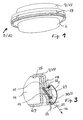
- Figur 1:
- eine räumliche Ansicht einer Fügeverbindung in verkleinerter Darstellung,
- Figur 2:
- eine Seitenansicht der Fügeverbindung von Figur 1 im Schnitt ohne Klebdichtmasse,
- Figur 3:
- eine vergrößerte Darstellung der Einzelheit X von Figur 2 mit Klebdichtmasse,
- Figur 4:
- eine Seitenansicht der ersten Seitenwand von dem ersten Bauteil von Figur 3 und
- Figur 5:
- eine Seitenansicht der zweiten Seitenwand von dem zweiten Bauteil von Figur 3.
Claims (13)
- Fügeverbindung zwischen einem ersten Bauteil (6) und einem zweiten Bauteil (7), die einander benachbarte Seitenwände (11, 18) aufweisen und die über ein mit einer entfernbaren Klebdichtmasse (1) versehbares Dichtungsbett (8) dicht miteinander verbindbar sind, dadurch gekennzeichnet, dass die erste Seitenwand (11) eine erste mit ihr verbundene Dichtfläche (15) aufweist, die im zusammengefügten Zustand in einem Abstand (22) etwa parallel zu einer zweiten Dichtfläche (21) verläuft, die mit der zweiten Seitenwand (18) verbunden ist, und dass die beiden Dichtflächen (15,21) das Dichtungsbett (8) mit einer von den Seitenwänden (11, 18) weggerichteten ebenen Verlaufsrichtung (16) bilden in deren Verlängerung die Klebdichtmasse (1) herausziehbar ist.
- Fügeverbindung nach Anspruch 1, dadurch gekennzeichnet, dass die Verlaufsrichtung (16) des Dichtungsbettes (8) gegenüber der ersten Seitenwand (11) um einen Neigungswinkel (α) geneigt ist.
- Fügeverbindung nach Anspruch 2, dadurch gekennzeichnet, dass der Neigungswinkel (α) zwischen 0° und 180° beträgt.
- Fügeverbindung nach Anspruch 3, dadurch gekennzeichnet, dass der Neigungswinkel (α) zwischen 0° und 90° beträgt.
- Fügeverbindung nach Anspruch 4, dadurch gekennzeichnet, dass der Neigungswinkel (α) ca. 30° beträgt.
- Fügeverbindung nach einem der Ansprüche 1 bis 5, dadurch gekennzeichnet, dass die beiden Bauteile (6, 7) miteinander durch den Dichtflächen (15, 21) benachbarte Verbindungsmittel (29) lagefixiert sind.
- Fügeverbindung nach einem der Ansprüche 1 bis 6, dadurch gekennzeichnet, dass die erste Seitenwand (11) mit einer an ihrem freien Ende (23) angeordneten Stirnfläche (24) gegen eine Innenfläche (25) des zweiten Bauteils (7) anschlägt und das die Stirnfläche (24) kegelige Spitzen (26) aufweist, gegen die die Innenfläche (25) des zweiten Bauteiles (7) drückbar ist.
- Fügeverbindung nach einem der Ansprüche 1 bis 7, dadurch gekennzeichnet, dass das erste Bauteil (6) als ein Scheinwerfergehäuse (10) und das zweite Bauteil (7) als eine Abdeckscheibe (17) eines Fahrzeugscheinwerfers ausgebildet ist.
- Fügeverbindung nach Anspruch 8, dadurch gekennzeichnet, dass die Abdeckscheibe (17) aus einem glasartigen Kunststoffsubstrat und das Scheinwerfergehäuse (10) aus einem thermoplastischen oder duroplastischen Kunststoffsubstrat ausgebildet ist.
- Fügeverbindung nach Anspruch 8, dadurch gekennzeichnet, dass die glasartigen Kunststoffsubstrate ausgewählt sind aus Polymethylmethacrylat, Polycarbonat oder Cycloolefincopolymer und insbesondere die thermoplastischen Kunststoffsubstrate ausgewählt sind aus Polypropylen.
- Verfahren zur Herstellung einer Fügeverbindung (5) zwischen einem ersten Bauteil (6) und einem zweiten Bauteil (7), bei dem auf einen Dichtungsbettbereich des ersten Bauteils (6) eine entfernbare Klebdichtmasse (1) in flüssigem Zustand aufgetragen und die beiden Bauteile (6, 7) zusammengefügt werden, dadurch gekennzeichnet, dass zum Entfernen der Klebdichtmasse (1) diese an einem freien Ende erfasst und in Verlängerung einer ebenen von den beiden Bauteilen (6, 7) weggerichteten Verlaufsrichtung (16) des Dichtungsbettes (8) aus diesem nahezu rückstandsfrei herausgezogen wird.
- Verfahren nach Anspruch 11, dadurch gekennzeichnet, dass die Klebdichtmasse (1) mittels einer Tankschmelzanlage mit Roboterführung auf eine am ersten Bauteil (6) angeordnete erste Dichtfläche (15) eines unteren Dichtungsbettteiles (14) des Dichtungsbettes (8) flüssig aufgetragen wird und in einem anschließenden Arbeitsgang die beiden Bauteile (6, 7) zusammengefügt werden.
- Verfahren nach Anspruch 11 oder 12, dadurch gekennzeichnet, dass nach dem Fügen des zweiten Bauteils (7) und einer kurzen Abkühlungsphase das zweite Bauteil (7) gegen das erste Bauteil (6) angedrückt und mittels Verbindungsmitteln (29) endgültig lagefixiert wird.
Applications Claiming Priority (3)
| Application Number | Priority Date | Filing Date | Title |
|---|---|---|---|
| DE19956422A DE19956422A1 (de) | 1999-11-24 | 1999-11-24 | Lösbare Klebstoffe zum Verbinden von Substraten |
| DE19956422 | 1999-11-24 | ||
| EP00125465A EP1108771B1 (de) | 1999-11-24 | 2000-11-21 | Lösbare Klebstoffe zum Verbinden von Substraten |
Related Parent Applications (1)
| Application Number | Title | Priority Date | Filing Date |
|---|---|---|---|
| EP00125465A Division EP1108771B1 (de) | 1999-11-24 | 2000-11-21 | Lösbare Klebstoffe zum Verbinden von Substraten |
Publications (3)
| Publication Number | Publication Date |
|---|---|
| EP1312461A2 true EP1312461A2 (de) | 2003-05-21 |
| EP1312461A3 EP1312461A3 (de) | 2003-06-25 |
| EP1312461B1 EP1312461B1 (de) | 2005-01-12 |
Family
ID=7930106
Family Applications (2)
| Application Number | Title | Priority Date | Filing Date |
|---|---|---|---|
| EP00125465A Expired - Lifetime EP1108771B1 (de) | 1999-11-24 | 2000-11-21 | Lösbare Klebstoffe zum Verbinden von Substraten |
| EP03000902A Expired - Lifetime EP1312461B1 (de) | 1999-11-24 | 2000-11-21 | Fügeverbindung und Verfahren zur Herstellung einer Fügeverbindung |
Family Applications Before (1)
| Application Number | Title | Priority Date | Filing Date |
|---|---|---|---|
| EP00125465A Expired - Lifetime EP1108771B1 (de) | 1999-11-24 | 2000-11-21 | Lösbare Klebstoffe zum Verbinden von Substraten |
Country Status (5)
| Country | Link |
|---|---|
| US (2) | US6858667B1 (de) |
| EP (2) | EP1108771B1 (de) |
| AT (1) | ATE266070T1 (de) |
| DE (3) | DE19956422A1 (de) |
| ES (2) | ES2236627T3 (de) |
Families Citing this family (32)
| Publication number | Priority date | Publication date | Assignee | Title |
|---|---|---|---|---|
| US7507453B2 (en) * | 2000-10-31 | 2009-03-24 | International Imaging Materials, Inc | Digital decoration and marking of glass and ceramic substrates |
| US20050087290A1 (en) * | 2002-03-08 | 2005-04-28 | Julius Herold | Method for joining transparent plastic substrates |
| WO2005108442A1 (en) * | 2002-10-15 | 2005-11-17 | Exxonmobil Chemical Patents Inc. | Polyolefin adhesive compositions and articles made therefrom |
| US7700707B2 (en) | 2002-10-15 | 2010-04-20 | Exxonmobil Chemical Patents Inc. | Polyolefin adhesive compositions and articles made therefrom |
| US7541402B2 (en) * | 2002-10-15 | 2009-06-02 | Exxonmobil Chemical Patents Inc. | Blend functionalized polyolefin adhesive |
| US7550528B2 (en) | 2002-10-15 | 2009-06-23 | Exxonmobil Chemical Patents Inc. | Functionalized olefin polymers |
| DE10248499A1 (de) * | 2002-10-17 | 2004-05-06 | Siemens Ag | Magnet-Resonanz-Tomographiegerät mit zerstörungsfrei lösbarer Bauteil-Klebeverbindung zwischen Gerätekomponenten |
| US6863944B2 (en) * | 2003-01-27 | 2005-03-08 | Building Materials Investment Corporation | Thermoplastic single ply protective covering |
| US7776603B2 (en) * | 2003-04-01 | 2010-08-17 | Cabot Corporation | Methods of specifying or identifying particulate material |
| US7776602B2 (en) | 2003-04-01 | 2010-08-17 | Cabot Corporation | Methods of providing product consistency |
| US7000457B2 (en) * | 2003-04-01 | 2006-02-21 | Cabot Corporation | Methods to control and/or predict rheological properties |
| US7776604B2 (en) * | 2003-04-01 | 2010-08-17 | Cabot Corporation | Methods of selecting and developing a particulate material |
| DE102004018047A1 (de) * | 2004-04-08 | 2005-11-10 | Tesa Ag | Verfahren zum dauerhaften Verschließen von Löchern insbesondere in Blechen oder in Kunststoffteilen von Automobilkarosserien |
| US7722713B2 (en) * | 2005-05-17 | 2010-05-25 | Cabot Corporation | Carbon blacks and polymers containing the same |
| US8268449B2 (en) * | 2006-02-06 | 2012-09-18 | Brewer Science Inc. | Thermal- and chemical-resistant acid protection coating material and spin-on thermoplastic adhesive |
| US7794832B2 (en) * | 2006-05-18 | 2010-09-14 | Neenah Paper, Inc. | Self-releasing lint tape |
| DE102006037625A1 (de) * | 2006-08-10 | 2008-02-14 | Tesa Ag | Selbstklebemasse aus hydrierten Blockcopolymeren und daraus hergestellte Schutzfolie für glatte Oberflächen |
| DE102006037627A1 (de) * | 2006-08-10 | 2008-02-14 | Tesa Ag | Selbstklebemasse aus hydrierten Blockcopolymeren und daraus hergestellte Schutzfolie für glatte und raue Oberflächen |
| US20080200011A1 (en) * | 2006-10-06 | 2008-08-21 | Pillalamarri Sunil K | High-temperature, spin-on, bonding compositions for temporary wafer bonding using sliding approach |
| CN101779268B (zh) | 2007-06-25 | 2013-11-06 | 布鲁尔科技公司 | 高温旋涂暂时性粘合组合物 |
| DE102008020880A1 (de) * | 2008-04-25 | 2009-10-29 | Hella Kgaa Hueck & Co. | Fügeverbindung für ein Gehäuse |
| US20110183100A1 (en) * | 2008-05-09 | 2011-07-28 | Lee Dae-Woo | Solvent-free adhesive for waterproof sheet, waterproof sheet and manufacturing method of waterproof sheet using the solvent-free adhesive and construction method using the waterproof sheet |
| US8092628B2 (en) * | 2008-10-31 | 2012-01-10 | Brewer Science Inc. | Cyclic olefin compositions for temporary wafer bonding |
| US8771927B2 (en) * | 2009-04-15 | 2014-07-08 | Brewer Science Inc. | Acid-etch resistant, protective coatings |
| JP2013091774A (ja) * | 2011-10-05 | 2013-05-16 | Canon Inc | エポキシ樹脂組成物 |
| CN102911626B (zh) * | 2012-11-29 | 2015-08-12 | 无锡市万力粘合材料有限公司 | 粘鼠用热熔胶组合物及其制备方法 |
| DE102013206624A1 (de) * | 2013-04-15 | 2014-10-16 | Tesa Se | Haftklebemasse und Verwendung derselben in einem Haftklebstreifen |
| AU2014293082B2 (en) | 2013-07-24 | 2018-05-10 | Dow Global Technologies Llc | Adhesive compositions containing functionalized ethylene/alpha-olefin interpolymers and rosin-based tackifiers |
| EP3074477B1 (de) * | 2013-11-25 | 2017-06-28 | Basell Poliolefine Italia S.r.l. | Heissgeschmolzene klebstoffzusammensetzung auf polyolefinbasis |
| BR112016013719B1 (pt) | 2013-12-26 | 2022-07-12 | Dow Global Technologies Llc | Composição e artigo |
| WO2019210120A1 (en) * | 2018-04-27 | 2019-10-31 | Avery Dennison Corporation | Non-swelling hot melt adhesive |
| CN112292364B (zh) * | 2018-06-25 | 2023-07-28 | 巴斯夫欧洲公司 | 用于形成粘结结合或用于化学锚固的两组分体系 |
Family Cites Families (20)
| Publication number | Priority date | Publication date | Assignee | Title |
|---|---|---|---|---|
| DE1604736A1 (de) | 1966-08-25 | 1971-01-14 | Siemens Ag | Verfahren zum Verbinden von Teilen aus Kunststoff |
| US3987122A (en) | 1972-04-03 | 1976-10-19 | Exxon Research And Engineering Company | Thermoplastic adhesive compositions |
| US4009793A (en) | 1974-07-12 | 1977-03-01 | The Procter & Gamble Company | Tamper-proof closure seal |
| US4024312A (en) | 1976-06-23 | 1977-05-17 | Johnson & Johnson | Pressure-sensitive adhesive tape having extensible and elastic backing composed of a block copolymer |
| US4305996A (en) * | 1980-03-10 | 1981-12-15 | The B. F. Goodrich Company | Hydroxyl-containing liquid polymers and adhesives made therefrom |
| US4461633A (en) | 1982-09-28 | 1984-07-24 | Continental Conveyor & Equipment Co., Inc. | Air filtering machinery with variable speed cleaning |
| DE3331016A1 (de) * | 1983-04-06 | 1984-10-11 | Beiersdorf Ag, 2000 Hamburg | Klebfolie fuer wiederloesbare klebbindungen |
| WO1986002055A1 (fr) | 1984-10-05 | 1986-04-10 | Cod Inter Techniques S.A. | Emballage etanche, procede de fabrication et utilisation de cet emballage |
| DE3925068A1 (de) * | 1989-07-28 | 1991-02-07 | Schmalbach Lubeca | Zwei- oder dreiteiliger behaelter, insb. aus blech |
| US5470622A (en) | 1990-11-06 | 1995-11-28 | Raychem Corporation | Enclosing a substrate with a heat-recoverable article |
| US5516581A (en) | 1990-12-20 | 1996-05-14 | Minnesota Mining And Manufacturing Company | Removable adhesive tape |
| JP2662488B2 (ja) | 1992-12-04 | 1997-10-15 | 株式会社小糸製作所 | 自動車用灯具における前面レンズ脚部とシール溝間のシール構造 |
| DE4339604C2 (de) | 1993-11-20 | 1996-06-05 | Beiersdorf Ag | Verwendung eines Klebfolien-Abschnitts für eine wiederablösbare Verklebung |
| CA2201291A1 (en) | 1994-09-30 | 1996-04-11 | Achilles Chiotis | Silicone sealing material exhibiting high stress relaxation |
| DE19504425A1 (de) * | 1995-02-10 | 1996-08-14 | Hella Kg Hueck & Co | Heißschmelzklebstoffe für Fahrzeugleuchten und Fahrzeugscheinwerfer |
| US5827591A (en) | 1996-10-08 | 1998-10-27 | Tricor Direct, Inc. | Removable adhesive notes for an industrial setting |
| DE19649727A1 (de) | 1996-11-30 | 1998-06-04 | Beiersdorf Ag | Klebeband |
| CN1104480C (zh) | 1997-01-30 | 2003-04-02 | 三井化学株式会社 | 热熔粘合剂组合物 |
| US5870955A (en) | 1997-03-05 | 1999-02-16 | Presstek, Inc. | Lithographic printing system with reusable support surfaces and lithographic constructions for use therewith |
| DE19739114A1 (de) * | 1997-09-06 | 1999-03-11 | Hella Kg Hueck & Co | Scheinwerfer für Fahrzeuge |
-
1999
- 1999-11-24 DE DE19956422A patent/DE19956422A1/de not_active Ceased
-
2000
- 2000-11-20 US US09/715,138 patent/US6858667B1/en not_active Expired - Fee Related
- 2000-11-21 AT AT00125465T patent/ATE266070T1/de not_active IP Right Cessation
- 2000-11-21 EP EP00125465A patent/EP1108771B1/de not_active Expired - Lifetime
- 2000-11-21 DE DE50006316T patent/DE50006316D1/de not_active Expired - Lifetime
- 2000-11-21 EP EP03000902A patent/EP1312461B1/de not_active Expired - Lifetime
- 2000-11-21 ES ES03000902T patent/ES2236627T3/es not_active Expired - Lifetime
- 2000-11-21 ES ES00125465T patent/ES2218050T3/es not_active Expired - Lifetime
- 2000-11-21 DE DE50009245T patent/DE50009245D1/de not_active Expired - Lifetime
-
2002
- 2002-02-07 US US10/067,196 patent/US20020173582A1/en not_active Abandoned
Also Published As
| Publication number | Publication date |
|---|---|
| EP1108771A2 (de) | 2001-06-20 |
| ES2218050T3 (es) | 2004-11-16 |
| ES2236627T3 (es) | 2005-07-16 |
| DE50006316D1 (de) | 2004-06-09 |
| DE19956422A1 (de) | 2001-06-13 |
| ATE266070T1 (de) | 2004-05-15 |
| US6858667B1 (en) | 2005-02-22 |
| EP1108771A3 (de) | 2002-09-11 |
| EP1108771B1 (de) | 2004-05-06 |
| EP1312461A3 (de) | 2003-06-25 |
| US20020173582A1 (en) | 2002-11-21 |
| EP1312461B1 (de) | 2005-01-12 |
| DE50009245D1 (de) | 2005-02-17 |
Similar Documents
| Publication | Publication Date | Title |
|---|---|---|
| EP1312461B1 (de) | Fügeverbindung und Verfahren zur Herstellung einer Fügeverbindung | |
| DE69601741T2 (de) | Glasscheibe, insbesondere für Kraftfahrzeuge, prepariert zum Montieren durch Klebung | |
| DE69528279T2 (de) | Druckmittelbetätigte dichtung für radiale luftfilter | |
| EP3292604B1 (de) | Verfahren zum herstellen einer wanddurchführung für mehrere kabel sowie anordnung | |
| DE69804369T2 (de) | Klappverdeckeinrichtung und Vorrichtung zu deren Herstellung | |
| DE69413125T2 (de) | Dichtungsstreifen für bewegbares Kraftfahrzeugfenster | |
| DE102011050752B4 (de) | Scheibeneinheit eines Fahrzeugfensters, insbesondere eines Seitenfensters | |
| EP1294552A1 (de) | Verfahren zur herstellung eines hybridteils | |
| EP2450240B1 (de) | Mehrteilige Blendenleiste | |
| DE19848246A1 (de) | Thermoplastteil mit eingespritzter Elastomerdichtung | |
| DE602005002868T2 (de) | Kraftfahrzeugrahmenanordnung | |
| DE2853767A1 (de) | Verfahren zum abdichten von leuchten oder scheinwerfern von kraftfahrzeugen o.dgl. | |
| DE102009006439A1 (de) | Scheinwerferbefestigung an einem Fahrzeug | |
| EP0825052B1 (de) | Befestigung einer Fensterscheibe in einem Kraftfahrzeug | |
| DE102017128814A1 (de) | Befestigungsvorrichtung | |
| EP2213406B1 (de) | Sensorgehäuse | |
| EP2335958A1 (de) | Klemmhalter sowie Scheibenbaugruppe mit einem solchen Klemmhalter und Verfahren zur Herstellung einer solchen Scheibenbaugruppe | |
| DE102020111741A1 (de) | Zierteil für ein Kraftfahrzeug und Verfahren zu dessen Herstellung | |
| EP2998144A1 (de) | Fahrzeug mit dichtungsprofil | |
| DE10336378A1 (de) | Luft-Filter, insbesondere Kfz-Innenraumfilter | |
| EP4122732B1 (de) | Fahrzeugscheibenanordnung und transportschutzleiste zur verwendung bei einer fahrzeugscheibenanordnung | |
| DE4425362A1 (de) | Verfahren für die Verbindung von zwei Teilen eines Gehäuses und entsprechende Gehäuse,insbesondere für eine Klima-, Heizungs- und/oder Belüftungsanlage von Kraftfahrzeugen | |
| EP3358093B1 (de) | Überlauf- oder ablaufbaugruppe und verfahren zum montieren einer überlauf- oder ablaufbaugruppe an einem becken | |
| DE19504828A1 (de) | Verfahren zum Herstellen und Verbinden eines Rahmens mit einer Glasscheibe und Vorrichtung zum Durchführen des Verfahrens | |
| EP2760604B1 (de) | Abdichtungseinrichtung für eine rohbauöffnung einer klappe, insbesondere einer heckklappe eines kraftfahrzeugs |
Legal Events
| Date | Code | Title | Description |
|---|---|---|---|
| PUAI | Public reference made under article 153(3) epc to a published international application that has entered the european phase |
Free format text: ORIGINAL CODE: 0009012 |
|
| PUAL | Search report despatched |
Free format text: ORIGINAL CODE: 0009013 |
|
| AC | Divisional application: reference to earlier application |
Ref document number: 1108771 Country of ref document: EP Kind code of ref document: P |
|
| AK | Designated contracting states |
Designated state(s): AT BE CH CY DE DK ES FI FR GB GR IE IT LI LU MC NL PT SE TR |
|
| AX | Request for extension of the european patent |
Extension state: AL LT LV MK RO SI |
|
| AK | Designated contracting states |
Designated state(s): AT BE CH CY DE DK ES FI FR GB GR IE IT LI LU MC NL PT SE TR |
|
| AX | Request for extension of the european patent |
Extension state: AL LT LV MK RO SI |
|
| 17P | Request for examination filed |
Effective date: 20031106 |
|
| 17Q | First examination report despatched |
Effective date: 20031210 |
|
| GRAP | Despatch of communication of intention to grant a patent |
Free format text: ORIGINAL CODE: EPIDOSNIGR1 |
|
| AKX | Designation fees paid |
Designated state(s): DE ES FR IT |
|
| GRAS | Grant fee paid |
Free format text: ORIGINAL CODE: EPIDOSNIGR3 |
|
| RAP1 | Party data changed (applicant data changed or rights of an application transferred) |
Owner name: HELLA KGAA HUECK & CO. |
|
| GRAA | (expected) grant |
Free format text: ORIGINAL CODE: 0009210 |
|
| AC | Divisional application: reference to earlier application |
Ref document number: 1108771 Country of ref document: EP Kind code of ref document: P |
|
| AK | Designated contracting states |
Kind code of ref document: B1 Designated state(s): DE ES FR IT |
|
| REF | Corresponds to: |
Ref document number: 50009245 Country of ref document: DE Date of ref document: 20050217 Kind code of ref document: P |
|
| REG | Reference to a national code |
Ref country code: IE Ref legal event code: FG4D Free format text: GERMAN |
|
| REG | Reference to a national code |
Ref country code: ES Ref legal event code: FG2A Ref document number: 2236627 Country of ref document: ES Kind code of ref document: T3 |
|
| PLBE | No opposition filed within time limit |
Free format text: ORIGINAL CODE: 0009261 |
|
| STAA | Information on the status of an ep patent application or granted ep patent |
Free format text: STATUS: NO OPPOSITION FILED WITHIN TIME LIMIT |
|
| ET | Fr: translation filed | ||
| 26N | No opposition filed |
Effective date: 20051013 |
|
| PGFP | Annual fee paid to national office [announced via postgrant information from national office to epo] |
Ref country code: IT Payment date: 20061130 Year of fee payment: 7 |
|
| PG25 | Lapsed in a contracting state [announced via postgrant information from national office to epo] |
Ref country code: IT Free format text: LAPSE BECAUSE OF NON-PAYMENT OF DUE FEES Effective date: 20071121 |
|
| PGFP | Annual fee paid to national office [announced via postgrant information from national office to epo] |
Ref country code: ES Payment date: 20091201 Year of fee payment: 10 |
|
| PGFP | Annual fee paid to national office [announced via postgrant information from national office to epo] |
Ref country code: FR Payment date: 20091123 Year of fee payment: 10 |
|
| REG | Reference to a national code |
Ref country code: FR Ref legal event code: ST Effective date: 20110801 |
|
| PG25 | Lapsed in a contracting state [announced via postgrant information from national office to epo] |
Ref country code: FR Free format text: LAPSE BECAUSE OF NON-PAYMENT OF DUE FEES Effective date: 20101130 |
|
| REG | Reference to a national code |
Ref country code: ES Ref legal event code: FD2A Effective date: 20120110 |
|
| PG25 | Lapsed in a contracting state [announced via postgrant information from national office to epo] |
Ref country code: ES Free format text: LAPSE BECAUSE OF NON-PAYMENT OF DUE FEES Effective date: 20101122 |
|
| PGFP | Annual fee paid to national office [announced via postgrant information from national office to epo] |
Ref country code: DE Payment date: 20131113 Year of fee payment: 14 |
|
| REG | Reference to a national code |
Ref country code: DE Ref legal event code: R119 Ref document number: 50009245 Country of ref document: DE |
|
| PG25 | Lapsed in a contracting state [announced via postgrant information from national office to epo] |
Ref country code: DE Free format text: LAPSE BECAUSE OF NON-PAYMENT OF DUE FEES Effective date: 20150602 |