EP1308613B1 - Calculateur du degré d'ouverture d'un papillon - Google Patents
Calculateur du degré d'ouverture d'un papillon Download PDFInfo
- Publication number
- EP1308613B1 EP1308613B1 EP02024199A EP02024199A EP1308613B1 EP 1308613 B1 EP1308613 B1 EP 1308613B1 EP 02024199 A EP02024199 A EP 02024199A EP 02024199 A EP02024199 A EP 02024199A EP 1308613 B1 EP1308613 B1 EP 1308613B1
- Authority
- EP
- European Patent Office
- Prior art keywords
- zero point
- point detection
- value
- detection value
- throttle valve
- Prior art date
- Legal status (The legal status is an assumption and is not a legal conclusion. Google has not performed a legal analysis and makes no representation as to the accuracy of the status listed.)
- Expired - Lifetime
Links
- 238000001514 detection method Methods 0.000 claims description 270
- 238000000034 method Methods 0.000 claims description 20
- 230000005540 biological transmission Effects 0.000 description 21
- 230000007423 decrease Effects 0.000 description 3
- 238000010586 diagram Methods 0.000 description 3
- 230000001133 acceleration Effects 0.000 description 2
- 230000002159 abnormal effect Effects 0.000 description 1
- 238000002485 combustion reaction Methods 0.000 description 1
- 230000000994 depressogenic effect Effects 0.000 description 1
- 239000000446 fuel Substances 0.000 description 1
- 238000002347 injection Methods 0.000 description 1
- 239000007924 injection Substances 0.000 description 1
Images


Classifications
-
- F—MECHANICAL ENGINEERING; LIGHTING; HEATING; WEAPONS; BLASTING
- F02—COMBUSTION ENGINES; HOT-GAS OR COMBUSTION-PRODUCT ENGINE PLANTS
- F02D—CONTROLLING COMBUSTION ENGINES
- F02D11/00—Arrangements for, or adaptations to, non-automatic engine control initiation means, e.g. operator initiated
- F02D11/06—Arrangements for, or adaptations to, non-automatic engine control initiation means, e.g. operator initiated characterised by non-mechanical control linkages, e.g. fluid control linkages or by control linkages with power drive or assistance
- F02D11/10—Arrangements for, or adaptations to, non-automatic engine control initiation means, e.g. operator initiated characterised by non-mechanical control linkages, e.g. fluid control linkages or by control linkages with power drive or assistance of the electric type
- F02D11/106—Detection of demand or actuation
-
- F—MECHANICAL ENGINEERING; LIGHTING; HEATING; WEAPONS; BLASTING
- F02—COMBUSTION ENGINES; HOT-GAS OR COMBUSTION-PRODUCT ENGINE PLANTS
- F02D—CONTROLLING COMBUSTION ENGINES
- F02D2250/00—Engine control related to specific problems or objectives
- F02D2250/16—End position calibration, i.e. calculation or measurement of actuator end positions, e.g. for throttle or its driving actuator
Definitions
- the present invention relates to a throttle valve opened amount calculator.
- a throttle valve opened amount sensor detects the opened amount of a throttle valve, which is arranged in an intake passage and opened and closed in accordance with the depressed amount of an acceleration pedal.
- the opened amount of the throttle valve is used as a parameter to perform engine control, such as fuel injection and ignition adjustment.
- the throttle valve opened amount is used as a parameter for controlling distribution of the drive force of a transmission installed in the vehicle.
- the throttle valve opened amount ⁇ is calculated as described below.
- the CPU uses map data of the throttle valve opened amount ⁇ corresponding to the absolute value TPA to obtain the throttle valve opened amount ⁇ corresponding to the present detection voltage (absolute value TPA).
- the throttle valve opened amount ⁇ is obtained from the absolute value TPA for the following reason.
- the zero point detection value TPV0 differs between sensors (e.g., 0.6 ⁇ 0.2V). Accordingly, the zero point detection value TPV0 is obtained for each throttle valve sensor and the absolute value TPA is obtained from the zero point detection value TPV0.
- the zero point detection value TPV0 is obtained in accordance with the absolute value TPA, errors that result from differences between sensors are prevented and the throttle valve opened amount ⁇ is accurately obtained. In this state, the same map data for obtaining the throttle valve opened amount ⁇ is used for every automobile even though there may be differences between throttle valve sensors.
- the CPU periodically corrects the zero point detection value TPV0.
- the CPU sets the detection voltage TPV as a new zero point detection value TPV.
- the CPU obtains the throttle valve opened amount ⁇ in accordance with the updated zero point detection value TPV0. Accordingly, the zero point detection value TPV0 is replaced by a smaller value whenever the detection voltage TPV is less than the zero point detection value TPV0.
- the zero point detection value TPV0 is immediately updated with the detection voltage TPV.
- the CPU may set the detection voltage TPV as the new zero point detection value TPV0.
- the drive force transmission of a four wheel drive vehicle is normally separated from the throttle valve sensor, which is controlled by an engine controller.
- the signal line of the sensor is long and is apt to being affected by noise. Consequently, the zero point detection value TPV0 may be updated when not necessary.
- a throttle valve opened amount calculator includes a valve sensor for detecting an opened amount of a throttle valve to generate a detection voltage.
- a memory is connected to the valve sensor to store an initial zero point detection value.
- the initial zero point detection value is the detection voltage output from the throttle valve sensor when the throttle valve is fully closed.
- a calculation circuit is connected to the valve sensor and the memory to obtain the difference between the detection voltage and the initial zero point detection value and to calculate the opened amount of the throttle valve with the difference.
- the calculation circuit calculates a new zero point detection value that is greater than a smallest one of the plurality of detection voltages by a predetermined value and updates the initial zero point detection value with the new zero point detection value.
- a method for calculating an opened amount of a throttle valve includes detecting the opened amount of the throttle valve to generate a detection voltage, storing an initial zero point detection value in a memory, and calculating the opened amount of the throttle valve from a difference between the detection voltage and the initial zero point detection value.
- the initial zero point detection value is the detection voltage when the throttle valve is fully closed.
- a new zero point detection value that is greater than a smallest one of the plurality of detection voltages by a predetermined value is calculated.
- the initial zero point detection value is updated with the new zero point detection value.
- a throttle valve opened amount calculator is applied to a drive force transmission control circuit 50 of a four wheel drive vehicle 100.
- Fig. 1 is a schematic diagram of the four wheel drive vehicle 100 in which the drive force transmission control circuit 50 is incorporated.
- the four wheel drive vehicle 100 includes an internal combustion engine 2 and a transaxle 3.
- the transaxle 3 includes a transmission 3a, a front differential 3b, and a transfer 3c.
- a left front axle 4a and a right front axle 4b are connected to the transaxle 3.
- Front wheels 5a, 5b are mounted on the front axles 4a, 4b, respectively.
- the transaxle 3 transmits the drive force produced by the engine 2 to the front axles 4a, 4b.
- the front axles 4a, 4b further transmit the drive force to the front wheels 5a, 5b.
- the transfer 3c is connected to a propeller shaft 6, which is further connected to a drive force transmission 7.
- a drive pinion shaft 8 connects the drive force transmission 7 to a rear differential 9.
- the rear differential 9 is connected to left and right rear axles 10a, 10b.
- Rear wheels 11a, 11b are mounted on the rear axles 10a, 10b, respectively.
- the drive force generated by the engine 2 is transmitted to the drive force transmission 7 by the transfer 3c and the propeller shaft 6. Further, the drive force is transmitted to the drive pinion shaft 8, the rear differential 9, and the rear axles 10a, 10b from the drive force transmission 7 to rotate the rear wheels 11a, 11b.
- the drive force transmission 7 has a wet multiplate electromagnetic clutch mechanism.
- the electromagnetic clutch mechanism includes a plurality of separable clutch plates (not shown) and an electromagnetic coil.
- the electromagnetic force generated by the electromagnetic coil, which is incorporated in the drive force transmission 7, causes the clutch plates to frictionally engage each other. In this state, the drive force of the engine 2 that is transmitted to the drive force transmission 7 is transmitted from the propeller shaft 6 to the drive pinion shaft 8.
- the drive force transmitted to the drive pinion shaft 8 increases as the frictional engaging force of the clutch plates increases.
- the frictional engaging force of the clutch plates is determined by the value of the current supplied to the electromagnetic coil 7a.
- the drive force transmission 7 controls the frictional engaging force to select either one of a four wheel drive state or a two wheel drive state and to control the drive force distribution rate between the front wheels 5a, 5b and the rear wheels 11a, 11b in the four wheel drive state.
- a drive force transmission control circuit (throttle valve opened amount calculator) 50 which controls the drive force transmission 7, will now be discussed with reference to Fig. 2 .
- the drive force transmission control circuit 50 includes a drive force distribution controller (electronic control unit, ECU) 21 and a throttle valve sensor 33.
- the drive force distribution controller 21 includes a CPU 22, which serves as a calculation circuit, a ROM 23, a RAM 24, and an input/output circuit 25.
- the CPU 22 performs various calculations to control the electromagnetic coil 7a of the drive force transmission 7 in accordance with various types of programs stored in the ROM 23.
- the ROM 23 stores various programs, which control the electromagnetic coil 7a, various types of daLa, and various types of map data. In addition to storing various types of data, the RAM 23 temporarily stores calculation results of the CPU 22.
- the control programs stored in the ROM 23 are used to calculate the value of the current supplied to the electromagnetic coil 7a in accordance with the present driven state of the automobile and to control the electromagnetic coil 7a by means of the input/output circuit 25 in accordance with the calculated current value.
- the ROM 23 stores a program for calculating the opened amount ⁇ of a throttle valve and a program for correcting a zero point detection value TPV0, which is used to calculate the opened amount ⁇ .
- the map data stored in the ROM 23 is used to perform four wheel drive.
- the ROM 23 stores map data related to duty ratio control of the electromagnetic coil 7a.
- the map data related to the duty ratio is used to produce the frictional engaging force (target frictional engaging force) corresponding to the drive force distribution rate that is optimal under the present driving state.
- a left front wheel velocity sensor 31a, a right front wheel velocity sensor 31b, a left rear wheel velocity sensor 32a, and a right rear wheel velocity sensor 32b are connected to the CPU 22 via input/output circuit 25.
- the left front wheel velocity sensor 31a detects the wheel velocity of the left front wheel 5a.
- the right front wheel velocity sensor 31b detects the wheel velocity of the right front wheel 5b.
- the front wheel velocity sensors 31a, 31b generate detection signals corresponding to the present velocity of the left front wheel 5a and the right front wheel 5b, respectively, and send the detection signals to the input/output circuit 25.
- the left rear wheel velocity sensor 32a detects the wheel velocity of the left rear wheel 11a
- the right rear wheel velocity sensor 32b detects the wheel velocity of the right rear wheel 11b.
- the rear wheel velocity sensors 32a, 32b generate detection signals corresponding to the present velocity of the left rear wheel 11a and the right rear wheel 11b, respectively, and send the detection signals to the input/output circuit 25.
- the CPU 22 calculates the present wheel velocities VFL, VFR, VRL, VRR of the wheels 5a, 5b, 11a, 11b from the detection signals of the wheel velocity sensors 31a, 31b, 32a, 32b, respectively.
- the CPU 22 calculates the front wheel average velocity VFN ((VFL+VFR)/2) from the wheel velocities VFL, VFR and calculates the rear wheel average velocity VRN ((VRL+VRR)/2) from the wheel velocities VRL, VRR.
- the CPU 22 calculates a differential velocity ⁇ N(
- the CPU 22 obtains the vehicle velocity from the wheel velocities VFL, VFR, VRL, VRR.
- a throttle valve sensor 33 which detects the opened amount ⁇ of the throttle valve of the engine 2, is connected to the CPU 22 via the input/output circuit 25.
- the throttle valve sensor 33 is controlled by an engine controller (not shown).
- the throttle valve sensor 33 generates a detection signal (detection voltage) TPV corresponding to the throttle valve opened amount ⁇ and provides the CPU 22 with the detection voltage TPV via the input/output circuit 25.
- the throttle valve opens and closes in accordance with the depression of an acceleration pedal (not shown).
- the CPU 22 uses the detection voltage TPV to calculate the throttle valve opened amount ⁇ as described below.
- the CPU 22 subtracts a predetermined reference value (zero point detection value TPV0) from the detection voltage TPV to obtain an absolute value TPA (TPV-TPV0).
- the zero point detection value TPV0 is updated periodically and stored in the RAM 24.
- the CPU 22 uses map data of the throttle valve opened amount ⁇ corresponding to the absolute value TPA, which is stored in the ROM 23, to obtain the throttle valve opened amount ⁇ corresponding to the present detection voltage (absolute value TPA).
- the CPU 22 calculates the optimal drive force distribution rate using map data, which is stored in the ROM 23, in accordance with the throttle valve opened amount ⁇ , the differential velocity ⁇ N, and the vehicle velocity.
- the CPU 22 generates a current generation signal, which determines the current value of the electromagnetic coil 7a, in accordance with the calculation result. More specifically, the CPU 22 generates a current generation signal to obtain the duty ratio resulting in a drive force distribution rate that is optimal for the present driven state of the automobile in accordance with the map data stored in the ROM 23.
- the CPU 22 is connected to a drive circuit 35, which controls the electromagnetic force of the electromagnetic coil 7a incorporated in the drive force transmission 7, via the input/output circuit 25.
- the drive force 35 generates drive current having a predetermined value and supplies the electromagnetic coil 7a of the drive force transmission 7 with the generated current. Accordingly, the drive force transmission 7 properly controls the drive force distribution rate.
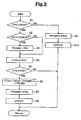
- the correction of the zero point detection value TPV0, which is used to calculate the throttle valve opened amount ⁇ for the drive force transmission control circuit (throttle valve opened amount calculator) 50 will now be discussed with reference to the flowchart of Fig. 3 .
- the CPU 22 periodically performs the process illustrated in the flowchart of Fig. 3 .
- the CPU 22 retrieves the detection voltage TPV and compares the detection voltage TPV with the zero point detection value TPV0, which is stored in the RAM 24 (step S1). When the detection voltage TPV is less than the zero point detection value TPV0, the CPU 22 proceeds to step S2 and compares the detection voltage TPV with a minimum detection voltage value TPVMIN, which is stored in the RAM 24 (step S2).
- the CPU 22 sets the detected detection voltage TPV as the new minimum detection voltage value TPVMIN and rewrites the minimum detection voltage value TPVMIN (step S3). Afterward, the CPU 22 proceeds to step S4. At step S2, if the detection voltage TPV is greater than the minimum detection voltage value TPVMIN, the CPU 22 proceeds to step S4 without rewriting the minimum detection voltage value TPVMIN.
- the minimum detection voltage value TPVMIN is set at the value of the zero point detection value TPV0 when the initial value is set.
- step S4 the CPU 22 adds "1" to a zero point detection counter value CT0, which is stored in the RAM 24, and than compares the zero point detection counter value CT0 with a reference detection number KT0 (step S5).
- the reference detection number KT0 which is stored in the ROM 23, is the number of times the detection voltage TPV is successively less than the zero point detection value TPV0. In the preferred embodiment, when the number of times in which the detection voltage TPV is less than the zero point detection value TPV0 reaches the reference detection number KT0 within a predetermined period, the zero point detection value TPV0 is corrected.
- step S5 when the zero point detection counter value CT0 is less than the reference detection number KT0, the CPU 22 temporarily terminates the process. Accordingly, when the detection voltage TPV being less than the zero point detection value TPV0 is successively detected for a number of times that is less than the reference detection value KT0 and the detection voltage TPV is less than the minimum detection voltage value TPV, the smallest detection voltage TPV is stored in the RAM 24 as the minimum detection voltage value TPVMIN (steps S2, S3).
- the CPU 22 When the zero point detection counter value CT0 reaches the reference detection number KT0, the CPU 22 performs a calculation to correct the zero point detection value (step S6).
- the correction calculation is performed based on formula (1) using the zero point detection value TPV0 and the minimum detection voltage value TPVMIN. TPV ⁇ 0 - TPV ⁇ 0 - TPVMIN / a + TPVMIN
- the difference between the zero point detection value TPV0 and the minimum detection voltage value TPVMIN is divided by two and the minimum detection voltage value TPVMIN is added to the divided difference.
- the CPU 22 sets the calculation result as the new zero point detection value TPV0 and rewrites the former zero point detecLion value TPV0. The CPU 22 then uses the new zero point detection value TPV0 to calculate the throttle valve opened amount ⁇ .
- the CPU 22 sets the new zero point detection value TPV0 as the minimum detection voltage value TPVMIN (step S7) and resets the zero point detection counter value CT0 to "0" (step S8). Afterward, the CPU 22 temporarily terminates the correction process.
- step S1 If the detection voltage TPV is greater than the zero point detection value TPV0 is step S1, the CPU 22 proceeds to step S9 and sets the zero point detection value TPV0, which is stored in the RAM 24, as the minimum detection voltage value TPVMIN. Then, the CPU 22 resets the zero point detection counter CT0 to "0" (step S10) and temporarily terminates the process.
- the minimum detection voltage value TPVMIN is replaced by the present zero point detection value TPV0 when the detection voltage TPV is detected as being greater than the zero point detection value TPV0. Accordingly, an erroneous minimum detection voltage value TPVMIN is not used to calculate the new zero point detection value TPV0.
- the throttle valve opened amount calculator 50 has the advantages described below.
- the constant "a” may be a value that is "1" or greater.
- the reference detection number KT0 may be a value in which the detection voltage TPV is only less than the zero point detection value TPV0 during the predetermined time.
- the voltage value of the second smallest detection voltage TPV may be used to correct the zero point detection value TPV0.
- the average value of a plurality of detection voltages TPV which are smaller than the zero point detection value TPV0, may be calculated to update the zero point detection value TPV0 with the average value of the detection voltage TPV.
- the average value of the detection voltage TPV may be calculated without the smallest detection voltage TPV.
- the present invention may be embodied in a front engine rear drive (FR) or rear engine rear drive (RR) based four wheel drive vehicle.
- FR front engine rear drive
- RR rear engine rear drive
- a calculator for calculating an opened amount of a throttle valve with high accuracy regardless of voltage fluctuation and noise includes a valve sensor (33) for detecting the opened amount of the throttle valve to generate a detection voltage.
- a memory (24) stores an initial zero point detection value.
- a calculation circuit (22) obtains the difference between the detection voltage and the initial zero point detection value and calculates the opened amount of the throttle valve with the difference. When a plurality of detection voltages that arc less than the initial zero point detection value are generated, the calculation circuit (22) calculates a new zero point detection value that is greater than a smallest one of the plurality of detection voltages by a predetermined value and updates the initial zero point detection value with the new zero point detection value.
Landscapes
- Engineering & Computer Science (AREA)
- Chemical & Material Sciences (AREA)
- Combustion & Propulsion (AREA)
- Mechanical Engineering (AREA)
- General Engineering & Computer Science (AREA)
- Combined Controls Of Internal Combustion Engines (AREA)
- Indication Of The Valve Opening Or Closing Status (AREA)
- Magnetically Actuated Valves (AREA)
- Length Measuring Devices With Unspecified Measuring Means (AREA)
Claims (18)
- Calculateur de degré d'ouverture de papillon des gaz comprenant un capteur de papillon (33) destiné à détecter un degré d'ouverture d'un papillon des gaz afin de générer une tension de détection, une mémoire (24) reliée au capteur de papillon afin de stocker une valeur de détection de point zéro initiale, la valeur de détection de point zéro initiale étant la tension de détection délivrée par le capteur de papillon des gaz quand le papillon des gaz est entièrement fermé, et un circuit de calcul (22) relié au capteur de papillon et à la mémoire afin d'obtenir la différence entre la tension de détection et la valeur de détection de point zéro initiale et de calculer le degré d'ouverture du papillon des gaz avec la différence, le calculateur de degré d'ouverture de papillon étant caractérisé par :quand une multiplicité de tensions de détection qui sont inférieures à la valeur de détection de point zéro initiale est générée, le circuit de calcul (22) est prévu pour calculer une nouvelle valeur de détection de point zéro qui est plus grande qu'une plus petite tension de la multiplicité de tensions de détection d'une valeur prédéterminée et pour mettre à jour la valeur de détection de point zéro initiale avec la nouvelle valeur de détection de point zéro, sur la base de la plus petite tension de la multiplicité de tensions de détection en ajoutant une valeur prédéterminée à la plus petite tension de la multiplicité de tensions de détection.
- Calculateur selon la revendication 1, caractérisé en ce que le circuit de calcul est prévu pour obtenir une tension différentielle entre la plus petite tension de la multiplicité de tensions de détection et la valeur de détection de point zéro initiale, pour diviser la tension différentielle par une valeur prédéterminée, et pour ajouter la tension différentielle divisée à la plus petite tension de la multiplicité de tensions de détection afin de calculer la nouvelle valeur de détection de point zéro.
- Calculateur selon la revendication 1, caractérisé en ce que le circuit de calcul est prévu pour obtenir une valeur moyenne de la multiplicité de tensions de détection et pour établir la valeur moyenne comme nouvelle valeur de détection de point zéro.
- Calculateur selon la revendication 1, caractérisé en ce que le circuit de calcul est prévu pour utiliser des tensions de détection à l'exclusion de la plus petite tension de la multiplicité de tensions de détection afin de calculer la nouvelle valeur de détection de point zéro.
- Calculateur selon la revendication 4, caractérisé en ce que le circuit de calcul est prévu pour obtenir une valeur moyenne des tensions de détection à l'exclusion de la plus petite tension de la multiplicité de tensions de détection et pour établir la valeur moyenne comme nouvelle valeur de détection de point zéro.
- Calculateur selon la revendication 1, caractérisé en ce que le circuit de calcul est prévu pour calculer la nouvelle valeur de détection de point zéro quand les tensions de la multiplicité de tensions de détection sont détectées de manière successive.
- Calculateur selon l'une quelconque des revendications 1 à 6, caractérisé en ce que le circuit de calcul est prévu pour calculer la nouvelle valeur de détection de point zéro quand la multiplicité de tensions de détection est détectée au cours d'une période prédéterminée.
- Calculateur selon la revendication 1, caractérisé en ce que le circuit de calcul est prévu pour calculer la nouvelle valeur de détection de point zéro quand un nombre prédéterminé de tensions de détection qui sont plus petites que la valeur de détection de point zéro initiale est détecté de manière successive.
- Calculateur selon la revendication 8, caractérisé en ce que le circuit de calcul est prévu pour calculer la nouvelle valeur de détection de point zéro quand le nombre prédéterminé de tensions de détection est détecté au cours d'une période prédéterminée.
- Procédé de calcul d'un degré d'ouverture d'un papillon des gaz, le procédé comprenant les étapes de détection du degré d'ouverture du papillon des gaz afin de générer une tension de détection, de stockage d'une valeur de détection de point zéro initiale dans une mémoire, la valeur de détection de point zéro initiale étant la tension de détection quand le papillon des gaz est entièrement fermé, et de calcul du degré d'ouverture du papillon des gaz à partir de la différence entre la tension de détection et la valeur de détection de point zéro initiale, le procédé étant caractérisé en ce que :l'étape de calcul comprend les étapes consistant à : quand une multiplicité de tensions de détection qui sont inférieures à la valeur de détection de point zéro initiale est générée, calculer une nouvelle valeur de détection de point zéro qui est plus grande qu'une plus petite tension de la multiplicité de tensions de détection d'une valeur prédéterminée, et mettre à jour la valeur de détection de point zéro initiale avec la nouvelle valeur de détection de point zéro, sur la base de la plus petite tension de la multiplicité de tensions de détection en ajoutant une valeur prédéterminée à la plus petite tension de la multiplicité de tensions de détection.
- Procédé selon la revendication 10, caractérisé en ce que l'étape de calcul de la nouvelle valeur de détection de point zéro comprend les étapes consistant à :obtenir une tension différentielle entre la plus petite tension de la multiplicité de tensions de détection et la valeur de détection de point zéro initiale ;diviser la tension différentielle avec une valeur prédéterminée afin de calculer une tension différentielle divisée, etajouter la tension différentielle divisée à la plus petite tension de la multiplicité de tensions de détection afin de calculer la nouvelle valeur de détection de point zéro.
- Procédé selon la revendication 10, caractérisé en ce que l'étape de calcul de la nouvelle valeur de détection de point zéro comprend les étapes consistant à :obtenir une valeur moyenne de la multiplicité de tensions de détection ; etétablir la valeur moyenne comme nouvelle valeur de détection de point zéro.
- Procédé selon la revendication 10, caractérisé en ce que l'étape de calcul de la nouvelle valeur de détection de point zéro comprend les étapes consistant à:utiliser les tensions de détection à l'exclusion de la plus petite tension de la multiplicité de tensions de détection afin de calculer la nouvelle valeur de détection de point zéro.
- Procédé selon la revendication 13, caractérisé en ce que l'étape de calcul de la nouvelle valeur de détection de point zéro comprend :l'obtention d'une valeur moyenne des tensions de détection à l'exclusion de la plus petite tension de la multiplicité de tensions de détection ; etl'établissement de la valeur moyenne comme nouvelle valeur de détection de point zéro.
- Procédé selon la revendication 10, caractérisé en ce que l'étape de calcul de la nouvelle valeur de détection de point zéro comprend le fait de calculer la nouvelle valeur de détection de point zéro quand les tensions de la multiplicité de tensions de détection sont détectées de manière successive.
- Procédé selon l'une quelconque des revendications 10 à 15, caractérisé en ce que l'étape de calcul de la nouvelle valeur de détection de point zéro comprend le fait de calculer la nouvelle valeur de détection de point zéro quand la multiplicité de tensions de détection est détectée au cours d'une période prédéterminée.
- Procédé selon la revendication 10, caractérisé en ce que l'étape de calcul de la nouvelle valeur de détection de point zéro comprend le fait de calculer la nouvelle valeur de détection de point zéro quand un nombre prédéterminé de tensions de détection qui sont plus petites que la valeur de détection de point zéro initiale est détecté de manière successive.
- Procédé selon la revendication 17, caractérisé en ce que l'étape de calcul de la nouvelle valeur de détection de point zéro comprend le fait de calculer la nouvelle valeur de détection de point zéro quand le nombre prédéterminé de tensions de détection est détecté au cours d'une période prédéterminée.
Applications Claiming Priority (2)
| Application Number | Priority Date | Filing Date | Title |
|---|---|---|---|
| JP2001333714A JP2003139528A (ja) | 2001-10-31 | 2001-10-31 | スロットルバルブ開度演算装置 |
| JP2001333714 | 2001-10-31 |
Publications (3)
| Publication Number | Publication Date |
|---|---|
| EP1308613A2 EP1308613A2 (fr) | 2003-05-07 |
| EP1308613A3 EP1308613A3 (fr) | 2006-05-03 |
| EP1308613B1 true EP1308613B1 (fr) | 2009-04-01 |
Family
ID=19148936
Family Applications (1)
| Application Number | Title | Priority Date | Filing Date |
|---|---|---|---|
| EP02024199A Expired - Lifetime EP1308613B1 (fr) | 2001-10-31 | 2002-10-30 | Calculateur du degré d'ouverture d'un papillon |
Country Status (4)
| Country | Link |
|---|---|
| US (1) | US6708106B2 (fr) |
| EP (1) | EP1308613B1 (fr) |
| JP (1) | JP2003139528A (fr) |
| DE (1) | DE60231781D1 (fr) |
Cited By (1)
| Publication number | Priority date | Publication date | Assignee | Title |
|---|---|---|---|---|
| US11614047B2 (en) * | 2016-02-25 | 2023-03-28 | Kohler Co. | Electronic fuel injection system and method for engines |
Families Citing this family (2)
| Publication number | Priority date | Publication date | Assignee | Title |
|---|---|---|---|---|
| CN112918483B (zh) * | 2021-03-18 | 2022-03-22 | 天津易鼎丰动力科技有限公司 | 纯电动汽车加速踏板自学习的方法 |
| CN116670487A (zh) * | 2021-12-28 | 2023-08-29 | 宁德时代新能源科技股份有限公司 | 一种油门踏板的开度计算方法、装置、整车控制器和车辆 |
Family Cites Families (5)
| Publication number | Priority date | Publication date | Assignee | Title |
|---|---|---|---|---|
| JPS58122326A (ja) * | 1982-01-14 | 1983-07-21 | Honda Motor Co Ltd | 内燃エンジンの絞り弁アイドル開度検出方法 |
| JPH0799202B2 (ja) * | 1986-08-11 | 1995-10-25 | アイシン・エィ・ダブリュ株式会社 | 電子制御式自動変速機 |
| JP2525412B2 (ja) * | 1987-06-11 | 1996-08-21 | マツダ株式会社 | エンジンのスロットル弁開度検出装置 |
| JP3084929B2 (ja) * | 1992-06-01 | 2000-09-04 | 株式会社デンソー | スロットル基準開度検出装置 |
| JP3393741B2 (ja) * | 1995-08-23 | 2003-04-07 | 三菱電機株式会社 | エンジンのスロットル開度検出装置 |
-
2001
- 2001-10-31 JP JP2001333714A patent/JP2003139528A/ja active Pending
-
2002
- 2002-10-30 DE DE60231781T patent/DE60231781D1/de not_active Expired - Lifetime
- 2002-10-30 EP EP02024199A patent/EP1308613B1/fr not_active Expired - Lifetime
- 2002-10-31 US US10/284,147 patent/US6708106B2/en not_active Expired - Fee Related
Cited By (1)
| Publication number | Priority date | Publication date | Assignee | Title |
|---|---|---|---|---|
| US11614047B2 (en) * | 2016-02-25 | 2023-03-28 | Kohler Co. | Electronic fuel injection system and method for engines |
Also Published As
| Publication number | Publication date |
|---|---|
| US6708106B2 (en) | 2004-03-16 |
| JP2003139528A (ja) | 2003-05-14 |
| EP1308613A2 (fr) | 2003-05-07 |
| US20030083800A1 (en) | 2003-05-01 |
| EP1308613A3 (fr) | 2006-05-03 |
| DE60231781D1 (de) | 2009-05-14 |
Similar Documents
| Publication | Publication Date | Title |
|---|---|---|
| US6789017B2 (en) | Vehicle steering angle position determination method | |
| KR940010691B1 (ko) | 차량의 출력제어장치 | |
| EP0440365B1 (fr) | Procédé et appareil pour déterminer la position neutre d'angle de braquage d'un véhicule | |
| US7395142B2 (en) | Counter steer detecting method | |
| EP1452382B1 (fr) | Dispositif de commande de distribution de couple pour véhicule à quatre roues motrices | |
| EP1749726B1 (fr) | Dispositif et méthode pour la distribution de la force motrice | |
| EP1749725B1 (fr) | Dispositif et méthode pour la distribution de la force motrice | |
| US8000877B2 (en) | Fuel economy system and method for a vehicle | |
| EP1308613B1 (fr) | Calculateur du degré d'ouverture d'un papillon | |
| US7357208B2 (en) | Control system for an at least temporarily four wheel-driven motor vehicle | |
| US20030109978A1 (en) | Power distribution control apparatus for four-wheel drive vehicle | |
| US4908764A (en) | System and method for automatically controlling a vehicle speed to a desired cruising speed | |
| JP4831929B2 (ja) | 車輌の駆動力制御装置 | |
| JP6013564B1 (ja) | 車速制御装置 | |
| EP2418113B1 (fr) | Appareil d'affichage de stabilité | |
| JPH072135A (ja) | 電動式パワーステアリング装置 | |
| US20060113135A1 (en) | Control system for a vehicle with at least part-time four-wheel drive | |
| JPH1118210A (ja) | ハイブリッドシステム車両の制御装置 | |
| JP4416986B2 (ja) | 燃料噴射装置 | |
| US8474567B2 (en) | Method for calibrating an actuator of an all-wheel drive clutch | |
| EP0562515B1 (fr) | Dispositif de changement de vitesse pour une transmission automatique de véhicule | |
| EP4310454A1 (fr) | Compensation de décalage de vitesse de rotation | |
| JP4915083B2 (ja) | 車両の駆動力配分制御装置 | |
| JP2004144670A (ja) | 車速検出装置 | |
| JP5029860B2 (ja) | 車両の駆動力配分制御装置 |
Legal Events
| Date | Code | Title | Description |
|---|---|---|---|
| PUAI | Public reference made under article 153(3) epc to a published international application that has entered the european phase |
Free format text: ORIGINAL CODE: 0009012 |
|
| AK | Designated contracting states |
Designated state(s): AT BE BG CH CY CZ DE DK EE ES FI FR GB GR IE IT LI LU MC NL PT SE SK TR |
|
| AX | Request for extension of the european patent |
Extension state: AL LT LV MK RO SI |
|
| PUAL | Search report despatched |
Free format text: ORIGINAL CODE: 0009013 |
|
| AK | Designated contracting states |
Kind code of ref document: A3 Designated state(s): AT BE BG CH CY CZ DE DK EE ES FI FR GB GR IE IT LI LU MC NL PT SE SK TR |
|
| AX | Request for extension of the european patent |
Extension state: AL LT LV MK RO SI |
|
| RAP1 | Party data changed (applicant data changed or rights of an application transferred) |
Owner name: JTEKT CORPORATION |
|
| RIN1 | Information on inventor provided before grant (corrected) |
Inventor name: WAKAO, HISAAKI Inventor name: MORI, YUTAKE |
|
| 17P | Request for examination filed |
Effective date: 20061019 |
|
| AKX | Designation fees paid |
Designated state(s): DE FR GB |
|
| 17Q | First examination report despatched |
Effective date: 20061221 |
|
| GRAP | Despatch of communication of intention to grant a patent |
Free format text: ORIGINAL CODE: EPIDOSNIGR1 |
|
| RIN1 | Information on inventor provided before grant (corrected) |
Inventor name: WAKAO, HISAAKI Inventor name: MORI, YUTAKA |
|
| GRAS | Grant fee paid |
Free format text: ORIGINAL CODE: EPIDOSNIGR3 |
|
| GRAA | (expected) grant |
Free format text: ORIGINAL CODE: 0009210 |
|
| AK | Designated contracting states |
Kind code of ref document: B1 Designated state(s): DE FR GB |
|
| REG | Reference to a national code |
Ref country code: GB Ref legal event code: FG4D |
|
| REF | Corresponds to: |
Ref document number: 60231781 Country of ref document: DE Date of ref document: 20090514 Kind code of ref document: P |
|
| PLBE | No opposition filed within time limit |
Free format text: ORIGINAL CODE: 0009261 |
|
| STAA | Information on the status of an ep patent application or granted ep patent |
Free format text: STATUS: NO OPPOSITION FILED WITHIN TIME LIMIT |
|
| 26N | No opposition filed |
Effective date: 20100105 |
|
| PG25 | Lapsed in a contracting state [announced via postgrant information from national office to epo] |
Ref country code: GB Free format text: LAPSE BECAUSE OF NON-PAYMENT OF DUE FEES Effective date: 20091030 |
|
| PGFP | Annual fee paid to national office [announced via postgrant information from national office to epo] |
Ref country code: DE Payment date: 20101027 Year of fee payment: 9 |
|
| PGFP | Annual fee paid to national office [announced via postgrant information from national office to epo] |
Ref country code: FR Payment date: 20111103 Year of fee payment: 10 |
|
| REG | Reference to a national code |
Ref country code: FR Ref legal event code: ST Effective date: 20130628 |
|
| PG25 | Lapsed in a contracting state [announced via postgrant information from national office to epo] |
Ref country code: DE Free format text: LAPSE BECAUSE OF NON-PAYMENT OF DUE FEES Effective date: 20130501 |
|
| REG | Reference to a national code |
Ref country code: DE Ref legal event code: R119 Ref document number: 60231781 Country of ref document: DE Effective date: 20130501 |
|
| PG25 | Lapsed in a contracting state [announced via postgrant information from national office to epo] |
Ref country code: FR Free format text: LAPSE BECAUSE OF NON-PAYMENT OF DUE FEES Effective date: 20121031 |