EP1308591B1 - Hinge - Google Patents
Hinge Download PDFInfo
- Publication number
- EP1308591B1 EP1308591B1 EP02021585A EP02021585A EP1308591B1 EP 1308591 B1 EP1308591 B1 EP 1308591B1 EP 02021585 A EP02021585 A EP 02021585A EP 02021585 A EP02021585 A EP 02021585A EP 1308591 B1 EP1308591 B1 EP 1308591B1
- Authority
- EP
- European Patent Office
- Prior art keywords
- arm
- folding
- hinge
- fixing
- hinge according
- Prior art date
- Legal status (The legal status is an assumption and is not a legal conclusion. Google has not performed a legal analysis and makes no representation as to the accuracy of the status listed.)
- Expired - Lifetime
Links
Images


Classifications
-
- E—FIXED CONSTRUCTIONS
- E05—LOCKS; KEYS; WINDOW OR DOOR FITTINGS; SAFES
- E05D—HINGES OR SUSPENSION DEVICES FOR DOORS, WINDOWS OR WINGS
- E05D3/00—Hinges with pins
- E05D3/06—Hinges with pins with two or more pins
- E05D3/12—Hinges with pins with two or more pins with two parallel pins and one arm
-
- E—FIXED CONSTRUCTIONS
- E05—LOCKS; KEYS; WINDOW OR DOOR FITTINGS; SAFES
- E05D—HINGES OR SUSPENSION DEVICES FOR DOORS, WINDOWS OR WINGS
- E05D3/00—Hinges with pins
- E05D3/06—Hinges with pins with two or more pins
-
- E—FIXED CONSTRUCTIONS
- E05—LOCKS; KEYS; WINDOW OR DOOR FITTINGS; SAFES
- E05D—HINGES OR SUSPENSION DEVICES FOR DOORS, WINDOWS OR WINGS
- E05D15/00—Suspension arrangements for wings
- E05D15/26—Suspension arrangements for wings for folding wings
- E05D15/264—Suspension arrangements for wings for folding wings for bi-fold wings
-
- E—FIXED CONSTRUCTIONS
- E05—LOCKS; KEYS; WINDOW OR DOOR FITTINGS; SAFES
- E05F—DEVICES FOR MOVING WINGS INTO OPEN OR CLOSED POSITION; CHECKS FOR WINGS; WING FITTINGS NOT OTHERWISE PROVIDED FOR, CONCERNED WITH THE FUNCTIONING OF THE WING
- E05F1/00—Closers or openers for wings, not otherwise provided for in this subclass
- E05F1/08—Closers or openers for wings, not otherwise provided for in this subclass spring-actuated, e.g. for horizontally sliding wings
- E05F1/10—Closers or openers for wings, not otherwise provided for in this subclass spring-actuated, e.g. for horizontally sliding wings for swinging wings, e.g. counterbalance
- E05F1/12—Mechanisms in the shape of hinges or pivots, operated by springs
- E05F1/1246—Mechanisms in the shape of hinges or pivots, operated by springs with a coil spring perpendicular to the pivot axis
- E05F1/1253—Mechanisms in the shape of hinges or pivots, operated by springs with a coil spring perpendicular to the pivot axis with a compression spring
-
- E—FIXED CONSTRUCTIONS
- E05—LOCKS; KEYS; WINDOW OR DOOR FITTINGS; SAFES
- E05Y—INDEXING SCHEME RELATING TO HINGES OR OTHER SUSPENSION DEVICES FOR DOORS, WINDOWS OR WINGS AND DEVICES FOR MOVING WINGS INTO OPEN OR CLOSED POSITION, CHECKS FOR WINGS AND WING FITTINGS NOT OTHERWISE PROVIDED FOR, CONCERNED WITH THE FUNCTIONING OF THE WING
- E05Y2800/00—Details, accessories and auxiliary operations not otherwise provided for
- E05Y2800/40—Protection
- E05Y2800/41—Protection against finger injury
-
- E—FIXED CONSTRUCTIONS
- E05—LOCKS; KEYS; WINDOW OR DOOR FITTINGS; SAFES
- E05Y—INDEXING SCHEME RELATING TO HINGES OR OTHER SUSPENSION DEVICES FOR DOORS, WINDOWS OR WINGS AND DEVICES FOR MOVING WINGS INTO OPEN OR CLOSED POSITION, CHECKS FOR WINGS AND WING FITTINGS NOT OTHERWISE PROVIDED FOR, CONCERNED WITH THE FUNCTIONING OF THE WING
- E05Y2900/00—Application of doors, windows, wings or fittings thereof
- E05Y2900/10—Application of doors, windows, wings or fittings thereof for buildings or parts thereof
- E05Y2900/13—Application of doors, windows, wings or fittings thereof for buildings or parts thereof characterised by the type of wing
- E05Y2900/132—Doors
-
- Y—GENERAL TAGGING OF NEW TECHNOLOGICAL DEVELOPMENTS; GENERAL TAGGING OF CROSS-SECTIONAL TECHNOLOGIES SPANNING OVER SEVERAL SECTIONS OF THE IPC; TECHNICAL SUBJECTS COVERED BY FORMER USPC CROSS-REFERENCE ART COLLECTIONS [XRACs] AND DIGESTS
- Y10—TECHNICAL SUBJECTS COVERED BY FORMER USPC
- Y10S—TECHNICAL SUBJECTS COVERED BY FORMER USPC CROSS-REFERENCE ART COLLECTIONS [XRACs] AND DIGESTS
- Y10S16/00—Miscellaneous hardware, e.g. bushing, carpet fastener, caster, door closer, panel hanger, attachable or adjunct handle, hinge, window sash balance
- Y10S16/43—Hinge mounting bracket
Definitions
- the invention relates to a hinge for a folding flap with a first folding element and a second folding element which in a closed position on a common vertical plane are arranged, for connecting the first folding element with the second folding element comprising a fastening element, a first Arm and a second arm.
- the fastener has a first mounting surface with which it to the first folding element fitting can be fastened.
- the first arm is around a first Swivel axis between a first position and a second position pivotally connected to the fastener.
- the second arm has attachment means on, with which the second arm can be fastened to the second folding element. furthermore it is about a second pivot axis, which is arranged parallel to the first pivot axis is pivotable between a first position and a second position connected to the first arm. In a closed position, the folding elements in each case one abutting edge, which are arranged parallel to one another.
- Such a hinge is shown in FR 1 508 270 with a fastener that has a has first mounting surface and is attachable to a first door. Further the hinge has a first arm pivotable about a pivot axis is connected to the fastening element. Furthermore, a second arm is provided, which can be fastened via fastening means with a second door leaf. About that In addition, the second arm is pivotable about a second pivot axis with the first Arm connected.
- hinges include a first fastener fixedly attached to a surface of the first pleat member and a second fastener fixedly attached to a surface of the second pleat member.
- the two fastening elements are pivotally connected to each other about a pivot axis, which extends along the abutting edges of the folding elements.
- Problems occur when fold flaps and folding doors which are asymmetrical foldably to each other, that is, in which the pivot axis does not extend close to the joint edges, but in which the pivot axis relative to the surface of one of Fa l tele elements displaced parallel to the joint edges is arranged.
- an arm of the first fastening element projects in the plane of the folding element beyond the respective abutment edge.
- the first fastener is pivotally connected to the second fastener.
- the pivot axis has approximately the same distance to the abutting edge of the first folding element as to the second folding element.
- the object of the present invention is to provide a hinge which is asymmetrical Split flaps or folding doors can be used without for A person is in danger of getting hurt if the folding door or the folding door is closed.
- the object is achieved by an aforementioned hinge, wherein the first arm in the first position, which occupies this in the closed position and an open position of the folding lid, a smallest angle to the mounting surface, the first arm in the second position, which assumes this in an intermediate position of the folding lid, enclosing a largest angle to the mounting surface, in the first position of the second arm, which occupies this in the closed position of the Faltdeckels, the first arm and the second arm the smallest angle to each other and include in the second position of the second arm, which occupies this in the open position of the Faltdeckels, the first arm and the second arm enclose the largest angle to each other.
- this hinge in a folding flap or a folding door can thus, starting from a closed position in which the two folding elements on a common Lie flat and the first arm in its first position and the second arm in its first position, the abutting edge of the first folding element is from the second Folding be moved away, the first arm transferred to its second position is and is slightly pivoted relative to the second arm.
- the abutting edge of the first folding element and the abutting edge of the second Folding a gap.
- the first arm starting from the first pivot axis, a lever be formed, by means of a spring element is supported against the fastener.
- the lever serves as a stop against the fastener.
- a simple structure of the hinge especially in a Manufacture of the hinge made of plastic, can be ensured be that the first arm by means of a film hinge is connected to the fastening element.
- a separate spring element can be avoided by the fact that the film hinge is resilient and thus as spring means serves.
- the lock slider achieved with the control contour when the first arm in his second position is convicted, a constant distance to the first pivot axis. This will ensure that the lock slider only when moving out of the Locking recess must be moved against a spring force. in the further course of the pivoting path of the first arm to the second Position, the lock slider is no longer against the spring force moved, so that no torque exerted on the first arm becomes.
- the second attachment means are by a second attachment surface shown, with which the second Arm can be fastened to the second folding element.
- first mounting surface and the second attachment surface is arranged on a common plane, when the first arm in the first position and the second arm is in the first position.
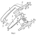
- FIG. 1 shows the individual parts of a hinge according to the invention in an exploded view
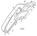
- Figure 2 shows the inventive Hinge in assembled state.
- Figures 1 and 2 will be described together below.
- the hinge comprises a fastening element 1, on which a first arm 2 pivotally mounted about a first pivot axis 3 is. With the first arm 2 is a second arm 4 pivotally a second pivot axis 5 is connected.
- the fastening element 1 has a first fastening plate 6, which forms a first fastening surface 7.
- the fastener 1 can be at a first folding a Fold the flap or a folding door, with the first mounting surface 7 on a surface of the first folding element is applied.
- To the fastener 1 against rotation on the To secure the surface of the first folding element are outgoing formed by the first mounting surface 7 securing lugs 8, which dip into a hole in the first folding element can.
- the first mounting plate 6 also has through holes 9, through the fastening screws inserted can be.
- the fastener 1 at the one side facing away from the first attachment surface 7 Joint approach 10, which provided with an opening 11 is.
- the first arm 2 is U-shaped in profile, with a first leg 12 and a second leg 13 of the U-shaped Profiles in the mounted state of the first arm 2, the joint approach 10 enclose.
- a bore 14 which are aligned with the opening 11 in the hinge extension 10.
- a hinge pin 15 sits in the holes 14 and the opening 11, so that the first arm 2 and the fastener 1 pivotally connected to each other.
- a lever 16 is formed.
- a coil spring 17 relies on the one hand against the lever 16 and on the other hand against the fastener 1 from.
- the coil spring 17 is inside a bore 18 is guided in the hinge extension 10 and supports against the bottom of the bore 16 from.
- the first arm 2 is thus biased toward a first position, in the first arm 2 a smallest angle to the first mounting surface 7 takes.
- the first arm 2 can be out of this Position against the spring force of the coil spring 17 in a second Transfer position in which the first arm 2 a largest Angle to the first mounting surface 7 occupies.
- the lever 16 is like the entire first arm 2 U-shaped design and forms Support surfaces 19, 20, which in the second position of the first Arms 2 are supported against the first mounting plate 6. Thus, the pivotal path of the first arm 2 is limited.
- the second arm 4 has a connecting portion 22, in a bore 23 is provided.
- the bore 23 is coaxial arranged to the second pivot axis 5.
- the first leg 12 and the second leg 13 of the first arm 2 enclose the Connecting portion 22, wherein bores 24 in the two Legs 12, 13 with the bore 23 of the connecting portion 22 are aligned.
- In the holes 24 and the bore 23 is seated second hinge pin 21, so that the first arm 2 and the second Arm 4 are pivotally connected together.
- the illustrated Position is the second arm 4 in a first Position relative to the first arm 2, in which the first arm second and the second arm 4 occupy a smallest angle to each other.
- the second arm 4 has a fastening section 25.
- the second mounting plate 26 With the second mounting plate 26, the second arm 4 on a second folding element the folding flap or the folding door are attached, wherein the second attachment surface 27 on a surface of the second Folding element rests.
- Securing lugs 28 molded, which in the assembled state of Hinge protrude into holes of the second folding element.
- FIG. 3 shows a folding flap with a first folding element 30 and a second folding member 31 vertically stacked are arranged.
- the first folding element 30 is at its vertical the upper end pivotally connected to a body of a piece of furniture.
- a hinge according to Figures 1 and 2 is attached. Matching components of the hinge are given the same reference numerals provided and described in Figures 1 and 2.
- the second attachment surface 27 of the second attachment plate 26 is flat against the first surface 32.
- a second surface 33 of the second folding element 31 is the fastening element 1 attached.
- the first attachment surface 7 of the fastener 1 lies flat on a second Surface 33 of the second folding element 31 at.
- the folding elements 31, 32nd in a normal position of the closed position.
- the first attachment surface 7 and the second attachment surface 27 on a common plane.
- the second pivot axis 5 at a distance to a first abutting edge 34 of the first folding element 30 and to a second abutting edge 35 of the second folding element 31 is arranged.
- the two abutting edges 34, 35 of the folding elements 30, 31 run parallel to each other.
- the pivot axis is approximately equal to the two abutting edges of Folding elements.
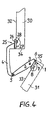
- FIG. 4 shows the folding flap according to FIG. 3 in an anti-pinch position the closed position.
- the first folding element 30 is in the same position as in Figure 3.
- the first arm 2 is transferred to its second position, in which he the largest angle to the first mounting surface. 7 of the fastener 1 occupies.
- the first arm 2 and the second arm 4 in an intermediate position to each other, in which the two arms 2, 4 a larger angle enclose each other as shown in Figure 3.
- the mounting surface 7 of the fastener 1 and the mounting surface 27 of the second attachment plate 26 are thereby arranged at an angle to each other; as well as the first Surface 32 of the first folding element 30 and the second surface 33 of the second folding element 31.
- the two abutting edges 34, 35 of the folding elements 30, 31 a gap, which is big enough that a person with his fingers can reach into the gap without jamming.
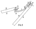
- FIG. 5 shows the folding flap according to FIG. 3 in an open position.
- the first arm 2 is in his first position in which he has the same angular position to Fastener 1 occupies as in the closed position according to Figure 3.
- the second arm 4 is located relative to the first Arm 2 in its second position, in which the two arms 2, 4 take the biggest angle to each other.
- the second folding element 31 is thus about the pivot axis 5 to the first folding element 30 folded up, wherein the first folding element 30 to the Swivel axis to which it is connected to the body of the furniture is, is pivoted upwards.
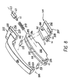
- FIG. 6 shows a further embodiment of a hinge.
- Components associated with components of the hinge according to the figures 1 to match 5, are provided with reference numerals to are increased to 100, and described in Figures 1 to 5.
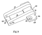
- FIG. 6 is described below together with FIG. 7, the first arm 102 in a different perspective shows.
- the Fastener 101 and the first arm 102 are integrally formed.
- the fastener 101 and the first arm 102nd are integral with the fastener via film hinges 36 101 connected.
- the film hinges 27 serve for a to, the first arm 102 hinged to the fastener 101 to connect.
- the film hinge 36 is elastic formed so that the first arm 102 toward his first position is charged.
- the first arm 102 has a first rib 37 and a second rib 38, which in each case via the film hinges 36 are connected to the fastener 101 and the in Direction of the second pivot axis 5 spaced from each other are.
- the first rib 37 and the second rib 38 are further connected by a web 39 with each other.
- the first rib 37, the second rib 38 and the web 39 thus form a recess, into the first arm 104 in its first position can dive.
- the first arm 104 is in this case both with the first rib 37 as well as the second rib 38 of the first Arms 102 pivotally connected. This will be an embodiment allows starting from the first mounting surface 107 has a lower height. Also let the components are made of plastic.
- FIG. 8 shows the individual parts of a further embodiment a hinge according to the invention in an exploded view.
- a lock slider 40 is displaceable guided. This is supported by a coil spring 217 against the second arm 204 from.
- the lock slider 40 a Centering lug 41, which in the turns of the coil spring 217 is led into it.
- the lock slider 40 has further a footprint 43, with the lock slider 40th by means of the coil spring 217 against a setting contour 44 of the fastening element 201 is supported. In the first position of the first arm 202 engages the lock slider 40 with his Footprint 43 in a locking recess 45 a.
- the setting contour 44 has, starting from the latching recess 45, a constant Distance from the first pivot axis 203, so that when pivoting the first arm 202 to the second position of the lock slider 40 is not moved against the spring force of the coil spring 217 must be so that no torque on the first arm 202th is exercised.
- the lock slider 40 Located in the second position of the first arm 202 the lock slider 40 in abutment with an end stop 46 of the adjusting contour 44.
Abstract
Description
Die Erfindung betrifft ein Scharnier für eine Faltklappe mit einem ersten Faltelement und einem zweiten Faltelements, die in einer geschlossenen Stellung auf einer gemeinsamen vertikalen Ebene angeordnet sind, zum Verbinden des ersten Faltelements mit dem zweiten Faltelement umfassend ein Befestigungselement, einen ersten Arm und einen zweiten Arm.The invention relates to a hinge for a folding flap with a first folding element and a second folding element which in a closed position on a common vertical plane are arranged, for connecting the first folding element with the second folding element comprising a fastening element, a first Arm and a second arm.
Das Befestigungselement weist eine erste Befestigungsfläche auf, mit der es an dem ersten Faltelement anliegend befestigbar ist. Der erste Arm ist um eine erste Schwenkachse zwischen einer ersten Position und einer zweiten Position schwenkbar mit dem Befestigungselement verbunden. Der zweite Arm weist Befestigungsmittel auf, mit denen der zweite Arm an dem zweiten Faltelement befestigbar ist. Femer ist er um eine zweite Schwenkachse, die parallel zur ersten Schwenkachse angeordnet ist, zwischen einer ersten Stellung und einer zweiten Stellung schwenkbar mit dem ersten Arm verbunden. In einer geschlossenen Position weisen die Faltelemente jeweils eine Stoßkante auf, die parallel zueinander angeordnet sind.The fastener has a first mounting surface with which it to the first folding element fitting can be fastened. The first arm is around a first Swivel axis between a first position and a second position pivotally connected to the fastener. The second arm has attachment means on, with which the second arm can be fastened to the second folding element. furthermore it is about a second pivot axis, which is arranged parallel to the first pivot axis is pivotable between a first position and a second position connected to the first arm. In a closed position, the folding elements in each case one abutting edge, which are arranged parallel to one another.
Ein solches Scharnier zeigt FR 1 508 270 mit einem Befestigungselement, das eine
erste Befestigungsfläche aufweist und an einem ersten Türflügel befestigbar ist. Ferner
weist das Scharnier einen ersten Arm auf, der um eine Schwenkachse schwenkbar
mit dem Befestigungselement verbunden ist. Ferner ist ein zweiter Arm vorgesehen,
der über Befestigungsmittel mit einem zweiten Türflügel befestigbar ist. Darüber
hinaus ist der zweite Arm um eine zweite Schwenkachse schwenkbar mit dem ersten
Arm verbunden. Such a hinge is shown in
Andere bekannte Scharniere umfassen ein erstes Befestigungselement, das an einer Oberfläche des ersten Faltelements fest angebracht ist, und ein zweites Befestigungselement, das an einer Oberfläche des zweiten Faltelements fest angebracht ist. Die beiden Befestigungselemente sind um eine Schwenkachse schwenkbar miteinander verbunden, welche entlang der Stoßkanten der Faltelemente verläuft. Probleme treten bei Faltklappen und Falttüren auf, die asymmetrisch zueinander faltbar sind, das heißt, bei denen die Schwenkachse nicht nahe der Stoßkanten verläuft, sondern bei denen die Schwenkachse bezogen auf die Oberfläche eines der Faltelemente zu den Stoßkanten parallel versetzt angeordnet ist. Hierbei steht bei bekannten Scharnieren ein Arm des ersten Befestigungselements in Faltelementenebene über die jeweilige Stoßkante vor. An einem freien Ende des Arms ist das erste Befestigungselement schwenkbar mit dem zweiten Befestigungselement verbunden. Hierbei weist die Schwenkachse etwa den gleichen Abstand zur Stoßkante des ersten Faltelements wie zum zweiten Faltelement auf. Beim Öffnen der Faltklappe oder der Falttür entsteht somit ein Spalt zwischen den beiden Faltelementen. Dieser Spalt bildet eine Gefahrenquelle beim Schließen, da eine Person in den Spalt greifen und sich die Hand beim Schließen klemmen kann.Other known hinges include a first fastener fixedly attached to a surface of the first pleat member and a second fastener fixedly attached to a surface of the second pleat member. The two fastening elements are pivotally connected to each other about a pivot axis, which extends along the abutting edges of the folding elements. Problems occur when fold flaps and folding doors which are asymmetrical foldably to each other, that is, in which the pivot axis does not extend close to the joint edges, but in which the pivot axis relative to the surface of one of Fa l tele elements displaced parallel to the joint edges is arranged. In this case, in known hinges, an arm of the first fastening element projects in the plane of the folding element beyond the respective abutment edge. At a free end of the arm, the first fastener is pivotally connected to the second fastener. In this case, the pivot axis has approximately the same distance to the abutting edge of the first folding element as to the second folding element. When opening the folding flap or the folding door thus creates a gap between the two folding elements. This gap is a source of danger when closing, as a person can reach into the gap and pinch his hand when closing.
Aufgabe der vorliegenden Erfindung ist es, ein Scharnier zu schaffen, das für asymmetrisch geteilte Faltklappen oder Falttüren eingesetzt werden kann, ohne dass für eine Person die Gefahr besteht sich zu verletzen, wenn die Faltklappe oder die Falttür geschlossen wird.The object of the present invention is to provide a hinge which is asymmetrical Split flaps or folding doors can be used without for A person is in danger of getting hurt if the folding door or the folding door is closed.
Erfindungsgemäß wird die Aufgabe durch ein eingangs genanntes Scharnier gelöst,
wobei der erste Arm in der ersten Position, die dieser in der Schließstellung und einer
Offenstellung des Faltdeckels einnimmt, einen kleinsten Winkel zur Befestigungsfläche
einschließt,
der erste Arm in der zweiten Position, die dieser in einer Zwischenstellung des Faltdeckels
einnimmt, einen größten Winkel zur Befestigungsfläche einschließt,
in der ersten Stellung des zweiten Arms, die dieser in der Schließstellung des Faltdeckels
einnimmt, der erste Arm und der zweite Arm den kleinsten Winkel zueinander
einschließen und
in der zweiten Stellung des zweiten Arms, die dieser in der Offenstellung des Faltdeckels
einnimmt, der erste Arm und der zweite Arm den größten Winkel zueinander
einschließen.According to the invention the object is achieved by an aforementioned hinge, wherein the first arm in the first position, which occupies this in the closed position and an open position of the folding lid, a smallest angle to the mounting surface,
the first arm in the second position, which assumes this in an intermediate position of the folding lid, enclosing a largest angle to the mounting surface,
in the first position of the second arm, which occupies this in the closed position of the Faltdeckels, the first arm and the second arm the smallest angle to each other and include
in the second position of the second arm, which occupies this in the open position of the Faltdeckels, the first arm and the second arm enclose the largest angle to each other.
Bei Einsatz dieses Scharniers in einer Faltklappe oder einer Falttür kann somit, ausgehend von einer Schließposition, in der die beiden Faltelemente auf einer gemeinsamen Ebene liegen und der erste Arm in seiner ersten Position und der zweite Arm in seiner ersten Stellung ist, die Stoßkante des ersten Faltelements vom zweiten Faltelement weg bewegt werden, wobei der erste Arm in seine zweite Position überführt wird und geringfügig gegenüber dem zweiten Arm verschwenkt wird. Somit entsteht zwischen der Stoßkante des ersten Faltelements und der Stoßkante des zweiten Faltelements ein Spalt. Beim Schließen der Faltklappe oder der Falttür kann dieser Spalt in der Schließstellung erhalten bleiben, so dass eine Person, die in den Spalt gegriffen hat, sich nicht verletzt.When using this hinge in a folding flap or a folding door can thus, starting from a closed position in which the two folding elements on a common Lie flat and the first arm in its first position and the second arm in its first position, the abutting edge of the first folding element is from the second Folding be moved away, the first arm transferred to its second position is and is slightly pivoted relative to the second arm. Thus arises between the abutting edge of the first folding element and the abutting edge of the second Folding a gap. When closing the folding door or the folding door this can Gap in the closed position, so that a person in the closed position Gap has seized, not hurt.
Um zu gewährleisten, dass die beiden Faltelemente im Normalzustand der Schließstellung, dass heißt wenn kein Handeingriff und somit kein Spalt zwischen den Faltelementen gegeben ist, auf einer gemeinsamen Ebene angeordnet sind, ist der erste Arm mittels Federmittel zu seiner ersten Position hin beaufschlagt.In order to ensure that the two folding elements in the normal state of the closed position, that means if there is no manual intervention and thus no gap between the folding elements is given, are arranged on a common plane, is the first Arm acted upon by spring means to its first position.
Hierzu kann dem ersten Arm ausgehend von der ersten Schwenkachse ein Hebel angeformt sein, der mittels eines Federelements gegen das Befestigungselement abgestützt ist.For this purpose, the first arm, starting from the first pivot axis, a lever be formed, by means of a spring element is supported against the fastener.
Um den Schwenkweg des ersten Arms zu seiner zweiten Position zu begrenzen, dient der Hebel als Anschlag gegen das Befestigungselement.To the pivoting of the first arm to its second position To limit, the lever serves as a stop against the fastener.
Ein einfacher Aufbau des Scharniers, insbesondere bei einer Fertigung des Scharniers aus Kunststoff, kann dadurch gewährleistet werden, daß der erste Arm mittels eines Filmscharniers mit dem Befestigungselement verbunden ist. Ein separates Federelement läßt sich hierbei dadurch vermeiden, daß das Filmscharnier federnd ausgebildet ist und somit als Federmittel dient.A simple structure of the hinge, especially in a Manufacture of the hinge made of plastic, can be ensured be that the first arm by means of a film hinge is connected to the fastening element. A separate spring element can be avoided by the fact that the film hinge is resilient and thus as spring means serves.
Damit ein definierter Bewegungsablauf beim Öffnen und Schließen der Faltklappe oder der Falttür gewährleistet ist, weist das Befestigungselement eine Stellkontur auf, wobei dem ersten Arm ein Stellschieber zugeordnet ist, der einerseits federnd gegen den ersten Arm und andererseits mit einer Stellfläche gleitend gegen die Stellkontur abgestützt ist und wobei der Stellschieber in der ersten Position des ersten Arms in eine Rastvertiefung der Stellkontur eingreift. Bei Schwenkbewegungen des ersten Arms gegenüber dem Befestigungselement gleitet der Stellschieber somit mit seiner Stellfläche auf der Stellkontur ab. Da der Stellschieber in der ersten Position des ersten Arms in die Rastvertiefung eingreift, ist der erste Arm in seiner ersten Position gehalten. Bei normalen Bewegungsabläufen während des Öffnens oder des Schließens der Faltklappe oder der Falttür ist der erste Arm somit sicher in seiner ersten Position gehalten. Erst, wenn beim Schließen der Faltklappe oder der Falttür eine Person zwischen das erste Faltelement und das zweite Faltelement greift, wird der erste Arm aus seiner ersten Position bewegt, wobei der Stellschieber aus der Rastvertiefung gegen eine Federkraft bewegt wird. So that a defined movement sequence when opening and closing the folding flap or the folding door is guaranteed points the fastener on a control contour, wherein the first Arm is associated with a lock slider, on the one hand resilient against the first arm and on the other hand with a footprint is slidably supported against the control contour and wherein the Locking slide in the first position of the first arm in one Locking recess of the adjusting contour engages. For swivel movements of the first arm slides against the fastener the lock slider thus with its footprint on the control contour from. Since the lock slider in the first position of the first Arms engages in the detent recess, is the first arm held in its first position. For normal movements during opening or closing of the folding flap or the folding door is the first arm thus safe in its first Position held. Only when closing the folding flap or the folding door a person between the first folding element and the second folding element engages, becomes the first arm moved from its first position, with the lock slider off the detent recess is moved against a spring force.
Es kann vorgesehen sein, daß die Stellkontur ausgehend von der Rastvertiefung bis zu derjenigen Kontaktstelle, die der Stellschieber mit der Stellkontur erreicht, wenn der erste Arm in seine zweite Position überführt ist, einen konstanten Abstand zur ersten Schwenkachse aufweist. Hierdurch wird gewährleistet, daß der Stellschieber lediglich beim Bewegen aus der Rastvertiefung gegen eine Federkraft verschoben werden muß. Im weiteren Verlauf des Schwenkweges des ersten Arms zur zweiten Position wird der Stellschieber nicht weiter gegen die Federkraft bewegt, so daß kein Drehmoment auf den ersten Arm ausgeübt wird.It can be provided that the setting contour starting from the Detent recess up to that contact point, the lock slider achieved with the control contour when the first arm in his second position is convicted, a constant distance to the first pivot axis. This will ensure that the lock slider only when moving out of the Locking recess must be moved against a spring force. in the further course of the pivoting path of the first arm to the second Position, the lock slider is no longer against the spring force moved, so that no torque exerted on the first arm becomes.
Um einen definierten Endanschlag des zweiten Armes zu gewährleisten kann vorgesehen sein, daß der Stellschieber in der zweiten Position des ersten Arms in Anlage zu einem Endanschlag der Stellkontur ist.To ensure a defined end stop of the second arm can be provided that the lock slider in the second position of the first arm in abutment with an end stop the adjusting contour is.
Vorzugsweise sind die zweiten Befestigungsmittel durch eine zweite Befestigungsfläche dargestellt, mit denen der zweite Arm an dem zweiten Faltelement befestigbar ist.Preferably, the second attachment means are by a second attachment surface shown, with which the second Arm can be fastened to the second folding element.
Hierbei werden in der Regel die erste Befestigungsfläche und die zweite Befestigungsfläche auf einer gemeinsamen Ebene angeordnet, wenn sich der erste Arm in der ersten Position und der zweite Arm in der ersten Stellung befindet.Here are usually the first mounting surface and the second attachment surface is arranged on a common plane, when the first arm in the first position and the second arm is in the first position.
Bevorzugte Ausführungsbeispiele werden im folgenden anhand der Zeichnungen näher erläutert. Hierin zeigt
Figur 1- eine perspektivische Explosionsdarstellung eines erfingungsgemäßen Scharniers;
Figur 2- eine perspektivische Darstellung des Scharniers gemäß Fig. 1 im montierten Zustand;
Figur 3- eine Seitenansicht des Scharniers gemäß Fig. 1 im Normalzustand der Schließstellung;
- Figur 4
- eine Seitenansicht des Scharniers gemäß Fig. 1 in Klemmschutzstellung der Schließstellung;
Figur 5- eine Seitenansicht des Scharniers gemäß Fig. 1 in der Offenstellung;
- Figur 6
- eine perspektivische Explosionsdarstellung eines Scharniers mit einem Filmscharnier zwischen dem ersten Arm und dem Befestigungselement;
Figur 7- eine perspektivische Darstellung des ersten Arms des Scharniers gemäß Fig. 6 und
Figur 8- eine perspektivische Explosionsdarstellung einer weiteren Ausführungsform eines erfindungsgemäßen Scharniers.
- FIG. 1
- an exploded perspective view of a hinge according to the invention;
- FIG. 2
- a perspective view of the hinge of Figure 1 in the assembled state.
- FIG. 3
- a side view of the hinge of Figure 1 in the normal state of the closed position.
- FIG. 4
- a side view of the hinge of Figure 1 in the terminal protection position of the closed position.
- FIG. 5
- a side view of the hinge of Figure 1 in the open position.
- FIG. 6
- an exploded perspective view of a hinge with a film hinge between the first arm and the fastener;
- FIG. 7
- a perspective view of the first arm of the hinge of FIG. 6 and
- FIG. 8
- an exploded perspective view of another embodiment of a hinge according to the invention.
Figur 1 zeigt die Einzelteile eines erfindungsgemäßen Scharniers in einer Explosionsdarstellung, Figur 2 zeigt das erfindungsgemäße Scharnier im montierten Zustand. Die Figuren 1 und 2 werden im folgenden zusammen beschrieben.FIG. 1 shows the individual parts of a hinge according to the invention in an exploded view, Figure 2 shows the inventive Hinge in assembled state. Figures 1 and 2 will be described together below.
Das Scharnier umfasst ein Befestigungselement 1, an dem ein
erster Arm 2 um eine erste Schwenkachse 3 schwenkbar befestigt
ist. Mit dem ersten Arm 2 ist ein zweiter Arm 4 schwenkbar um
eine zweite Schwenkachse 5 verbunden. The hinge comprises a
Das Befestigungselement 1 weist eine erste Befestigungsplatte
6 auf, die eine erste Befestigungsfläche 7 bildet. Das Befestigungselement
1 läßt sich an einem ersten Faltelement einer
Faltklappe oder einer Falttür befestigen, wobei die erste Befestigungsfläche
7 an einer Oberfläche des ersten Faltelements
anliegt. Um das Befestigungselement 1 gegen Verdrehen auf der
Oberfläche des ersten Faltelements zu sichern, sind ausgehend
von der ersten Befestigungsfläche 7 Sicherungsansätze 8 angeformt,
die in eine Bohrung in dem ersten Faltelement eintauchen
können. Zum sicheren Befestigen des Befestigungselements
1 weist die erste Befestigungsplatte 6 zudem Durchgangsbohrungen
9 auf, durch die Befestigungsschrauben hindurchgesteckt
werden können. Ferner weist das Befestigungselement 1 an der
von der ersten Befestigungsfläche 7 abgewandten Seite einen
Gelenkansatz 10 auf, welcher mit einem Durchbruch 11 versehen
ist.The
Der erste Arm 2 ist im Profil U-förmig gestaltet, wobei ein
erster Schenkel 12 und ein zweiter Schenkel 13 des U-förmigen
Profils im montierten Zustand des ersten Arms 2 den Gelenkansatz
10 umschließen. In dem ersten Schenkel 12 und in dem
zweiten Schenkel 13 ist jeweils eine Bohrung 14 vorgesehen,
die mit dem Durchbruch 11 im Gelenkansatz 10 fluchten. Ein Gelenkbolzen
15 sitzt in den Bohrungen 14 und dem Durchbruch 11,
so dass der erste Arm 2 und das Befestigungselement 1 schwenkbar
miteinander verbunden sind. Ausgehend von den Bohrungen
14, die koaxial zur ersten Schwenkachse 3 angeordnet sind, ist
dem ersten Arm 2 ein Hebel 16 angeformt. Eine Spiralfeder 17
stützt sich einerseits gegen den Hebel 16 und andererseits gegen
das Befestigungselement 1 ab. Die Spiralfeder 17 ist innerhalb
einer Bohrung 18 im Gelenkansatz 10 geführt und stützt
sich gegen den Grund der Bohrung 16 ab. Der erste Arm 2 ist
somit in Richtung zu einer ersten Position beaufschlagt, in
der der erste Arm 2 einen kleinsten Winkel zur ersten Befestigungsfläche
7 einnimmt. Der erste Arm 2 lässt sich aus dieser
Position gegen die Federkraft der Spiralfeder 17 in eine zweite
Position überführen, in der der erste Arm 2 einen größten
Winkel zur ersten Befestigungsfläche 7 einnimmt. Der Hebel 16
ist wie der gesamte erste Arm 2 U-förmig gestaltet und bildet
Stützflächen 19, 20, die in der zweiten Position des ersten
Arms 2 gegen die erste Befestigungsplatte 6 abgestützt sind.
Somit wird der Schwenkweg des ersten Arms 2 begrenzt.The
Der zweite Arm 4 weist einen Verbindungsabschnitt 22 auf, in
dem eine Bohrung 23 vorgesehen ist. Die Bohrung 23 ist koaxial
zur zweiten Schwenkachse 5 angeordnet. Der erste Schenkel 12
und der zweite Schenkel 13 des ersten Arms 2 umschließen den
Verbindungsabschnitt 22, wobei Bohrungen 24 in den beiden
Schenkeln 12, 13 mit der Bohrung 23 des Verbindungsabschnitts
22 fluchten. In den Bohrungen 24 und der Bohrung 23 sitzt ein
zweiter Gelenkbolzen 21, so dass der erste Arm 2 und der zweite
Arm 4 schwenkbar miteinander verbunden sind. In der dargestellten
Stellung befindet sich der zweite Arm 4 in einer ersten
Stellung relativ zum ersten Arm 2, in der der erste Arm 2
und der zweite Arm 4 einen kleinsten Winkel zueinander einnehmen.
An einem dem Verbindungsabschnitt 22 entfernten Ende
weist der zweite Arm 4 einen Befestigungsabschnitt 25 auf.
Dieser umfasst eine zweite Befestigungsplatte 26, die eine
zweite Befestigungsfläche 27 bildet. Mit der zweiten Befestigungsplatte
26 kann der zweite Arm 4 an einem zweiten Faltelement
der Faltklappe oder der Falttür befestigt werden, wobei
die zweite Befestigungsfläche 27 an einer Oberfläche des zweiten
Faltelements anliegt. Zum Sichern des zweiten Arms 4 gegen
Drehung sind ausgehend von der zweiten Befestigungsfläche 27
Sicherungsansätze 28 angeformt, die im montierten Zustand des
Scharniers in Bohrungen des zweiten Faltelements hineinragen.
Mittels Schrauben kann die Befestigungsplatte 26 an das zweite
Faltelement geschraubt werden, wobei die Schrauben durch
Durchgangsbohrungen 29 in der zweiten Befestigungsplatte 26
durchgeführt sind.The second arm 4 has a connecting
Figur 3 zeigt eine Faltklappe mit einem ersten Faltelement 30
und einem zweiten Faltelement 31, die vertikal übereinander
angeordnet sind. Das erste Faltelement 30 ist an seinem vertikal
oberen Ende mit einem Korpus eines Möbels schwenkbar verbunden.
An einer ersten Oberfläche 32 des ersten Faltelements
30 ist ein Scharnier gemäß der Figuren 1 und 2 befestigt.
Übereinstimmende Bauteile des Scharniers sind mit gleichen Bezugszeichen
versehen und bei den Figuren 1 und 2 beschrieben.
Die zweite Befestigungsfläche 27 der zweiten Befestigungsplatte
26 liegt plan an der ersten Oberfläche 32 an. An einer
zweiten Oberfläche 33 des zweiten Faltelements 31 ist das Befestigungselement
1 befestigt. Die erste Befestigungsfläche 7
des Befestigungselement 1 liegt hierbei plan an einer zweiten
Oberfläche 33 des zweiten Faltelements 31 an. In der in Figur
3 dargestellten Stellung befinden sich die Faltelemente 31, 32
in einer Normalstellung der Schließstellung. Hierbei liegen
die erste Befestigungsfläche 7 und die zweite Befestigungsfläche
27 auf einer gemeinsamen Ebene. Durch die Ausbildung des
Scharniers ist die zweite Schwenkachse 5 in einem Abstand zu
einer ersten Stoßkante 34 des ersten Faltelements 30 und zu
einer zweiten Stoßkante 35 des zweiten Faltelements 31 angeordnet.
Die beiden Stoßkanten 34, 35 der Faltelemente 30, 31
verlaufen parallel zueinander. Bei herkömmlichen Scharnieren
liegt die Schwenkachse etwa in Höhe der beiden Stoßkanten der
Faltelemente.FIG. 3 shows a folding flap with a
Die Figur 4 zeigt die Faltklappe gemäß Figur 3 in einer Klemmschutzstellung
der Schließstellung. Das erste Faltelement 30
befindet sich in der gleichen Stellung wie in Figur 3. Lediglich
der erste Arm 2 ist in seine zweite Position überführt,
in der er den größten Winkel zur ersten Befestigungsfläche 7
des Befestigungselements 1 einnimmt. Ferner befinden sich der
erste Arm 2 und der zweite Arm 4 in einer Zwischenposition zueinander,
in der die beiden Arme 2, 4 einen größeren Winkel
zueinander einschließen als in Figur 3 dargestellt. Die Befestigungsfläche
7 des Befestigungselements 1 und die Befestigungsfläche
27 der zweiten Befestigungsplatte 26 sind hierdurch
winklig zueinander angeordnet; ebenso wie die erste
Oberfläche 32 des ersten Faltelements 30 und die zweite Oberfläche
33 des zweiten Faltelements 31. Somit entsteht an den
beiden Stoßkanten 34, 35 der Faltelemente 30, 31 ein Spalt,
der groß genug bemessen ist, dass eine Person mit den Fingern
in den Spalt greifen kann, ohne sich diese zu klemmen.FIG. 4 shows the folding flap according to FIG. 3 in an anti-pinch position
the closed position. The
Figur 5 zeigt die Faltklappe gemäß Figur 3 in einer Offenstellung.
In dieser Stellung befindet sich der erste Arm 2 in seiner
ersten Position, in der er die gleiche Winkelstellung zum
Befestigungselement 1 einnimmt wie in der Schließstellung gemäß
Figur 3. Der zweite Arm 4 befindet sich relativ zum ersten
Arm 2 in seiner zweiten Stellung, in der die beiden Arme 2, 4
den größten Winkel zueinander einnehmen. Das zweite Faltelement
31 ist somit um die Schwenkachse 5 an das erste Faltelement
30 herangeklappt, wobei das erste Faltelement 30 um die
Schwenkachse, um die es mit dem Korpus des Möbels verbunden
ist, nach oben geschwenkt ist.FIG. 5 shows the folding flap according to FIG. 3 in an open position.
In this position, the
Figur 6 zeigt eine weitere Ausführungsform eines Scharniers.
Bauteile, die mit Bauteilen des Scharniers gemäß der Figuren 1
bis 5 übereinstimmen, sind mit Bezugszeichen versehen, die um
den Wert 100 erhöht sind, und bei den Figuren 1 bis 5 beschrieben.
Figur 6 wird im folgenden zusammen mit Figur 7 beschrieben,
die den ersten Arm 102 in einer anderen Perspektive
zeigt. FIG. 6 shows a further embodiment of a hinge.
Components associated with components of the hinge according to the figures 1
to match 5, are provided with reference numerals to
are increased to 100, and described in Figures 1 to 5.
FIG. 6 is described below together with FIG. 7,
the
Im Unterschied zu dem Scharnier gemäß Figuren 1 bis 5 sind das
Befestigungselement 101 und der erste Arm 102 einstückig ausgebildet.
Das Befestigungselement 101 und der erste Arm 102
sind über Filmscharniere 36 einstückig mit dem Befestigungselement
101 verbunden. Die Filmscharniere 27 dienen zum einen
dazu, den ersten Arm 102 gelenkig mit dem Befestigungselement
101 zu verbinden. Zum anderen ist das Filmscharnier 36 elastisch
ausgebildet, so dass der erste Arm 102 in Richtung zu
seiner ersten Position beaufschlagt ist.In contrast to the hinge according to Figures 1 to 5 are the
Ferner weist der erste Arm 102 eine erste Rippe 37 und eine
zweite Rippe 38 auf, die jeweils über die Filmscharniere 36
mit dem Befestigungselement 101 verbunden sind und die in
Richtung der zweiten Schwenkachse 5 zueinander beabstandet
sind. Die erste Rippe 37 und die zweite Rippe 38 sind ferner
mittels eines Steges 39 miteinander verbunden. Die erste Rippe
37, die zweite Rippe 38 und der Steg 39 bilden somit eine Ausnehmung,
in die der erste Arm 104 in seiner ersten Stellung
eintauchen kann. Der erste Arm 104 ist hierbei sowohl mit der
ersten Rippe 37 als auch mit der zweiten Rippe 38 des ersten
Arms 102 schwenkbar verbunden. Hierdurch wird eine Ausführungsform
ermöglicht, die ausgehend von der ersten Befestigungsfläche
107 eine geringere Bauhöhe aufweist. Zudem lassen
sich die Bauteile aus Kunststoff fertigen.Furthermore, the
Figur 8 zeigt die Einzelteile einer weiteren Ausführungsform
eines erfindungsgemäßen Scharniers in einer Explosionsdarstellung.
Bauteile, die mit Bauteilen des Scharniers gemäß Figur 1
übereinstimmen, sind mit Bezugszeichen versehen, die um den
Wert 200 erhöht sind und bei Figur 1 beschrieben.FIG. 8 shows the individual parts of a further embodiment
a hinge according to the invention in an exploded view.
Components associated with components of the hinge of Figure 1
match, are provided with reference numerals, which are around the
In dem ersten Arm 202 ist ein Stellschieber 40 verschiebbar
geführt. Dieser stützt sich über eine Spiralfeder 217 gegen
den zweiten Arm 204 ab. Hierzu weist der Stellschieber 40 einen
Zentrieransatz 41 auf, der in die Windungen der Spiralfeder
217 hineingeführt ist. Der Stellschieber 40 weist des weiteren
eine Stellfläche 43 auf, mit der der Stellschieber 40
mittels der Spiralfeder 217 gegen eine Stellkontur 44 des Befestigungselementes
201 abgestützt ist. In der ersten Position
des ersten Arms 202 greift der Stellschieber 40 mit seiner
Stellfläche 43 in eine Rastvertiefung 45 ein. Wird der erste
Arm 202 aus seiner ersten Position in Richtung zur zweiten Position
bewegt, muß der Stellschieber 40 gegen die Federkraft
der Spiralfeder 217 aus der Rastvertiefung 45 bewegt werden,
wobei er auf einen Teil der Stellkontur 44 mit größerem Abstand
zur ersten Schwenkachse 203 bewegt wird. Die Stellkontur
44 weist, ausgehend von der Rastvertiefung 45, einen konstanten
Abstand zur ersten Schwenkachse 203 auf, so daß beim Verschwenken
des ersten Arms 202 zur zweiten Position der Stellschieber
40 nicht gegen die Federkraft der Spiralfeder 217 bewegt
werden muß, so daß kein Drehmoment auf den ersten Arm 202
ausgeübt wird. In der zweiten Position des ersten Arms 202 befindet
sich der Stellschieber 40 in Anlage zu einem Endanschlag
46 der Stellkontur 44. In the
- 1, 101, 2011, 101, 201
- Befestigungselementfastener
- 2, 102, 2022, 102, 202
- erster Armfirst arm
- 3, 103, 2033, 103, 203
- erste Schwenkachsefirst pivot axis
- 4, 104, 2044, 104, 204
- zweiter Armsecond arm
- 5, 105, 2055, 105, 205
- zweite Schwenkachsesecond pivot axis
- 6, 106, 2066, 106, 206
- erste Befestigungsplattefirst mounting plate
- 7, 107, 2077, 107, 207
- erste Befestigungsflächefirst attachment surface
- 8, 1088, 108
- Sicherungsansatzassurance approach
- 9, 109, 2099, 109, 209
- DurchgangsbohrungThrough Hole
- 10, 21010, 210
- Gelenkansatzjoint approach
- 11, 21111, 211
- Durchbruchbreakthrough
- 12, 21212, 212
- erster Schenkelfirst leg
- 13, 21313, 213
- zweiter Schenkelsecond leg
- 14, 21414, 214
- Bohrungdrilling
- 15, 21515, 215
- erster Gelenkbolzenfirst hinge pin
- 1616
- Hebellever
- 17, 21717, 217
- Spiralfederspiral spring
- 1818
- Bohrung drilling
- 19, 21919, 219
- Stützflächesupport surface
- 2020
- Stützflächesupport surface
- 21, 121, 22121, 121, 221
- zweiter Gelenkbolzensecond hinge pin
- 22, 122, 22222, 122, 222
- Verbindungsabschnittconnecting portion
- 23, 123, 22323, 123, 223
- Bohrungdrilling
- 24, 124, 22424, 124, 224
- Bohrungdrilling
- 25, 125, 22525, 125, 225
- Befestigungsabschnittattachment section
- 26, 126, 22626, 126, 226
- zweite Befestigungsplattesecond mounting plate
- 27, 127, 22727, 127, 227
- zweite Befestigungsflächesecond attachment surface
- 28, 12828, 128
- Sicherungsansatzassurance approach
- 29, 129, 22929, 129, 229
- DurchgangsbohrungThrough Hole
- 3030
- erstes Faltelementfirst folding element
- 3131
- zweites Faltelementsecond folding element
- 3232
- erste Oberflächefirst surface
- 3333
- zweite Oberflächesecond surface
- 3434
- erste Stoßkantefirst abutting edge
- 3535
- zweite Stoßkantesecond abutting edge
- 3636
- Filmscharnierfilm hinge
- 3737
- erste Rippefirst rib
- 3838
- zweite Rippesecond rib
- 3939
- Stegweb
- 4040
- Stellschieberlock slider
- 4141
- ZentrieransatzSpigot
- 4242
- Bohrungdrilling
- 4343
- Stellflächefootprint
- 4444
- Stellkontursetting contour
- 4545
- Rastvertiefunglatching depression
- 4646
- Endanschlagend stop
Claims (11)
- A hinge for a folding flap with a first folding element (30) and a second folding element (22) which, in a closed position, are arranged on a common vertical plane, for connecting a first folding element (30) with a second folding element (22), comprisingwhereina fixing element (1, 101, 201) which comprises a first fixing face (7, 107, 207) by means of which it can be contactingly fixed to the first folding element (30);a first arm (2, 102, 202)
which is connected to the fixing element (1, 101, 201) so as to be pivotable around a first pivot axis (3, 103, 203) between a first position and a second position;a second arm (4, 104, 204)
which comprises fixing means (27, 127, 227) by means of which the second arm (4, 104, 204) can be fixed to the second folding element (31), and
which is connected to the first arm (2, 102, 202) so as to be pivotable around a second pivot axis (5, 105, 205) extending parallel to the first pivot axis (3, 103, 203) between a first position and a second position,
the first arm (2, 102, 202), in the first position which it assumes in the closed position and in an open position of the foldable cover, encloses a smallest angle relative to the fixing face (7, 107, 207),
the first arm (2, 102, 202) in the second position which it assumes in an intermediate position of the foldable cover, encloses a greatest angle relative to the fixing face,
in the first position of the second arm (4, 104, 204) which it assumed in the closed position of the foldable cover, the first arm (2, 102, 202) and the second arm (4, 104, 204) encloses the smallest angle relative to one another, and
in the second position of the second arm (4, 104, 204) which it assumes in the open position of the foldable cover, the first arm (2, 102, 202) and the second arm (4, 104, 204) enclose the greatest angle relative to one another. - A hinge according to claim 1,
characterised in that the first arm (2) is loaded by spring means (17, 217) towards its first position. - A hinge according to claim 2,
characterised in that, starting from the first pivot axis (3), the first arm (2) is provided with a formed-on lever (16) which is supported by a spring element (17) against the fixing element (1). - A hinge according to claim 3,
characterised in that the lever (16) serves as a stop for delimiting the pivot path of the first arm (2) relative to the fixing element (1). - A hinge according to claim 1 or 2,
characterised in that the first arm (102) is connected by a film hinge (36) to the fixing element (101). - A hinge according to claim 5,
characterised in that the film hinge (36) is designed so as to be resilient. - A hinge according to claim 1,
characterised in that the fixing element (201) comprises a setting contour (44),
that the first arm (202) is associated with a setting slide (40) which, on the one hand, is resiliently supported against the first arm (202) and, on the other hand, by means of a setting face (43), is slidingly supported against the setting contour (44), and
that, in the first position of the first arm (202), the setting slide (40) engages a engagement indentation (45) of the setting contour (44). - A hinge according to claim 7,
characterised in that, starting from the engagement indentation (45) up to the point of contact achieved by the setting slide (44) with the setting contour (45) when the first arm (202) is transferred into its second position, the setting contour (44) comprises a constant distance from the first pivot axis (203). - A hinge according to claim 8,
characterised in that, in the second position of the first arm (202), the setting slide (40) is in contact with an end stop (46) of the setting contour (44). - A hinge according to any one of claims 1 to 9,
characterised in that the fixing means are provided in the form of a second fixing face (27, 127, 227) by means of which the second arm (4, 104, 204) can be fixed to the second folding element (31). - A hinge according to claim 10,
characterised in that, in the first position of the first arm (2, 102, 202) and in the first position of the second arm (4, 104, 204), the first fixing face (7, 107, 207) and the second fixing face (27, 127, 227) are arranged on a common plane.
Priority Applications (1)
| Application Number | Priority Date | Filing Date | Title |
|---|---|---|---|
| DK02021585T DK1308591T3 (en) | 2001-10-30 | 2002-09-27 | Hinge |
Applications Claiming Priority (4)
| Application Number | Priority Date | Filing Date | Title |
|---|---|---|---|
| DE10152436A DE10152436C1 (en) | 2001-12-14 | 2001-10-30 | Hinge for folding door or hatch has mounting plates connected by double hinged arms |
| DE10152436 | 2001-10-30 | ||
| DE10161645 | 2001-12-14 | ||
| DE10161645A DE10161645C2 (en) | 2001-10-30 | 2001-12-14 | hinge |
Publications (2)
| Publication Number | Publication Date |
|---|---|
| EP1308591A1 EP1308591A1 (en) | 2003-05-07 |
| EP1308591B1 true EP1308591B1 (en) | 2005-02-09 |
Family
ID=7709319
Family Applications (1)
| Application Number | Title | Priority Date | Filing Date |
|---|---|---|---|
| EP02021585A Expired - Lifetime EP1308591B1 (en) | 2001-10-30 | 2002-09-27 | Hinge |
Country Status (12)
| Country | Link |
|---|---|
| US (1) | US7520023B2 (en) |
| EP (1) | EP1308591B1 (en) |
| JP (1) | JP4005024B2 (en) |
| KR (1) | KR100571462B1 (en) |
| CN (1) | CN100360759C (en) |
| AT (1) | ATE288988T1 (en) |
| CA (1) | CA2462936A1 (en) |
| DE (3) | DE10152436C1 (en) |
| DK (1) | DK1308591T3 (en) |
| ES (1) | ES2234967T3 (en) |
| PT (1) | PT1308591E (en) |
| WO (1) | WO2003038218A1 (en) |
Cited By (1)
| Publication number | Priority date | Publication date | Assignee | Title |
|---|---|---|---|---|
| DE102015117021B3 (en) * | 2015-10-06 | 2016-09-22 | Samet Kalip Ve Maden Esya San. Ve Tic. A.S. | Hinge for a folding flap |
Families Citing this family (12)
| Publication number | Priority date | Publication date | Assignee | Title |
|---|---|---|---|---|
| DE10335709A1 (en) * | 2003-08-05 | 2005-02-24 | Hetal-Werke Franz Hettich Gmbh & Co | Hinge for the articulated connection of two folding elements of a folding flap or folding door |
| DE102004055481B3 (en) * | 2004-11-17 | 2005-11-17 | Hetal-Werke Franz Hettich Gmbh & Co | Double leaf folding door for cupboard has first leaf hinged to side of cupboard and second leaf hinged to outer edge of first leaf and folding back against it as door swings open |
| ITTV20040142A1 (en) * | 2004-11-26 | 2005-02-26 | Perin Spa | Safety hinge, for vertical opening device of two doors hinged to each other, of which a first door is hinged to the piece of furniture. |
| US8375520B2 (en) * | 2008-10-14 | 2013-02-19 | Craft, Inc. a Massachusettes Corporation | Back closure |
| JP2010185232A (en) * | 2009-02-13 | 2010-08-26 | Takigen Mfg Co Ltd | Hinge device |
| DE102009045095C5 (en) * | 2009-09-29 | 2019-04-18 | Fresenius Medical Care Deutschland Gmbh | Housing with flap |
| KR101143762B1 (en) * | 2010-03-22 | 2012-05-11 | 박장호 | hidden door hinge |
| DE102011107957B4 (en) * | 2011-07-20 | 2012-04-19 | Rittal Gmbh & Co. Kg | Hinge component for use with clip-on mounting for fast mounting in openings in thin wall, has bushing part, which is arranged on external side of thin wall and has plate section |
| US10670043B2 (en) * | 2016-06-27 | 2020-06-02 | Po-Kung Lo | Folding and unfolding structure of blade of ceiling fan |
| CN107226276B (en) * | 2017-07-06 | 2019-06-11 | 北京吾天科技有限公司 | A kind of protection cover folding mechanism |
| CN111043146A (en) * | 2019-10-22 | 2020-04-21 | 合肥兰舟智能科技有限公司 | Quick detach formula biax the hinge mechanism |
| DE202020106992U1 (en) | 2020-12-04 | 2022-03-07 | Grass Gmbh | Hinge for pivotally connecting a first flap member and a second flap member |
Family Cites Families (16)
| Publication number | Priority date | Publication date | Assignee | Title |
|---|---|---|---|---|
| GB413393A (en) * | 1933-02-02 | 1934-07-19 | John Gibbs Ltd | Improvements in hinges |
| DE835714C (en) * | 1950-06-28 | 1952-04-03 | Peter Hesemann | Night ventilation window |
| DE935349C (en) * | 1952-04-02 | 1955-11-17 | Hubert Riegels | Locking and locking device for parallel-retractable and then pivotable leaves of windows, doors or the like with a lifting device |
| FR1508270A (en) * | 1966-11-22 | 1968-01-05 | Double invisible hinge allowing 180 deg opening. an overlay door | |
| DE2918659A1 (en) * | 1979-05-09 | 1980-11-20 | Praemeta | WIDE ANGLE HINGE, ESPECIALLY FURNITURE HINGE |
| EP0027481A1 (en) * | 1979-10-23 | 1981-04-29 | P.C. Henderson Group Ltd. | Door hinge mechanism and sectional slide-over door equipped with such a hinge |
| AT375139B (en) * | 1980-09-26 | 1984-07-10 | Lautenschlaeger Kg Karl | PLUG FOR HINGE HINGES |
| AT372152B (en) * | 1981-12-24 | 1983-09-12 | Blum Gmbh Julius | INTERMEDIATE PIECE FOR A LOCKING DEVICE FOR A FURNITURE HINGE |
| AT379851B (en) * | 1983-03-21 | 1986-03-10 | Blum Gmbh Julius | HINGE, ESPECIALLY FOR FURNITURE DOORS |
| AT383642B (en) * | 1984-08-24 | 1987-07-27 | Blum Gmbh Julius | HINGE POT |
| US4736491A (en) * | 1986-08-01 | 1988-04-12 | Mertes Paul M | Flush mounted, fully concealed cabinet hinges |
| GB2209558B (en) * | 1987-09-05 | 1992-04-01 | Universal Panels | Rear face hinge assembly |
| US4837894A (en) * | 1988-05-23 | 1989-06-13 | Lin Tsong Chi | Spring biased arm snap-toggle hinge |
| DE3915502A1 (en) * | 1989-05-12 | 1990-11-15 | Roland Dipl Ing Knauer | Wide opening hinge mechanism - has intermediate link attached to halves by separate spindles |
| TW363106B (en) * | 1997-02-25 | 1999-07-01 | Sugatsune Kogyo | Twisting chain |
| CN2415113Y (en) * | 2000-01-26 | 2001-01-17 | 何伟佳 | General hinge |
-
2001
- 2001-10-30 DE DE10152436A patent/DE10152436C1/en not_active Expired - Fee Related
- 2001-12-14 DE DE10161645A patent/DE10161645C2/en not_active Expired - Fee Related
-
2002
- 2002-09-27 AT AT02021585T patent/ATE288988T1/en active
- 2002-09-27 JP JP2003540469A patent/JP4005024B2/en not_active Expired - Fee Related
- 2002-09-27 CN CNB028213661A patent/CN100360759C/en not_active Expired - Lifetime
- 2002-09-27 US US10/491,407 patent/US7520023B2/en not_active Expired - Lifetime
- 2002-09-27 DK DK02021585T patent/DK1308591T3/en active
- 2002-09-27 EP EP02021585A patent/EP1308591B1/en not_active Expired - Lifetime
- 2002-09-27 PT PT02021585T patent/PT1308591E/en unknown
- 2002-09-27 WO PCT/EP2002/010876 patent/WO2003038218A1/en active Application Filing
- 2002-09-27 DE DE50202202T patent/DE50202202D1/en not_active Expired - Lifetime
- 2002-09-27 KR KR1020047006367A patent/KR100571462B1/en active IP Right Grant
- 2002-09-27 CA CA002462936A patent/CA2462936A1/en not_active Abandoned
- 2002-09-27 ES ES02021585T patent/ES2234967T3/en not_active Expired - Lifetime
Cited By (1)
| Publication number | Priority date | Publication date | Assignee | Title |
|---|---|---|---|---|
| DE102015117021B3 (en) * | 2015-10-06 | 2016-09-22 | Samet Kalip Ve Maden Esya San. Ve Tic. A.S. | Hinge for a folding flap |
Also Published As
| Publication number | Publication date |
|---|---|
| DE10152436C1 (en) | 2003-04-10 |
| JP2005507472A (en) | 2005-03-17 |
| DE10161645A1 (en) | 2003-06-26 |
| DK1308591T3 (en) | 2005-05-02 |
| US20050005398A1 (en) | 2005-01-13 |
| US7520023B2 (en) | 2009-04-21 |
| ES2234967T3 (en) | 2005-07-01 |
| WO2003038218A1 (en) | 2003-05-08 |
| PT1308591E (en) | 2005-06-30 |
| WO2003038218A8 (en) | 2004-06-03 |
| KR20040060953A (en) | 2004-07-06 |
| CN100360759C (en) | 2008-01-09 |
| DE50202202D1 (en) | 2005-03-17 |
| CA2462936A1 (en) | 2003-05-08 |
| ATE288988T1 (en) | 2005-02-15 |
| CN1575369A (en) | 2005-02-02 |
| EP1308591A1 (en) | 2003-05-07 |
| KR100571462B1 (en) | 2006-04-17 |
| JP4005024B2 (en) | 2007-11-07 |
| DE10161645C2 (en) | 2003-12-24 |
Similar Documents
| Publication | Publication Date | Title |
|---|---|---|
| DE69922901T2 (en) | Snap hinge for carrying door panels | |
| EP1308591B1 (en) | Hinge | |
| DE202010015091U1 (en) | Furniture fitting and furniture | |
| EP3580420B1 (en) | Furniture hinge having a blocking element for a linear damper | |
| DE202010015092U1 (en) | Furniture fitting and furniture | |
| DE202010015094U1 (en) | Furniture fitting and furniture | |
| DE10323174A1 (en) | Rod holder | |
| EP1111175B1 (en) | Lock for door of apparatus | |
| WO2016177559A1 (en) | Furniture hinge comprising a damper | |
| DE7717049U1 (en) | HINGE | |
| EP0620346B1 (en) | Hinge for the articulated junction of two wings of a folding door | |
| EP1835107B1 (en) | Flap holder for a cabinet flap | |
| EP0383003B1 (en) | Fixing device for the wings of windows, doors or the like | |
| EP0097177A1 (en) | Hinge | |
| DE202012005738U1 (en) | Closure for a piece of furniture or a device | |
| DE2800985A1 (en) | Fitted cupboard hinged flap extension arms - have additional notching position which secures flap in its closed position | |
| EP1291481B1 (en) | Hinge | |
| DE60203732T2 (en) | COUNTERWEIGHT HINGE DEVICE WITH VERTICAL MOTION FOR ONE DOOR | |
| DE10237353B4 (en) | retaining element | |
| DE102021102435B4 (en) | Hinge assembly with damping device | |
| EP0543190B1 (en) | Hinge with automatic stop in the suring out position | |
| EP3569806A1 (en) | Lid fitting for swingable mounting of a furniture lid to a furniture unit | |
| EP0003323B1 (en) | Hinge | |
| EP3623558B1 (en) | Lid fitting for swingable mounting of a lid to a furniture unit | |
| EP0450626A1 (en) | Two part hinge for a lid, preferably on a furniture part |
Legal Events
| Date | Code | Title | Description |
|---|---|---|---|
| PUAI | Public reference made under article 153(3) epc to a published international application that has entered the european phase |
Free format text: ORIGINAL CODE: 0009012 |
|
| AK | Designated contracting states |
Designated state(s): AT BE BG CH CY CZ DE DK EE ES FI FR GB GR IE IT LI LU MC NL PT SE SK TR |
|
| AX | Request for extension of the european patent |
Extension state: AL LT LV MK RO SI |
|
| 17P | Request for examination filed |
Effective date: 20030922 |
|
| AKX | Designation fees paid |
Designated state(s): AT BE BG CH CY CZ DE DK EE ES FI FR GB GR IE IT LI LU MC NL PT SE SK TR |
|
| AXX | Extension fees paid |
Extension state: RO Payment date: 20030922 Extension state: SI Payment date: 20030922 |
|
| 17Q | First examination report despatched |
Effective date: 20040316 |
|
| GRAP | Despatch of communication of intention to grant a patent |
Free format text: ORIGINAL CODE: EPIDOSNIGR1 |
|
| GRAS | Grant fee paid |
Free format text: ORIGINAL CODE: EPIDOSNIGR3 |
|
| GRAA | (expected) grant |
Free format text: ORIGINAL CODE: 0009210 |
|
| AK | Designated contracting states |
Kind code of ref document: B1 Designated state(s): AT BE BG CH CY CZ DE DK EE ES FI FR GB GR IE IT LI LU MC NL PT SE SK TR |
|
| AX | Request for extension of the european patent |
Extension state: RO SI |
|
| REG | Reference to a national code |
Ref country code: GB Ref legal event code: FG4D Free format text: NOT ENGLISH |
|
| RBV | Designated contracting states (corrected) |
Designated state(s): AT BE DE DK ES FR GB IT NL PT SE TR |
|
| REG | Reference to a national code |
Ref country code: IE Ref legal event code: FG4D Free format text: GERMAN |
|
| REF | Corresponds to: |
Ref document number: 50202202 Country of ref document: DE Date of ref document: 20050317 Kind code of ref document: P |
|
| GBT | Gb: translation of ep patent filed (gb section 77(6)(a)/1977) |
Effective date: 20050322 |
|
| REG | Reference to a national code |
Ref country code: DK Ref legal event code: T3 |
|
| REG | Reference to a national code |
Ref country code: SE Ref legal event code: TRGR |
|
| REG | Reference to a national code |
Ref country code: PT Ref legal event code: SC4A Free format text: AVAILABILITY OF NATIONAL TRANSLATION Effective date: 20050502 |
|
| REG | Reference to a national code |
Ref country code: ES Ref legal event code: FG2A Ref document number: 2234967 Country of ref document: ES Kind code of ref document: T3 |
|
| PLBE | No opposition filed within time limit |
Free format text: ORIGINAL CODE: 0009261 |
|
| STAA | Information on the status of an ep patent application or granted ep patent |
Free format text: STATUS: NO OPPOSITION FILED WITHIN TIME LIMIT |
|
| 26N | No opposition filed |
Effective date: 20051110 |
|
| ET3 | Fr: translation filed ** decision concerning opposition | ||
| PGFP | Annual fee paid to national office [announced via postgrant information from national office to epo] |
Ref country code: DK Payment date: 20070925 Year of fee payment: 6 |
|
| PGFP | Annual fee paid to national office [announced via postgrant information from national office to epo] |
Ref country code: BE Payment date: 20070921 Year of fee payment: 6 Ref country code: NL Payment date: 20070917 Year of fee payment: 6 Ref country code: SE Payment date: 20070924 Year of fee payment: 6 |
|
| PGFP | Annual fee paid to national office [announced via postgrant information from national office to epo] |
Ref country code: FR Payment date: 20070926 Year of fee payment: 6 |
|
| BERE | Be: lapsed |
Owner name: *HUWIL-WERKE G.M.B.H. MOBELSCHLOSS- U. BESCHLAGFAB Effective date: 20080930 |
|
| REG | Reference to a national code |
Ref country code: PT Ref legal event code: MM4A Free format text: LAPSE DUE TO NON-PAYMENT OF FEES Effective date: 20090327 |
|
| REG | Reference to a national code |
Ref country code: DK Ref legal event code: EBP |
|
| PG25 | Lapsed in a contracting state [announced via postgrant information from national office to epo] |
Ref country code: PT Free format text: LAPSE BECAUSE OF NON-PAYMENT OF DUE FEES Effective date: 20090327 Ref country code: NL Free format text: LAPSE BECAUSE OF NON-PAYMENT OF DUE FEES Effective date: 20090401 |
|
| NLV4 | Nl: lapsed or anulled due to non-payment of the annual fee |
Effective date: 20090401 |
|
| REG | Reference to a national code |
Ref country code: FR Ref legal event code: ST Effective date: 20090529 |
|
| PG25 | Lapsed in a contracting state [announced via postgrant information from national office to epo] |
Ref country code: BE Free format text: LAPSE BECAUSE OF NON-PAYMENT OF DUE FEES Effective date: 20080930 |
|
| PG25 | Lapsed in a contracting state [announced via postgrant information from national office to epo] |
Ref country code: FR Free format text: LAPSE BECAUSE OF NON-PAYMENT OF DUE FEES Effective date: 20080930 |
|
| PGFP | Annual fee paid to national office [announced via postgrant information from national office to epo] |
Ref country code: PT Payment date: 20070910 Year of fee payment: 6 |
|
| PG25 | Lapsed in a contracting state [announced via postgrant information from national office to epo] |
Ref country code: DK Free format text: LAPSE BECAUSE OF NON-PAYMENT OF DUE FEES Effective date: 20090331 |
|
| PG25 | Lapsed in a contracting state [announced via postgrant information from national office to epo] |
Ref country code: SE Free format text: LAPSE BECAUSE OF NON-PAYMENT OF DUE FEES Effective date: 20080928 |
|
| REG | Reference to a national code |
Ref country code: GB Ref legal event code: 732E Free format text: REGISTERED BETWEEN 20101007 AND 20101013 |
|
| REG | Reference to a national code |
Ref country code: ES Ref legal event code: PC2A Owner name: TOPLIFTER BETEILIGUNGS-UND VERTRIEBS-GMBH & CO.KG Effective date: 20110217 |
|
| REG | Reference to a national code |
Ref country code: DE Ref legal event code: R081 Ref document number: 50202202 Country of ref document: DE Owner name: HUWIL BUTORIPARI ES UEZIETBERENDEZESI RENDSZER, HU Free format text: FORMER OWNER: HUWIL-WERKE GMBH MOEBELSCHLOSS- UND BESCHLAGFABRIKEN, 53809 RUPPICHTEROTH, DE Effective date: 20110916 Ref country code: DE Ref legal event code: R082 Ref document number: 50202202 Country of ref document: DE Representative=s name: NEUMANN MUELLER OBERWALLENEY & PARTNER PATENTA, DE Effective date: 20110916 Ref country code: DE Ref legal event code: R081 Ref document number: 50202202 Country of ref document: DE Owner name: HUWIL BUTORIPARI ES UEZLETBERENDEZESI RENDSZER, HU Free format text: FORMER OWNER: HUWIL-WERKE GMBH MOEBELSCHLOSS- UND BESCHLAGFABRIKEN, 53809 RUPPICHTEROTH, DE Effective date: 20110916 Ref country code: DE Ref legal event code: R081 Ref document number: 50202202 Country of ref document: DE Owner name: FLAP COMPETENCE CENTER KFT, HU Free format text: FORMER OWNER: HUWIL-WERKE GMBH MOEBELSCHLOSS- UND BESCHLAGFABRIKEN, 53809 RUPPICHTEROTH, DE Effective date: 20110916 |
|
| REG | Reference to a national code |
Ref country code: GB Ref legal event code: 732E Free format text: REGISTERED BETWEEN 20111110 AND 20111116 |
|
| REG | Reference to a national code |
Ref country code: ES Ref legal event code: PC2A Owner name: HUWIL BUTORIPARI ES UZLETBERENDEZESI Effective date: 20120206 |
|
| REG | Reference to a national code |
Ref country code: DE Ref legal event code: R082 Ref document number: 50202202 Country of ref document: DE Representative=s name: NEUMANN MUELLER OBERWALLENEY & PARTNER PATENTA, DE |
|
| REG | Reference to a national code |
Ref country code: DE Ref legal event code: R082 Ref document number: 50202202 Country of ref document: DE Representative=s name: NEUMANN MUELLER OBERWALLENEY & PARTNER PATENTA, DE Effective date: 20120702 Ref country code: DE Ref legal event code: R081 Ref document number: 50202202 Country of ref document: DE Owner name: HUWIL BUTORIPARI ES UEZLETBERENDEZESI RENDSZER, HU Free format text: FORMER OWNER: TOPLIFTER BETEILIGUNGS- UND VERTRIEBS-GMBH & CO. KG, 49152 BAD ESSEN, DE Effective date: 20120702 Ref country code: DE Ref legal event code: R081 Ref document number: 50202202 Country of ref document: DE Owner name: FLAP COMPETENCE CENTER KFT, HU Free format text: FORMER OWNER: TOPLIFTER BETEILIGUNGS- UND VERTRIEBS-GMBH & CO. KG, 49152 BAD ESSEN, DE Effective date: 20120702 |
|
| REG | Reference to a national code |
Ref country code: AT Ref legal event code: PC Ref document number: 288988 Country of ref document: AT Kind code of ref document: T Owner name: HUWIL BUTORIPARI ES UEZLETBERENDEZESI RENDSZER, HU Effective date: 20121005 |
|
| REG | Reference to a national code |
Ref country code: DE Ref legal event code: R082 Ref document number: 50202202 Country of ref document: DE Representative=s name: NEUMANN MUELLER OBERWALLENEY & PARTNER PATENTA, DE |
|
| REG | Reference to a national code |
Ref country code: DE Ref legal event code: R081 Ref document number: 50202202 Country of ref document: DE Owner name: HUWIL BUTORIPARI ES UEZLETBERENDEZESI RENDSZER, HU Free format text: FORMER OWNER: HUWIL BUTORIPARI ES UEZIETBERENDEZESI RENDSZEREK KFT, BUDAPEST, HU Effective date: 20140416 Ref country code: DE Ref legal event code: R082 Ref document number: 50202202 Country of ref document: DE Representative=s name: NEUMANN MUELLER OBERWALLENEY & PARTNER PATENTA, DE Effective date: 20140416 Ref country code: DE Ref legal event code: R081 Ref document number: 50202202 Country of ref document: DE Owner name: FLAP COMPETENCE CENTER KFT, HU Free format text: FORMER OWNER: HUWIL BUTORIPARI ES UEZIETBERENDEZESI RENDSZEREK KFT, BUDAPEST, HU Effective date: 20140416 |
|
| REG | Reference to a national code |
Ref country code: DE Ref legal event code: R082 Ref document number: 50202202 Country of ref document: DE Representative=s name: NEUMANN MUELLER OBERWALLENEY & PARTNER PATENTA, DE |
|
| REG | Reference to a national code |
Ref country code: DE Ref legal event code: R082 Ref document number: 50202202 Country of ref document: DE Representative=s name: NEUMANN MUELLER OBERWALLENEY & PARTNER PATENTA, DE Effective date: 20150511 Ref country code: DE Ref legal event code: R081 Ref document number: 50202202 Country of ref document: DE Owner name: FLAP COMPETENCE CENTER KFT, HU Free format text: FORMER OWNER: HUWIL BUTORIPARI ES UEZLETBERENDEZESI RENDSZEREK KFT, BUDAPEST, HU Effective date: 20150511 |
|
| REG | Reference to a national code |
Ref country code: AT Ref legal event code: HC Ref document number: 288988 Country of ref document: AT Kind code of ref document: T Owner name: FLAP COMPETENCE CENTER KORLATOLT FELELOSSEGUE , HU Effective date: 20160816 |
|
| REG | Reference to a national code |
Ref country code: ES Ref legal event code: PC2A Owner name: FLAP COMPETENCE CENTER KORLATOLT FELELOESSEGUE TAR Effective date: 20161116 |
|
| PGFP | Annual fee paid to national office [announced via postgrant information from national office to epo] |
Ref country code: IT Payment date: 20210930 Year of fee payment: 20 Ref country code: AT Payment date: 20210917 Year of fee payment: 20 |
|
| PGFP | Annual fee paid to national office [announced via postgrant information from national office to epo] |
Ref country code: GB Payment date: 20210923 Year of fee payment: 20 Ref country code: TR Payment date: 20210922 Year of fee payment: 20 Ref country code: DE Payment date: 20210921 Year of fee payment: 20 |
|
| PGFP | Annual fee paid to national office [announced via postgrant information from national office to epo] |
Ref country code: ES Payment date: 20211019 Year of fee payment: 20 |
|
| REG | Reference to a national code |
Ref country code: DE Ref legal event code: R071 Ref document number: 50202202 Country of ref document: DE |
|
| REG | Reference to a national code |
Ref country code: ES Ref legal event code: FD2A Effective date: 20221004 |
|
| REG | Reference to a national code |
Ref country code: GB Ref legal event code: PE20 Expiry date: 20220926 |
|
| PG25 | Lapsed in a contracting state [announced via postgrant information from national office to epo] |
Ref country code: GB Free format text: LAPSE BECAUSE OF EXPIRATION OF PROTECTION Effective date: 20220926 Ref country code: ES Free format text: LAPSE BECAUSE OF EXPIRATION OF PROTECTION Effective date: 20220928 |
|
| REG | Reference to a national code |
Ref country code: AT Ref legal event code: MK07 Ref document number: 288988 Country of ref document: AT Kind code of ref document: T Effective date: 20220927 |
|
| P01 | Opt-out of the competence of the unified patent court (upc) registered |
Effective date: 20230320 |