EP0620346B1 - Hinge for the articulated junction of two wings of a folding door - Google Patents
Hinge for the articulated junction of two wings of a folding door Download PDFInfo
- Publication number
- EP0620346B1 EP0620346B1 EP94101314A EP94101314A EP0620346B1 EP 0620346 B1 EP0620346 B1 EP 0620346B1 EP 94101314 A EP94101314 A EP 94101314A EP 94101314 A EP94101314 A EP 94101314A EP 0620346 B1 EP0620346 B1 EP 0620346B1
- Authority
- EP
- European Patent Office
- Prior art keywords
- hinge
- angled
- arm
- fixed
- hinge arm
- Prior art date
- Legal status (The legal status is an assumption and is not a legal conclusion. Google has not performed a legal analysis and makes no representation as to the accuracy of the status listed.)
- Expired - Lifetime
Links
Images

Classifications
-
- E—FIXED CONSTRUCTIONS
- E05—LOCKS; KEYS; WINDOW OR DOOR FITTINGS; SAFES
- E05D—HINGES OR SUSPENSION DEVICES FOR DOORS, WINDOWS OR WINGS
- E05D15/00—Suspension arrangements for wings
- E05D15/26—Suspension arrangements for wings for folding wings
- E05D15/264—Suspension arrangements for wings for folding wings for bi-fold wings
-
- E—FIXED CONSTRUCTIONS
- E05—LOCKS; KEYS; WINDOW OR DOOR FITTINGS; SAFES
- E05D—HINGES OR SUSPENSION DEVICES FOR DOORS, WINDOWS OR WINGS
- E05D11/00—Additional features or accessories of hinges
- E05D11/06—Devices for limiting the opening movement of hinges
-
- E—FIXED CONSTRUCTIONS
- E05—LOCKS; KEYS; WINDOW OR DOOR FITTINGS; SAFES
- E05D—HINGES OR SUSPENSION DEVICES FOR DOORS, WINDOWS OR WINGS
- E05D11/00—Additional features or accessories of hinges
- E05D11/10—Devices for preventing movement between relatively-movable hinge parts
- E05D11/1014—Devices for preventing movement between relatively-movable hinge parts for maintaining the hinge in only one position, e.g. closed
-
- E—FIXED CONSTRUCTIONS
- E05—LOCKS; KEYS; WINDOW OR DOOR FITTINGS; SAFES
- E05D—HINGES OR SUSPENSION DEVICES FOR DOORS, WINDOWS OR WINGS
- E05D5/00—Construction of single parts, e.g. the parts for attachment
- E05D5/02—Parts for attachment, e.g. flaps
- E05D5/08—Parts for attachment, e.g. flaps of cylindrical shape
-
- E—FIXED CONSTRUCTIONS
- E05—LOCKS; KEYS; WINDOW OR DOOR FITTINGS; SAFES
- E05D—HINGES OR SUSPENSION DEVICES FOR DOORS, WINDOWS OR WINGS
- E05D11/00—Additional features or accessories of hinges
- E05D11/10—Devices for preventing movement between relatively-movable hinge parts
- E05D11/1028—Devices for preventing movement between relatively-movable hinge parts for maintaining the hinge in two or more positions, e.g. intermediate or fully open
- E05D11/105—Devices for preventing movement between relatively-movable hinge parts for maintaining the hinge in two or more positions, e.g. intermediate or fully open the maintaining means acting perpendicularly to the pivot axis
-
- E—FIXED CONSTRUCTIONS
- E05—LOCKS; KEYS; WINDOW OR DOOR FITTINGS; SAFES
- E05F—DEVICES FOR MOVING WINGS INTO OPEN OR CLOSED POSITION; CHECKS FOR WINGS; WING FITTINGS NOT OTHERWISE PROVIDED FOR, CONCERNED WITH THE FUNCTIONING OF THE WING
- E05F1/00—Closers or openers for wings, not otherwise provided for in this subclass
- E05F1/08—Closers or openers for wings, not otherwise provided for in this subclass spring-actuated, e.g. for horizontally sliding wings
- E05F1/10—Closers or openers for wings, not otherwise provided for in this subclass spring-actuated, e.g. for horizontally sliding wings for swinging wings, e.g. counterbalance
- E05F1/12—Mechanisms in the shape of hinges or pivots, operated by springs
- E05F1/1284—Mechanisms in the shape of hinges or pivots, operated by springs with a leaf or similar spring
-
- E—FIXED CONSTRUCTIONS
- E05—LOCKS; KEYS; WINDOW OR DOOR FITTINGS; SAFES
- E05Y—INDEXING SCHEME RELATING TO HINGES OR OTHER SUSPENSION DEVICES FOR DOORS, WINDOWS OR WINGS AND DEVICES FOR MOVING WINGS INTO OPEN OR CLOSED POSITION, CHECKS FOR WINGS AND WING FITTINGS NOT OTHERWISE PROVIDED FOR, CONCERNED WITH THE FUNCTIONING OF THE WING
- E05Y2900/00—Application of doors, windows, wings or fittings thereof
- E05Y2900/20—Application of doors, windows, wings or fittings thereof for furnitures, e.g. cabinets
Definitions
- the invention relates to a hinge for the articulated connection of two partial leaves of a door leaf according to the preamble of claim 1.
- Hinges for the articulated connection of two wing parts of a door wing should be adaptable to wing parts of different thickness in a simple manner.
- adaptation to partial thicknesses of the wings is achieved in that the parts of the hinge arms bridging the gaps between the partial wings are divided and in a parting plane perpendicular to that bisects the angle enclosed by the partial wings, is displaceable and can be clamped together in the positions set by displacement by means of a clamping screw.
- the known hinges not only require complex special productions, they are also impaired in their stability in that the hinge arms are divisible and must be clamped together by means of fastening screws.
- a hinge according to the preamble of claim 1 is known, which is provided with a one-piece angled hinge arm, which has to be specially manufactured, so that its production is relatively expensive due to the required special production.
- the object of the invention is therefore to provide a hinge of the type specified, which can be easily adapted to different thicknesses of part of a door wing with reduced manufacturing costs and good stability.
- the hinge consists of a hinge arm for double-link hinges available at every manufacturer of furniture hinges, with which the articulation part of the hinge arm connected to the pivotable hinge part is articulated.
- the hinge according to the invention it is therefore only necessary to produce the pivotable hinge part and the articulated part connected to it in a special production and then to connect it to the series hinge arm.
- the manufacturing effort required to produce the hinge according to the invention is significantly reduced because part of the hinge arm is already available from the usual series production of double-link hinges.
- the articulation part of the hinge arm is firmly connected to the series hinge arm, so that there are no stability problems from an adjustability of the hinge arms.
- An adaptation to different thicknesses of partial wings is achieved in the hinge according to the invention in that customary special shapes of series hinge arms with associated support plates are used.
- different hinge arm shapes are produced, in which the articulated bores of the series hinge arms are at different distances from the body parts to which they are fastened via their support plates.
- a special adjustment of the pivotable hinge parts is not necessary because the adjustment to different thicknesses of the partial wings is achieved solely by selecting the series hinge arms and the associated support plates.
- the articulation part of the hinge arm according to the invention is connected to the hinge arm by two pins which penetrate the articulated bores of the series hinge arm and the bores of the articulation part which are aligned therewith. These pins are then riveted in the same way in the articulated bores of the series hinge arm, as is the case in the manufacture of double-link hinges when the handlebars are mounted on the pins.
- the hinge arm can be mounted on conventional support plates, which allow the hinge arm to be adjusted in at least one direction. This adjustability of the hinge arm on conventional support plates allows the hinges to be further adjusted and adjusted.
- the articulation part is expediently mounted in a cup-shaped hinge part. Furthermore, only one is expedient Articulated axis provided for mounting the articulated part.
- the articulation part can be provided with a plastic stop which is supported on a partial wing and which limits the smallest pivoting angle between two partial wings.
- the articulation part is provided with a curve piece concentric with the pivot axis and a curve piece adjoining it via an outwardly directed step, on which a spring-loaded pin parallel to the pivot axis is guided, which in the angular closing area of the Partial wing rests against the step in such a way that the partial wings are spread in the direction of their angular closed position.
- the pin is expediently held by the curved end of a leaf spring, the other curved end of which is fastened in a slot in the pivotable hinge part, the pin being guided in elongated holes in the side walls of the pivotable hinge part.
- the wing 1 shows a plan view of a corner cabinet in which the partial wings 1, 2 of the door wing are in their right-angled closed position.
- the partial wings 1, 2 are connected to one another by at least two hinges 3 according to the invention, the inner partial wing 2 being connected to a supporting wall 5 of the cabinet by conventional wide-angle hinges 4.
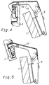
- the wing 1 can first be pivoted by the angle alpha into the dot-dash position 1 ', in which the wing 1, 2 enclose the smallest angle with each other. From the lower part of FIG. 1, the partial wings 1 "and 2" can be seen in their fully open position, in which the partial wings are obtuse to each other.
- the hinges 3 consist of a cross section U-shaped series hinge arm 6, as is used in series production for conventional double-link hinges.
- This series hinge arm is attached to the partial wing 1 via a conventional support plate 7.
- the series hinge arm 6 and the support plate 7 are of conventional design and therefore need not be described in more detail.
- the support plate 7 expediently consists of a base plate and one or more intermediate plates, which are displaceable and / or pivotable relative to one another for the adjustment of the series hinge arm 6 and can be fixed relative to one another in the set positions.
- the series hinge arm 6 has at its front end in its side legs two mutually aligned bores 8, 9, which in the manufacture of conventional double-link hinges kidney for receiving the hinge arm-side hinge pins Articulation part 10 of the hinge arm, so that the series hinge arm 6 can be connected to the articulation part 10 by pins which pass through the aligned bores of the series hinge arm and the articulation part and are riveted into the bores of the series hinge arm.
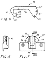
- the articulation part 10 of the hinge arm is angled several times in the manner best seen in FIG. 6 and has an essentially U-shaped shape.
- the straight middle part 11 of the articulation part has a U-shaped profile.
- Angled, forked end parts 12, 13 adjoin the middle part 11, the legs of the forked end part 12 being provided with bores 14, 15 which are aligned with the joint bores 8, 9 of the series hinge arm 6.
- the forked legs of the end part 13 have aligned bores 16, which support the articulation part by a hinge pin 17 in the cup-shaped hinge part 18 serve.
- a cylindrical section 20 made of plastic is held on a bolt 19, which section forms a stop limiting the opening angle.
- the angled, forked ends 13 are mounted in a recess 22 of the hinge cup 18 around the hinge pin 17, the flat walls 23, 24 of the recess 22 forming guides for the angled and forked legs 13.
- the ends of the forked legs are provided with a curve part 26 which is concentric with the bore 16 and to which a curve part 28 is connected via an outwardly directed step 27.
- a pin 30 is guided parallel to the hinge axis 17 and is held in a slightly rolled end of a curved leaf spring 31.
- the other, also slightly rolled end 32 of the leaf spring 31 is held in a slot 33 which is located on the lower edge of a raised platform 34 forming the bottom of the cup-shaped hinge part 18.
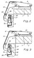
- the representation according to FIG. 2 differs from that according to FIG. 3 in that the partial wings 1 ', 2' have a greater thickness in this.
- a series hinge arm 6 'with an associated support plate 7' is used in the thicker partial wings 1 ', 2' according to FIG. 3, in which the joint bores 8 'and 9' are closer are located on the partial wing 1 'and project further beyond it. From Figures 2 and 3 is thus it can be seen that the hinge according to the invention can be adapted to different thicknesses of partial wings with identical design of the articulation part and the hinge part articulated thereon in that different embodiments of series hinge arms with associated support plates are used.
- the leaf spring 31 itself lies between the forked legs of the end part 13 of the articulation part 10.
Abstract
Description
Die Erfindung betrifft ein Scharnier zur gelenkigen Verbindung zweier Teilflügel eines Türflügels nach dem Oberbegriff des Anspruchs 1.The invention relates to a hinge for the articulated connection of two partial leaves of a door leaf according to the preamble of
Scharniere zur gelenkigen Verbindung zweier Teilflügel eines Türflügels sollen in einfacher Weise an Teilflügel unterschiedlicher Dicke anpaßbar sein. Bei aus DE-U-92 03 048 und EP-A-0 463 439 bekannten Scharnieren wird eine Anpassung an unterschiedlich dicke Teilflügel dadurch erreicht, daß die die Spalte zwischen den Teilflügeln überbrückenden Teile der Scharnierarme geteilt und in einer Trennebene, die senkrecht zu der winkelhalbierenden des von den Teilflügeln eingeschlossenen Winkels verläuft, verschieblich und in den durch Verschiebung eingestellten Stellungen durch eine Klemmschraube miteinander verspannbar sind. Die bekannten Scharniere erfordern nicht nur aufwendige Sonderfertigungen, sie sind auch dadurch in ihrer Stabilität beeinträchtigt, daß die Scharnierarme teilbar sind und durch Befestigungsschrauben miteinander verspannt werden müssen.Hinges for the articulated connection of two wing parts of a door wing should be adaptable to wing parts of different thickness in a simple manner. In the case of hinges known from DE-U-92 03 048 and EP-A-0 463 439, adaptation to partial thicknesses of the wings is achieved in that the parts of the hinge arms bridging the gaps between the partial wings are divided and in a parting plane perpendicular to that bisects the angle enclosed by the partial wings, is displaceable and can be clamped together in the positions set by displacement by means of a clamping screw. The known hinges not only require complex special productions, they are also impaired in their stability in that the hinge arms are divisible and must be clamped together by means of fastening screws.
Aus EP-A-O 468 176 ist ein Scharnier nach dem Oberbegriff des Patentanspruchs 1 bekannt, das mit einem einstückigen abgewinkelten Scharnierarm versehen ist, der besonders angefertigt werden muß, so daß dessen Herstellung wegen der erforderlichen Sonderfertigung verhältnismäßig teuer ist.From EP-A-O 468 176 a hinge according to the preamble of
Aufgabe der Erfindung ist es daher, ein Scharnier der eingangs angegebenen Art zu schaffen, das sich bei verringertem Fertigungsaufwand und guter Stabilität in einfacher Weise an unterschiedlich dicke Teilflügel eines Türflügels anpassen läßt.The object of the invention is therefore to provide a hinge of the type specified, which can be easily adapted to different thicknesses of part of a door wing with reduced manufacturing costs and good stability.
Erfindungsgemäß wird diese Aufgabe durch die kennzeichnenden Merkmale des Patentanspruchs 1 gelöst.According to the invention, this object is achieved by the characterizing Features of
Grundsätzlich stellt jeder Hersteller von Möbelscharnieren Doppellenkerscharniere in Großserien her, bei denen auf Tragplatten befestigbare Scharnierarme über zwei Lenker gelenkig mit topfförmigen Scharnierteilen verbunden sind. Diese Doppellenkerscharniere sind die üblichen Scharniere zur Anlenkung von Möbeltüren und -klappen. Erfindungsgemäß besteht das Scharnier aus einem bei jedem Hersteller von Möbelscharnieren vorhandenen Scharnierarm für Doppellenkerscharniere, mit dem gelenkig das mit dem verschwenkbaren Scharnierteil verbundene Anlenkteil des Scharnierarms fest verbunden ist. Zur Herstellung des erfindungsgemäßen Scharniers ist es somit lediglich erforderlich, den verschwenkbaren Scharnierteil und das mit diesem gelenkig verbundene Anlenkteil in einer Sonderfertigung herzustellen und dann mit dem Serienscharnierarm zu verbinden. Dadurch wird der erforderliche Fertigungsaufwand zur Herstellung des erfindungsgemäßen Scharniers wesentlich verringert, weil ein Teil des Scharnierarms bereits aus der üblichen Serienfertigung von Doppellenkerscharnieren zur Verfügung steht.Basically, every manufacturer of furniture hinges produces double-link hinges in large series, in which hinge arms that can be fastened to support plates are articulated with cup-shaped hinge parts via two links. These double-link hinges are the usual hinges for hinging furniture doors and flaps. According to the invention, the hinge consists of a hinge arm for double-link hinges available at every manufacturer of furniture hinges, with which the articulation part of the hinge arm connected to the pivotable hinge part is articulated. To produce the hinge according to the invention, it is therefore only necessary to produce the pivotable hinge part and the articulated part connected to it in a special production and then to connect it to the series hinge arm. As a result, the manufacturing effort required to produce the hinge according to the invention is significantly reduced because part of the hinge arm is already available from the usual series production of double-link hinges.
Das Anlenkteil des Scharnierarms wird mit dem Serienscharnierarm fest verbunden, so daß sich keine Stabilitätsprobleme aus einer Verstellbarkeit der Scharnierarme ergeben. Eine Anpassung an unterschiedlich dicke Teilflügel wird bei dem erfindungsgemäßen Scharnier dadurch erreicht, daß übliche Sonderformen von Serienscharnierarmen mit zugehörigen Tragplatten verwendet werden. Bei der üblichen Serienherstellung von Doppellenkerscharnieren werden unterschiedliche Scharnierarmformen hergestellt, bei denen die Gelenkbohrungen der Serienscharnierarme unterschiedliche Abstände zu den Korpusteilen aufweisen, an denen diese über ihre Tragplatten befestigt werden. Eine besondere Anpassung der verschwenkbaren Scharnierteile ist nicht erforderlich, da die Anpassung an unterschiedliche Dicken der Teilflügel allein durch die Auswahl der Serienscharnierarme sowie der zugehörigen Tragplatten erfolgt. Das Anlenkteil des erfindungsgemäßen Scharnierarms ist mit dem Scharnierarm durch zwei Stifte verbunden, die die Gelenkbohrungen des Serienscharnierarms und die mit diesen fluchtenden Bohrungen des Anlenkteils durchsetzen. Diese Stifte werden dann in gleicher Weise in den Gelenkbohrungen des Serienscharnierarms vernietet, wie es bei der Herstellung von Doppellenkerscharnieren bei der Lagerung der Lenker auf den Stiften erfolgt.The articulation part of the hinge arm is firmly connected to the series hinge arm, so that there are no stability problems from an adjustability of the hinge arms. An adaptation to different thicknesses of partial wings is achieved in the hinge according to the invention in that customary special shapes of series hinge arms with associated support plates are used. In the usual series production of double-link hinges, different hinge arm shapes are produced, in which the articulated bores of the series hinge arms are at different distances from the body parts to which they are fastened via their support plates. A special adjustment of the pivotable hinge parts is not necessary because the adjustment to different thicknesses of the partial wings is achieved solely by selecting the series hinge arms and the associated support plates. The articulation part of the hinge arm according to the invention is connected to the hinge arm by two pins which penetrate the articulated bores of the series hinge arm and the bores of the articulation part which are aligned therewith. These pins are then riveted in the same way in the articulated bores of the series hinge arm, as is the case in the manufacture of double-link hinges when the handlebars are mounted on the pins.
Der Scharnierarm kann auf üblichen Tragplatten montiert sein, die eine Verstellung des Scharnierarms in mindestens einer Richtung ermöglichen. Durch diese Verstellbarkeit des Scharnierarms auf üblichen Tragplatten kann eine weitere Anpassung und Einstellung der Scharniere erfolgen.The hinge arm can be mounted on conventional support plates, which allow the hinge arm to be adjusted in at least one direction. This adjustability of the hinge arm on conventional support plates allows the hinges to be further adjusted and adjusted.
Zweckmäßigerweise ist das Anlenkteil in einem topfförmigen Scharnierteil gelagert. Weiterhin ist zweckmäßigerweise nur eine Gelenkachse zur Lagerung des Anlenkteils vorgesehen. Das Anlenkteil kann mit einem sich auf einem Teilflügel abstützenden Anschlag aus Kunststoff versehen sein, der den kleinsten Schwenkwinkel zwischen zwei Teilflügeln begrenzt.The articulation part is expediently mounted in a cup-shaped hinge part. Furthermore, only one is expedient Articulated axis provided for mounting the articulated part. The articulation part can be provided with a plastic stop which is supported on a partial wing and which limits the smallest pivoting angle between two partial wings.
Nach einer bevorzugten Ausführungsform der Erfindung ist vorgesehen, daß das Anlenkteil mit einem zur Schwenkachse konzentrischen Kurvenstück und einem an dieses über eine nach außen gerichtete Stufe anschließenden Kurvenstück versehen ist, auf denen ein zur Schwenkachse paralleler, federbelasteter Stift geführt ist, der im winkeligen Schließbereich der Teilflügel derart an der Stufe anliegt, daß die Teilflügel in Richtung auf ihre winkelige Schließstellung gespreizt werden. Zweckmäßigerweise ist der Stift von dem gekrümmten Ende einer Blattfeder gehalten, deren anderes gekrümmtes Ende in einem Schlitz des verschwenkbaren Scharnierteils befestigt ist, wobei der Stift in Langlöchern von Seitenwänden des verschwenkbaren Scharnierteils geführt ist.According to a preferred embodiment of the invention, it is provided that the articulation part is provided with a curve piece concentric with the pivot axis and a curve piece adjoining it via an outwardly directed step, on which a spring-loaded pin parallel to the pivot axis is guided, which in the angular closing area of the Partial wing rests against the step in such a way that the partial wings are spread in the direction of their angular closed position. The pin is expediently held by the curved end of a leaf spring, the other curved end of which is fastened in a slot in the pivotable hinge part, the pin being guided in elongated holes in the side walls of the pivotable hinge part.
Ein Ausführungsbeispiel der Erfindung wird nachstehend anhand der Zeichnung näher erläutert. In dieser zeigt
- Fig. 1
- eine Draufsicht auf zwei gelenkig durch Scharniere miteinander verbundene Teilflügel, von denen ein Teilflügel durch ein Weitwinkelscharnier an eine Tragwand eines Möbels angelenkt ist,
- Fig. 2
- ein zwei Teilflügel miteinander verbindendes Scharnier, teilweise im Schnitt und in einer Stellung, in der sich die Teilflügel in ihrer rechtwinkelig zueinander stehenden Schließstellung befinden,
- Fig. 3
- eine der Fig. 2 entsprechende Darstellung, bei der jedoch die Teilflügel gegenüber den Teilflügeln nach Fig. 2 eine größere Dicke aufweisen,
- Fig. 4
- eine der Fig. 2 entsprechende Darstellung, bei der die Teilflügel den kleinstmöglichen Winkel miteinander einschließen,
- Fig. 5
- eine der Fig. 2 entsprechende Darstellung, bei der die Teilflügel sich in ihrer geöffneten Stellung befinden und den größtmöglichen Winkel zueinander einnehmen,
- Fig. 6
- eine Seitenansicht des Anlenkteils des Scharnierarms,
- Fig. 7
- eine Draufsicht auf den Scharniertopf und
- Fig. 8
- einen Schnitt durch den Scharniertopf längs der Linie VIII-VIII in Fig. 7.
- Fig. 1
- 2 shows a plan view of two partial wings which are articulated to one another by hinges, of which one partial wing is articulated by a wide-angle hinge to a supporting wall of a piece of furniture,
- Fig. 2
- a hinge connecting two partial wings, partly in section and in a position in which the partial wings are in their closed position at right angles to one another,
- Fig. 3
- a representation corresponding to FIG. 2, in which however, the partial wings have a greater thickness than the partial wings according to FIG. 2,
- Fig. 4
- 2 shows a representation corresponding to that in which the partial wings enclose the smallest possible angle with one another,
- Fig. 5
- 2 shows a representation corresponding to FIG. 2, in which the partial wings are in their open position and are at the largest possible angle to one another,
- Fig. 6
- a side view of the articulation part of the hinge arm,
- Fig. 7
- a top view of the hinge cup and
- Fig. 8
- a section through the hinge cup along the line VIII-VIII in Fig. 7th
Aus Fig. 1 ist eine Draufsicht auf einen Eckschrank ersichtlich, bei dem sich die Teilflügel 1, 2 des Türflügels in ihrer rechtwinkeligen Schließstellung befinden. Dabei sind die Teilflügel 1, 2 durch mindestens zwei erfindungsgemäße Scharniere 3 miteinander verbunden, wobei der innere Teilflügel 2 durch übliche Weitwinkelscharniere 4 mit einer Tragwand 5 des Schranks verbunden ist. Zum Öffnen des Eckschranks läßt sich zunächst der Teilflügel 1 um den Winkel alpha in die strichpunktierte Stellung 1' verschwenken, in der die Teilflügel 1, 2 den kleinsten Winkel miteinander einschließen. Aus dem unteren Teil der Fig. 1 sind die Teilflügel 1" und 2" in ihrer vollständig geöffneten Stellung ersichtlich, in der die Teilflügel stumpfwinkelig zueinander stehen.1 shows a plan view of a corner cabinet in which the
Die erfindungsgemäßen Scharniere 3 bestehen aus einem im Querschnitt U-förmigen Serienscharnierarm 6, wie er bei der Serienherstellung für übliche Doppellenkerscharniere verwendet wird. Dieser Serienscharnierarm ist über eine übliche Tragplatte 7 an dem Teilflügel 1 befestigt. Der Serienscharnierarm 6 sowie die Tragplatte 7 ist üblicher Bauart und braucht daher nicht näher beschrieben zu werden. Die Tragplatte 7 besteht zweckmäßigerweise aus einer Grundplatte und einer oder mehreren Zwischenplatten, die zur Verstellung des Serienscharnierarms 6 relativ zueinander verschieblich und/oder verschwenkbar und in den eingestellten Stellungen relativ zueinander fixierbar sind.The
Der Serienscharnierarm 6 weist an seinem vorderen Ende in seinen Seitenschenkeln jeweils zwei miteinander fluchtende Bohrungen 8, 9 auf, die bei der Herstellung von üblichen Doppellenkerscharnieren nieren der Aufnahme der scharnierarmseitigen Gelenkbolzen Bei dem dargestellten Ausführungsbeispiel des erfindungsgemäßen Scharniers fluchten die Bohrungen 8, 9 mit Bohrungen des Anlenkteils 10 des Scharnierarms, so daß der Serienscharnierarm 6 mit dem Anlenkteil 10 durch Stifte verbunden werden kann, die die fluchtenden Bohrungen des Serienscharnierarms und des Anlenkteils durchsetzen und in den Bohrungen des Serienscharnierarms vernietet sind.The
Das Anlenkteil 10 des Scharnierarms ist in der am besten aus Fig. 6 ersichtlichen Weise mehrfach abgewinkelt und weist eine im wesentlichen U-förmige Form auf. Der gerade Mittelteil 11 des Anlenkteils weist ein U-förmiges Profil auf. An das Mittelteil 11 schließen abgewinkelte, gegabelte Endteile 12, 13 an, wobei die Schenkel des gegabelten Endteils 12 mit Bohrungen 14, 15 versehen sind, die mit den Gelenkbohrungen 8, 9 des Serienscharnierarms 6 fluchten. Die gegabelten Schenkel des Endteils 13 weisen fluchtende Bohrungen 16 auf, die der Lagerung des Anlenkteils durch einen Gelenkstift 17 in dem topfförmigen Scharnierteil 18 dienen. Zwischen den Schenkeln des geraden Mittelteils 11 des Anlenkteils 10 ist auf einem Bolzen 19 ein zylindrischer Abschnitt 20 aus Kunststoff gehaltert, der einen den Öffnungswinkel begrenzenden Anschlag bildet.The
Die abgewinkelten, gegabelten Enden 13 sind in einer Aussparung 22 des Scharniertopfs 18 um den Gelenkbolzen 17 gelagert, wobei die ebenen Wandungen 23, 24 der Aussparung 22 Führungen für die abgewinkelten und gegabelten Schenkel 13 bilden.The angled, forked ends 13 are mounted in a
Die Enden der gegabelten Schenkel sind mit einem zur Bohrung 16 konzentrischen Kurventeil 26 versehen, an den über eine nach außen gerichtete Stufe 27 ein Kurventeil 28 anschließt. Auf der Kurve 26, 27, 28 ist ein zu der Gelenkachse 17 paralleler Stift 30 geführt, der in einem leicht eingerollten Ende einer gebogenen Blattfeder 31 gehaltert ist. Das andere, ebenfalls leicht eingerollte Ende 32 der Blattfeder 31 ist in einem Schlitz 33 gehaltert, der sich am unteren Rand eines den Boden des topfförmigen Scharnierteils 18 bildenden, erhöhten Podests 34 befindet. Zur Montage des Stifts 30 und der Blattfeder 31 ist es lediglich erforderlich, den in die Blattfeder eingelegten Stift 30 gegen die beiden Führungskanten der Kurven 26, 27, 28 zu halten und den anderen Schenkel der Blattfeder 31 derart niederzudrücken, daß das andere Ende 32 in den Halteschlitz 33 einrastet.The ends of the forked legs are provided with a
Die Darstellung gemäß Fig. 2 unterscheidet sich von der gemäß Fig. 3 dadurch, daß in dieser die Teilflügel 1', 2', eine größere Dicke aufweisen. Um bei identischen Abmessungen des Anlenkteils 10 des Scharnierarms eine Montage zu ermöglichen, wird bei den dickeren Teilflügeln 1', 2' gemäß Fig. 3 ein Serienscharnierarm 6' mit zugehöriger Tragplatte 7' verwendet, bei dem sich die Gelenkbohrungen 8' und 9' näher an dem Teilflügel 1' befinden und weiter über diesen hinauskragen. Aus den Figuren 2 und 3 ist somit ersichtlich, daß sich das erfindungsgemäße Scharnier bei identischer Ausgestaltung des Anlenkteils und des an diesen angelenkten Scharnierteils dadurch an unterschiedliche Dicken von Teilflügeln anpassen läßt, daß unterschiedliche Ausführungsformen von Serienscharnierarmen mit zugehörigen Tragplatten verwendet werden.The representation according to FIG. 2 differs from that according to FIG. 3 in that the partial wings 1 ', 2' have a greater thickness in this. In order to enable assembly with identical dimensions of the
Wie aus Fig. 2 ersichtlich ist, liegt in der Schließstellung der von der Blattfeder 31 belastete Stift 30 an der Stufe 27 in der Kurve an, so daß die Teilflügel 1, 2 in Richtung auf ihre rechtwinkelige Schließstellung vorgespannt sind. Der Stift 30 ist in Langlöchern 40 des topfförmigen Scharnierteils 18 geführt, so daß er die erforderliche Ausgleichsbewegung bei seinem Gleiten über die Stufe 27 ausführen kann.As can be seen from FIG. 2, in the closed position the
Die Blattfeder 31 selbst liegt zwischen den gegabelten Schenkeln des Endteils 13 des Anlenkteils 10.The
Claims (7)
- Hinge (3) for the articulated junction of two wings (1, 2) of a folding door which, in their closed position, assume an angled position in respect of one another, and of which one wing (2) is attached to a body component (5) of an item of furniture or similar,consisting of an angled hinge arm (6, 10) which may be fixed to one wing (1) and which is fixed on a mounting plate (7, 7'), andof a second hinge element (18) which can be fixed to the other wing (2), to which hinge element (18) the free end of the hinge arm (6, 10) is pivot mounted,with the angled hinge arm (6, 10) being angled in the slewing plane of the hinge (3) so that the link pin (17) connecting said angled hinge arm (6, 10) to the hinge element (18), which may be fixed to the other wing (2), runs transverse to said hinge arm (6,10),characterised in thatthe angled hinge arm (6, 10) consists of a straight section (6) which may be fixed to the mounting plate (7, 7'), and of an angled articulation section (10),the straight section (6) of the hinge arm (6, 10) corresponds to a double link hinge, andthe articulated section (10) is connected to the straight section (6, 6') by two pins which pass through the link holes (8, 9) of the straight section (6, 6') and holes (14, 15) flush-aligned to these of the articulated section (10).
- Hinge according to Claim 1, characterised in that the hinge arm (6) is fitted to a mounting plate (7) which facilitates the adjustment of the hinge arm in at least one direction.
- Hinge according to Claim 1 or 2, characterised in that the articulated section (10) is mounted in a cup-shaped hinge element.
- Hinge according to one of Claims 1 to 3, characterised in that the articulated section (10) is pivot mounted on a single axis of articulation (17).
- Hinge according to one of Claims 1 to 4, characterised in that the articulated section (10) is provided with a plastic stop attachment (20) which rests on one wing.
- Hinge according to one of Claims 1 to 5, characterised in that the articulated section (10) is provided with a curved element (26) which is concentric to the pivot axis (17), and a further curve element (28) adjoining this via an outwardly directed step (27), on which curved sections (26, 28) is guided a spring-loaded pin (30) arranged parallel to the pivot axis (17), which in the angled closing range of the wings (1, 2) rests against the step (27) such that the wings (1, 2) are spread in the direction of their angled closed position.
- Hinge according to Claim 6, characterised in that the pin (30) is retained by the curved end of a bent leaf spring (31), the other curved end (32) of which is fixed in a slot (33) of the slewing hinge element (18), and is guided in oblong holes (40) in the side walls of the slewing hinge element (18).
Applications Claiming Priority (2)
| Application Number | Priority Date | Filing Date | Title |
|---|---|---|---|
| DE4310626A DE4310626C1 (en) | 1993-03-31 | 1993-03-31 | Hinge between furniture-door leaves |
| DE4310626 | 1993-03-31 |
Publications (2)
| Publication Number | Publication Date |
|---|---|
| EP0620346A1 EP0620346A1 (en) | 1994-10-19 |
| EP0620346B1 true EP0620346B1 (en) | 1997-04-09 |
Family
ID=6484420
Family Applications (1)
| Application Number | Title | Priority Date | Filing Date |
|---|---|---|---|
| EP94101314A Expired - Lifetime EP0620346B1 (en) | 1993-03-31 | 1994-01-28 | Hinge for the articulated junction of two wings of a folding door |
Country Status (6)
| Country | Link |
|---|---|
| US (1) | US5765262A (en) |
| EP (1) | EP0620346B1 (en) |
| JP (1) | JP2635004B2 (en) |
| AT (1) | ATE151493T1 (en) |
| DE (2) | DE4310626C1 (en) |
| ES (1) | ES2099496T3 (en) |
Families Citing this family (12)
| Publication number | Priority date | Publication date | Assignee | Title |
|---|---|---|---|---|
| EP0861961B1 (en) * | 1997-02-28 | 2004-05-19 | Formenti & Giovenzana S.p.A. | Snap-action hinge for furniture doors |
| DE29709806U1 (en) * | 1997-04-30 | 1997-07-31 | Salice Arturo Spa | Wide angle hinge |
| AT413418B (en) * | 2004-02-09 | 2006-02-15 | Blum Gmbh Julius | CABINET FURNITURE |
| DE102005037749A1 (en) * | 2005-08-10 | 2007-02-15 | Sms Demag Ag | Cooling device of individual segments for electrodes of a metallurgical furnace |
| AU2012302795A1 (en) * | 2011-08-31 | 2014-04-17 | Sugatsune Kogyo Co., Ltd. | Rotary damper and hinge device with damper |
| US9918547B2 (en) * | 2016-03-08 | 2018-03-20 | True Manufacturing Co., Inc. | Refrigerated food preparation table and hinge bracket for holding lid partially or fully open |
| DE202016006656U1 (en) * | 2016-10-28 | 2018-02-01 | Hetal-Werke Franz Hettich Gmbh & Co. Kg | Control device for controlling the movement of a corner cabinet door of a corner cabinet |
| DE202016006655U1 (en) | 2016-10-28 | 2018-02-01 | Hetal-Werke Franz Hettich Gmbh & Co. Kg | Corner |
| CN109779427A (en) * | 2019-03-23 | 2019-05-21 | 广东星徽精密制造股份有限公司 | A kind of transmission device of Turning over door hange |
| CN109972951B (en) * | 2019-03-23 | 2023-09-15 | 广东星徽精密制造股份有限公司 | Automatic turn-up door buffering hinge of opening and close |
| WO2020220156A1 (en) * | 2019-04-28 | 2020-11-05 | 佛山市爱迪尔卫浴有限公司 | Hinge and shower door assembly |
| WO2021029697A1 (en) * | 2019-08-13 | 2021-02-18 | 엘지전자 주식회사 | Clothes treatment apparatus |
Family Cites Families (14)
| Publication number | Priority date | Publication date | Assignee | Title |
|---|---|---|---|---|
| FR2258508B1 (en) * | 1974-01-17 | 1978-03-31 | Paumellerie Electrique | |
| US4157599A (en) * | 1977-12-19 | 1979-06-12 | Jaybee Manufacturing Corporation | Wide-angled self contained hinge for panel door cabinet |
| JPS5834215U (en) * | 1981-08-28 | 1983-03-05 | 和光電気株式会社 | lighting equipment |
| JPS59100073U (en) * | 1982-12-24 | 1984-07-06 | 株式会社三渡工業所 | hinge |
| DE8616321U1 (en) * | 1986-06-18 | 1987-11-12 | Praemeta Praezisionsmetall- Und Kunststofferzeugnisse G. Baumann & Co, 5000 Koeln, De | |
| DE8710717U1 (en) * | 1987-08-05 | 1988-12-01 | Praemeta Praezisionsmetall- Und Kunststofferzeugnisse G. Baumann & Co, 5000 Koeln, De | |
| DE3820338A1 (en) * | 1988-06-15 | 1989-12-21 | Lautenschlaeger Kg Karl | FURNITURE HINGE |
| US4873743A (en) * | 1988-12-29 | 1989-10-17 | Kabushiki Kaisha Murakoshi Seiko | Hinge |
| DE4016664C2 (en) * | 1990-04-27 | 1993-11-11 | Salice Arturo Spa | hinge |
| AT397407B (en) * | 1990-06-25 | 1994-04-25 | Blum Gmbh Julius | HINGE |
| US5201096A (en) * | 1990-06-25 | 1993-04-13 | Julius Blum Gesellschaft M.B.H. | Hinge |
| DE4023790A1 (en) * | 1990-07-26 | 1992-02-06 | Salice Arturo Spa | HINGE FOR THE ARTICULATED CONNECTION OF TWO PART WINGS OF A DOOR WING |
| DE4133343C1 (en) * | 1991-10-08 | 1993-02-25 | Arturo Salice S.P.A., Novedrate, Como, It | Door hinge for furniture - has arm end with joint connection bent or angled to bring hinge arm in parallel to arm long axis |
| DE9203048U1 (en) * | 1992-03-07 | 1992-04-23 | Paul Hettich Gmbh & Co, 4983 Kirchlengern, De |
-
1993
- 1993-03-31 DE DE4310626A patent/DE4310626C1/en not_active Expired - Fee Related
-
1994
- 1994-01-28 DE DE59402335T patent/DE59402335D1/en not_active Expired - Lifetime
- 1994-01-28 EP EP94101314A patent/EP0620346B1/en not_active Expired - Lifetime
- 1994-01-28 AT AT94101314T patent/ATE151493T1/en active
- 1994-01-28 ES ES94101314T patent/ES2099496T3/en not_active Expired - Lifetime
- 1994-03-31 JP JP6062857A patent/JP2635004B2/en not_active Expired - Fee Related
-
1996
- 1996-11-08 US US08/745,225 patent/US5765262A/en not_active Expired - Lifetime
Also Published As
| Publication number | Publication date |
|---|---|
| JPH07119348A (en) | 1995-05-09 |
| ES2099496T3 (en) | 1997-05-16 |
| US5765262A (en) | 1998-06-16 |
| DE4310626C1 (en) | 1994-06-23 |
| JP2635004B2 (en) | 1997-07-30 |
| ATE151493T1 (en) | 1997-04-15 |
| DE59402335D1 (en) | 1997-05-15 |
| EP0620346A1 (en) | 1994-10-19 |
Similar Documents
| Publication | Publication Date | Title |
|---|---|---|
| EP1574649B1 (en) | Door hinge for hidden assembly between door frame and door wing | |
| DE3218375A1 (en) | UNIVERSAL FURNITURE HINGE | |
| EP0620346B1 (en) | Hinge for the articulated junction of two wings of a folding door | |
| AT401667B (en) | FURNITURE HINGE WITH LOCKING MECHANISM | |
| DE4241690C1 (en) | Furniture hinge | |
| DE4035199C2 (en) | Single hinge furniture hinge | |
| AT401666B (en) | FURNITURE HINGE WITH LOCKING MECHANISM | |
| EP0789125B1 (en) | Supporting member for a closure element, preferably for a wing of a sliding and folding door | |
| EP0099042B1 (en) | Furniture door hinge with a closure mechanism | |
| EP2130997A2 (en) | Hinge | |
| DE102008028633A1 (en) | Drive arrangement for a swing wing | |
| EP0595045A1 (en) | Hinge, especially furniture hinge | |
| EP3737816B1 (en) | Furniture hinge, furniture panel, and furniture body | |
| EP0237789B1 (en) | Door hinge allowing a 180 degrees opening | |
| DE3307777C2 (en) | Concealed hinge with locking device | |
| DE3943330C1 (en) | ||
| EP0625237B1 (en) | Corner-cupboard hinge | |
| AT409880B (en) | UNIVERSAL JOINT HINGE | |
| EP0463439B1 (en) | Hinge | |
| DE4023790A1 (en) | HINGE FOR THE ARTICULATED CONNECTION OF TWO PART WINGS OF A DOOR WING | |
| AT503457B1 (en) | HINGE FOR SWIVELING FLAP OR DOOR WINGS IN THE BASKET OF FURNITURE PIECES | |
| DE7715244U1 (en) | FURNITURE HINGE | |
| EP0875648B1 (en) | Wide-angle hinge | |
| EP0221253A1 (en) | Furniture door hinge with a closure mechanism | |
| DE10015805A1 (en) | Adjustable base for furniture hinge having tilting arm comprises base element with oscillating intermediate element and side wings with arms extending from side walls laterally projecting pivot section |
Legal Events
| Date | Code | Title | Description |
|---|---|---|---|
| PUAI | Public reference made under article 153(3) epc to a published international application that has entered the european phase |
Free format text: ORIGINAL CODE: 0009012 |
|
| AK | Designated contracting states |
Kind code of ref document: A1 Designated state(s): AT DE ES IT |
|
| 17P | Request for examination filed |
Effective date: 19941122 |
|
| 17Q | First examination report despatched |
Effective date: 19951222 |
|
| GRAG | Despatch of communication of intention to grant |
Free format text: ORIGINAL CODE: EPIDOS AGRA |
|
| GRAH | Despatch of communication of intention to grant a patent |
Free format text: ORIGINAL CODE: EPIDOS IGRA |
|
| GRAH | Despatch of communication of intention to grant a patent |
Free format text: ORIGINAL CODE: EPIDOS IGRA |
|
| GRAA | (expected) grant |
Free format text: ORIGINAL CODE: 0009210 |
|
| AK | Designated contracting states |
Kind code of ref document: B1 Designated state(s): AT DE ES IT |
|
| REF | Corresponds to: |
Ref document number: 151493 Country of ref document: AT Date of ref document: 19970415 Kind code of ref document: T |
|
| REF | Corresponds to: |
Ref document number: 59402335 Country of ref document: DE Date of ref document: 19970515 |
|
| REG | Reference to a national code |
Ref country code: ES Ref legal event code: FG2A Ref document number: 2099496 Country of ref document: ES Kind code of ref document: T3 |
|
| PLBE | No opposition filed within time limit |
Free format text: ORIGINAL CODE: 0009261 |
|
| STAA | Information on the status of an ep patent application or granted ep patent |
Free format text: STATUS: NO OPPOSITION FILED WITHIN TIME LIMIT |
|
| 26N | No opposition filed | ||
| PGFP | Annual fee paid to national office [announced via postgrant information from national office to epo] |
Ref country code: AT Payment date: 20110121 Year of fee payment: 18 Ref country code: DE Payment date: 20110127 Year of fee payment: 18 Ref country code: IT Payment date: 20110119 Year of fee payment: 18 |
|
| PGFP | Annual fee paid to national office [announced via postgrant information from national office to epo] |
Ref country code: ES Payment date: 20110119 Year of fee payment: 18 |
|
| PG25 | Lapsed in a contracting state [announced via postgrant information from national office to epo] |
Ref country code: DE Free format text: LAPSE BECAUSE OF NON-PAYMENT OF DUE FEES Effective date: 20120801 |
|
| REG | Reference to a national code |
Ref country code: DE Ref legal event code: R119 Ref document number: 59402335 Country of ref document: DE Effective date: 20120801 |
|
| PG25 | Lapsed in a contracting state [announced via postgrant information from national office to epo] |
Ref country code: IT Free format text: LAPSE BECAUSE OF NON-PAYMENT OF DUE FEES Effective date: 20120128 |
|
| REG | Reference to a national code |
Ref country code: AT Ref legal event code: MM01 Ref document number: 151493 Country of ref document: AT Kind code of ref document: T Effective date: 20120128 |
|
| PG25 | Lapsed in a contracting state [announced via postgrant information from national office to epo] |
Ref country code: AT Free format text: LAPSE BECAUSE OF NON-PAYMENT OF DUE FEES Effective date: 20120128 |
|
| REG | Reference to a national code |
Ref country code: ES Ref legal event code: FD2A Effective date: 20130708 |
|
| PG25 | Lapsed in a contracting state [announced via postgrant information from national office to epo] |
Ref country code: ES Free format text: LAPSE BECAUSE OF NON-PAYMENT OF DUE FEES Effective date: 20120129 |