EP1308343A2 - Fahrzeugsitz, insbesondere Kraftfahrzeugrücksitz - Google Patents
Fahrzeugsitz, insbesondere Kraftfahrzeugrücksitz Download PDFInfo
- Publication number
- EP1308343A2 EP1308343A2 EP02022740A EP02022740A EP1308343A2 EP 1308343 A2 EP1308343 A2 EP 1308343A2 EP 02022740 A EP02022740 A EP 02022740A EP 02022740 A EP02022740 A EP 02022740A EP 1308343 A2 EP1308343 A2 EP 1308343A2
- Authority
- EP
- European Patent Office
- Prior art keywords
- locking
- vehicle
- locking rail
- adapter arrangement
- seat
- Prior art date
- Legal status (The legal status is an assumption and is not a legal conclusion. Google has not performed a legal analysis and makes no representation as to the accuracy of the status listed.)
- Withdrawn
Links
Images


Classifications
-
- B—PERFORMING OPERATIONS; TRANSPORTING
- B60—VEHICLES IN GENERAL
- B60N—SEATS SPECIALLY ADAPTED FOR VEHICLES; VEHICLE PASSENGER ACCOMMODATION NOT OTHERWISE PROVIDED FOR
- B60N2/00—Seats specially adapted for vehicles; Arrangement or mounting of seats in vehicles
- B60N2/02—Seats specially adapted for vehicles; Arrangement or mounting of seats in vehicles the seat or part thereof being movable, e.g. adjustable
- B60N2/04—Seats specially adapted for vehicles; Arrangement or mounting of seats in vehicles the seat or part thereof being movable, e.g. adjustable the whole seat being movable
- B60N2/06—Seats specially adapted for vehicles; Arrangement or mounting of seats in vehicles the seat or part thereof being movable, e.g. adjustable the whole seat being movable slidable
- B60N2/07—Slide construction
- B60N2/0702—Slide construction characterised by its cross-section
- B60N2/0715—C or U-shaped
-
- B—PERFORMING OPERATIONS; TRANSPORTING
- B60—VEHICLES IN GENERAL
- B60N—SEATS SPECIALLY ADAPTED FOR VEHICLES; VEHICLE PASSENGER ACCOMMODATION NOT OTHERWISE PROVIDED FOR
- B60N2/00—Seats specially adapted for vehicles; Arrangement or mounting of seats in vehicles
- B60N2/02—Seats specially adapted for vehicles; Arrangement or mounting of seats in vehicles the seat or part thereof being movable, e.g. adjustable
- B60N2/04—Seats specially adapted for vehicles; Arrangement or mounting of seats in vehicles the seat or part thereof being movable, e.g. adjustable the whole seat being movable
- B60N2/06—Seats specially adapted for vehicles; Arrangement or mounting of seats in vehicles the seat or part thereof being movable, e.g. adjustable the whole seat being movable slidable
- B60N2/08—Seats specially adapted for vehicles; Arrangement or mounting of seats in vehicles the seat or part thereof being movable, e.g. adjustable the whole seat being movable slidable characterised by the locking device
- B60N2/0812—Location of the latch
- B60N2/0825—Location of the latch outside the rail
-
- B—PERFORMING OPERATIONS; TRANSPORTING
- B60—VEHICLES IN GENERAL
- B60N—SEATS SPECIALLY ADAPTED FOR VEHICLES; VEHICLE PASSENGER ACCOMMODATION NOT OTHERWISE PROVIDED FOR
- B60N2/00—Seats specially adapted for vehicles; Arrangement or mounting of seats in vehicles
- B60N2/02—Seats specially adapted for vehicles; Arrangement or mounting of seats in vehicles the seat or part thereof being movable, e.g. adjustable
- B60N2/04—Seats specially adapted for vehicles; Arrangement or mounting of seats in vehicles the seat or part thereof being movable, e.g. adjustable the whole seat being movable
- B60N2/06—Seats specially adapted for vehicles; Arrangement or mounting of seats in vehicles the seat or part thereof being movable, e.g. adjustable the whole seat being movable slidable
- B60N2/08—Seats specially adapted for vehicles; Arrangement or mounting of seats in vehicles the seat or part thereof being movable, e.g. adjustable the whole seat being movable slidable characterised by the locking device
- B60N2/0831—Movement of the latch
- B60N2/0837—Movement of the latch pivoting
- B60N2/085—Movement of the latch pivoting about a transversal axis
Definitions
- the invention relates to a vehicle seat, in particular a motor vehicle rear seat, with the features of the preamble of claim 1.
- a vehicle seat of this type is known in which the locking rail is covered with a cover for locking catches which the locking element normally during a longitudinal adjustment rolls.
- the adapter arrangement performs a defined rotation, see above that the locking element pushes through the shell and from the closest Detent is recorded. The manufacturing cost of such a locking rail and assembly effort when adjusting the adapter arrangement still leave Wishes open.
- the invention is based on the object of a vehicle seat of the type mentioned Kind of improve. This object is achieved by a vehicle seat solved with the features of claim 1.
- Advantageous configurations are the subject of the subclaims.
- the adapter arrangement and / or its connection is deformable in the event of a crash and / or can be partially destroyed in a targeted manner and that by the defined deformation or partial destruction of the locking element relative to the locking rail moves, the effort involved in adjusting the adapter arrangement is reduced, because higher tolerances for the distance are possible.
- the locking rail no longer has to be covered with a cover.
- the deformation of the Connection can take place, for example, in rigid rockers or holding tubes, while the destruction is preferably limited to a shear pin.
- the locking rail can be moved from the Vehicle structure to be detachable, for example by opening a locking device.
- the locking rail can also be in the package position with the vehicle structure be connected by, for example, the adapter arrangement a locking device has, which is for the transition to the package position of the locking element solves to with the connection and the element of the seat belt system perform a pivotal movement, or by the adapter assembly is arranged above the locking rail at a distance from it and for the transition to the package position with the connection and the element of the seat belt system performs a pivoting movement.
- an additional fuse is provided, which the locking rail is normally firmly connected to the vehicle structure holds and in the event of a crash when a load level is exceeded a degree of freedom of Locking rail releases, so that this, for example, articulated with the vehicle structure is connected and can perform a compensatory movement.
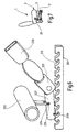
- a vehicle seat 1 is a middle seat in one Rear seat system of a motor vehicle provided, its orientation and ordinary Direction of travel defines the directional information used.
- the structure the seat part 3 of the vehicle seat 1, hereinafter referred to as the seat part structure 5, has a longitudinal adjuster consisting of two pairs of rails in the lower area 7 as a device for adjusting the longitudinal position of the vehicle seat 1.
- the seat part 3 can be pivoted upwards into an upright position.
- a U-shaped locking rail open to the left and right 11 attached, which point symmetrically downward at both of them Flanks in the longitudinal direction one behind the other several crescent-shaped, downwards has open catches 12.
- a locking device 13 articulated, which is detachable with a fastening bolt B the vehicle structure is locked.
- the front joint 15 is through a shear pin 21 locked so that the locking rail 11 is immobile connected to the vehicle structure or - after unlocking the locking device 13 - together with the seat part 3 can be swiveled upwards into the package position is.
- a cross tube 23 of the seat structure 5 are laterally the locking rail 11 two deformation wings 25 welded, which protrude obliquely downwards.
- a locking unit arranged between the deformation rockers 25 27 encloses the locking rail 11 with an almost ring-shaped closed Profile and is usually on the top of the locking rail 11 on.
- a horizontally arranged between the two swing arms 25 Locking bolt 29 connects the locking unit 27 to the deformation rockers 25. In the normal case, the locking bolt 29 is below the locking rail 11 arranged at a distance from the notches 12.
- the deformation rockers 25 and the locking unit 27 form an adapter arrangement.
- On the locking unit 27 is on both sides of the locking rail 11 each a link 31 articulated.
- one of the two locking rails 11 is on one of these tabs 31 as part of a seat belt system a buckle 33 attached while the other locking rail 11 the lower end of a seat belt is attached to one of these tabs 31.
- the longitudinal position of the vehicle seat 1 is adjusted by means of the longitudinal adjuster 7 moves the locking unit 27 together with the buckle 33 on the locking rail 11 along.
- the deformation wings can 25 a horizontal, firmly engage with the locking device 13, engage around the retaining bolt 35.
- the retaining bolt 35 also serves to link the locking device 13 to the locking rail 11th
- the crash forces introduced via the belt buckle 33 predominantly deform the cross tube 23 and possibly the deformation rockers 25.
- Die Locking unit 27 is raised and the locking bolt 29 enters Engagement with two opposite latches 12 of the locking rail 11.
- the crash forces are direct, i.e. under bridging - and with it Relief - of the longitudinal adjuster 7 and the areas attached above it the seat part structure 5, into the locking rail 11 and further into the vehicle structure initiated.
- the shear pins shear 21 from, i.e. the front joint 15 is released in each case.
- the locking device 13, the locking rail 11, the front rocker 17 and the vehicle structure between the hinge device 19 and the fastening bolt B on each side form four joints, which are now in accordance with the inertia in the present Align crash case, each of the locking rail 11 in their Moves in the longitudinal direction and the front rocker 17 performs a pivoting movement. Due to the principle of the four-bar system, there are no additional bending moments initiated by the attachment to the vehicle structure in the locking rail 11.
- An upwardly open locking rail 111 is fixed to the vehicle structure connected, with detents 112 being provided within lateral backdrops 111 ' are.
- a locking device 113 is in a sliding element 114 with a horizontal arranged locking bolt 129, wherein the sliding member 114th is slidably guided within the locking rail 111.
- the length of the Locking bolt 129 is dimensioned so that it projects into the scenes 111 'and is arranged below the notches 112 at a distance from the same.
- the locking device 113 is attached to a cross tube 123 and carries as part of an adapter arrangement at its upper end articulated a tab 131 on which, for example the buckle 133 is attached.
- the closing device 113 slides with the sliding element 114 at one Longitudinal adjustment of the vehicle seat in the locking rail 111 along or detaches from the locking bolt 129 during the transition to the package position.
- the transverse tube 123 is deformed by the crash forces and the Locking device 113 pulled up by the buckle 133.
- the Locking device 113 pulls the sliding element 114 upward, so that the locking bolt 129 engages with a pair of opposed notches 112.
- the crash forces are now directly - bypassing the longitudinal adjuster, i.e. without straining the seat structure - introduced into the vehicle structure.
- An upwardly open locking rail 211 is fixed to the vehicle structure connected and carries upwards, at an angle of 45 ° backwards open catches 212.
- a flat tube is attached to a cross tube 223 by means of a joint 224
- Lever 227 attached, the hinge 224 normally by a shear pin 221 is held rigid.
- the lever 227 carries one at its rear end horizontally arranged locking bolt 229.
- At the front end of the as A lever 231 is hinged to the adapter arrangement provided lever 227, on which for example, the belt buckle 233 is attached.
- the lever 227 slides when the vehicle seat is adjusted lengthways above the locking rail 211 along or detaches from the same at Transition to the package position.
- the lever 227 can now about the hinge 224 swing.
- the buckle 233 pulls the lever 227 at its front end up so that the locking pin 229 is pressed into a pair of notches 212 which lie opposite one another transversely to the longitudinal direction of the locking rail 211.
- the belt force directed obliquely upwards acts approximately perpendicular to Longitudinal direction of the notches 212, i.e. the locking bolt 229 can engage Don't leave 212 again.
- the crash forces are now direct - with bridging of the longitudinal adjuster - introduced into the vehicle structure.
Landscapes
- Engineering & Computer Science (AREA)
- Aviation & Aerospace Engineering (AREA)
- Transportation (AREA)
- Mechanical Engineering (AREA)
- Seats For Vehicles (AREA)
Abstract
Description
- Fig. 1
- eine perspektivische Teilansicht des ersten Ausführungsbeispiels,
- Fig. 2
- eine perspektivische Ansicht einer Deformationsschwinge,
- Fig. 3
- eine perspektivische Ansicht einer Verriegelungseinheit,
- Fig. 4
- eine perspektivische Teilansicht des zweiten Ausführungsbeispiels,
- Fig. 5
- eine Teilansicht der Stirnseite des zweiten Ausführungsbeispiels,
- Fig. 6
- eine perspektivische Teilansicht des dritten Ausführungsbeispiels, und
- Fig. 7
- eine schematische Seitenansicht des ersten Ausführungsbeispiels.
- 1
- Fahrzeugsitz
- 3
- Sitzteil
- 5
- Sitzteilstruktur
- 7
- Längseinsteller
- 11, 111, 211
- Verriegelungsschiene
- 12, 112, 212
- Raste
- 13, 113
- Schließeinrichtung
- 15
- vorderes Gelenk
- 17
- vordere Schwinge
- 19
- Gelenkvorrichtung
- 21,221
- Abscherstift
- 23, 123, 223
- Querrohr
- 25
- Deformationsschwinge
- 27
- Verriegelungseinheit
- 29, 129, 229
- Verriegelungsbolzen
- 31,131,231
- Lasche
- 33, 133, 233
- Gurtschloß
- 35
- Haltebolzen
- 111'
- Kulisse
- 114
- Gleitelement
- 224
- Gelenk
- 227
- Hebel
- B
- Befestigungsbolzen
Claims (9)
- Fahrzeugsitz, insbesondere Kraftfahrzeugrücksitz, mit einer Sitzteilstruktur (5), welche einen Längseinsteller (7), eine wenigstens in einer Gebrauchsstellung mit der Fahrzeugstruktur verbundene Verriegelungsschiene (11; 111; 211), eine Adapteranordnung (27; 113, 114; 227) zur Anbringung von Elementen (33; 133; 233) eines Sicherheitsgurtsystems und eine Anbindung (23, 25; 123; 223) der Adapteranordnung (27; 113, 114; 227) innerhalb der Sitzteilstruktur (5) aufweist, wobei die Adapteranordnung (27; 113, 114; 227) mit einem Verriegelungselement (29; 129; 229) versehen ist, welches im Crashfall sich relativ zur Verriegelungsschiene (11; 111; 211) bewegt und mit dieser zusammenwirkt, um die über das Sicherheitsgurtsystem einwirkenden Crashkräfte unter Überbrückung des Längseinstellers (7) in die Fahrzeugstruktur einzuleiten, dadurch gekennzeichnet, daß für einen Übergang in eine Packagestellung wenigstens die Adapteranordnung (27; 113, 114; 227) mit ihrer Anbindung (23, 25; 123; 223) schwenkbar und von der Fahrzeugstruktur entfernbar ist und daß im Crashfall die Adapteranordnung (27; 113, 114; 227) und/oder deren Anbindung (23, 25; 123; 223) deformierbar und/oder teilweise zerstörbar ist und durch die Deformation bzw. Teilzerstörung das Verriegelungselement (29; 129; 229) sich relativ zur Verriegelungsschiene (11; 111; 211) bewegt.
- Fahrzeugsitz nach Anspruch 1, dadurch gekennzeichnet, daß die Verriegelungsschiene (11; 111; 211) und die Adapteranordnung (27; 113, 114; 227) mit dem Verriegelungselement (29; 129; 229) unabhängig von der Verbindung des Längseinstellers (7) mit der Fahrzeugstruktur zusammenwirken.
- Fahrzeugsitz nach Anspruch 1 oder 2, dadurch gekennzeichnet, daß die Verriegelungsschiene (11) für den Übergang in die Packagestellung von der Fahrzeugstruktur lösbar ist.
- Fahrzeugsitz nach Anspruch 3, dadurch gekennzeichnet, daß die Verriegelungsschiene (11) mittels einer lösbaren Schließeinrichtung (13) und einer Gelenkvorrichtung (19) mit der Fahrzeugstruktur verbunden ist.
- Fahrzeugsitz nach Anspruch 1 oder 2, dadurch gekennzeichnet, daß die Verriegelungsschiene (111; 211) auch in der Packagestellung mit der Fahrzeugstruktur verbunden ist.
- Fahrzeugsitz nach Anspruch 5, dadurch gekennzeichnet, daß die Adapteranordnung (113, 114) eine Schließeinrichtung (113) aufweist, welche sich für den Übergang in die Packagestellung vom Verriegelungselement (129) löst, um mit der Anbindung (123) und dem Element (133) des Sicherheitsgurtsystems eine Schwenkbewegung durchzuführen.
- Fahrzeugsitz nach Anspruch 5, dadurch gekennzeichnet, daß die Adapteranordnung (227) oberhalb der Verriegelungsschiene (211) im Abstand zu derselben angeordnet ist und für den Übergang in die Packagestellung mit der Anbindung (223) und dem Element (233) des Sicherheitsgurtsystems eine Schwenkbewegung durchführt.
- Fahrzeugsitz nach einem der Ansprüche 1 bis 7, dadurch gekennzeichnet, daß die Verriegelungsschiene (11) im Crashfall bei Überschreiten eines Lastniveaus gelenkig mit der Fahrzeugstruktur verbunden ist.
- Fahrzeugsitz nach einem der Ansprüche 1 bis 8, dadurch gekennzeichnet, daß die Verriegelungsschiene (11) oder die Adapteranordnung (227) einen Abscherstift (21) aufweist, welcher im Normalfall ein Gelenk (15, 224) sperrt und im Crashfall bricht, um eine Schwenkbewegung der Verriegelungsschiene (11) bzw. der Adapteranordnung (227) aufgrund der Crashkräfte zu ermöglichen.
Applications Claiming Priority (2)
| Application Number | Priority Date | Filing Date | Title |
|---|---|---|---|
| DE10153872 | 2001-11-02 | ||
| DE2001153872 DE10153872C1 (de) | 2001-11-02 | 2001-11-02 | Fahrzeugsitz, insbesondere Kraftfahrzeugrücksitz |
Publications (2)
| Publication Number | Publication Date |
|---|---|
| EP1308343A2 true EP1308343A2 (de) | 2003-05-07 |
| EP1308343A3 EP1308343A3 (de) | 2004-05-26 |
Family
ID=7704409
Family Applications (1)
| Application Number | Title | Priority Date | Filing Date |
|---|---|---|---|
| EP02022740A Withdrawn EP1308343A3 (de) | 2001-11-02 | 2002-10-11 | Fahrzeugsitz, insbesondere Kraftfahrzeugrücksitz |
Country Status (2)
| Country | Link |
|---|---|
| EP (1) | EP1308343A3 (de) |
| DE (1) | DE10153872C1 (de) |
Cited By (1)
| Publication number | Priority date | Publication date | Assignee | Title |
|---|---|---|---|---|
| WO2024184900A1 (en) * | 2023-03-07 | 2024-09-12 | Tata Motors Passenger Vehicles Limited | A seatbelt assembly of a vehicle |
Families Citing this family (2)
| Publication number | Priority date | Publication date | Assignee | Title |
|---|---|---|---|---|
| DE202007004524U1 (de) * | 2007-03-28 | 2008-08-07 | Brose Fahrzeugteile Gmbh & Co. Kommanditgesellschaft, Coburg | Arretiervorrichtung für einen Kraftfahrzeugsitz |
| DE102007024341B3 (de) | 2007-05-24 | 2008-11-06 | Keiper Gmbh & Co.Kg | Fahrzeugsitz, insbesondere Kraftfahrzeugsitz |
Citations (1)
| Publication number | Priority date | Publication date | Assignee | Title |
|---|---|---|---|---|
| DE2634218A1 (de) | 1976-07-30 | 1978-02-09 | Daimler Benz Ag | Vorrichtung zur befestigung eines sicherheitsgurtes |
Family Cites Families (4)
| Publication number | Priority date | Publication date | Assignee | Title |
|---|---|---|---|---|
| JPS6225253U (de) * | 1985-07-31 | 1987-02-16 | ||
| JPH0231967A (ja) * | 1988-07-19 | 1990-02-01 | Suzuki Motor Co Ltd | シートスライド装置 |
| US4923214A (en) * | 1989-01-26 | 1990-05-08 | Hoover Universal, Inc. | Seat belt anchorage |
| FR2683781B1 (fr) * | 1991-11-18 | 1994-03-04 | Sieges Automobiles Cie Europ | Dispositif d'accrochage automatique au plancher d'un vehicule d'un moyen de fixation d'une ceinture de securite. |
-
2001
- 2001-11-02 DE DE2001153872 patent/DE10153872C1/de not_active Expired - Fee Related
-
2002
- 2002-10-11 EP EP02022740A patent/EP1308343A3/de not_active Withdrawn
Patent Citations (1)
| Publication number | Priority date | Publication date | Assignee | Title |
|---|---|---|---|---|
| DE2634218A1 (de) | 1976-07-30 | 1978-02-09 | Daimler Benz Ag | Vorrichtung zur befestigung eines sicherheitsgurtes |
Cited By (1)
| Publication number | Priority date | Publication date | Assignee | Title |
|---|---|---|---|---|
| WO2024184900A1 (en) * | 2023-03-07 | 2024-09-12 | Tata Motors Passenger Vehicles Limited | A seatbelt assembly of a vehicle |
Also Published As
| Publication number | Publication date |
|---|---|
| EP1308343A3 (de) | 2004-05-26 |
| DE10153872C1 (de) | 2002-10-17 |
Similar Documents
| Publication | Publication Date | Title |
|---|---|---|
| EP1222088B1 (de) | Fahrzeugsitz mit packagestellung | |
| DE19730131C2 (de) | Dreh- und verschiebbarer Fahrzeugsitz | |
| DE19953630C5 (de) | Fahrzeugsitz mit Höheneinsteller | |
| DE10130813C2 (de) | Fahrzeugsitz mit Bodenstellung | |
| EP2864153B1 (de) | Fahrzeugsitz mit bodenstellung | |
| DE19725365A1 (de) | Fahrzeugsitz mit vorverlagerbarer Rückenlehne und vorverlagerbarem Sitzträger | |
| WO2014075819A1 (de) | Fahrzeugsitz, insbesondere kraftfahrzeugsitz | |
| WO2001012460A1 (de) | Höheneinstellvorrichtung für einen fahrzeugsitz | |
| DE4417491C2 (de) | Fanghaken zur lösbaren Verriegelung der mit dem Sitzteil eines Fahrzeugsitzes vorschwenkbar verbundenen Rückenlehne | |
| EP1594718B1 (de) | Höheneinstellbarer fahrzeugsitz mit crashsperreneinheit | |
| EP0943483B1 (de) | Sitzanordnung mit zumindest zwei nebeneinander angeordneten Sitzen einer Sitzreihe eines Kraftfahrzeuges | |
| DE10124618B4 (de) | Rastbeschlag für einen Fahrzeugsitz | |
| DE10021768A1 (de) | Fanghaken eines Lehneneinstellbeschlages für Fahrzeugsitze | |
| EP1048509B1 (de) | Kraftfahrzeugsitz | |
| DE10131399C1 (de) | Fondsitz für Kraftfahrzeuge | |
| DE102007024341B3 (de) | Fahrzeugsitz, insbesondere Kraftfahrzeugsitz | |
| DE2142609A1 (de) | Vorrichtung zum gegenseitigen Verriegeln zweier gegeneinander verschiebbarer Bauelemente | |
| DE10146300A1 (de) | Gelenkbeschlag für einen Kraftfahrzeugsitz mit vorkippbarer Rückenlehne | |
| DE19528308C2 (de) | Fahrzeug, insbesondere Personenkraftwagen | |
| DE10238487A1 (de) | Fahrzeugsitz | |
| EP1308343A2 (de) | Fahrzeugsitz, insbesondere Kraftfahrzeugrücksitz | |
| DE102005003289B4 (de) | Fahrzeugsitz mit Bodenstellung | |
| DE69015308T2 (de) | Vorrichtung zum Umklappen einer Rückenlehne eines Fahrzeugsitzes, insbesondere eines Rücksitzes eines Kraftfahrzeuges. | |
| DE19544169A1 (de) | Sitzhöhenverstellung für einen Fahrzeugsitz | |
| DE102004004402B3 (de) | Kraftfahrzeugsitz |
Legal Events
| Date | Code | Title | Description |
|---|---|---|---|
| PUAI | Public reference made under article 153(3) epc to a published international application that has entered the european phase |
Free format text: ORIGINAL CODE: 0009012 |
|
| AK | Designated contracting states |
Designated state(s): AT BE BG CH CY CZ DE DK EE ES FI FR GB GR IE IT LI LU MC NL PT SE SK TR |
|
| AX | Request for extension of the european patent |
Extension state: AL LT LV MK RO SI |
|
| RAP1 | Party data changed (applicant data changed or rights of an application transferred) |
Owner name: KEIPER GMBH & CO. KG |
|
| PUAL | Search report despatched |
Free format text: ORIGINAL CODE: 0009013 |
|
| AK | Designated contracting states |
Kind code of ref document: A3 Designated state(s): AT BE BG CH CY CZ DE DK EE ES FI FR GB GR IE IT LI LU MC NL PT SE SK TR |
|
| AX | Request for extension of the european patent |
Extension state: AL LT LV MK RO SI |
|
| RIC1 | Information provided on ipc code assigned before grant |
Ipc: 7B 60N 2/36 B Ipc: 7B 60N 2/433 B Ipc: 7B 60N 2/427 B Ipc: 7B 60R 22/26 B Ipc: 7B 60N 2/42 B Ipc: 7B 60N 2/08 A |
|
| 17P | Request for examination filed |
Effective date: 20040625 |
|
| AKX | Designation fees paid |
Designated state(s): DE FR GB IT |
|
| 17Q | First examination report despatched |
Effective date: 20070119 |
|
| GRAP | Despatch of communication of intention to grant a patent |
Free format text: ORIGINAL CODE: EPIDOSNIGR1 |
|
| STAA | Information on the status of an ep patent application or granted ep patent |
Free format text: STATUS: THE APPLICATION IS DEEMED TO BE WITHDRAWN |
|
| 18D | Application deemed to be withdrawn |
Effective date: 20080208 |