EP1307644B1 - Engine piston and manufacture - Google Patents
Engine piston and manufacture Download PDFInfo
- Publication number
- EP1307644B1 EP1307644B1 EP01984432A EP01984432A EP1307644B1 EP 1307644 B1 EP1307644 B1 EP 1307644B1 EP 01984432 A EP01984432 A EP 01984432A EP 01984432 A EP01984432 A EP 01984432A EP 1307644 B1 EP1307644 B1 EP 1307644B1
- Authority
- EP
- European Patent Office
- Prior art keywords
- crown
- mounting member
- side wall
- wall
- bowl
- Prior art date
- Legal status (The legal status is an assumption and is not a legal conclusion. Google has not performed a legal analysis and makes no representation as to the accuracy of the status listed.)
- Expired - Lifetime
Links
- 238000004519 manufacturing process Methods 0.000 title claims description 12
- 238000002485 combustion reaction Methods 0.000 claims abstract description 47
- 238000001125 extrusion Methods 0.000 claims abstract description 15
- 230000002093 peripheral effect Effects 0.000 claims description 36
- 241001125879 Gobio Species 0.000 claims description 30
- 238000000034 method Methods 0.000 claims description 21
- 230000015572 biosynthetic process Effects 0.000 claims description 11
- 239000000463 material Substances 0.000 claims description 7
- 229910001092 metal group alloy Inorganic materials 0.000 claims description 2
- SGPGESCZOCHFCL-UHFFFAOYSA-N Tilisolol hydrochloride Chemical compound [Cl-].C1=CC=C2C(=O)N(C)C=C(OCC(O)C[NH2+]C(C)(C)C)C2=C1 SGPGESCZOCHFCL-UHFFFAOYSA-N 0.000 claims 1
- 239000007787 solid Substances 0.000 claims 1
- 238000005219 brazing Methods 0.000 abstract description 11
- 238000001816 cooling Methods 0.000 abstract description 11
- 238000003466 welding Methods 0.000 abstract description 7
- 241001125877 Gobio gobio Species 0.000 abstract 1
- 239000002184 metal Substances 0.000 description 11
- 229910052751 metal Inorganic materials 0.000 description 11
- 229910000831 Steel Inorganic materials 0.000 description 6
- 230000000694 effects Effects 0.000 description 6
- 239000012530 fluid Substances 0.000 description 6
- 238000005242 forging Methods 0.000 description 6
- 238000003754 machining Methods 0.000 description 6
- 239000010959 steel Substances 0.000 description 6
- 230000006835 compression Effects 0.000 description 4
- 238000007906 compression Methods 0.000 description 4
- 239000012809 cooling fluid Substances 0.000 description 3
- 238000005520 cutting process Methods 0.000 description 3
- 238000010438 heat treatment Methods 0.000 description 3
- 230000009467 reduction Effects 0.000 description 3
- 229910000677 High-carbon steel Inorganic materials 0.000 description 2
- 230000003466 anti-cipated effect Effects 0.000 description 2
- 230000004323 axial length Effects 0.000 description 2
- 150000002739 metals Chemical class 0.000 description 2
- 230000004048 modification Effects 0.000 description 2
- 238000012986 modification Methods 0.000 description 2
- 230000008569 process Effects 0.000 description 2
- 229910000851 Alloy steel Inorganic materials 0.000 description 1
- CWYNVVGOOAEACU-UHFFFAOYSA-N Fe2+ Chemical compound [Fe+2] CWYNVVGOOAEACU-UHFFFAOYSA-N 0.000 description 1
- 229910000954 Medium-carbon steel Inorganic materials 0.000 description 1
- 229910045601 alloy Inorganic materials 0.000 description 1
- 239000000956 alloy Substances 0.000 description 1
- 239000004411 aluminium Substances 0.000 description 1
- 229910052782 aluminium Inorganic materials 0.000 description 1
- XAGFODPZIPBFFR-UHFFFAOYSA-N aluminium Chemical compound [Al] XAGFODPZIPBFFR-UHFFFAOYSA-N 0.000 description 1
- 238000005266 casting Methods 0.000 description 1
- 239000012141 concentrate Substances 0.000 description 1
- 238000010276 construction Methods 0.000 description 1
- 208000002925 dental caries Diseases 0.000 description 1
- 238000011065 in-situ storage Methods 0.000 description 1
- 238000005495 investment casting Methods 0.000 description 1
- 238000005304 joining Methods 0.000 description 1
- 239000007769 metal material Substances 0.000 description 1
- 229910021652 non-ferrous alloy Inorganic materials 0.000 description 1
- 239000002245 particle Substances 0.000 description 1
- 230000000704 physical effect Effects 0.000 description 1
- 238000010791 quenching Methods 0.000 description 1
- 230000000171 quenching effect Effects 0.000 description 1
- 238000007789 sealing Methods 0.000 description 1
- 238000003892 spreading Methods 0.000 description 1
- 230000007480 spreading Effects 0.000 description 1
- 239000013585 weight reducing agent Substances 0.000 description 1
Images


Classifications
-
- F—MECHANICAL ENGINEERING; LIGHTING; HEATING; WEAPONS; BLASTING
- F02—COMBUSTION ENGINES; HOT-GAS OR COMBUSTION-PRODUCT ENGINE PLANTS
- F02F—CYLINDERS, PISTONS OR CASINGS, FOR COMBUSTION ENGINES; ARRANGEMENTS OF SEALINGS IN COMBUSTION ENGINES
- F02F3/00—Pistons
- F02F3/0015—Multi-part pistons
- F02F3/003—Multi-part pistons the parts being connected by casting, brazing, welding or clamping
-
- F—MECHANICAL ENGINEERING; LIGHTING; HEATING; WEAPONS; BLASTING
- F02—COMBUSTION ENGINES; HOT-GAS OR COMBUSTION-PRODUCT ENGINE PLANTS
- F02B—INTERNAL-COMBUSTION PISTON ENGINES; COMBUSTION ENGINES IN GENERAL
- F02B23/00—Other engines characterised by special shape or construction of combustion chambers to improve operation
- F02B23/02—Other engines characterised by special shape or construction of combustion chambers to improve operation with compression ignition
- F02B23/06—Other engines characterised by special shape or construction of combustion chambers to improve operation with compression ignition the combustion space being arranged in working piston
- F02B23/0672—Omega-piston bowl, i.e. the combustion space having a central projection pointing towards the cylinder head and the surrounding wall being inclined towards the cylinder center axis
-
- F—MECHANICAL ENGINEERING; LIGHTING; HEATING; WEAPONS; BLASTING
- F02—COMBUSTION ENGINES; HOT-GAS OR COMBUSTION-PRODUCT ENGINE PLANTS
- F02F—CYLINDERS, PISTONS OR CASINGS, FOR COMBUSTION ENGINES; ARRANGEMENTS OF SEALINGS IN COMBUSTION ENGINES
- F02F3/00—Pistons
- F02F3/16—Pistons having cooling means
- F02F3/20—Pistons having cooling means the means being a fluid flowing through or along piston
- F02F3/22—Pistons having cooling means the means being a fluid flowing through or along piston the fluid being liquid
-
- F—MECHANICAL ENGINEERING; LIGHTING; HEATING; WEAPONS; BLASTING
- F02—COMBUSTION ENGINES; HOT-GAS OR COMBUSTION-PRODUCT ENGINE PLANTS
- F02F—CYLINDERS, PISTONS OR CASINGS, FOR COMBUSTION ENGINES; ARRANGEMENTS OF SEALINGS IN COMBUSTION ENGINES
- F02F2200/00—Manufacturing
- F02F2200/04—Forging of engine parts
-
- F—MECHANICAL ENGINEERING; LIGHTING; HEATING; WEAPONS; BLASTING
- F05—INDEXING SCHEMES RELATING TO ENGINES OR PUMPS IN VARIOUS SUBCLASSES OF CLASSES F01-F04
- F05C—INDEXING SCHEME RELATING TO MATERIALS, MATERIAL PROPERTIES OR MATERIAL CHARACTERISTICS FOR MACHINES, ENGINES OR PUMPS OTHER THAN NON-POSITIVE-DISPLACEMENT MACHINES OR ENGINES
- F05C2201/00—Metals
- F05C2201/02—Light metals
- F05C2201/021—Aluminium
-
- F—MECHANICAL ENGINEERING; LIGHTING; HEATING; WEAPONS; BLASTING
- F05—INDEXING SCHEMES RELATING TO ENGINES OR PUMPS IN VARIOUS SUBCLASSES OF CLASSES F01-F04
- F05C—INDEXING SCHEME RELATING TO MATERIALS, MATERIAL PROPERTIES OR MATERIAL CHARACTERISTICS FOR MACHINES, ENGINES OR PUMPS OTHER THAN NON-POSITIVE-DISPLACEMENT MACHINES OR ENGINES
- F05C2251/00—Material properties
- F05C2251/04—Thermal properties
- F05C2251/042—Expansivity
-
- Y—GENERAL TAGGING OF NEW TECHNOLOGICAL DEVELOPMENTS; GENERAL TAGGING OF CROSS-SECTIONAL TECHNOLOGIES SPANNING OVER SEVERAL SECTIONS OF THE IPC; TECHNICAL SUBJECTS COVERED BY FORMER USPC CROSS-REFERENCE ART COLLECTIONS [XRACs] AND DIGESTS
- Y02—TECHNOLOGIES OR APPLICATIONS FOR MITIGATION OR ADAPTATION AGAINST CLIMATE CHANGE
- Y02T—CLIMATE CHANGE MITIGATION TECHNOLOGIES RELATED TO TRANSPORTATION
- Y02T10/00—Road transport of goods or passengers
- Y02T10/10—Internal combustion engine [ICE] based vehicles
- Y02T10/12—Improving ICE efficiencies
-
- Y—GENERAL TAGGING OF NEW TECHNOLOGICAL DEVELOPMENTS; GENERAL TAGGING OF CROSS-SECTIONAL TECHNOLOGIES SPANNING OVER SEVERAL SECTIONS OF THE IPC; TECHNICAL SUBJECTS COVERED BY FORMER USPC CROSS-REFERENCE ART COLLECTIONS [XRACs] AND DIGESTS
- Y10—TECHNICAL SUBJECTS COVERED BY FORMER USPC
- Y10T—TECHNICAL SUBJECTS COVERED BY FORMER US CLASSIFICATION
- Y10T29/00—Metal working
- Y10T29/49—Method of mechanical manufacture
- Y10T29/49229—Prime mover or fluid pump making
- Y10T29/49249—Piston making
- Y10T29/49252—Multi-element piston making
-
- Y—GENERAL TAGGING OF NEW TECHNOLOGICAL DEVELOPMENTS; GENERAL TAGGING OF CROSS-SECTIONAL TECHNOLOGIES SPANNING OVER SEVERAL SECTIONS OF THE IPC; TECHNICAL SUBJECTS COVERED BY FORMER USPC CROSS-REFERENCE ART COLLECTIONS [XRACs] AND DIGESTS
- Y10—TECHNICAL SUBJECTS COVERED BY FORMER USPC
- Y10T—TECHNICAL SUBJECTS COVERED BY FORMER US CLASSIFICATION
- Y10T29/00—Metal working
- Y10T29/49—Method of mechanical manufacture
- Y10T29/49229—Prime mover or fluid pump making
- Y10T29/49249—Piston making
- Y10T29/49256—Piston making with assembly or composite article making
Definitions
- This invention relates to pistons for internal combustion engines and to the manufacture thereof.
- the invention is particularly concerned with the manufacture of a strong piston that is also light in weight and suitable for cost-effective mass production for small capacity, high compression engines.
- Pistons for internal combustion engines for mass market automobiles are manufactured in large numbers and subjected to cost constraints, which in turn place limits on manufacturing processes.
- Such pistons are usually, but not necessarily, cast from a light metal alloy, typically aluminium based, and then subjected to a series of machining steps that culminate in a precision component.
- pistons of steel For heavy duty use, for example in compression ignition engines, it is known to manufacture pistons of steel, usually forged, but such pistons have tended to have a weight penalty, notwithstanding extensive machining operations to remove extraneous metal, and have thus far been restricted to large capacity, low-revving engines found in trucks and the like.
- FR-52 768 A discloses a piston for an aircraft engine which is of light weight and simple manufacture, comprising an outer tubular shell comprising skirt and crown periphery, and an inner mounting member comprising crown centre region and, at least part of gudgeon pin bosses.
- the two parts are disposed coaxially and a taper fit to define by their interfaces at opposite ends of the piston one or more cooling chambers between them, the parts also having interposed between them a sealing ring to prevent escape of combustion gasses.
- the structure is such that both parts are held in relative position by the gudgeon pin and forces applied axially by the gudgeon pin and combustion gasses.
- an engine piston comprises an outer shell, including a crown centred on a longitudinal piston axis and a tubular side wall extending axially with respect to the periphery of the crown to an open end and, within the tubular side wall of the shell, a mounting member arranged to extend transversely to the longitudinal axis and bonded both to the crown and to the side wall spaced from the crown, and gudgeon pin boss means carried by the mounting member
- longitudinal axis is employed in relation to defining the piston with respect to the geometric centre of the crown, and notwithstanding that the cross section of the piston is other than circular, for example, is to a small extent elliptical or oval.
- the tubular side wall includes, adjacent the crown, a region of axially spaced, circumferentially extending ring grooves and the mounting member is bonded to the side wall at the end of the ring groove region remote from the crown and the periphery of the mounting member is bonded to the peripheral side wall substantially at the same axial position as at least one ring groove.
- the peripheral region the crown, the tubular side wall and the bonded mounting member define therebetween an annular cooling chamber.
- the gudgeon pin boss means is provided integrally with the mounting member, but notwithstanding this the bonding of the mounting member to the crown and to the side wall displaced from the crown create a monocoque type of structure which includes the ring groove region and provides great pressure resistance therefor without need for substantial wall thickness.
- an engine piston (10; 110; 210) comprising forming an outer shell part (12; 112; 212) comprising a crown, centred on a longitudinal axis, and a tubular side wall (20; 120; 220), extending axially with respect to the periphery of the crown to an open end (24; 124; 224), forming a mounting member (14; 114; 214), carrying gudgeon pin boss means (60; 160; 260) thereon, with a periphery (56; 156; 256) dimensioned to fit within and interface with the tubular side wall, disposing the mounting member within the tubular side wall such that it interfaces with the crown at a crown interface (71; 128; 271) and interfaces with the side wall at a wall interface (57; 157; 257) spaced from the crown and securing the mounting member with respect to the shell at said crown and wall interfaces, and characterised by forming the mounting member with an upper
- the method comprises forming the tubular side wall and at least the peripheral part of the crown, bonding a central crown region, as an integral shell body.
- the outer shell and mounting member are provided separately, as unitary or pre-assembled bodies and are then bonded metallurgically to form the piston.
- references to bonding metallurgically are intended to mean all known techniques employed in joining metal bodies directly to each other or by way of an intervening metal, and includes brazing and various forms of welding, such as friction welding and laser or other beam or jet welding.
- the outer shell body may be formed by back extrusion or forging. Alternatively, the outer shell body may be formed by flow forming.
- combustion bowl means is required in the crown this may be formed integrally with the shell body, subject to shape constraints, or may be formed separately and metallurgically bonded.
- the outer shell part and/or mounting member may be made from steel which is suitably ductile, but the method is equally applicable to ductile alloys of non-ferrous materials.
- a piston 10 for an internal combustion engine is formed from high carbon steel. It comprises an outer shell 12 and a mounting member 14 bonded to it metallurgically by brazing.
- the outer shell 12 comprises a crown 16 centred on a longitudinal piston axis 18, and a tubular side wall 20 extending axially with respect to peripheral region 22 of the crown to an open end 24.
- a central region 26 Centrally of the crown, and surrounded by the peripheral region 22, is a central region 26 (denoted by boundary lines 28) in the form of a combustion bowl 30 having a bowl floor 32 displaced axially with respect to the crown peripheral region, and towards the open end of the tubular side wall, by a bowl wall 34.
- the bowl wall conveniently has a radially re-entrant form as indicated at 36.
- the crown 16 including both the central region 26 and peripheral region 22, is of integral formation with the tubular side wall by back extrusion onto a mandrel, as described below, to define a unitary outer shell body.
- the tubular side wall 20 includes adjacent the crown a region 40 of axially spaced, circumferentially extending ring grooves 42 machined into the wall and between the ring groove region and the open end 24, there is provided shoulder means 44 facing towards the open end effected by changes in internal diameter of the wall.
- the shoulder means 44 comprises a first, smaller reduction in thickness of the ring groove region at 46, defining first shoulder 48, and as second, larger reduction in thickness at 50 between the ring groove region and open end 24, defining a second shoulder 52.
- the tubular side wall is, apart from the ring grooves, of substantially uniform thickness in the groove region between the crown and shoulder means, and also a reduced, but substantially uniform thickness between the shoulder means and the open end; the reduction in thickness is principally defined by the shoulder means but there is also a slight tapering of wall thickness from crown to open end to minimise overall weight by having less wall thickness where less strength is required.
- the region 46 may, and not disadvantageously, lie at the same axial position as one or more of the ring grooves.
- the mounting member 14 is cast by investment casting or the like and comprises an axially thin plate 54 dimensioned to fit within the open end of the tubular side wall such that at least some points at its periphery 56, and preferably all of its periphery, interface with the wall shoulder region 46 at wall interface 57 and by way of which interface it is bonded to the outer shell.
- the plate has increased axial thickness at its periphery, defining a flange 58 extending axially to one side of the plate towards the crown.
- the mounting member plate 54 also carries gudgeon boss means 60 formed integrally therewith at the side facing towards the open end 24 and axially between the flange 58 and the open end.
- the gudgeon pin boss means includes a bore 62 for the passage of a conventional gudgeon pin (not shown) transversely to the longitudinal axis 18.
- the mounting member plate 54 further includes a connecting rod space, in the form of aperture 64 extending through the mounting member along the longitudinal piston axis, said aperture defining from the gudgeon pin boss means two gudgeon pin bosses 66 and 68 spaced apart along the bore and, with the plate in position exposing the central region of the crown to the open end of the tubular side wall.
- the central region of the crown in particular the junction between the combustion bowl floor 32 and wall 34, has at least one axial extension to the bowl wall, conveniently as a circumferentially complete flange 70 which provides a uniform surface extending transversely to the piston axis and against which the mounting member plate 54 can bear at crown interface 71 to define its axial position within the tubular wall.
- the axial position of the flange 70 is such that the peripheral flange 58 of the plate is clear of the first shoulder 48, that is, the mounting member is positioned to one axial datum only.
- the mounting member is bonded metallurgically to the side wall at interface 57 and to the crown at interface 71 by brazing, by applying a brazing material to the interfaces between the mounting member and outer shell as they are assembled together, heating them to a temperature sufficient to melt the brazing material, followed by any heat treatment, cooling and/or quenching regime desirable to impart desired physical properties to the brazed components.
- the individual components may be subjected to stress relieving prior to assembly and heating together.
- the flange 70 which surrounds the combustion bowl floor also surrounds the connecting rod aperture 64 such that the crown, the tubular side wall and the bonded mounting member define therebetween an annular cooling chamber 80 which is substantially closed in the axial direction by the crown and by the mounting member.
- Channel means indicated generally at 82, permits passage of cooling fluid to and from the annular chamber.
- the channel means comprises a fluid admission aperture 84 extending through the mounting member in a substantially axial direction and disposed such that for at least part of the piston stroke a jet of fluid is directed through the aperture and into the chamber.
- a fluid drainage aperture 86 extends through the mounting member displaced about the longitudinal axis from the admission aperture.
- the tubular side wall is, at the open end 24 cut away about the longitudinal piston axis in line with the ends of the gudgeon pin bore to an axial level between the ends of the gudgeon pin bore and the ring groove region. It will be appreciated that the side wall may be cut more severely than illustrated, to the level of the shoulder means or other demarcation of the end of the ring groove region, such that there exists, to each side of the pin boss means two circumferentially discrete skirt portions essentially isolated from each other.
- the shell 12 and mounting member 14 there is essentially only a single assembly operation in respect of positioning the mounting member within the outer shell and bonding it thereto, more particularly to the side wall and crown combustion bowl, but that even with the use of relatively thin-sectioned outer shell and mounting member components, the resulting structure has considerable strength and resistance to deformation of the side wall in the ring groove region.
- a so-called monocoque structure gives strength and stiffness to a vehicle body
- the structure here is analogous and may be considered as a monocoque type of structure.
- the strength is attributable to the structural shape as well as the materials and the piston can thus be formed by relatively low cost high or medium carbon steel, that is, a low alloy steel.
- the construction is suitable for non -ferrous alloys provided they are capable of being shaped into such outer shell and mounting member and bonded together.
- the outer shell and mounting member may be made of different metals provided they can be successfully bonded or are compatible in terms of strength and thermal expansion and ability to form a metallurgical bond between them.
- the aforementioned brazing may be employed with similar or dissimilar metals. It may be possible to effect bonding between the mounting member and outer shell by a non-metallurgical bond. It may also be possible to provide one or both of the outer shell and mounting member components of non-metallic material subject to the above criteria for bonding. Where the outer shell is constructed with a discrete combustion bowl or other central region, that part may also be non-metallic.
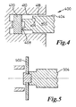
- FIG. 4 shows schematically a back extrusion apparatus 400 including a mandrel 402 having an outer surface 404 conforming to the internal shape and dimensions of the tubular side wall 20, including a step 406 corresponding to shoulder means 404 and a shallow lengthwise taper that effects minimal wall thickness according to strength requirements, as well as recess 408 corresponding to combustion bowl 30.
- a cylindrical sleeve 410 surrounds the mandrel, separated by gap 418 and relative movement between them exerts pressure on a metal slug 420 which deforms and flows into the gap and into conformity with the mandrel to define the shell body.
- the aforementioned small taper of mandrel surface 404 that creates the above discussed internal side wall taper also facilitates removal of the extruded shell. Such taper may be kept to a minimum, insofar as this is consistent with strength but may be eliminated altogether without affecting removal from the mandrel.
- extrusion in distinction from forging, casting and like operations, is a precision operation that permits the formation of relatively thin walls of relatively uniform thickness which in conjunction with the strength and stiffness afforded by the monocoque type of structure permits formation of a lightweight piston from a dense material such as steel.
- outer body shell by forging or other metal deforming processes.
- the combustion bowl wall has an axial extension in the form of flange 70.
- the mounting member could interface directly with the floor of the combustion bowl or such axial extension could be formed on the mounting member and extend to the bowl floor.
- the combustion bowl may be omitted altogether, that is, have a substantially flat or domed crown, and such flange extend from the mounting member plate to the bottom of the crown surface, such arrangement still providing the support between crown and gudgeon pin boss means and annular cooling chamber.
- central region 26 of the crown may be integral with the peripheral region 22 it need not be, and can be manufactured separately and welded into the peripheral region to effect the unitary outer shell.
- Such separate formation of a combustion bowl may be appropriate to avoid having to machine radial re-entrant features in situ, but it is, of course, not necessary for a combustion bowl to have such re-entrant features and it may have a side wall that is suitable for forming completely by the extrusion process that defines the shell.
- the piston 10 is essentially constructed from two components brought together in a single bonding operation, it is anticipated that there will still be machining operations required to the external surfaces of the side wall and crown, such as definition of combustion bowl re-entrant features, making valve pockets or recesses in the face of the crown, forming of ring grooves, cutting of the wall end and applying a final surface finish that also defines outside dimensions to within fine tolerances. Some of these may be performed before or after assembly and bonding of the outer shell and mounting member and some may be achieved during the extrusion that forms the outer shell, for example, valve pockets 90 in the crown face and ovality of cross section defined by the extrusion mandrel.
- the degree of ovality required of a piston is usually a function of its overall diameter; it is anticipated that the degree of ovality required on small diameter pistons may be achieved by the final machining of the outer surface, whereas for larger diameter pistons, such ovality may be better achieved by forming the outer shell with such cross section on a suitably shaped mandrel. Also, the formation of valve pockets or other shallow crown face features with the shell eliminates at least one relatively costly machining operation.
- Formation of the outer shell by back extrusion about a mandrel permits the tubular wall internal surface to be defined to a suitable degree of accuracy without further machining.
- Of particular importance in connection with forming a lightweight piston is that in addition to being able to cut away any non-essential parts of the tubular side wall, is to have all wall sections as thin as possible for the functions required thereof. To this end it is possible to extrude the side wall with only slight variation in thickness from end to end (other than at the shoulder means) and with the ring groove region also less thick than might be thought acceptable, because of the support from the transverse mounting member.
- the interface 57 between the mounting member and the side wall extends axially, and thus positions the mounting member radially, whereas the crown interface 71 extends radially and positions the mounting member axially.
- the bond at interface 71 which is enclosed between the mounting member and crown, must be effected by the aforementioned brazing or some other technique which does not rely upon access to it.
- One alternative is friction welding, but that may be considered unsuitable for the axially extending wall interface 57, and although the latter is accessible from the open end, and susceptible to bonding by a different technique, it may be preferred not to have different bonding systems in use together.
- piston 110 is a bonded assembly of outer shell 112 and mounting member 114, piston crown including a combustion bowl 130 therein.
- the outer shell 112 is generally similar to shell 12 insofar as it has tubular side wall 120 that includes a ring groove region 140 and shoulder means 144 and, integral therewith, a crown peripheral region 122.
- the peripheral region includes, displaced from the side wall, an axially extending combustion bowl wall 134.
- a central region 126 of the crown defined by boundary lines 128 about longitudinal axis 18, comprises the floor 132 of the combustion bowl which is of discrete formation from the peripheral region and bonded thereto at interface 133 which extends around the periphery of this central region and substantially parallel to the longitudinal axis 18.
- the combustion bowl floor 132 is carried by the mounting member 114, being formed integrally therewith and overlying a connecting rod space 164, corresponding to the connecting rod aperture 64 of member 14 of piston 10, the interface 133 that the bowl floor makes with the bowl wall comprises a crown interface.
- the mounting member 114 comprises a plate 154 carrying on the surface opposite to the combustion bowl gudgeon pin boss means 160, including transverse bore 162 and bosses 166 and 168 spaced apart by connecting rod space 164.
- the outer periphery of the member at 156 is defined to be a tight fit within the tubular side wall, in particular interfacing with the wall region 146 at wall interface 157 which extends in a substantially longitudinal direction.
- the base of the combustion bowl wall, adjacent the floor, has axial extension 170 which abuts the upper surface of the mounting member plate in order to locate it axially with respect to the crown periphery. Radial location is effected by the crown interface 133 and wall interface 157, although the wall interface 157, insofar as it is defined at shoulder means, may provide the axial location.
- the mounting member is bonded to the tubular side wall at interface 157 and to the crown at interface 133, but significantly, in addition to the wall interface 157 being in line with the open end of the side wall the crown interface 133 is in line with the open end of the combustion bowl.
- each interface is accessible in the axial direction, it is possible to weld each by laser beam, particle beam, plasma jet or the like by rotating the piston assembly or the welding apparatus about the longitudinal piston axis.
- the surfaces bounding each interface are formed to provide a small divergence in the direction from which such welding is effected.
- the line of one or both interfaces may be inclined with respect to the longitudinal axis such that one or both of the interfaces are not only visible from without the piston but may have a taper that effects both radial and axial location between the mounting member and the outer shell. It is, of course, possible to effect bonding between the outer shell and mounting member at the interfaces by brazing as described above.
- a cooling chamber 180 is defined between the outer shell and mounting member plate 154 and the plate 154 has fluid admission channel 184 and drainage channel 186 therethrough. This arrangement is shown to differ from that of piston 10 in that the chamber 180 is of greater axial extent in line with the gudgeon pin bore 162, that is, overlying the bosses 166 and 168 as shown at 167 and 169. Insofar as the admission and drainage channels are at an operationally higher level, these extended regions form reservoirs for cooling fluid.
- the fluid drainage channel may comprise one or more channels 188 extending substantially radially from the cooling chamber to the connecting rod space 164.
- Such arrangement of cooling chamber reservoirs and drainage channels may be applied to the piston 10.
- central region 126 may be defined as being other than what is substantially the whole of the combustion bowl floor. It may, for example be a smaller region of the floor or it may be larger and incorporate the bowl wall 134, the boundary between central and peripheral regions being at the upper crown surface, as shown by boundary lines 128', and the mounting member/ crown interface 133 coincident therewith, said central and peripheral regions defining together an essentially flat topped or domed crown.
- the central region of the crown may be formed with the peripheral region of the crown as part of the outer shell in the manner of piston 10 and the mounting member may have an upstanding closure to a connecting rod space in the manner of piston 110, whereby the closure provides not only upstanding flange means as described above for defining the cooling chamber but also overlies, and is capable of spreading load from, the central region of the crown.
- FIG. 3(a) to 3(d) Sectional views of a third exemplary embodiment of piston 210 in accordance with the present invention are shown in Figures 3(a) to 3(d), parts corresponding to those of Figures 1(a) to 1(d) having reference numbers increased by 200.
- the piston 210 comprises outer shell 212 and mounting member 214 bonded to each other.
- the outer shell 212 comprises a unitary body consisting of crown peripheral region 222, crown central region 226 in the form of a combustion bowl 230 and tubular side wall 220.
- the tubular side wall consists of a thicker ring groove region 240 adjacent the crown and a thinner skirt region, open ended at 224, separated from the ring groove region by simple shoulder means 244.
- the combustion bowl 230 comprises a bowl floor 232 displaced axially from the peripheral region by bowl wall 234 and the wall, at the junction with the floor, has a number of axial extensions 270 1 , 270 2 with gaps between them and possibly of slightly different axial lengths.
- Mounting member 214 comprises a relatively thin mounting plate 254, the periphery of which is dimensioned to fit within the thinner part of the side wall adjacent the shoulder means 244; the periphery 256 of the plate defines an interface 257 with the tubular wall and has no axial flange or like projection to increase the axial length of the interface.
- the upper face of the plate is substantially flat and abuts the bowl wall extensions 270 1 and 270 2 defining thereat interface 271 extending transversely with respect to the piston axis 18.
- the outer shell and mounting member in the disposition shown are bonded to each other by brazing as described above, defining the strong monocoque type of structure including a closed annular cooling chamber 280 between the crown, ring groove region of the side wall and the upper surface 255 of the mounting member plate 254.
- Fluid channel means 284 permits admission of cooling fluid into the chamber and channels 288 permit drainage by way of the gaps between the bowl wall axial extensions 270, and 270 2 to the connecting rod aperture.
- the gudgeon pin bosses 266 and 268 may extend into abutment with the side wall and the latter include through apertures 290 and 292 in alignment with the gudgeon pin bore 262. Furthermore, insofar as each boss defines an interface 294, 296 respectively with the side wall, it may be bonded thereto adjacent the apertures.
- This arrangement of longer, apertured side wall and, optionally, gudgeon pin bosses extending thereto may be applied to the piston 10, and to piston110 provided that the mounting member is bonded by brazing or the like that does not require direct access.
- the mounting means 214 is of substantially uniform cross section in the direction of the gudgeon pin bore 262, that is, as viewed in Figure 3(a), except of course where the connecting rod aperture 264 is cut. Instead of the mounting member being cast, it is formed by cutting from an extruded stock and then shaped to fit within the tubular side wall and the axially extending apertures 264 and 284 cut therein.
- FIG. 5 illustrates a disc-like slug of metal 502 is caused to rotate with a profiled mandrel 504 and during rotation the peripheral regions of the disc are displaced axially to lie along and conform with the mandrel that defines the respective wall thicknesses and shoulder means.
- the tubular side wall may be formed thereon and removed without an internal wall taper, where this can save weight.
- Such flow forming of the outer shell may be used in respect of piston 10 and 110. Although it may be preferred to define the tubular side wall with a thicker region into which ring grooves are subsequently machined, it will be appreciated that such flow forming permits, with the use of a radially contractible mandrel, formation of a tubular side wall 220' of substantially uniform thickness from end to end but varying in radius as a function of axial position to define the ring grooves 242' and shoulder means 244', as illustrated in Figure 6.
- the mounting member as bonded about the whole of its periphery to the side wall at the shoulder means, it may be bonded only at a plurality of discrete points and the periphery of the mounting member may be other than conforming in shape to the tubular side wall, extending to contact the wall only at points of bonding.
Landscapes
- Engineering & Computer Science (AREA)
- Chemical & Material Sciences (AREA)
- Combustion & Propulsion (AREA)
- Mechanical Engineering (AREA)
- General Engineering & Computer Science (AREA)
- Physics & Mathematics (AREA)
- Fluid Mechanics (AREA)
- Pistons, Piston Rings, And Cylinders (AREA)
Applications Claiming Priority (3)
| Application Number | Priority Date | Filing Date | Title |
|---|---|---|---|
| GB0018840A GB2365507B (en) | 2000-08-02 | 2000-08-02 | Engine piston and manufacture |
| GB0018840 | 2000-08-02 | ||
| PCT/GB2001/003361 WO2002010571A1 (en) | 2000-08-02 | 2001-07-26 | Engine piston and manufacture |
Publications (2)
| Publication Number | Publication Date |
|---|---|
| EP1307644A1 EP1307644A1 (en) | 2003-05-07 |
| EP1307644B1 true EP1307644B1 (en) | 2006-08-23 |
Family
ID=9896744
Family Applications (1)
| Application Number | Title | Priority Date | Filing Date |
|---|---|---|---|
| EP01984432A Expired - Lifetime EP1307644B1 (en) | 2000-08-02 | 2001-07-26 | Engine piston and manufacture |
Country Status (7)
Families Citing this family (32)
| Publication number | Priority date | Publication date | Assignee | Title |
|---|---|---|---|---|
| US6491013B1 (en) * | 2001-09-19 | 2002-12-10 | Federal-Mogul World Wide, Inc. | Closed gallery piston having reinforced oil hole |
| US6825450B2 (en) * | 2002-11-06 | 2004-11-30 | Federal-Mogul World Wide, Inc. | Piston and method of manufacture |
| US7005620B2 (en) * | 2003-11-04 | 2006-02-28 | Federal-Mogul World Wide, Inc. | Piston and method of manufacture |
| DE10358419A1 (de) | 2003-12-13 | 2005-07-14 | Audi Ag | Verfahren und Vorrichtung zur Kraftstoffdruckregelung an einer Brennkraftmaschine |
| DE102004003658A1 (de) * | 2004-01-24 | 2005-08-25 | Mahle Gmbh | Verbrennungsmulde im Boden eines Kolbens für einen Dieselmotor |
| DE102005037175A1 (de) * | 2005-08-06 | 2007-02-08 | Mahle International Gmbh | Kolben für einen Verbrennungsmotor sowie Abdeckring für den Kühlkanal eines solchen Kolbens |
| US20070074695A1 (en) * | 2005-10-04 | 2007-04-05 | Mahle Technology, Inc. | Piston having improved cooling characteristics |
| DE102005060547A1 (de) * | 2005-12-17 | 2007-06-28 | Mahle International Gmbh | Kolben für einen Verbrennungsmotor und Verfahren zu seiner Herstellung |
| US7458358B2 (en) * | 2006-05-10 | 2008-12-02 | Federal Mogul World Wide, Inc. | Thermal oxidation protective surface for steel pistons |
| DE102006027355A1 (de) * | 2006-06-13 | 2007-12-20 | Mahle International Gmbh | Kolben für einen Verbrennungsmotor und Verfahren zu dessen Herstellung |
| DE102006030699B4 (de) | 2006-06-30 | 2014-10-02 | Daimler Ag | Gegossener Stahlkolben für Verbrennungsmotoren |
| FR2918118A1 (fr) * | 2007-06-29 | 2009-01-02 | Sifcor Sa | Piston a canal de refroidissement integre notamment pour moteur diesel et son procede de fabrication |
| JP4976935B2 (ja) | 2007-07-02 | 2012-07-18 | 株式会社ニフコ | ウェザーストリップ |
| JP4379503B2 (ja) * | 2007-08-13 | 2009-12-09 | トヨタ自動車株式会社 | 内燃機関用ピストン |
| FR2925603A1 (fr) * | 2007-12-19 | 2009-06-26 | Renault Sas | Chambre de combustion pour moteur thermique suralimente a injection directe |
| DE102008062219A1 (de) * | 2008-12-13 | 2010-06-17 | Mahle International Gmbh | Kolben für einen Verbrennungsmotor |
| US20110030214A1 (en) * | 2009-08-05 | 2011-02-10 | Wolfgang Rein | Piston assembly multiple step forming process |
| US8807109B2 (en) * | 2009-11-06 | 2014-08-19 | Federal-Mogul Corporation | Steel piston with cooling gallery and method of construction thereof |
| KR101449063B1 (ko) * | 2009-11-16 | 2014-10-13 | 현대자동차주식회사 | 디젤엔진의 피스톤 및 제조방법 |
| DE102010033881A1 (de) * | 2010-08-10 | 2012-02-16 | Mahle International Gmbh | Kolben für einen Verbrennungsmotor und Verfahren zu seiner Herstellung |
| DE102011012547A1 (de) * | 2011-02-26 | 2012-08-30 | Neumayer Tekfor Holding Gmbh | Kolben-Pleuel-Anordnung |
| DE102011013141A1 (de) * | 2011-03-04 | 2012-09-06 | Mahle International Gmbh | Verfahren zur Herstellung eines Kolbens für einen Verbrennungsmotor |
| DE102011013113A1 (de) | 2011-03-04 | 2012-09-06 | Mahle International Gmbh | Kolben für einen Verbrennungsmotor und Verfahren zu seiner Herstellung |
| DE102011013067A1 (de) * | 2011-03-04 | 2012-09-06 | Mahle International Gmbh | Verfahren zur Herstellung eines Kolbens für einen Verbrennungsmotor |
| CN203584599U (zh) * | 2011-03-17 | 2014-05-07 | 康明斯知识产权公司 | 用于内燃发动机的活塞 |
| DE102011106381A1 (de) * | 2011-07-04 | 2013-01-10 | Mahle International Gmbh | Kolben für einen Verbrennungsmotor |
| KR102074774B1 (ko) * | 2012-09-27 | 2020-02-07 | 테네코 인코퍼레이티드 | 감소된 압축 높이를 가진 피스톤과 이 피스톤을 가진 피스톤 조립체 및 이 피스톤 조립체의 제작 방법 |
| US10352270B2 (en) * | 2016-03-01 | 2019-07-16 | Tenneco Inc. | Galleryless piston with connection to pockets |
| DE102016204859B3 (de) | 2016-03-23 | 2017-06-29 | Hirschvogel Umformtechnik Gmbh | Mehrteiliger Kolben für Verbrennungsmotor |
| BR112019002634A2 (pt) * | 2016-09-02 | 2019-05-28 | Ks Kolbenschmidt Gmbh | pistão constituído de uma parte interna e de uma parte externa |
| CN106735669B (zh) * | 2016-12-22 | 2022-07-05 | 滨州渤海活塞有限公司 | 一种钎焊钢活塞及制造方法 |
| EP3470655B1 (en) * | 2017-10-10 | 2020-04-22 | Lombardini S.r.l. | Piston and method of manufacturing thereof |
Family Cites Families (20)
| Publication number | Priority date | Publication date | Assignee | Title |
|---|---|---|---|---|
| US1667202A (en) | 1926-04-22 | 1928-04-24 | Ford Henry | Method of manufacturing pistons |
| GB377228A (en) * | 1931-04-22 | 1932-07-22 | David Doyle | Improvements in or relating to pistons for use in fluid pressure engines |
| US2244008A (en) | 1939-06-16 | 1941-06-03 | Gen Motors Corp | Piston construction |
| DE733038C (de) * | 1941-09-17 | 1943-03-18 | Mahle Kg | Brennkraftmaschinenkolben mit einem Hohlraum zur Aufnahme eines Kuehlmittels |
| GB558819A (en) * | 1942-07-20 | 1944-01-24 | Harry Ralph Ricardo | Improvements in or relating to the cooling of pistons |
| FR52768E (fr) * | 1943-02-25 | 1945-06-01 | Maiile Komm Ges | Piston pour moteurs à combustion interne, notamment piston conformé à la presse pour moteurs d'avions |
| DE2919638A1 (de) * | 1979-05-16 | 1980-11-20 | Schmidt Gmbh Karl | Kolben fuer brennkraftmaschinen |
| US4517930A (en) * | 1982-09-28 | 1985-05-21 | Kawasaki Jukogyo Kabushiki Kaisha | Piston of combustion engine |
| DE3430258A1 (de) * | 1984-08-17 | 1986-02-27 | Mahle Gmbh, 7000 Stuttgart | Tauchkolben fuer verbrennungsmotoren |
| JPH01178756A (ja) * | 1988-01-08 | 1989-07-14 | Mazda Motor Corp | エンジンのピストン構造 |
| GB8804533D0 (en) * | 1988-02-26 | 1988-03-30 | Wellworthy Ltd | Pistons |
| BR9001916A (pt) * | 1990-04-20 | 1991-11-12 | Metal Leve Sa | Processo de obtencao de embolo refrigerado e embolo refrigerado |
| US5413074A (en) * | 1993-07-31 | 1995-05-09 | Isuzu Motors, Ltd. | Piston and a connecting rod apparatus |
| JP2000220520A (ja) * | 1999-01-27 | 2000-08-08 | Komatsu Ltd | 内燃機関のピストン |
| US6164261A (en) * | 1999-02-10 | 2000-12-26 | Caterpillar Inc. | Internal combustion engine piston assembly and method |
| US6539910B1 (en) * | 2001-09-19 | 2003-04-01 | Federal-Mogul World Wide, Inc. | Closed gallery piston having con rod lubrication |
| US6557514B1 (en) * | 2001-10-23 | 2003-05-06 | Federal-Mogul World Wide, Inc. | Closed gallery monobloc piston having oil drainage groove |
| KR100450441B1 (ko) * | 2001-10-30 | 2004-09-30 | 삼영기계주식회사 | 역류 방지 구조를 갖는 내연기관용 피스톤조립체 |
| DE10244512A1 (de) * | 2002-09-25 | 2004-04-15 | Mahle Gmbh | Mehrteiliger gekühlter Kolben für einen Verbrennungsmotor |
| DE10257022A1 (de) * | 2002-12-06 | 2004-06-17 | Mahle Gmbh | Mehrteiliger gekühlter Kolben für einen Verbrennungsmotor |
-
2000
- 2000-08-02 GB GB0018840A patent/GB2365507B/en not_active Expired - Fee Related
-
2001
- 2001-07-26 JP JP2002516466A patent/JP4689140B2/ja not_active Expired - Fee Related
- 2001-07-26 US US10/343,499 patent/US7341037B2/en not_active Expired - Fee Related
- 2001-07-26 DE DE60122533T patent/DE60122533T2/de not_active Expired - Lifetime
- 2001-07-26 EP EP01984432A patent/EP1307644B1/en not_active Expired - Lifetime
- 2001-07-26 AU AU2002227503A patent/AU2002227503A1/en not_active Abandoned
- 2001-07-26 WO PCT/GB2001/003361 patent/WO2002010571A1/en active IP Right Grant
-
2008
- 2008-01-16 US US12/015,196 patent/US7721431B2/en not_active Expired - Fee Related
Also Published As
| Publication number | Publication date |
|---|---|
| WO2002010571A1 (en) | 2002-02-07 |
| US7341037B2 (en) | 2008-03-11 |
| US20080110335A1 (en) | 2008-05-15 |
| US20050092279A1 (en) | 2005-05-05 |
| DE60122533D1 (de) | 2006-10-05 |
| JP2004505195A (ja) | 2004-02-19 |
| DE60122533T2 (de) | 2007-04-26 |
| JP4689140B2 (ja) | 2011-05-25 |
| GB2365507B (en) | 2004-09-15 |
| GB2365507A (en) | 2002-02-20 |
| GB0018840D0 (en) | 2000-09-20 |
| US7721431B2 (en) | 2010-05-25 |
| EP1307644A1 (en) | 2003-05-07 |
| AU2002227503A1 (en) | 2002-02-13 |
Similar Documents
| Publication | Publication Date | Title |
|---|---|---|
| EP1307644B1 (en) | Engine piston and manufacture | |
| US5642654A (en) | Piston and method of manufacturing the same | |
| US6536397B2 (en) | Bonding structure of valve seat and method of making the same | |
| US5359922A (en) | Head of two welded parts for two-piece articulated piston | |
| EP1061249B1 (en) | Method and apparatus for making a two piece unitary piston | |
| US9322358B2 (en) | Piston for an internal combustion engine and method for its production | |
| JPH0399741A (ja) | 弁の製造方法 | |
| US8631573B2 (en) | Piston for an internal combustion engine and method for its production | |
| EP2969366B1 (en) | Welded piston assembly | |
| JP2009540199A (ja) | 内燃機関に用いられるピストンおよび該ピストンを製造するための方法 | |
| JP2004508490A (ja) | 内燃機関用ピストン | |
| US7941922B2 (en) | Method of manufacturing a lightweight valve | |
| US6499387B2 (en) | Unified multi-piece piston and method of manufacture | |
| EP3864276B1 (en) | Piston cooling gallery shaping to reduce piston temperature | |
| SE502382C2 (sv) | Tvådelad kolv och förfarande för framställning av denna | |
| US10711732B2 (en) | Reduced height piston | |
| US6321710B1 (en) | Diffusion joining structure | |
| EP1392470A1 (en) | Manufacturing pistons | |
| JP2005042626A (ja) | 冷却空洞付き耐摩環の製造方法 |
Legal Events
| Date | Code | Title | Description |
|---|---|---|---|
| PUAI | Public reference made under article 153(3) epc to a published international application that has entered the european phase |
Free format text: ORIGINAL CODE: 0009012 |
|
| 17P | Request for examination filed |
Effective date: 20030226 |
|
| AK | Designated contracting states |
Designated state(s): AT BE CH CY DE DK ES FI FR GB GR IE IT LI LU MC NL PT SE TR |
|
| AX | Request for extension of the european patent |
Extension state: AL LT LV MK RO SI |
|
| RAP1 | Party data changed (applicant data changed or rights of an application transferred) |
Owner name: FEDERAL-MOGUL TECHNOLOGY LIMITED |
|
| RAP1 | Party data changed (applicant data changed or rights of an application transferred) |
Owner name: FEDERAL-MOGUL TECHNOLOGY LIMITED |
|
| RBV | Designated contracting states (corrected) |
Designated state(s): DE FR GB IT |
|
| GRAP | Despatch of communication of intention to grant a patent |
Free format text: ORIGINAL CODE: EPIDOSNIGR1 |
|
| GRAS | Grant fee paid |
Free format text: ORIGINAL CODE: EPIDOSNIGR3 |
|
| GRAA | (expected) grant |
Free format text: ORIGINAL CODE: 0009210 |
|
| AK | Designated contracting states |
Kind code of ref document: B1 Designated state(s): DE FR GB IT |
|
| PG25 | Lapsed in a contracting state [announced via postgrant information from national office to epo] |
Ref country code: IT Free format text: LAPSE BECAUSE OF FAILURE TO SUBMIT A TRANSLATION OF THE DESCRIPTION OR TO PAY THE FEE WITHIN THE PRESCRIBED TIME-LIMIT;WARNING: LAPSES OF ITALIAN PATENTS WITH EFFECTIVE DATE BEFORE 2007 MAY HAVE OCCURRED AT ANY TIME BEFORE 2007. THE CORRECT EFFECTIVE DATE MAY BE DIFFERENT FROM THE ONE RECORDED. Effective date: 20060823 |
|
| REG | Reference to a national code |
Ref country code: GB Ref legal event code: FG4D |
|
| REF | Corresponds to: |
Ref document number: 60122533 Country of ref document: DE Date of ref document: 20061005 Kind code of ref document: P |
|
| ET | Fr: translation filed | ||
| PLBE | No opposition filed within time limit |
Free format text: ORIGINAL CODE: 0009261 |
|
| STAA | Information on the status of an ep patent application or granted ep patent |
Free format text: STATUS: NO OPPOSITION FILED WITHIN TIME LIMIT |
|
| 26N | No opposition filed |
Effective date: 20070524 |
|
| PGFP | Annual fee paid to national office [announced via postgrant information from national office to epo] |
Ref country code: GB Payment date: 20120625 Year of fee payment: 12 |
|
| PGFP | Annual fee paid to national office [announced via postgrant information from national office to epo] |
Ref country code: DE Payment date: 20120731 Year of fee payment: 12 Ref country code: FR Payment date: 20120712 Year of fee payment: 12 Ref country code: IT Payment date: 20120716 Year of fee payment: 12 |
|
| GBPC | Gb: european patent ceased through non-payment of renewal fee |
Effective date: 20130726 |
|
| REG | Reference to a national code |
Ref country code: FR Ref legal event code: ST Effective date: 20140331 |
|
| PG25 | Lapsed in a contracting state [announced via postgrant information from national office to epo] |
Ref country code: DE Free format text: LAPSE BECAUSE OF NON-PAYMENT OF DUE FEES Effective date: 20140201 Ref country code: GB Free format text: LAPSE BECAUSE OF NON-PAYMENT OF DUE FEES Effective date: 20130726 |
|
| REG | Reference to a national code |
Ref country code: DE Ref legal event code: R119 Ref document number: 60122533 Country of ref document: DE Effective date: 20140201 |
|
| PG25 | Lapsed in a contracting state [announced via postgrant information from national office to epo] |
Ref country code: IT Free format text: LAPSE BECAUSE OF NON-PAYMENT OF DUE FEES Effective date: 20130726 Ref country code: FR Free format text: LAPSE BECAUSE OF NON-PAYMENT OF DUE FEES Effective date: 20130731 |