EP1307014A2 - Method for summarizing default address of PNNI lowest lewel node in ATM switching system - Google Patents
Method for summarizing default address of PNNI lowest lewel node in ATM switching system Download PDFInfo
- Publication number
- EP1307014A2 EP1307014A2 EP02251726A EP02251726A EP1307014A2 EP 1307014 A2 EP1307014 A2 EP 1307014A2 EP 02251726 A EP02251726 A EP 02251726A EP 02251726 A EP02251726 A EP 02251726A EP 1307014 A2 EP1307014 A2 EP 1307014A2
- Authority
- EP
- European Patent Office
- Prior art keywords
- address
- prefix
- node
- information
- parameters
- Prior art date
- Legal status (The legal status is an assumption and is not a legal conclusion. Google has not performed a legal analysis and makes no representation as to the accuracy of the status listed.)
- Withdrawn
Links
Images


Classifications
-
- H—ELECTRICITY
- H04—ELECTRIC COMMUNICATION TECHNIQUE
- H04L—TRANSMISSION OF DIGITAL INFORMATION, e.g. TELEGRAPHIC COMMUNICATION
- H04L12/00—Data switching networks
- H04L12/28—Data switching networks characterised by path configuration, e.g. LAN [Local Area Networks] or WAN [Wide Area Networks]
-
- H—ELECTRICITY
- H04—ELECTRIC COMMUNICATION TECHNIQUE
- H04L—TRANSMISSION OF DIGITAL INFORMATION, e.g. TELEGRAPHIC COMMUNICATION
- H04L49/00—Packet switching elements
- H04L49/30—Peripheral units, e.g. input or output ports
- H04L49/3081—ATM peripheral units, e.g. policing, insertion or extraction
- H04L49/309—Header conversion, routing tables or routing tags
-
- H—ELECTRICITY
- H04—ELECTRIC COMMUNICATION TECHNIQUE
- H04Q—SELECTING
- H04Q11/00—Selecting arrangements for multiplex systems
- H04Q11/04—Selecting arrangements for multiplex systems for time-division multiplexing
- H04Q11/0428—Integrated services digital network, i.e. systems for transmission of different types of digitised signals, e.g. speech, data, telecentral, television signals
- H04Q11/0478—Provisions for broadband connections
-
- H—ELECTRICITY
- H04—ELECTRIC COMMUNICATION TECHNIQUE
- H04L—TRANSMISSION OF DIGITAL INFORMATION, e.g. TELEGRAPHIC COMMUNICATION
- H04L12/00—Data switching networks
- H04L12/54—Store-and-forward switching systems
- H04L12/56—Packet switching systems
- H04L12/5601—Transfer mode dependent, e.g. ATM
- H04L2012/5619—Network Node Interface, e.g. tandem connections, transit switching
- H04L2012/562—Routing
Definitions
- the present invention relates generally to a method for summarizing a default address of a private network-network interface lowest level node in an asynchronous transfer mode switching system, and more particularly to a method for summarizing a default address of a private network-network interface lowest level node, which is capable of summarizing the default address at the time of interfacing with a public network.
- PNNI Private Network-Network Interface
- ATM Asynchronous Transfer Mode
- the PNNI is a protocol for establishing an ATM Switched Virtual Connection (SVC) between ATM switching system, which was originally conceived for a private network using an ATM address in the form of a Network Service Access Point (NSAP) in the ATM forum.
- SVC Switched Virtual Connection
- PNNI routing is characterized in that the network configuration of a hierarchical structure is enabled and dynamic routing is supported.
- the hierarchical structure is referred to as a network structure in which more than one node are tied into a plurality of peer groups which are further tied into a plurality of upper level peer groups.
- the dynamic routing is referred to as the establishment of a connection by source routing based on topology information distributed between switching system.
- the hierarchical structure allows the large network scalability, and the dynamic routing allows the efficient use of a network resource.
- PNNI In the switching system using the PNNI, as part of the dynamic routing, reachable addresses for nodes should be dynamically exchanged between the switchers during operation of the system.
- PNNI since the PNNI has a hierarchical structure, there is a need to reduce overhead in exchange of information through a large network.
- PNNI specification 1.0 defines prefix information of 13 octets length, i.e., 104 bytes, with respect to default address summarization regarding a node address.
- the PNNI was originally conceived for the private networks.
- Korean patent laid-open No. 2001-38485 entitled “A method for reducing nodes in PNNI” is disclosed.
- the object of the above prior art is to use more efficiently the network to which the PNNI is applied and reduce the probability of failure at the time of selecting a connection path by reducing node information by use of complex node representation properly reflecting the characteristics of nodes and links within the peer groups.
- the prior art is characterized in that it comprises the steps of searching edge nodes within peer groups and defining the edge nodes reflected in internal links as ports of complex nodes, identifying parameters defining the state of each of the ports, and constructing radius, exception, and bypass for the identified parameters.
- the described prior art describes only summarization of the information on nodes and links within peer groups of the network to which the PNNI is applied, but is not contemplated for an application to the public networks.
- the default address summarization of the lowest level node is not described at all, and even any relevance to the default address summarization is not mentioned therein.
- an object of the present invention is to provide a method for summarizing a default address of a PNNI lowest level node by which a reachable address for the node can be summarized up to an internal prefix length when PNNI is applied to public networks in an ATM switching system.
- a method for summarizing a default address of private network-network interface lowest level node which is applicable to an asynchronous transfer mode (ATM) switching system employing private network-network interface (PNNI) for public networks, comprising: a first step of constructing a database for storing prefix information, node information, and reachable address information; a second step of arranging parameters inputted for creating an internal prefix to be adaptable to the system, generating the prefix information by checking the validation and address system of the parameters inputted for creating the internal prefix, and registering the prefix information in the prefix information database; a third step of generating an ATM end system address by checking the validation and address system of parameters inputted for creating the node information, and if it is determined that the ATM end system address includes internal prefix and a node address is not yet assigned from the digit state of the ATM end system address, generating the node information using the parameters for creating the node information and the ATM end system address, and registering the node
- a default address summarization function can be effectively used in an ATM switching system employing the PNNI for the public networks. Therefore, since the reachable address for the node is dynamically exchanged during a system operation, overhead in information exchange can be reduced and data related to the networks is effectively managed by automatically constructing topology information on the networks.
- Fig. 1 shows a subsystem configuration of an ATM switching system to which the present invention is applied.
- an entire subsystem is distributed by two ATM Local Switching Subsystems (ALSs) 1 and 2 interconnected by an ATM Central Switching Subsystem (ACS) 3.
- ALSs Local Switching Subsystems
- ACS ATM Central Switching Subsystem
- a transfer network consists of Access Switch Network Modules (ASNMs) 11 and 21 within the ALSs 1 and 2, an Interconnection Switch Network Module (ISNM) 31 within the ACS 3, Link Interface Modules (LIM) 13 and 32 each connected between the ASNMs 11 and 21 and the ISNM 31, and Interface Modules (IMs) 12 and 22 for a subscriber/relay line.
- ASNMs Access Switch Network Modules
- ISNM Interconnection Switch Network Module
- LIM Link Interface Modules
- a control network consists of Call and Connection Control Processors (CCCPs) 14 and 24 for processing a call/connection control function and an Operating and Maintenance Processor (OMP) 33 for processing an operating/maintenance control function.
- CCCPs 14 and 24 includes a variety of software modules for performing various call/connection control, signal protocol processing, subscriber network resource management, network node interface link resource management, internal switch link resource management, station number translation, and link and subscriber service profile data processing, etc.
- the OMP 33 includes a variety of software modules for performing an operating and maintenance function of the system, incoming number translation, route control, and route and number data processing, etc. Communication between these processors 14, 24 and 33 is accomplished through a corresponding one of the switch network modules 11, 21 and 31.
- the method for summarizing a default address of a PNNI lowest level node according to the present invention consists roughly of steps of generating a database for prefix information, node information and reachable address information, constructing an internal prefix for the PNNI lowest level node, and summarizing a default address.
- the method for summarizing a default address of the PNNI lowest level node according to the present invention can be implemented by a computer program to be stored in such a data recording medium as a CD-ROM.
- a process for generating a database for prefix information, node information and reachable address information is described.
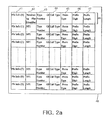
- Fig. 2a shows a prefix information database 40
- Fig. 2b shows a node information database 50
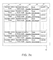
- Fig. 2c shows a reachable address information database 60.
- the prefix information database 40 has a plurality of tuples 48, each comprising a prefix information key 41, a numbering plan identifier 42, a type of number 43, a call type 44, a protocol type 45, a prefix digit 46, and a prefix length 47, and is structured in a sequential manner by the number of prefixes acceptable by the system.
- the prefix digit 46 functions as a key to allow a corresponding one of the tuples 48 to be accessed.
- the node information database 50 has a plurality of tuples 58, each comprising a node number 51, a node ID 52, a peer group ID 53, an ATM end system address (AESA) 54, a level ID 55, a leader priority 56, and a nodal flag 57, and is structured in a sequential manner by the number of nodes acceptable by the system.
- the node number 51 functions as a key to allow a corresponding one of the tuples 58 to be accessed.
- the reachable address information database 60 has a plurality of tuples 66, each comprising a reachable address prefix 61, a reachable address prefix length 62, a port identifier 63, a scope advertisement 64, and a level ID 65, and is structured in a sequential manner by the number of reachable addresses acceptable by the node.
- the reachable address functions as a key to allow a corresponding one of the tuples 66 to be accessed.
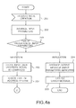
- input parameters are arranged in a form adaptable to the system in step 102 and these input parameter data are checked for their validation in step 103.
- the input parameters include a numbering plan identifier, a type of number, an authority format identifier, an address type, a call type and a prefix digit, etc.
- step 104 it is determined in step 104 which of E.164, Data Country Code (DDC) and International Code Designator (ICD) a type of address system corresponds to, and an AFI is defined for each case in steps 105 to 107.
- DDC Data Country Code
- ICD International Code Designator
- a prefix digit for Office code is constructed using the defined AFI and the prefix digit in step 108.
- the address type of the prefix is checked by means of the call type in step 109.
- step 110 it is determined in step 110 whether the address type is an internal prefix or an external prefix. If the address type is the internal prefix in step 110, the prefix digit and inputted information are registered as internal prefix information in the prefix information database 40 shown in Fig. 2a in step 111, and an output message "success" is arranged in step 113 and a processing success message is outputted in step 114, and then the process is terminated.
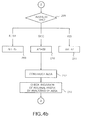
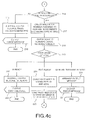
- input parameters are arranged in a form adaptable to the system in step 202.
- the input parameters include a level ID, an address type, an address, a priority, a nodal flag, etc. These input parameter data are checked for their validation in step 203.
- step 203 if the input parameters are valid, input data such as an address and nodal information are stored in the database in step 206 and the type of an address system is checked in step 207. If it is determined in step 203 that the input parameters are invalid, an output message "input parameter improper" is arranged in step 204, a processing error message is outputted in step 205, and then the process is terminated.
- step 208 which of E.164, the DDC and the ICD the type of an address system corresponds to, and an Authority and Format Identifier (AFI) is defined for each case in steps 209 to 211.
- AFI Authority and Format Identifier
- an AESA of 20 octets length is constructed in step 212.
- the inclusion of an Internal Prefix in a node address is checked by analyzing all the digits of the constructed AESA in step 213 and it is determined in step 214 whether the node address includes the internal prefix or not. It is determined in step 214 that the node address does not include the internal prefix, an output message "node creation improper" is arranged to limit the generation function of the node ID in step 215, a processing error message is outputted in step 216, and then the process is terminated.
- step 214 If it is determined in step 214 that the node address includes the internal prefix, then it is determined in step 217 whether a number assigned to a general subscriber is constructed by the AESA so as to determine whether the node address is a previously registered node address or a general subscriber number. Then, the state of numbers such as node and incoming numbers is checked in step 218. Next, according to the results of the determination and the check, it is determined in step 219 whether the Node Address is previously registered from the digit state of the AESA, it is not yet assigned, or it is a general subscriber number.
- step 219 If it is determined in step 219 that the Node Address has been previously registered, an output message "Already” representing 'in use' is arranged in step 222, a processing error message is outputted in step 223, and then the process is terminated. If it is determined in step 219 that the Node Address is assigned as the general subscriber number. An output message "general subscriber number" is arranged in step 220, a processing error message is outputted in step 221, and then the process is terminated.
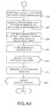
- the node ID is constructed using the level ID and the AESA of the input parameters in step 224.
- a peer group ID is constructed using the bit length of the AESA and the level ID in step 225.
- the peer group ID consists of a level ID and a prefix of an AESA, particularly a prefix having the bit length of the level ID among the prefix (13 octets) of the AESA.
- a nodal flag is constructed using a parameter related to the inputted node in step 226 and then a corresponding tuple in the node information database shown in Fig. 2b is searched and the node information is stored in step 227.
- the nodal flag is constructed in the form of an 8 bit string with first to third bits reserved and fourth to eighth bits used. For example, if a value of an inputted parameter is "True”, a corresponding bit is set to 1, and if "False", the bit is set to 0, thus constructing the 8 bit nodal flag.
- the level ID is used as a key.
- step 228 by summarizing the node address of the node information up to the bit length of an internal prefix to define the internal prefix as a default reachable summary address, summarization for default reachable address is performed in step 228. Subsequently, the summarized default reachable address is registered in the default reachable information database 60 shown in Fig. 2c in step 229 and the processing of a routing protocol with an external node is required in step 230. This allows the default summarization address of the lowest level node to be notified to the external node. Subsequently, an output message "success" is arranged in step 231, a processing success message is outputted in step 232, and then the process is terminated.
Landscapes
- Engineering & Computer Science (AREA)
- Computer Networks & Wireless Communication (AREA)
- Signal Processing (AREA)
- Data Exchanges In Wide-Area Networks (AREA)
Applications Claiming Priority (2)
| Application Number | Priority Date | Filing Date | Title |
|---|---|---|---|
| KR10-2001-0065702A KR100408649B1 (ko) | 2001-10-24 | 2001-10-24 | 에이티엠 교환시스템의 피엔엔아이 최하위 레벨 노드의디폴트 주소 요약 방법 |
| KR2001065702 | 2001-10-24 |
Publications (1)
| Publication Number | Publication Date |
|---|---|
| EP1307014A2 true EP1307014A2 (en) | 2003-05-02 |
Family
ID=19715357
Family Applications (1)
| Application Number | Title | Priority Date | Filing Date |
|---|---|---|---|
| EP02251726A Withdrawn EP1307014A2 (en) | 2001-10-24 | 2002-03-12 | Method for summarizing default address of PNNI lowest lewel node in ATM switching system |
Country Status (3)
| Country | Link |
|---|---|
| US (1) | US7065085B2 (ko) |
| EP (1) | EP1307014A2 (ko) |
| KR (1) | KR100408649B1 (ko) |
Cited By (1)
| Publication number | Priority date | Publication date | Assignee | Title |
|---|---|---|---|---|
| CN103688516A (zh) * | 2011-05-05 | 2014-03-26 | 瑞典爱立信有限公司 | 提供公共可达性的方法和有关系统与装置 |
Families Citing this family (10)
| Publication number | Priority date | Publication date | Assignee | Title |
|---|---|---|---|---|
| US7733860B2 (en) * | 2002-11-01 | 2010-06-08 | Alcatel-Lucent Canada Inc. | Method for advertising reachable address information in a network |
| US7457303B2 (en) * | 2003-06-06 | 2008-11-25 | International Business Machines Corporation | One-bounce network |
| WO2005064851A1 (en) * | 2003-12-30 | 2005-07-14 | Bce Inc. | Remotely managed subscriber station |
| CN1780251A (zh) * | 2004-11-19 | 2006-05-31 | 华为技术有限公司 | 基于自动交换光网络的域间链路识别方法 |
| US8855318B1 (en) * | 2008-04-02 | 2014-10-07 | Cisco Technology, Inc. | Master key generation and distribution for storage area network devices |
| KR101037813B1 (ko) * | 2009-09-15 | 2011-05-30 | 한상호 | 수유 가리개 |
| US9106563B2 (en) * | 2009-10-07 | 2015-08-11 | Wichorus, Inc. | Method and apparatus for switching communications traffic in a communications network |
| US20110087786A1 (en) * | 2009-10-07 | 2011-04-14 | Wichorus, Inc. | Method and apparatus for efficient resource allocation of quality of service profiles in mobile networks |
| US9385970B2 (en) * | 2009-10-07 | 2016-07-05 | Wichorus, Inc. | Method and apparatus for assigning resources in a network node |
| CN107580079B (zh) * | 2017-08-31 | 2020-12-29 | 新华三技术有限公司 | 一种报文传输方法和装置 |
Family Cites Families (9)
| Publication number | Priority date | Publication date | Assignee | Title |
|---|---|---|---|---|
| US5999517A (en) * | 1998-03-13 | 1999-12-07 | 3Com Corporation | Summarization of routing information in a hierarchical network |
| EP0980191B1 (en) | 1998-08-10 | 2009-05-20 | International Business Machines Corporation | PNNI topology abstraction |
| KR20000013859A (ko) | 1998-08-14 | 2000-03-06 | 윤종용 | 공중망 어드레스와 비동기 전송 모드 종단 시스템 어드레스 사이의 어드레스 변환 방법 |
| DE69840809D1 (de) | 1998-09-05 | 2009-06-18 | Ibm | Verfahren zur Erzeugung der optimalen complexen PNNI Knotendarstellungen in bezug auf begrenzte Kosten |
| US6246689B1 (en) | 1998-09-21 | 2001-06-12 | Lucent Technologies Inc. | Method and apparatus for efficient topology aggregation for networks with hierarchical structure |
| US6532237B1 (en) * | 1999-02-16 | 2003-03-11 | 3Com Corporation | Apparatus for and method of testing a hierarchical PNNI based ATM network |
| US6456600B1 (en) * | 1999-04-28 | 2002-09-24 | 3Com Corporation | Complex node representation in an asynchronous transfer mode PNNI network |
| KR20010038485A (ko) | 1999-10-25 | 2001-05-15 | 서평원 | 피엔엔아이에서 노드 축약 방법 |
| KR20010063094A (ko) | 1999-12-21 | 2001-07-09 | 오길록 | 차세대 인터넷에서 지름길 경로 설정이 가능한 통합목적지 이름주소해석 방법 및 장치 |
-
2001
- 2001-10-24 KR KR10-2001-0065702A patent/KR100408649B1/ko active IP Right Grant
-
2002
- 2002-03-12 US US10/096,711 patent/US7065085B2/en active Active
- 2002-03-12 EP EP02251726A patent/EP1307014A2/en not_active Withdrawn
Cited By (3)
| Publication number | Priority date | Publication date | Assignee | Title |
|---|---|---|---|---|
| CN103688516A (zh) * | 2011-05-05 | 2014-03-26 | 瑞典爱立信有限公司 | 提供公共可达性的方法和有关系统与装置 |
| US9515986B2 (en) | 2011-05-05 | 2016-12-06 | Telefonaktiebolaget Lm Ericsson (Publ) | Methods providing public reachability and related systems and devices |
| US10129208B2 (en) | 2011-05-05 | 2018-11-13 | Telefonaktiebolaget L M Ericsson (Publ) | Methods providing public reachability and related systems and devices |
Also Published As
| Publication number | Publication date |
|---|---|
| KR20030033627A (ko) | 2003-05-01 |
| US20030076833A1 (en) | 2003-04-24 |
| KR100408649B1 (ko) | 2003-12-06 |
| US7065085B2 (en) | 2006-06-20 |
Similar Documents
| Publication | Publication Date | Title |
|---|---|---|
| EP0725523B1 (en) | Transaction message routing in digital communications networks | |
| US5673263A (en) | Method for using an IP address-based routing protocol in an ATM environment | |
| JPH0685819A (ja) | コンピュータシステム | |
| JP3574184B2 (ja) | データ構造に含まれる情報の分析のための方法および装置 | |
| US20050100025A1 (en) | Network interconnection apparatus, network node apparatus, and packet transfer method for high speed, large capacity inter-network communication | |
| US7065085B2 (en) | Method for summarizing default address of PNNI lowest level node in ATM switching system | |
| EP1009130A1 (en) | Distributed directory services for locating network resources in a very large packet switching network | |
| US6243384B1 (en) | Address analysis for asynchronous transfer mode node with PNNI protocol | |
| US6201755B1 (en) | Method and system for storing and retrieving information in a communications node | |
| US7075931B2 (en) | Method and apparatus for ATM address resolution | |
| US6243383B1 (en) | Method and apparatus for ATM address resolution | |
| US7200147B2 (en) | Method for analyzing address for next generation integrated network service | |
| US7406049B2 (en) | Management of protocol information in PNNI hierarchical networks | |
| US20080037445A1 (en) | Switch name, IP address, and hardware serial number as part of the topology database | |
| KR100317121B1 (ko) | 에이티엠 교환시스템에서의 피엔엔아이 노드 관리 방법 | |
| KR100281683B1 (ko) | 비동기전송모드 교환시스템의 동적 라우팅 기반 호 경로 설정방법 및 재설정방법 | |
| KR100333735B1 (ko) | 비동기 전송 방식 교환 시스템에서의 사설 망 인터페이스 라우팅 수용 방법 | |
| KR0173377B1 (ko) | 비동기 전달 모드 가상채널교환 시스템에서 해쉬. 증가 함수와 테이블의 참조 변수를 이용한 테이블 검색방법 | |
| KR100204034B1 (ko) | 해쉬 함수와 증가함수를 이용한 테이블 데이타 할당방법 | |
| KR100317992B1 (ko) | 파라메타 그룹핑 스킴을 이용한 피엔엔아이 계층 토폴로지축약 방법 | |
| KR100553799B1 (ko) | 비동기식 전송모드 초고속 통신망에서의 가상 경로/채널연결 현행화 방법 | |
| JPH05344143A (ja) | Atm交換機における同報通信方式 | |
| CA2281752C (en) | Communications server performing protocol conversion and communication system incorporating the same | |
| KR100456975B1 (ko) | 에이티엠 망에서 피브이씨 연결을 위한 자원 할당 시스템 및 방법 | |
| KR0173379B1 (ko) | 해쉬 함수와 증가함수를 이용한 테이블 데이타 삭제방법 |
Legal Events
| Date | Code | Title | Description |
|---|---|---|---|
| PUAI | Public reference made under article 153(3) epc to a published international application that has entered the european phase |
Free format text: ORIGINAL CODE: 0009012 |
|
| AK | Designated contracting states |
Designated state(s): AT BE CH CY DE DK ES FI FR GB GR IE IT LI LU MC NL PT SE TR |
|
| AX | Request for extension of the european patent |
Extension state: AL LT LV MK RO SI |
|
| STAA | Information on the status of an ep patent application or granted ep patent |
Free format text: STATUS: THE APPLICATION IS DEEMED TO BE WITHDRAWN |
|
| 18D | Application deemed to be withdrawn |
Effective date: 20041001 |