EP1306491A2 - Verfahren und Vorrichtung zur Bildpositionierung in Erdbewegungsapplikationen - Google Patents
Verfahren und Vorrichtung zur Bildpositionierung in Erdbewegungsapplikationen Download PDFInfo
- Publication number
- EP1306491A2 EP1306491A2 EP02017039A EP02017039A EP1306491A2 EP 1306491 A2 EP1306491 A2 EP 1306491A2 EP 02017039 A EP02017039 A EP 02017039A EP 02017039 A EP02017039 A EP 02017039A EP 1306491 A2 EP1306491 A2 EP 1306491A2
- Authority
- EP
- European Patent Office
- Prior art keywords
- template
- map
- set forth
- processor
- relative
- Prior art date
- Legal status (The legal status is an assumption and is not a legal conclusion. Google has not performed a legal analysis and makes no representation as to the accuracy of the status listed.)
- Withdrawn
Links
- 238000013461 design Methods 0.000 title claims abstract description 47
- 238000000034 method Methods 0.000 title claims abstract description 18
- 238000013500 data storage Methods 0.000 claims description 17
- 238000004891 communication Methods 0.000 claims description 11
- 230000000007 visual effect Effects 0.000 claims description 3
- 238000013519 translation Methods 0.000 claims description 2
- 230000004075 alteration Effects 0.000 claims 2
- 238000005516 engineering process Methods 0.000 description 4
- 238000010276 construction Methods 0.000 description 3
- 238000012876 topography Methods 0.000 description 3
- 230000001413 cellular effect Effects 0.000 description 2
- 238000005065 mining Methods 0.000 description 2
- 238000009412 basement excavation Methods 0.000 description 1
- 238000011161 development Methods 0.000 description 1
- 238000010586 diagram Methods 0.000 description 1
- 238000012546 transfer Methods 0.000 description 1
Images



Classifications
-
- E—FIXED CONSTRUCTIONS
- E02—HYDRAULIC ENGINEERING; FOUNDATIONS; SOIL SHIFTING
- E02F—DREDGING; SOIL-SHIFTING
- E02F9/00—Component parts of dredgers or soil-shifting machines, not restricted to one of the kinds covered by groups E02F3/00 - E02F7/00
- E02F9/20—Drives; Control devices
- E02F9/2025—Particular purposes of control systems not otherwise provided for
- E02F9/2045—Guiding machines along a predetermined path
-
- E—FIXED CONSTRUCTIONS
- E02—HYDRAULIC ENGINEERING; FOUNDATIONS; SOIL SHIFTING
- E02F—DREDGING; SOIL-SHIFTING
- E02F9/00—Component parts of dredgers or soil-shifting machines, not restricted to one of the kinds covered by groups E02F3/00 - E02F7/00
- E02F9/26—Indicating devices
-
- G—PHYSICS
- G01—MEASURING; TESTING
- G01S—RADIO DIRECTION-FINDING; RADIO NAVIGATION; DETERMINING DISTANCE OR VELOCITY BY USE OF RADIO WAVES; LOCATING OR PRESENCE-DETECTING BY USE OF THE REFLECTION OR RERADIATION OF RADIO WAVES; ANALOGOUS ARRANGEMENTS USING OTHER WAVES
- G01S1/00—Beacons or beacon systems transmitting signals having a characteristic or characteristics capable of being detected by non-directional receivers and defining directions, positions, or position lines fixed relatively to the beacon transmitters; Receivers co-operating therewith
Definitions
- the present invention relates to the design and construction of earthworks by work machines and, more particularly, to the development and storage of earthwork design templates for placement by the machine operator on a topographic map.
- At least one design template is electronically stored on an onboard computer system on a work machine.
- the operator of the machine may select one or more design templates and place the templates on a topographic map, also electronically stored in the onboard computer system.
- To place the template the operator translates the template into position, orients the direction of the template, and determines the appropriate elevation of the template on the topographic map.
- FIG. 1 A system for storing and placing design templates according to the preferred embodiment of the present invention is illustrated in Fig. 1 and generally designated 10.
- a work machine such as a track-type tractor, road grader, paver, or the like.
- the present invention is described in connection with the design and placement of artillery emplacements.
- the present invention is equally well-suited for use with other means for planning and altering terrain and for many terrain-altering uses, such as mining operations, constructions sites, or the like.
- the system 10 preferably includes an onboard component 100 and an office component 102.
- the onboard component 100 is preferably mounted on the work machine such that it is accessible by an operator of the machine. Alternatively, the onboard component 100 may be located remotely from the work machine.
- the onboard component 100 includes a processor 104, data storage system 106 , display 108, and communications system 110.
- the processor 104 controls the functions of the onboard component 100 and processes data received from or sent to the office component 102.
- the data storage system 106 includes template storage 112 for electronically storing at least one design template, map storage 114 for storing a topography map which encompasses the general area of ground to be worked, and template position storage 116 for storing the position in three-dimensions of the at least one design template on the map.
- the data storage system 106 is accessed by the processor 104.
- the display 108 provides the operator with visual representations of the data stored in the data storage system 106 to guide the operator in operating the machine to create the earthworks.
- the display 108 preferably accepts input from the operator to allow the operator to modify the template position data stored in the data storage system 106, such as by being touch-sensitive.
- a keyboard or other input device may be included in the on-board component 100 and connected to the processor 104 to allow the operator to provide input and modify the template position data.
- the communication system 110 communicates with the office component 102 of the system 10.
- the communication system 110 communicates by wireless means, such as satellite or cellular technology, which are well known by those skilled in the art.
- the office component 102 of the system 10 is preferably located remotely from the work machine.
- the office component 102 includes a processor 118, a data storage system 120, a design system 122, and a communications system 124.
- the processor 118 controls the functions of the office component 102 and processes data received from or sent to the onboard component 100.
- the data storage system 120 includes a design template storage 126 for electronically storing at least one design template.
- the template design system 122 preferably through input by an operator, designs the earthwork design templates.
- the communication system 124 communicates with the onboard component 100 of the system 10.
- the communication system 124 communicates by wireless means, such as satellite or cellular technology, which are well known by those skilled in the art.
- design placement system 10 Operation of design placement system 10 is controlled by software that is programmed into the onboard and office processors 104 and 118 by external means. Alternately, the program can be implemented via hardware or any other programming technique. Creation of this software based upon the description set forth in the specification is within the capabilities of one having ordinary skill in the programming arts.
- One or more work machines are delivered to a work site.
- at least one design template is stored in the data storage system 106 of the onboard component 100 on the work machine 128.
- the at least one design template is created off-site utilizing the office component 102 of the system 10.
- the template is created within the template design system 122, a process well known to those skilled in the art and which will not be described herein.
- the template is stored in the data storage system 120 of the office component 102.
- one component 100 or 102 contacts the other by way of its communication system 110 or 124. Either the onboard or the office component 100 or 102 may initiate contact with the other.
- a copy of the design template is transferred via the communication systems 110 and 124 to the onboard data storage system 106, where it is stored in the design template storage 112.
- the design template may be transferred to the onboard component 100 by other means, such as by transferring the file by means of a disk or other fixed media.
- a topographic map of the terrain is developed 130 and stored in the map storage 114 in the data storage system 106 of the onboard component 100.
- the methods of developing a topographic map are well known to those of ordinary skill in the art and will not be described herein.
- the topographic map may be developed prior to the transfer of the design template to the onboard component 100.
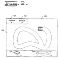
- the display 108 of the onboard component 100 preferably displays a visual representation of the of the map data 150 and the template data 152 (hereinafter known as the map and the template) stored in the data storage system 106, as seen in Fig. 3.
- the map and the template the template data 152
- two design templates 152 are shown as being stored and displayed by the onboard component 100.
- the present invention anticipates that additional or fewer templates 152 may be stored and displayed.
- the operator selects one of the design templates 152, preferably by touching the display 132.
- the stored templates 152 will be shown on the display 108 and a selection of corresponding buttons 154 will be displayed across the top of the display 108. If the display 108 is touch-sensitive, the desired template 152 may be selected by touching the appropriate button 154.
- a keyboard (not shown) or other input device may be included in the onboard component 100 to accept operator input and to allow the operator to select one of the design templates 152 and otherwise interact with the onboard component 100.
- the design template 152 is shown on the display 108 overlaid on the map 150.
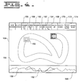
- the operator positions the template 152 in the x-y plane in a desired location on the map 150, as seen in Fig. 4 134.
- the display 108 being touch-sensitive, displays a series of buttons 156, 158, 160, and 162 to allow the operator to move the design horizontally or vertically on the two-dimensional representation of the map 150.
- At least one anchor point is selected on the template 152. This point may be designated by the operator of the machine, or it may have been designated during the creation of the design template 152 in the template design system 122.
- an origin point is selected on the map 150. This selection is preferably made by the processor 104 based upon the input of the operator utilizing the translation buttons 156, 158, 160, and 162. Once the origin point is selected, the template 152 is moved across the map 150 such that its anchor point overlays the origin point. If the operator desires to adjust the horizontal or vertical position of the template 152, he may, by pressing the buttons 156, 158, 160, or 162 on the display 108, further adjust the position of the origin point. As the origin point moves, the anchor point, and thus the template 152 itself, moves such that the anchor point continues to overlay the origin point.
- a design heading is selected.
- the operator selects the heading by pressing the rotate design button 164 on the display 108.
- the template 152 is initially placed on the map 150 with a heading of zero such that it is oriented along the y-axis.
- the template 152 may be initially positioned on the map 130 to correspond with the current machine heading.
- the rotate design button 164 As the operator pushes the rotate design button 164, the template 152 rotates about its anchor point.
- a second point on the template 152 may be designated as a rotation point.
- Each push of the button 164 preferably corresponds to a fixed number of degrees of rotation, such as each push of the button 164 being equivalent to 12°.
- each push of the buttons 168 and 170 corresponds to the template 152 being elevated or lowered a fixed distance; for example, each push of the buttons 168 and 170 may move the template 152 one foot.
- the slope value and cross slope value are selected to orient the template for three-dimensional positioning 144.
- These values may be automatically selected by the processor 104 if the template 152 is to be kept level, or they may be selected by the operator utilizing the rotate slope and rotate cross slope buttons 172 and 174.
- the template 152 rotates out of the x-y plane, with, preferably, each push of the buttons 172 and 174 corresponding to a fixed number of degrees; for example, each push of the buttons 172 and 174 may correspond to 3° of rotation.
- the template 152 may rotate about its longitudinal center axis as the cross slope is changed and about its transverse center axis as the slope is changed.
- the template 152 may rotate about axes containing the anchor, or other designated, point.
- the change in slope preferably can be seen by the operator in the profile view 166 seen along the bottom of the display 108, in which the profile of the earthwork is overlaid on the profile of topography of the site.
- the operator may elevate and orient the template 152 to take advantage of the natural terrain, thus minimizing the excavation and fill work needed when creating the design at the site.
- the operator may repeat the process by selecting the same or another template 152 to place on the map 150 if additional earthworks are required, as seen in Fig. 5. Otherwise, the location of the placed templates 152 may be stored in the template position storage 112 in the data storage system 106, if so desired.
- the operator may create the earthworks at the worksite.
- the present invention provides an efficient means for designing earthwork placement at a work site. In many situations, it is inconvenient to connect work machines to a back office system to download the earthwork layout for the work site, especially as in many instances work machines may be brought into small sites to construct a few earthworks (perhaps a task of a few hours duration).
- the earthworks layout may be designed "on the fly.”
- Standard design templates may be stored on the machine; then when the work machine is delivered to the site, no further communication with the office system is necessary.
- the topography map may be developed, and the operator may place the standard templates on the map, translating and orienting them to the desired x-y coordinates and adjusting their elevation, slope, and cross slope to suit the overall plan and the current terrain. Then the operator can create the earthworks following the design, all without the delay inherent in waiting for the site design to be completed in an off-site office.
Landscapes
- Engineering & Computer Science (AREA)
- Mining & Mineral Resources (AREA)
- Civil Engineering (AREA)
- General Engineering & Computer Science (AREA)
- Structural Engineering (AREA)
- Physics & Mathematics (AREA)
- Computer Networks & Wireless Communication (AREA)
- General Physics & Mathematics (AREA)
- Radar, Positioning & Navigation (AREA)
- Remote Sensing (AREA)
- Processing Or Creating Images (AREA)
- Retaining Walls (AREA)
- Management, Administration, Business Operations System, And Electronic Commerce (AREA)
Applications Claiming Priority (2)
| Application Number | Priority Date | Filing Date | Title |
|---|---|---|---|
| US09/974,286 US6751540B2 (en) | 2001-10-10 | 2001-10-10 | Method and apparatus for design placement for earthmoving applications |
| US974286 | 2001-10-10 |
Publications (2)
| Publication Number | Publication Date |
|---|---|
| EP1306491A2 true EP1306491A2 (de) | 2003-05-02 |
| EP1306491A3 EP1306491A3 (de) | 2010-01-27 |
Family
ID=25521848
Family Applications (1)
| Application Number | Title | Priority Date | Filing Date |
|---|---|---|---|
| EP02017039A Withdrawn EP1306491A3 (de) | 2001-10-10 | 2002-07-29 | Verfahren und Vorrichtung zur Bildpositionierung in Erdbewegungsapplikationen |
Country Status (2)
| Country | Link |
|---|---|
| US (1) | US6751540B2 (de) |
| EP (1) | EP1306491A3 (de) |
Families Citing this family (10)
| Publication number | Priority date | Publication date | Assignee | Title |
|---|---|---|---|---|
| WO2004027164A1 (ja) * | 2002-09-17 | 2004-04-01 | Hitachi Construction Machinery Co., Ltd. | 建設機械の掘削作業教示装置 |
| WO2005036331A2 (en) * | 2003-09-12 | 2005-04-21 | Carlson Software, Inc. | Fluvial geomorphic landscape design computer software |
| US7400959B2 (en) | 2004-08-27 | 2008-07-15 | Caterpillar Inc. | System for customizing responsiveness of a work machine |
| US20070239338A1 (en) * | 2006-04-06 | 2007-10-11 | Dean Potts | Worksite preparation method using compaction response and mapping information |
| US7731450B2 (en) * | 2006-09-07 | 2010-06-08 | Caterpillar Inc. | Method of operating a compactor machine via path planning based on compaction state data and mapping information |
| US7908062B2 (en) | 2007-02-28 | 2011-03-15 | Caterpillar Inc. | System and method for preparing a worksite based on soil moisture map data |
| US8144245B2 (en) * | 2007-02-28 | 2012-03-27 | Caterpillar Inc. | Method of determining a machine operation using virtual imaging |
| US8793055B2 (en) * | 2007-07-13 | 2014-07-29 | Volvo Construction Equipment Ab | Method for providing an operator of a work machine with operation instructions and a computer program for implementing the method |
| US9891605B2 (en) * | 2014-08-06 | 2018-02-13 | Caterpillar Inc. | Grade control cleanup pass using volume constraints |
| USD847836S1 (en) | 2016-08-24 | 2019-05-07 | Caterpillar Inc. | Display panel with graphical user interface |
Citations (2)
| Publication number | Priority date | Publication date | Assignee | Title |
|---|---|---|---|---|
| WO1995030880A1 (en) | 1994-05-10 | 1995-11-16 | Caterpillar Inc. | Method and apparatus for monitoring material removal using mobile machinery |
| US5631658A (en) * | 1993-12-08 | 1997-05-20 | Caterpillar Inc. | Method and apparatus for operating geography-altering machinery relative to a work site |
Family Cites Families (11)
| Publication number | Priority date | Publication date | Assignee | Title |
|---|---|---|---|---|
| JPH0689325A (ja) * | 1991-07-20 | 1994-03-29 | Fuji Xerox Co Ltd | 図形表示方式 |
| US5375663A (en) | 1993-04-01 | 1994-12-27 | Spectra-Physics Laserplane, Inc. | Earthmoving apparatus and method for grading land providing continuous resurveying |
| US5517419A (en) | 1993-07-22 | 1996-05-14 | Synectics Corporation | Advanced terrain mapping system |
| US5964298A (en) | 1994-06-13 | 1999-10-12 | Giganet, Inc. | Integrated civil engineering and earthmoving system |
| JP3364856B2 (ja) * | 1994-11-09 | 2003-01-08 | 鹿島建設株式会社 | 遠隔施工の作業支援画像システム |
| US5560431A (en) | 1995-07-21 | 1996-10-01 | Caterpillar Inc. | Site profile based control system and method for an earthmoving implement |
| US6195604B1 (en) | 1996-09-09 | 2001-02-27 | Agco Limited | Tractor with monitoring system |
| US6295066B1 (en) * | 1997-09-12 | 2001-09-25 | Hitachi, Ltd. | Method for generating virtual three-dimensional space |
| US6212471B1 (en) | 1999-04-28 | 2001-04-03 | Lockheed Martin Corporation | Dynamic optimal sensor employment for searching an area |
| US6037901A (en) | 1999-05-17 | 2000-03-14 | Caterpillar Inc. | System and method for communicating information for fleets of earthworking machines |
| US6191732B1 (en) | 1999-05-25 | 2001-02-20 | Carlson Software | Real-time surveying/earth moving system |
-
2001
- 2001-10-10 US US09/974,286 patent/US6751540B2/en not_active Expired - Lifetime
-
2002
- 2002-07-29 EP EP02017039A patent/EP1306491A3/de not_active Withdrawn
Patent Citations (2)
| Publication number | Priority date | Publication date | Assignee | Title |
|---|---|---|---|---|
| US5631658A (en) * | 1993-12-08 | 1997-05-20 | Caterpillar Inc. | Method and apparatus for operating geography-altering machinery relative to a work site |
| WO1995030880A1 (en) | 1994-05-10 | 1995-11-16 | Caterpillar Inc. | Method and apparatus for monitoring material removal using mobile machinery |
Also Published As
| Publication number | Publication date |
|---|---|
| US6751540B2 (en) | 2004-06-15 |
| EP1306491A3 (de) | 2010-01-27 |
| US20030069679A1 (en) | 2003-04-10 |
Similar Documents
| Publication | Publication Date | Title |
|---|---|---|
| CN100443674C (zh) | 作业机械的作业支援·管理系统 | |
| US8817238B2 (en) | Three dimensional feature location from an excavator | |
| JP6578366B2 (ja) | 施工管理システム | |
| AU767738B2 (en) | Real-time surveying/earth moving system | |
| JP6567940B2 (ja) | 施工管理システム | |
| AU2021258061A1 (en) | Construction management system and construction management method | |
| US11414839B2 (en) | Display control device and method for generating target line or control line of work machine | |
| AU2016201912B2 (en) | Automated material tagging system | |
| EP0780799B1 (de) | Positionierung eines Eingabezeigers | |
| US6751540B2 (en) | Method and apparatus for design placement for earthmoving applications | |
| CN111226007A (zh) | 施工管理装置、显示装置及施工管理方法 | |
| AU2008300440B2 (en) | Method and software product for designing drilling pattern for rock cavity excavation | |
| JPH08506870A (ja) | 作業場所に対して地形変更マシンを操作する方法と装置 | |
| JPH1136373A (ja) | 作業現場に対し地形変更機械を操作するための方法と装置 | |
| WO2016111148A1 (ja) | 施工情報表示装置および施工情報の表示方法 | |
| JP2016212469A (ja) | 施工計画システム | |
| JP7816696B2 (ja) | 支援システム、情報処理装置、プログラム | |
| US20130054075A1 (en) | Location Control System for Feature Placement | |
| US20080091520A1 (en) | Work Management System and Working Machine Equipped With the Same | |
| US20060042804A1 (en) | Work implement rotation control system and method | |
| WO2022168447A1 (ja) | 自動作業システム | |
| JP7317926B2 (ja) | 施工管理装置、表示装置および施工管理方法 | |
| JP7107792B2 (ja) | 建設機械 | |
| US11761173B2 (en) | Systems and methods for building a pad | |
| CN112031052B (zh) | 推土机施工管控系统及方法 |
Legal Events
| Date | Code | Title | Description |
|---|---|---|---|
| PUAI | Public reference made under article 153(3) epc to a published international application that has entered the european phase |
Free format text: ORIGINAL CODE: 0009012 |
|
| AK | Designated contracting states |
Designated state(s): AT BE BG CH CY CZ DE DK EE ES FI FR GB GR IE IT LI LU MC NL PT SE SK TR |
|
| AX | Request for extension of the european patent |
Extension state: AL LT LV MK RO SI |
|
| RIC1 | Information provided on ipc code assigned before grant |
Ipc: E02F 9/26 20060101ALI20090916BHEP Ipc: E02F 9/20 20060101AFI20030311BHEP |
|
| PUAL | Search report despatched |
Free format text: ORIGINAL CODE: 0009013 |
|
| AK | Designated contracting states |
Kind code of ref document: A3 Designated state(s): AT BE BG CH CY CZ DE DK EE ES FI FR GB GR IE IT LI LU MC NL PT SE SK TR |
|
| AX | Request for extension of the european patent |
Extension state: AL LT LV MK RO SI |
|
| AKX | Designation fees paid |
Designated state(s): AT BE BG CH CY CZ DE DK EE ES FI FR GB GR IE IT LI LU MC NL PT SE SK TR |
|
| 17P | Request for examination filed |
Effective date: 20100727 |
|
| 17Q | First examination report despatched |
Effective date: 20101006 |
|
| STAA | Information on the status of an ep patent application or granted ep patent |
Free format text: STATUS: THE APPLICATION IS DEEMED TO BE WITHDRAWN |
|
| 18D | Application deemed to be withdrawn |
Effective date: 20131002 |