Background of the Invention
Field of the Invention
-
The present invention relates to a window member for
chemical mechanical polishing and a polishing pad. More
particularly, the present invention relates to a window member
for chemical mechanical polishing excellent in antifouling
property and transparency, and a polishing pad using the same,
and also to a window member for chemical mechanical polishing
excellent also in anti-scratching and a polishing pad using the
same.
Description of the prior art
-
When a semiconductor wafer is polished using a slurry by
chemical mechanical polishing, a polishing pad is fixed on a
surface plate of a polishing apparatus and, on the other hand, a
semiconductor wafer is fixed on a lower end of a pressure head
and this semiconductor wafer is abutted against the polishing
pad while pressing under a prescribed pressure. And, it is
known that polishing is performed by sliding a semiconductor
wafer and a polishing pad by rotating the surface plate and the
pressure head while a slurry is added dropwise on the surface
plate at a prescribed amount from a slurry supplying part. As
this polishing pad, a resin such as polyurethane is usually used.
-
However, in this conventional polishing pad, there were
problems that the surface of the polishing pad is deteriorated,
damaged or colored by repeating polishing and, thus, durability
and antifouling property are not sufficient.
-
In addition, recently, an optical endpoint detecting
apparatus and a detecting method that are using an optical
method by which the state of a polished surface can be directly
observed disclosed in, for example, JP-A-9-7985 and JP-A-2000-3262
are known.
-
In these optical endpoint detecting apparatus and methods,
generally, a window member through which a light for detecting
an endpoint can transmit as disclosed in, for example, JP-A-11-512977,
and which is comprised of a hard and uniform resin, is
formed in a polishing pad, and a surface to be polished is
observed through this window member.
-
As a material constituting this window member, usually,
various resins are used. However, there are problems that the
surface of the window member is damaged or colored by repeating
chemical mechanical polishing and, thus, endpoint detection is
interfered.
Summary of the Invention
-
The present invention solves the above-mentioned problems
and an object of the present invention is to provide a window
member for chemical mechanical polishing excellent in
antifouling property and transparency, and is excellent also in
anti-scratching and a polishing pad using the same. Further,
another object of the present invention is to provide a window
member for chemical mechanical polishing leads to an easy
detection a polishing endpoint of the semiconductor wafer
surface by transmitting a light for endpoint detection, for
polishing of a semiconductor wafer using an optical endpoint
detecting apparatus.
-
The present invention is based on the findings described
above and can be described as follows.
- 1. A window member for chemical mechanical polishing
comprising a substrate part which is transparent partially or
all, and an antifouling resin layer formed on at least one side
of the substrate part.
- 2. The window member for chemical mechanical polishing
according to 1 above, wherein the substrate part is comprised of
at least one resin selected from the group consisting of a
polyester resin, a triacetylcellulose resin, a polycarbonate
resin, an allylcarbonate resin, a polyethersulfone resin, a
polyacrylate resin, a norbornene resin, an acrylstyrene resin, a
polyurethane resin and a polyolefin resin.
- 3. The window member for chemical mechanical polishing
according to 1 or 2 above, wherein the antifouling resin layer
is comprised of a fluorine-based polymer having a polysiloxane
segment in a main chain.
- 4. The window member for chemical mechanical polishing
according to any one of 1 to 3 above, wherein the antifouling
resin layer is cured a curable resin composition comprising an
olefin-based polymer having a polysiloxane segment in a main
chain, whose content of fluorine is 20wt% or more, and whose
molecular weight is 5,000 or more reduced to polystyrene, and a
crosslinkable compound.
- 5. The window member for chemical mechanical polishing
according to 4 above, wherein the olefin-based polymer has a
hydroxyl group and/or an epoxy group.
- 6. A polishing pad comprising the window member for
chemical mechanical polishing as described in any one of 1 to 5
above.
- 7. The polishing pad according to 6 above, wherein the
window member for chemical mechanical polishing is fixed to a
through hole of a substrate for a polishing pad provided with
the through hole penetrating from surface to back, or is adhered
to the substrate for a polishing pad so as to cover an opening
part of the through hole.
- 8. The polishing pad according to 6 above, wherein the
window member for chemical mechanical polishing is inserted
between two or more divided substrates for a polishing pad.
- 9. The polishing pad according to 7 or 8 above, further
comprising a supporting layer laminated on a back of the
substrate for a polishing pad.
- 10. The polishing pad according to any one of 7 to 9
above, wherein the substrate for a polishing pad is disc-like or
a belt-like.
-
Effects of the Invention
-
The window member for chemical mechanical polishing of
the present invention is excellent in antifouling property and
transparency, and is excellent also in anti-scratching.
Therefore, with the window member for chemical mechanical
polishing of the present invention excellent in antifouling
property, a polishing pad to perform an optical endpoint
detection stably can be provided.
-
When the polishing pad of the present invention is used,
since the surface of the window member is not stained or
slightly stained in use of a slurry for chemical mechanical
polishing, optical endpoint detection can be stably performed.
Since the present polishing pad is also excellent in anti-scratching.
the optical endpoint detection can be further stably
performed even by repetitive use.
Detailed description of the Invention
-
The present invention will be explained in detail.
1. Window member for chemical mechanical polishing
-
The window member for chemical mechanical polishing of
the present invention (hereinafter, also referred to as simply
"window member") is a member having light transmitting
properties, which is used as a monitoring window in order to
detect a polishing endpoint during chemical mechanical polishing
of materials to be polished, and a window member 12 composed of
a substrate part 12a which is transparent partially or all, and
an antifouling resin layer 12b formed on at least one side
thereof, for example, shown in Fig.1. The antifouling resin
layer 12b is usually formed on one side thereof, but the layer
may be formed only on the surface of a transparent part of the
side.
(Substrate part)
-
The substrate is the one which is transparent to a light
partly at least, and the word "transparent" is used in a broad
sense including colored and transparent, and translucent. It is
preferable that the transparency is higher. In addition, at
least a part of this substrate part may be transparent, that is,
a whole substrate part may be transparent, or a part of the
substrate may be transparent. When a part of the substrate part
is transparent, it is sufficient that the light for endpoint
detection transmits through the part.
-
As a material constituting the "substrate part"
(hereinafter, also referred to as "substrate part material"), a
thermoplastic resin, a thermosetting resin, an elastomer and a
rubber which give light transmitting properties can be used.
Alternatively, a glass may be used. It is preferable that the
substrate part has a flexibility from viewpoints of the
polishing condition, the adherability to a substrate for a
polishing pad, the workability in exchanging window members if
necessary and the like. In particular, in the case of belt type
polishing apparatus, it is particularly preferable that the
substrate part has a flexibility. From a viewpoint of the
flexibility, a thermoplastic resin, an elastomer and a rubber
are preferable.
<Substrate part material>
-
Examples of the thermoplastic resin include a polyolefin-based
resin, a polystyrene-based resin, an acrylic-based resin
[including a (meth)acrylate-based resin], a vinyl ester resin
(except for an acrylic resin), a polyester-based resin, a
polyamide-based resin, a fluorine resin, a polycarbonate resin,
a polyacetal resin and the like. And, examples of the
thermosetting resin include a phenol resin, an epoxy resin, an
unsaturated polyester resin, a polyurethane resin, a
polyurethane-urea resin and a urea resin, a silicone resin and
the like. Among them, from viewpoints of the light transmitting
properties and the durability, a polyester resin, a
triacetylcellulose resin, a polycarbonate resin, an
allylcarbonate resin, a polyethersulfone resin, an acrylic resin,
a norbornene resin, an acrylstyrene resin, a polyurethane resin
and a polyolefin resin are preferable.
-
Further, examples of the elastomer include styrene-based
elastomers such as a styrene-butadiene-styrene block copolymer
(SBS) and a hydrogenated block copolymer thereof (SEBS),
thermoplastic elastomers such as a polyolefin elastomer (TPO), a
thermoplastic polyurethane elastomer(TPU), a thermoplastic
polyester elastomer (TPEE), a polyamide elastomer (TPAE) and a
diene-based elastomer (1,2-polybutadiene etc.), a silicone
resin-based elastomer, a fluorine resin-based elastomer and the
like.
-
In addition, examples of the rubber include a butadiene
rubber, a styrene-butadiene rubber, an isoprene rubber, an
isobutylene-isoprene rubber, an acrylic rubber, an
acrylonitrile-butadiene rubber, an ethylene-propylene rubber, an
ethylene-propylene-diene rubber, a silicone rubber, a fluorine
rubber and the like.
-
The substrate part material may be modified with at least
one kind of an acid anhydride group, a carboxyl group, a
hydroxyl group, an epoxy group and an amino group. By
modification, the affinity with an abrasive, an aqueous medium
and the like constituting a slurry can be regulated. In
addition, these substrate part materials may be used in
combination of two or more.
-
The substrate part material may be a crosslinked polymer
or a noncrosslinked polymer and it is not particularly limited.
But it is preferable that at least a part thereof is a
crosslinked polymer (including a case wherein a material made of
a mixture of two or more components and at least a part of at
least one of the components is a crosslinked polymer and a case
wherein a material made of one component and at least a part of
the component is a crosslinked polymer).
-
By having a crosslinked structure in at least a part of
the substrate part material, the elastic recovery property is
given to the substrate part. Therefore, a displacement by
stress applied to a polishing pad during polishing can be
suppressed, and excess stretching of a substrate part during
polishing and dressing and burial of pores due to plastic
deformation can be prevented. For this reason, the retaining of
a slurry during polishing is better, and recovery of the
retaining of the slurry by dressing is easy.
-
Consequently examples of the crosslinked polymer include,
among the above-mentioned thermoplastic resin, thermosetting
resin, elastomer and rubber which give light transmitting
properties, polymers obtained by crosslinking resins such as a
polyurethane resin, an epoxy resin, a polyacrylic resin, an
unsaturated polyester resin and a vinyl ester resin (except for
a polyacrylic resin), a diene-based elastomer such as 1,2-polybutadiene,
rubbers such as a butadiene rubber, an isoprene
rubber, an acrylic rubber, an acrylonitrile-butadiene rubber, a
styrene-butadiene rubber, an ethylene-propylene rubber, a
silicone rubber, a fluorine rubber and a styrene-isoprene rubber,
and polymers obtained by crosslinking polyethylene,
polyvinylidene fluoride and the like (by a crosslinkable agent,
irradiation of ultraviolet-ray, electron beam or the like).
Besides, an ionomer and the like may be used.
-
Among these polymers, a polyurethane resin and
crosslinked 1,2-polybutadiene are particularly preferred,
because they can give sufficient light transmitting properties,
and are stable against a strong acid or a strong alkali
contained in many slurries and, further, little softening due to
water absorption. This crosslinked 1,2-polybutadiene may be
used by blending other rubbers such as a butadiene rubber and an
isoprene rubber.
(Shape of substrate part)
-
A shape of the substrate part is not particularly limited,
but various shapes can be used according to an object and a
utility. For example, a substrate part 12a may be massive-like
(see Fig.1, Fig.3, Fig.4, Fig.10 etc.), plate-like, disc-like or
sheet-like (see Fig.8, Fi.12 etc.), belt-like (see Fig.2,
Figs.23 - 28), long film-like (string-like) or long sheet-like.
In addition, a shape of a longitudinal cross section of the
substrate may be rectangular (see Fig.1 and Fig.8), reverse T
letter-like (see Fig.4 etc.), T letter-like (see Fig.6 etc.) and
so on. This belt-like shape shown in Fig.2 can be usually
applied to a belt-like polishing pad as shown in Fig.27.
Further, a thickness of the substrate part itself can be made to
be small by providing a concave part 13 thereon (see for example
Fig.11). Thereby, the light transmitting properties of this
substrate part itself can be enhanced.
(Antifouling resin layer)
-
It is preferable that the antifouling resin layer is
provided with a part having the transparency explained for the
above-mentioned substrate part. Further, an antifouling resin
layer is preferably such that at least a part of a window member
comprised of the above-mentioned substrate part and the
antifouling resin layer has light transmitting properties.
-
The antifouling resin layer may be made of any materials
as long as they do not contaminate the surface of the layer due
to attachment of a slurry component, a polishing wastage, or an
abrasion dust of a polishing pad. In the present invention, the
antifouling resin layer can be made of a fluorine-based resin
polymer having a polysiloxane segment in a main chain.
<Fluorine-based polymer>
-
The preferred fluorine-based polymer is an olefin-based
polymer (hereinafter, also referred to as "specific fluorine-based
polymer") which has a polysiloxane segment in a main chain,
whose content of fluorine is 30wt% or more, and whose number-average
molecular weight is 5,000 or more reduced to polystyrene
by GPC method. The specific fluorine-based polymer is an
olefin-based polymer having a polysiloxane segment represented
by the following general formula (1) in a main chain, and a
ratio of the polysiloxane segment in the specific fluorine-based
polymer is usually 0.1 to 10mol%.
wherein R
1 and R
2 may be the same or different, and denote a
hydrogen atom, an alkyl group, a halogenated alkyl group or an
aryl group.
-
The fluorine content is preferably 30wt% or more, more
preferably 40 to 60wt% in the specific fluorine-based polymer
and the number-average molecular weight is preferably 5,000 or
more, more preferably 10,000 to 500,000.
-
Here, the fluorine content is a value measured by the
alizarin complexoen method, and the number-average molecular
weight is a value when tetrahydrofuran is used as an eluate.
-
The specific fluorine-based polymer in the present
invention can be obtained by reacting (a) a fluorine-containing
olefin compound (hereinafter, referred to as "component (a)"),
(b) a compound copolymerizable with the component (a)
(hereinafter, referred to as "component (b)") and (c) an azo
group-containing polysiloxane compound (hereinafter, referred to
as "component (c)"), as necessary, (d) a reactive emulsifier
(hereinafter, referred to as "component (d)").
-
As the component (a), a compound having at least one
polymerizable unsaturated double bond and at least one fluorine
atom is preferable, and examples include (i) fluoroolefins such
as tetrafluoroethylene, hexafluoropropylene and 3,3,3-trifluoropropylene;
(ii) alkyl perfluorovinyl ethers or
alkoxyalkyl perfluorovinyl ethers; (iii) perfluoro(alkyl vinyl
ethers) such as perfluoro(methyl vinyl ether), perfluoro(ethyl
vinyl ether), perfluoro(propyl vinyl ether), perfluoro(butyl
vinyl ether) and perfluoro(isobutyl vinyl ether); (iv)
perfluoro(alkoxyalkyl vinyl ethers) such as
perfluoro(propoxypropyl vinyl ether); and others. These
compounds may be used alone or in combination of two or more.
-
Among them, hexafluoropropylene, perfluoroalkyl
perfluorovinyl ether and perfluoroalkoxyalkyl perfluorovinyl
ether are particularly preferable and, further, it is preferable
that these are used in combination.
-
Examples of the component (b) copolymerizable with the
component (a) include (i) alkyl vinyl ethers or cycloalkyl vinyl
ethers such as methyl vinyl ether, ethyl vinyl ether, n-propyl
vinyl ether, isopropyl vinyl ether, n-butyl vinyl ether,
isobutyl vinyl ether, tert-butyl vinyl ether, n-pentyl vinyl
ether, n-hexyl vinyl ether, n-octyl vinyl ether, n-dodecyl vinyl
ether, 2-ethyl hexyl vinyl ether and cyclohexyl vinyl ether;
(ii) carboxylic vinyl esters such as vinyl acetate, vinyl
propionate, vinyl butyrate, vinyl pivalate, vinyl caprate, vinyl
versatate and vinyl stearate; (iii) (meth)acrylic esters such as
methyl (meth)acrylate, ethyl (meth)acrylate, n-butyl
(meth)acrylate, isobutyl (meth)acrylate, 2-methoxyethyl
(meth)acrylate, 2-ethoxyethyl (meth)acrylate and 2-(n-propoxy)ethyl
(meth)acrylate; (iv) carboxyl group-containing
monomer compounds such as (meth)acrylic acid, crotonic acid,
maleic acid, fumaric acid and itaconic acid.
-
It is particularly preferable that the component (b) has
a functional group. And by using such a component (b), a
specific fluorine-based polymer becomes to have the functional
group. Thereby, a curable resin composition having the
preferable properties can be obtained. As a functional group, a
hydroxyl group and an epoxy group are preferable, or both of
them may be combined.
-
Examples of the monomer compound having a hydroxyl group
include (i) hydroxyl group-containing vinyl ethers such as 2-hydroxyethyl
vinyl ether, 3-hydroxypropyl vinyl ether, 2-hydroxypropyl
vinyl ether, 4-hydroxybutyl vinyl ether, 3-hydroxybutyl
vinyl ether, 5-hydroxypentyl vinyl ether and 6-hydroxyhexyl
vinyl ether; (ii) hydroxyl group-containing allyl
ethers such as 2-hydroxyethyl allyl ether, 4-hydroxybutyl allyl
ether and glycerol monoallyl ether; (iii) allyl alcohol; (iv)
hydroxyethyl (meth)acrylic ester; and the like.
-
Examples of the monomer compound containing an epoxy
group include vinyl glycidyl ether, allyl glycidyl ether,
glycidyl (meth)acrylate, glycidyl crotonate ester,
methylglycidyl maleate ester and the like.
-
These compounds may be used alone or in combination of
two or more.
-
Among the above-mentioned monomer compounds, alkyl vinyl
ethers, cycloalkyl vinyl ethers, and vinyl carboxylate esters
are suitably used from the viewpoint of a higher yield in a
polymerization reaction for obtaining a specific fluorine-based
polymer.
-
On the other hand, from the viewpoint of the higher
content of fluorine to be copolymerized in a specific fluorine-based
polymer, low-molecular monomers such as methyl vinyl ether,
ethyl vinyl ether, n-propyl vinyl ether, isopropyl vinyl ether,
vinyl acetate, vinyl propionate, vinyl butyrate and vinyl
pivalate are preferred to use.
-
Further, in order to enhance the hardness of a thin film
obtained after curing a coating film of a resin composition and
to lower a refractive index, it is effective to use branched
monomers such as isopropyl vinyl ether, tert-butyl vinyl ether
and vinyl pivalate.
-
The azo group-containing polysiloxane compound as the
component (c) is a compound containing an azo group which is
represented by -N=N- and is easily cleaved thermally and, at the
same time, having a polysiloxane segment represented by the
above-mentioned general formula (1), and the compound can be
prepared by the method described in, for example, JP-A-6-93100.
-
The component (c) may be used a compound represented by
the following general formula (2).
wherein y = 10 to 500 and z = 1 to 50.
-
Examples of a preferable combination of the above-mentioned
component (a), (b) and (c) include
- (i) fluoroolefin/alkyl vinyl ether/polydimethylsiloxane unit,
- (ii) fluoroolefin/perfluoro(alkyl vinyl ether)/alkyl vinyl
ether/polydimethylsiloxane unit,
- (iii) fluoroolefin/perfluoro(alkoxyalkyl) vinyl ether/alkyl
vinyl ether/polydimethylsiloxane unit,
- (iv) fluoroolefin/(perfluoroalkyl) vinyl ether/alkyl vinyl
ether/polydimethylsiloxane unit, and
- (v) fluoroolefin/(perfluoroalkoxyalkyl) vinyl ether/alkyl vinyl
ether/polydimethylsiloxane unit.
-
-
The specific fluorine-based polymer according to the
present invention is a polymer whose content of a structure unit
derived from the component (a) is 20 to 70mol%. preferably 25 to
65mol%, more preferably 30 to 60mol%. When the content of the
structure unit derived from the component (a) is less than
20mol%, the content of fluorine in the resulting specific
fluorine-based copolymer becomes too small, and refractive index
of the resulting cured product obtained by using a curable resin
composition is not likely to be sufficiently low. On the other
hand, when the content of the structure unit derived from the
component (a) exceeds 70mol%, the solubility of the resulting
specific fluorine-based polymer in an organic solvent is
remarkably reduced and, at the same time, the light transmitting
properties of and the adherability to a substrate of the
resulting curable resin composition become small.
-
The content of a structure unit derived from the
component (b) in the specific fluorine-based polymer is 10 to
70mol%, preferably 15 to 65mol%, more preferably 30 to 60mol%.
When the content of the structure unit derived from the
component (b) is less than 10mol%, the solubility of the
resulting specific fluorine-based polymer in an organic solvent
is reduced. On the other hand, when the content of the
structure unit derived from the component (b) exceeds 70mol%,
optical properties such as the light transmitting properties and
the refractive index of the resulting cured product obtained by
using a curable resin composition is inferior.
-
In addition, by using a monomer containing a hydroxyl
group or an epoxy group as the component (b), the strength of a
cured film can be improved, and preferable.
-
The content of the monomer containing a hydroxyl group or
an epoxy group based on a whole monomer is 0 to 20mol%,
preferably 1 to 20mol%, more preferably 3 to 15mol%. When the
content exceeds 20mol%, the optical properties of the cured
product obtained by using the resulting curable resin
composition are insufficient and, a cured film becomes fragile
in the case of using as a coating agent.
-
The azo group-containing polysiloxane compound as the
component (c) is a thermal radical generator itself, and has a
function as a polymerization initiator in a polymerization
reaction for obtaining the above-mentioned specific fluorine-based
polymer. Alternatively, another radical initiator may
also be used. The content of the polysiloxane segment
represented by the above-mentioned general formula (1) as a
structure unit derived from the (c) component in the specific
fluorine-based polymer is 0.1 to 20mol%, preferably 0.1 to
15mol%. more preferably 0.1 to 10mol%. When the content of the
polysiloxane segment represented by the above-mentioned general
formula (1) exceeds 20mol%, the light transmitting properties of
the resulting specific fluorine-based polymer is lowered, and
crawling and the like are easily caused during coating in the
case of using as a coating agent.
-
In the present invention, it is preferable that the
component (d) to be reacted with the above-mentioned component
(a) to (c) may be used a reactive emulsifier as a monomer
component. Use of the component (d) leads to better coating and
leveling property in the case of using a specific fluorine-based
polymer as a coating agent.
-
A nonionic reactive emulsifier as the reactive emulsifier
is particularly preferable to use. The nonionic reactive
emulsifier is not particularly limited and may be used a
compound represented by the following general formula (3).
wherein n = 1 to 20, m = 0 to 4 and s = 3 to 50.
-
The content of a structure unit derived from the
component (d) in the specific fluorine-based polymer is usually
0 to 10mol%, preferably, 0.1 to 5mol%. When the content exceeds
10mol%. the resulting curable resin composition becomes sticky
so that the composition is difficult to be handled, and the
resistance to humidity is lowered in the case of using as a
coating agent.
-
Preferable combinations in the case of using the
component (d) are as follows. Here upon, "a functional group"
is a hydroxy group or an epoxy group.
- (i) Fluoroolefin/alkyl vinyl ether/functional group-containing
vinyl ether/polydimethylsiloxane unit/nonionic reactive
emulsifier,
- (ii) fluoroolefin/perfluoro(alkyl vinyl ether)/alkyl vinyl
ether/functional group-containing vinyl
ether/polydimethylsiloxane unit/nonionic reactive emulsifier,
- (iii) fluoroolefin/perfluoro(alkoxyalkyl) vinyl ether/alkyl
vinyl ether/functional group-containing vinyl
ether/polydimethylsiloxane unit/nonionic reactive emulsifier,
- (iv) fluoroolefin/(perfluoroalkyl) vinyl ether/alkyl vinyl
ether/functional group-containing vinyl
ether/polydimethylsiloxane unit/nonionic reactive emulsifier,
and
- (v) fluoroolefin/(perfluoroalkoxyalkyl) vinyl ether/alkyl vinyl
ether/functional group-containing vinyl
ether/polydimethylsiloxane unit/nonionic reactive emulsifier.
-
-
The specific fluorine-based polymer according to the
present invention is produced by any method selected from the
group consisting of an emulsion polymerization, a suspension
polymerization, a bulk polymerization and a solution
polymerization, which are used a radical polymerization
initiator. A polymerization process is conveniently selected
from batch type, semi-continuous type, continuous type and the
like.
-
Examples of the radical polymerization initiator which
can be used with the component (c) include (i) diacyl peroxides
such as acetyl peroxide and benzoyl peroxide; (ii) ketone
peroxides such as methyl ethyl ketone peroxide and cyclohexanone
peroxide; (iii) hydroperoxides such as hydrogen peroxide, tert-butyl
hydroperoxide and cumene hydroperoxide; (iv) dialkyl
peroxides such as di-tert-butyl peroxides, dicumyl peroxides and
dilauroyl peroxides; (v) peroxyesters such as tert-dibutyl
peroxyacetate and tert-butyl peroxypivalate; (vi) azo-based
compounds such as azobisisobutyronitrile and
azobisisovaleronitrile; (vii) persulfate salts such as ammonium
persulfate, sodium persulfate and potassium persulfate; and
others.
-
Examples of radical polymerization initiators other than
those as described above include iodine-containing fluorine
compounds such as perfluoroethyl iodide, perfluoropropyl iodide,
perfluorobutyl iodide, (perfluorobutyl)ethyl iodide,
perfluorohexyl iodide, 2-(perfluorohexyl)ethyl iodide,
perfluoroheptyl iodide, perfluorooctyl iodide, 2-(perfluorooctyl)ethyl
iodide, perfluorodecyl iodide, 2-(perfluorodecyl)ethyl
iodide, heptafluoro-2-iodopropane,
perfluoro-3-methylbutyl iodide, perfluoro-5-methylhexyl iodide,
2-(perfluoro-5-methylhexyl)ethyl iodide, perfluoro-7-methyloctyl
iodide, 2-(perfluoro-7-methyloctyl)ethyl iodide, perfluoro-9-methyldecyl
iodide, 2-(perfluoro-9-methyldecyl)ethyl iodide,
2,2,3,3-tetrafluoropropyl iodide, 1H, 1H, 5H-octafluoropentyl
iodide, 1H, 1H, 7H-dodecafluoroheptyl iodide, tetrafluoro-1,2-diiodoethane,
octafluoro-1,4-diiodobutane, dodecafluoro-1,6-diiodohexane
and the like.
-
Iodine-containing fluorine compounds may be used alone or
with an organic peroxide, an azo-based compound or a persulfate.
-
It is preferable that a polymerization reaction for the
specific fluorine-based polymer is conducted in a solvent system
using a solvent. Examples of a preferable organic solvent
include (i) esters such as ethyl acetate, butyl acetate,
isopropyl acetate, isobutyl acetate and cellosolve acetate; (ii)
ketones such as acetone, methyl ethyl ketone, methyl isobutyl
ketone and cyclohexanone;(iii) cyclic ethers such as
tetrahydrofuran and dioxane; (iv) amides such as N,N-dimethylformamide
and N,N-dimethylacetamide; (v) aromatic
hydrocarbons such as toluene and xylene; and others. Further,
alcohols, aliphatic hydrocarbons or the like may also be used as
necessary.
-
The resulting reaction solution containing the resulting
specific fluorine-based polymer may be used as a curable resin
composition in some cased, and it is optional to post-treat the
polymerization solution conveniently.
-
The post-treatment may be a general re-precipitation
treatment which is a typical purifying method of adding a
polymerization solution dropwise to an insolubilizing solvent of
a specific fluorine-based polymer exemplified an alcohol or the
like to coagulate the specific fluorine-based polymer. And
dissolving the resulting solid copolymer in a solvent leads to a
solution containing a specific fluorine-based polymer.
-
In addition, what removes a remaining monomer and is
produced may be used as a solvent of the specific fluorine-based
polymer.
<Curable resin composition>
-
The curable resin composition used for forming an
antifouling resin layer may be a composition having a curing
property after coating. That is, when the specific fluorine-based
polymer itself has a sufficient curing property, it is not
necessary to use a crosslinkable compound, and the curable resin
composition is the one containing a specific fluorine-based
polymer and a solvent. When the polymer itself has not a
sufficient curing property, incorporating a crosslinkable
compound is preferable and the necessary curing property is
given and the curing property can be improved.
-
And, when a crosslinkable compound is used, the curable
resin composition may be a mixture of the crosslinkable compound
and a specific fluorine-based polymer, a reaction product
obtained by reacting all of a specific fluorine-based polymer
and a crosslinkable compound, or a mixture containing a reaction
product obtained by reacting a part of them.
<Crosslinkable compound>
-
Examples of the crosslinkable compound include various
amino compounds, various hydroxyl group-containing compounds
such as pentaerythritol, polyphenol and glycol, and others.
-
The amino compound used as the crosslinkable compound is
a compound containing a total of two or more of an amino group
which can react with a hydroxyl group or an epoxy group present
in the fluorine-based polymer, for example, a hydroxyalkylamino
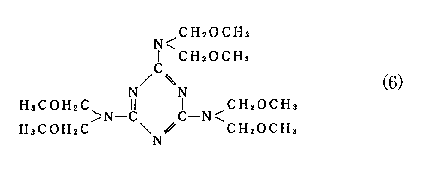
group and/or an alkoxyalkylamino group. Examples of the amino
compound include a melamine-based compound, a urea-based
compound, a benzoguanamine-based compound and a glycoluryl-based
compound.
-
The melamine-based compound is generally known as a
compound having a skeleton in which a nitrogen atom is bound to
a triazine ring. Examples of the melamine-based compound
include melamine, alkylated melamine, methylolated melamine,
alkoxylated methylmelamine and the like. A melamine-based
compound having a total of two or more of a methylol group
and/or an alkoxylated methyl group in the molecule is preferable,
especially methylolated melamine which is obtaind by reacting
melamine and formaldehyde under the basic condition, and
alkoxylated methylmelamine and derivatives thereof are
preferable. Alkoxylated methylmelamine is particularly
preferable in that better storage stability and better
reactivity is given to the curable resin composition.
-
Methylolated melamine and alkoxylated methylmelamine used
as a crosslinkable compound are not particularly limited, but
various resinous materials obtained by the method described in,
for example, the literature "Course of Plastic Material [8]
Urea·Melamine Resin" (published by Nikkankogyoshinbunsha) may be
used.
-
Examples of the urea-based compound include, in addition
to urea, polymethylolated urea and alkoxylated methylurea which
is a derivative of polymethylolated urea, methylolated uron
having an uron ring and alkoxylated methyluron, and the like.
Also in compounds such as urea derivatives, various resinous
materials described in the above-mentioned literature may be
used.
-
An amount of the crosslinkable compound to be formulated
is 70 parts by weight or less, preferably 3 to 50 parts by
weight, more preferably 5 to 30 parts by weight based on 100
parts by weight of the specific fluorine-based polymer. When
the amount of the crosslinkable compound to be used is too small,
the durability of a thin membrane formed of the resulting
curable resin composition is insufficient in some cases. When
the amount exceeds 70 parts by weight, it is difficult to avoid
gelling in a reaction with the specific fluorine-based polymer
and, further, a cured membrane has no low refractive index and
the cured product becomes fragile in some cases.
-
A reaction between a specific fluorine-based polymer and
a crosslinkable compound may be performed, for example, by
adding the crosslinkable compound to a solution obtained by
dissolving the specific fluorine polymer in an organic solvent,
which is heated and stirred for a suitable time to uniformize
the reaction system. A heating temperature for the reaction is
generally in a range of 30 to 150°C, preferably in a range of 50
to 120°C. When the heating temperature is lower than 30°C, the
reaction proceeds extremely slow and, when the temperature is
150°C or higher, a crosslinking reaction between methylol group
or alkoxylated methyl group in the crosslinkable compound is
caused in addition to an end reaction and, thus, a gel is
produced, being not preferable.
-
Progress of the reaction can be confirmed quantitatively
by quantitating a methylol group or an alkoxylated methyl group
with an infrared spectroscopy or the like, or by recovering the
dissolved polymer with a re-precipitating method and measuring
an amount of increase thereof.
-
In the reaction between the specific fluorine-based
polymer and the crosslinkable compound, it is preferable to use
an organic solvent, for example, which is the same organic
solvent as that used in preparing the specific fluorine-based
polymer.
-
In the present invention, a reaction solution containing
a specific fluorine-based polymer and a crosslinkable compound
may be used as a solution of the curable resin composition as it
is, or after various additives are incorporated therein, as
necessary.
<Additive>
-
The above-mentioned curable resin composition may contain
various additives such as various polymers or monomers having a
hydroxyl group, a coloring agent such as a pigment and a dye, a
stabilizing agent such as an anti-aging agent and an ultraviolet
absorbing agent, a thermal acid generator, a photosensitive acid
generator, a surfactant, a solvent, a polymerization inhibitor
and the like in order to improve the coating property of the
curable resin composition and the properties of a thin membrane
after curing, imparting of the photosensitivity to a coated film
and the like.
-
In order to improve the hardness and the durability of a
formed cured membrane, it is particularly preferable that a
thermal acid generator or a photosensitive acid generator is
added and it is particularly preferable that a material which
does not lower the light transmitting properties of the cured
membrane obtained by using the curable resin composition and is
uniformly dissolved in the solution, is selected for use.
<Polymer having hydroxyl group>
-
Examples of a polymer having a hydroxyl group which can
be contained in the curable resin composition include a polymer
obtained by copolymerizing a hydroxyl group-containing
copolymerizable monomer such as hydroxyethyl (meth)acrylate and
the like, a resin having a phenol skeleton which is known as a
novolak resin or a resol resin, and the like.
<Coloring agent such as pigment and dye>
-
Examples of the coloring agent which can be contained in
the above-mentioned curable resin composition include (i)
extender pigments such as alumina white, clay, barium carbonate
and barium sulfate; (ii) inorganic pigments such as zinc white,
lead, chrome yellow, red lead, ultramarine, Prussian blue,
titanium oxide, zinc chromate, red iron oxide, carbon black and
the like; (iii) organic pigments such as brilliant carmine 6B,
permanent red 6B, permanent red 6R, benzidine yellow,
phthalocyanine blue, phthalocyanine green and the like; (iv)
basic dyes such as magenta, rhodamine and the like; (v) direct
dyes such as direct scarlet, direct orange and the like; (vi)
acid dyes such as rhoserine, metanyl yellow and the like; and
others.
<Stabilizing agent such as anti-aging agent and ultraviolet
absorbing agent>
-
As the anti-aging agent or the ultraviolet absorbing
agent which can be contained in the above-mentioned curable
resin composition, the known ones can be used.
-
Examples of the anti-aging agent include di-tert-butylphenol,
pyrogallol, benzoquinone, hydroquinone, methylene
blue, tert-butyl catechol, monobenzylether, methylhydroquinone,
amylquinone, amyloxyhydroquinone, n-butylphenol, phenol,
hydroquinone monopropyl ether, 4,4'-[1-[4-(1-(4-hydroxyphenyl)-1-methylethyl)phenyl]ethylidene]diphenol,
1,1,3-tris(2,5-dimethyl-4-hydroxyphenyl)-3-phenylpropane,
diphenylamines,
phenylenediamines, phenothiazine, mercaptobenzimidazole and the
like.
-
Examples of the ultraviolet absorbing agent include a
salicylic acid-based ultraviolet absorbing agent such as phenyl
salicylate, a benzophenone-based ultraviolet absorbing agent
such as dihydroxybenzophenone and 2-hydroxy-4-methoxybenzophenone,
a benzotriazole-based ultraviolet absorbing
agent, cyanoacrylate-based ultraviolet absorbing agent and the
like which are used as an additive for various plastics.
<Thermal acid generator>
-
The thermal acid generator which can be contained in the
above-mentioned curable resin composition is a material that
improves the heating condition into a milder one when a coating
film of the curable resin composition is heated to cure.
-
Examples of the thermal acid generator include various
aliphatic sulfonic acids and salt thereof, various aliphatic
carboxylic acids such as citric acid, acetic acid and maleic
acid and salts thereof, various aromatic carboxylic acids and
such as benzoic acid and phthalic acid salts thereof,
alkylbenzenesulfonic acid and ammonium salt thereof, various
metal salts, phosphoric ester of phosphoric acid and organic
acid, and the like.
-
An amount of the thermal acid generator to be formulated
is usually 0 to 10 parts by weight, preferably 0.1 to 5 parts by
weight based on 100 parts by weight of the specific fluorine-based
polymer in the curable resin composition. When the amount
of the thermal acid generator becomes large, the storage
stability of the curable resin composition is deteriorated,
being not preferable.
<Photosensitive acid generator>
-
The photosensitive acid generator which can be contained
in the above-mentioned curable resin composition is a material
that gives a photosensitivity to a coating of the curable resin
composition, for example, which allows the coating to be photocured
by irradiating with radiation such as the light or the
like.
-
Example of the photosensitive acid generator include (i)
onium salts such as an iodonium salt, a sulfonium salt, a
phosphonium salt, a diazonium salt, an ammonium salt and a
pyridinium salt; (ii) sulfone compounds such as β-ketoester,
β-sulfonylsulfone and α-diazo compounds thereof; (iii)
sulfonic esters such as alkylsulfonic ester, haloalkylsulfonic
ester, arylsulfonic ester and iminosulfonate; (iv) sulfonimide
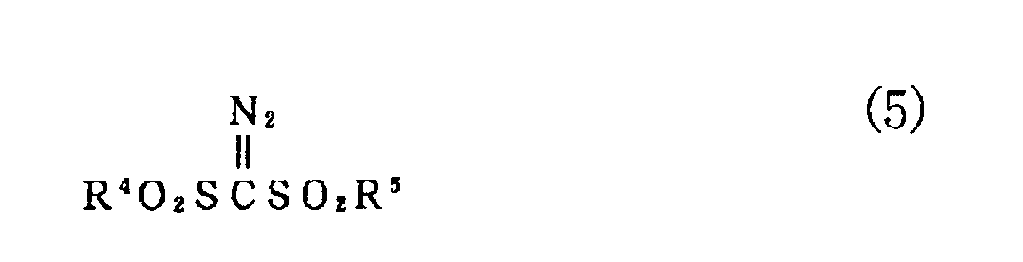
compounds represented by the following general formula (4); (v)
diazomethane compounds represented by the following general
formula (5); and the like.
wherein X denotes a divalent group such as an alkylene group, an
arylene group and an alkoxylene group, and R
3 denotes a
monovalent group such as an alkyl group, an aryl group, a
halogen-substituted alkyl group and a halogen-substituted aryl
group.
wherein R
4 and R
5 may be the same or different and denote a
monovalent group such as an alkyl group, an aryl group, a
halogen-substituted alkyl group and a halogen-substituted aryl
group.
-
The photosensitive acid generators may be used alone or
in combination of two or more, or jointly with the above-mentioned
thermal acid generator.
-
An amount of the photosensitive acid generator to be
formulated is usually 0 to 20 parts by weight, preferably 0.1 to
10 parts by weight based on 100 parts by weight of the specific
fluorine-based polymer in the curable resin composition. When
the amount of the photosensitive acid generator becomes too
large, the strength of the cured membrane is deteriorated, and
the light transmitting properties is lowered, being not
preferable.
<Polymerization inhibitor>
-
Examples of the polymerization inhibitor which can be
contained in the above-mentioned curable resin composition
include pyrogallol, benzoquinone, hydroquinone, methylene blue,
tert-butylcatechol, monobenzyl ether, methylhydroquinone,
amylquinone, amyloxyhydroquinone, n-butylphenol, phenol,
hydroquinone monopropyl ether, 4,4'-[1-[4-(1-(4-hydroxyphenyl)-1-methylethyl)phenyl]ethylidene]diphenol,
1,1,3-tris(2,5-dimethyl-4-hydroxyphenyl)-3-phenylpropane
and the like.
-
The polymerization inhibitor is preferably used in an
amount of 5 parts by weight or less based on 100 parts by weight
of the curable resin composition.
<Surfactant>
-
The surfactant is used in order to improve the coating
property of the curable resin composition. As the surfactant,
the known ones may be used. Specifically, for example, various
anionic surfactants, cationic surfactants or nonionic
surfactants may be contained. It is particularly preferable to
use a fluorine-based surfactant because a cured membrane has an
excellent strength and better optical properties.
-
An amount of the surfactant to be formulated is
preferably 5 parts by weight or less based on 100 parts by
weight of the curable resin composition.
<Solvent>
-
The curable resin composition usually contains a solvent.
And, this curable resin composition is usually obtained as a
solution contained in a solvent used for preparing the specific
fluorine-based polymer, or in a solvent used for reacting the
specific fluorine-based polymer and the crosslinkable compound
and, therefore, the composition itself contains a solvent.
Another solvent may be added and formulated therein in order to
improve the coating property of the curable resin composition or
for other purpose.
-
Examples of the preferable solvent include ketones such
as methyl ethyl ketone, methyl isobutyl ketone and cyclohexanone,
and esters such as ethyl acetate and butyl acetate.
-
Further, in a solution of the curable resin composition,
a solvent which can not dissolve the specific fluorine-based
polymer, for example, a poor solvent such as water, alcohols and
ethers, may be used jointly in such a range that the specific
fluorine-based polymer is not precipitated. Thereby, a solution
containing the specific fluorine-based polymer has a better
retaining property and a preferable coating property in some
cases. Examples of such the poor solvent include ethyl alcohol,
isopropyl alcohol, tert-butyl alcohol and the like.
(Method of forming a coating)
-
It is preferable that the above-mentioned curable resin
composition is coated on at least a transparent part of the
substrate part in the state of a solution. That is, in the case
of a substrate part whose whole part is transparent, the
composition may be coated on the whole face, and in the case of
a substrate part having both a transparent part and a non-transparent
part, the composition may be coated only on the
transparent part or may be coated on the whole face including
the non-transparent part. In addition, the composition may be
coated only on an upper surface (polishing side) of the
substrate part and, further, may be coated also on a lower
surface and, further, may be coated also on a side.
-
As a coating method, the known coating methods can be
used and, various methods such as a dipping method, a coater
method and a printing method can be applied.
-
A thickness of a cured membrane after curing is not
particularly limited, but from the viewpoint of the antifouling
property, it is preferably 100Å or more, more preferably 200 to
20,000Å, most preferably 500 to 5,000Å.
-
It is particularly preferable to give the thermal
hysteresis by heating to a coating of the curable resin
composition to be formed by coating, in order to obtain a cured
membrane having the excellent optical properties and the
durability. Anyway, when allowing to stand at a normal
temperature, a curing reaction proceeds with time and a desired
cured membrane is formed. However, actually, curing by heating
is effective to shorten a required time.
-
In addition, including a thermal acid generator as a
curing catalyst in the curable resin composition leads to
promote a curing reaction. The curing catalyst is not
particularly limited, but the above-mentioned various acids or
salts thereof which have been generally used as a curing agent
for a urethane resin, a melamine resin and the like, can be
utilized. An ammonium salt is particularly preferably used.
-
Although the heating conditions for a curing reaction can
be appropriately selected, it is necessary that a heating
temperature is not higher than a heat resistance limit
temperature of a substrate to be coated.
2. Polishing pad
-
The polishing pad of the present invention is provided
with a window member. Position of the window member is not
particularly limited. Examples include (i) a case wherein a
window member 22 is fitted or inserted in a through hole or a
concave part provided in a substrate for a polishing pad (see
Figs.3 to 11 and 13 to 15), (ii) a case wherein a window member
22 is adhered to a substrate for a polishing pad so as to cover
an opening part of a through hole (see Figs.12 to 17), (iii) a
case wherein a window member 22 is arranged between a substrate
for a polishing pad and a supporting layer to be laminated on
this bottom side (see Figs.16 and 17), and the like. If
necessary, each part may be fixed with an adhesive. In Figs.12
to 15, and 17, No.15 denotes an adhesive layer. In addition, as
shown in Fig.11, at least a bottom (for example, a thin part 11a
etc.) of a substrate for a polishing pad 11 arranged so as to
cover a lower side of the window member needs a transparency to
an extent that the light transmits. Further, as shown in
Figs.16 and 22, at least a bottom [for example, a thin part 2a
(see Fig.16) or a thick part 2b (see Fig.22) etc.] of a
supporting layer 2 arranged so as to cover a lower side of the
window member also needs the light transmitting properties to an
extent that the light transmits. All of the above-mentioned
substrate 11 for the above-mentioned polishing pad and the
supporting layer 2 may be transparent.
(1) Polishing pad having a window member
(Substrate for polishing pad)
-
The "substrate for a polishing pad" can usually retain a
slurry on the surface thereof and, further, can have a polishing
wastage reside thereon transiently. A whole shape of the
polishing pad is not particularly limited, but may be circle
(disc-like etc.), polygon (square etc.), belt shape, and the
like. In the present invention, disc-like and belt shapes are
particularly preferable. A size thereof is not also
particularly limited. For example, in the case of a disc-like
shape, a diameter may be 500 to 900mm and, in the case of a belt
shape (endless), an entire length may be 1,500 to 3,000mm, a
lateral width may be 200 to 500mm.
-
In addition, transmitting properties of the substrate
having a window member does not need to consider.
-
Further, it is preferable that a fine hole (hereinafter,
referred to as "pore") or a groove is formed on the surface of
the substrate for a polishing pad at least until polishing, in
order to retain a slurry during polishing and have a polishing
wastage reside thereon transiently as described above. That is,
a pore and/or a groove may be formed on a substrate for a
polishing pad in advance (for example, a foam etc.), or a pore
and/or a groove may be formed thereon by eliminating particles
and the like off during polishing. As the latter, a matrix
material in which a water-soluble material (particle shape,
linear shape etc.) having a prescribed shape is dispersed, can
be used as the substrate for a polishing pad. In such the
substrate for a polishing pad, a pore and/or a groove is formed
on a part where a water-soluble material is eliminated off or
dissolved by contact with an aqueous medium.
-
A material constituting a substrate for a polishing pad
is not particularly limited, but various materials can be used,
and it is particularly preferable that an organic material is
used because it is easily molded into a prescribed shape and
nature and can give the suitable elasticity. As this organic
material, various materials which can be applied as the above-mentioned
substrate part material constituting a window member
and the like, can be used. Examples thereof include curable
resins such as 1,2-polybutadiene, a urethane resin, an epoxy
resin, an acrylic resin, an unsaturated polyester resin and a
vinyl ester resin, and crosslinked rubbers obtained by
crosslinking a butadiene rubber, an isoprene rubber, an acrylic
rubber, an acrylonitrile-butadiene rubber, a styrene-butadiene
rubber, an ethylene-propylene rubber, a silicone rubber, a
fluorine rubber and a styrene-isoprene rubber. In particular, a
substrate for a polishing pad having a belt shape needs the
flexibility like a window member. As a material in this case, a
polyurethane resin and crosslinked 1,2-polybutadiene are
preferable. A material constituting the substrate for a
polishing pad and a substrate part material may be the same or
different.
-
In addition, when the above-mentioned water-soluble
material which is eliminated off during polishing is dispersed
for the purpose of forming a pore and/or a groove on the surface
of the substrate for a polishing pad, an organic water-soluble
material and an inorganic water-soluble material can be used as
a water-soluble material. Examples of the organic water-soluble
material include dextrin, cyclodextrin, mannit, sugars (lactose
etc.), celluloses (hydroxypropylcellulose, methylcellulose etc.),
starch, protein, polyvinyl alcohol, polyvinyl pyrrolidone,
polyacrylic acid, polyethylene oxide, water-soluble
photosensitive resin, sulfonated polyisoprene, sulfonated
polyisoprene copolymer and the like. Further, examples of the
inorganic water-soluble material include potassium acetate,
potassium nitrate, potassium carbonate, potassium
hydrogencarbonate, potassium chloride, potassium bromide,
potassium phosphate, magnesium nitrate and the like.
-
The "through hole" penetrates through a substrate for a
polishing pad from a surface to a back and is provided for
fitting with a window member. The through hole may be
completely filled with a window member (Figs.4 and 6 etc.), or a
part thereof may be filled with a window member (Figs.5 and 7
etc.). A shape of the through hole is not particularly limited.
For example, referring to Figs.18 to 26, a planar shape of an
opening part thereof may be circle (see Fig.23), ellipse (see
Fig.25), track shape, square shape in which four corners are
beveled, fan, polygon (regular square; see Fig.24, general
trapezoid (see Fig.18) and general long rectangle (groove-like);
(see Figs.26 and 20) and ring-like (see Fig.21) and the like.
In addition, a cross-sectional shape of the through hole may be,
for example, T letter shape, reverse T letter shape, square or
other shape (see Figs.3 to 10, wherein an upper side is a
polishing side in each figure). Among them, T letter shape is
particularly preferable.
-
A size of the through hole is not particularly limited.
Usually, when an opening part is circle, it is preferable that a
diameter is 20mm or more (usually, 2/3 or less a radius of a
polishing pad). In the case of an annular through hole, it is
preferable that a width thereof is 20mm or more (usually, 2/3 or
less a radius of a polishing pad). In the case of square, it is
preferable that a longitudinal size is 30mm or more (usually,
2/3 or less a radius of a polishing pad) and a transverse size
is 10mm or more (usually, 2/3 or less a radius of a polishing
pad). When each through hole becomes smaller than the above-mentioned
size, it becomes difficult to assuredly transmit the
light used for endpoint detection in some cases.
-
Further, the number of through holes is not particularly
limited, but may be one, or two or more. Position thereof is
not also particularly limited. For example, referring to
Figs.12 to 15, when an entire shape is disc-like, in order to
provide one through hole, it can be arranged as shown in Fig.12
(planar rectangular) or Fig.15 (ring-like). In order to provide
a plurality of through holes, they may be arranged
concentrically (Fig.13; planar rectangular shape, Fig.14; planar
long rectangular (groove-like)) or in other format. In addition,
referring to Fig.17, in the case of a belt type, a plurality of
through holes may be arrayed (linear arrangement, irrespective
of an end side or a central side) or arranged in other format
(zigzag-like, arrangement in which a group of a plurality of
holes is repeated in an array). This array may be on an end
side as shown in Fig.17, or may be on a central side.
-
Further, the substrate for a polishing pad may have a
concave part having a certain depth. In this case, a substrate
has a thin part 11a under the concave part (see Fig.11). This
concave part in which the thin part is to be formed is a place
where a window member is inserted. A planar shape and a
longitudinal cross-sectional shape of the concave part are not
particularly limited, but may be the same as the planar shape
(see Figs.12 to 19) and the longitudinal cross-sectional shape
of the above-mentioned through hole, for example. An upper side
(an open side of the concave part) in these figures is a side to
be polished. When a material constituting the substrate for a
polishing pad has the light transmitting properties, by
providing a thin part, the light transmitting properties at the
thin part can be further enhanced. Therefore, even when it is
difficult to transmit the light having the sufficient strength
for detecting a polishing endpoint through parts other than this
thin part, the sufficient strength of the light for endpoint
detection can be maintained at a thin part.
-
Further, the number of concave parts is not particularly
limited, but may be one, or two or more. In addition, position
thereof is not particularly limited, but may be arranged as in
the above-mentioned through hole (see Figs.12 to 15, Figs.17 to
19).
-
A thickness of the thin part is not particularly limited.
Usually, it is preferable that a thinnest thickness of the thin
part is preferably 0.1mm or more, more preferably 0.3mm or more,
but usually 3mm or less. When the thickness is less than 0.1mm,
there is a tendency that it becomes difficult to obtain a
sufficient mechanical strength at this part. In addition, a
size of the thin part is not particularly limited. For example,
in the case of circle, it is preferable that a diameter is 20mm
or more. In the case of an annular shape, it is preferable that
a width thereof is 20mm or more. In the case of rectangle, it
is preferable that a longitudinal size is 30mm or more and a
transverse size is 10mm or more.
(Window member)
-
The window member explained in the above-mentioned item 1.
is applied to this window member. And, a planar shape of a
polishing side of the window member usually depends on a shape
of a through hole or that of a concave part formed in a
polishing pad. Usually, a shape of a window member is the same
as that of a through hole or a concave part, and may be circle,
polygon or the like. In addition, a cross-sectional shape
thereof is particularly limited, but may be usually a shape in
which at least a part thereof is fitted or inserted into a
through hole or a concave part, or a shape in which at least a
part thereof is adhered to an opening part of a through hole.
For example, cross-sectional shapes shown in Fig.3 to Fig.17 may
be used. The window member may be fitted in the above-mentioned
substrate for a polishing pad and, at the same time, may be
adhered by an adhesive or the like. The adhesive is not
particularly limited to use.
-
The window member is wholly fitted or inserted in the
through hole (see Figs.3 to 10). In addition, a convex part of
the window member having a longitudinal cross-section of a
reverse T letter shape may be fitted, and a plate part (bottom
part) may be adhered to a substrate for a polishing pad so as to
protrude from the through hole (see Fig.13). Alternatively, the
window member may be inserted so that there is a gap between the
window member and the through hole (see Fig.14). Further, an
upper level of the window member to be inserted may be lower
than an upper level of the substrate for a polishing pad,
forming a difference in level on the surface of a substrate for
a polishing pad (see Fig. 15). In this case, the above-mentioned
gap may be present or absent.
-
In addition, the window member may be adhered to the
substrate for a polishing pad so as to cover an opening part of
a through hole (see Figs.12 to 17). In this case, a plate-like
or sheet-like window member may be fixed by adhering to a lower
surface of the substrate for a polishing pad (see Fig.12). In
this case, a vacancy part or the like for inserting the window
member may be provided on a lower side of the substrate for a
polishing pad and the window member may be fixed by connecting
with the vacancy part. Further, a convex part of the window
member having a longitudinal cross-section of a reverse T letter
shape may be fitted or inserted in the through hole and, at the
same time, the plane part (bottom part) may be adhered to a
substrate for a polishing pad (see Figs.13 to 15). Any kind of
adhesives is available in this case, but it is convenient to use
a both sides coated adhesive tape.
-
The number of window members is not particularly limited,
but is corresponding to the number of through holes or concave
parts because a window member is fitted or inserted in a through
hole or concave part. That is, the number may be one, two or
more. In addition, position of the window member is
corresponding to the shape of through hole or concave part as
described above. For example, referring to Figs.18 to 21, when
a whole shape is disc-like, in order to provide one window
member, it can be arranged as in Fig.18 (in the case of a planar
rectangular window member) or Fig.21 (in the case of ring-like
window member). When a plurality of window members are provided,
they can be arranged concentrically (Fig.19; planar rectangular
window member, Fig.20; planar long square (groove-like) window
member) or in another format. In addition, in the case of a
belt type, referring to Figs.23 to 26, a plurality of window
members (Fig.25 is a view in which a plurality of window members
are arranged at a large interval) may be arrayed (linear
arrangement irrespective of an end side or a central side) or
arranged in another format (zigzag-like, a group of a plurality
of window members is repeated in an array manner). This array
may be on an end side as in Figs.23 to 26, or on a central side.
-
In this case, a thickness of the window member is usually
the same as that of the substrate for a polishing pad (see Fig.
8 etc.), but not limited, and the window member may be thinned.
Thinning means making a thickness of a window member thinner
than a maximum thickness of a substrate for a polishing pad (for
example, Fig.5, Figs 7 to 9, etc.) and forming a part of a
window member through which the light transmits thinner in the
window member itself (for example, Fig.10 etc.).
-
When the light transmits through a window member, an
intensity of the light is reduced in proportion to square of the
thickness of the window member or the like through which the
light transmits. Therefore, by thinning the window member or
the like, the light transmitting properties can be dramatically
improved. For example, in a polishing pad used for polishing in
which endpoint detection is performed optically, even when it is
difficult to obtain the sufficient intensity of the light for
detecting an endpoint in the case of a window member having the
same thickness as that of other parts of the polishing pad, by
thinning a window member, a sufficient intensity of the light
for endpoint detection can be ensured. It is preferable that a
thickness of the thinned window member is 0.1mm or more, more
preferably 0.3mm or more, usually 3mm or less. When the
thickness is less than 0.1mm, there is a tendency that it
becomes difficult to sufficiently maintain the mechanical
strength of the window member.
-
Although a concave part 14 in Fig.5 and a concave part 13
in Fig.10 may be formed on a surface or a back of the polishing
pad, respectively. By formation on the back, the window member
or the like can be thinned without influencing on the polishing
performance.
-
Further, a window member may be interposed between
substrates which are divided into at least two parts, for
example, substrates which are divided into two parts (see Fig.
27) and may be fixed by adhesion. In this case, a belt-like
window member is used as shown in Fig.2. In addition, as shown
in Fig.27, it is usually applied to a belt-like polishing pad.
A position of the window member to be arranged may be on an end,
or a center.
-
It is preferable that the transmitting properties of the
window member is as follows, that is, in the case where a
thickness of the window member is 2mm, a light transmittance at
a wavelength between 100 and 3,000nm is 0.1% or more, or an
integrated transmittance in a proper wavelength range between
100 and 3,000nm is 0.1% or more. This transmittance or
integrated transmittance is preferably 1% or more, more
preferably 2% or more. However, this transmittance or
integrated transmittance may not be higher than that as required.
Usually, it may be 50% or less, further 30% or less,
particularly 20% or less.
-
Further, the whole polishing pad of the present invention
may contain, in addition to the window member, an abrasive, an
oxidizing agent, a hydroxide of an alkali metal, an acid, a pH
adjusting agent, a surfactant, a scratch inhibitor and the like
in such a range that the transmitting properties can be
maintained.
-
Besides, further, various additives such as a filler, a
softening agent, an antioxidant, an ultraviolet absorbing agent,
an antistatic agent, a lubricant, a plasticizer and the like may
be contained therein. In particular, as the filler, materials
which increase the rigidity such as calcium carbonate, magnesium
carbonate, talc, clay and the like, and materials having the
polishing effects such as silica, alumina, ceria, zirconia,
titania, manganese dioxide, dimanganese trioxide, barium
carbonate and the like may be used.
(2) Polishing pad comprising a multi-layered body for polishing
with a supporting layer on a back
-
A polishing pad of the present invention may be provided
with a supporting layer 2 on a back of a substrate (see Figs.16,
17 and 22).
-
The "supporting layer" is a layer to be laminated on a
back which is an opposite side relative to a polishing side of
the polishing pad. In this case, the whole bottom including a
substrate for a polishing pad and a window member may be covered
(see Fig.22). Or only a substrate for a polishing pad except
for a window member may be covered. In the case a supporting
layer comprised of a material having the light transmitting
properties equal to or superior over that of the window member
is used, the light transmitting properties in the multi-layered
body for polishing can be maintained. In this case, a vacancy
part may be or may not be formed on a part corresponding to a
window member. In addition, when a support having no light
transmitting properties is used, notching a part through which
the light transmits makes light transmitting properties of the
multi-layered body for polishing maintained.
-
Further, in the case a supporting layer is laminated on a
bottom of a substrate for a polishing pad, when a window member
is sheet-like, for example, the window member may be held
between the substrate for a polishing pad and the supporting
layer (see Figs.16 to 17). As shown in Fig.17, a part (for
example, both ends etc.) of the window member may be inserted.
This case includes (i) a window member is simply held between a
substrate for a polishing pad and a supporting layer (a vacancy
part or the like shown below is formed nowhere), (ii) a concave
part or a vacancy part is provided on a supporting layer so as
to insert a window member therein, whereby, a window member is
held therein, and (iii) a vacancy part or the like for inserting
a window member is provided on a lower side of a substrate for a
polishing pad, whereby, a window member is held therein. Fig.
17 is conveniently an illustration including an aspect of the
(i) and that of (ii).
-
A shape of the supporting layer is not particularly
limited, but a planar shape may be, for example, polygon (square
etc.), a circle and the like. The supporting layer may also be
a thin plate. The supporting layer usually has the same planar
shape as that of a polishing pad (when a part for maintaining
light transmitting properties by a vacancy part is given, the
part is excluded).
-
A material constituting the supporting layer is not
particularly limited, but a variety of materials may be used.
In particular, it is preferable that an organic material is used
because it is easily molded into a prescribed shape and nature
and also it can give the suitable elasticity. As this organic
material, materials which are applied to a substrate part
material constituting the above-mentioned window member can be
used, provided that, a material constituting the above-mentioned
supporting layer and a material constituting the substrate part
material of the above-mentioned window member may be the same or
different.
-
In addition, a hardness of the supporting layer is not
particularly limited, but the supporting layer is preferably
softer than a substrate for a polishing pad. Whereby, a
polishing pad as a whole has a sufficient flexibility, and it
can be appropriately adapted to the irregularity of the surface
to be polished. In particular, in the case of using a belt-like
polishing pad, one having a flexibility is preferable.
-
In addition, the number of the supporting layers is not
limited. The supporting layer may be one layer, or a laminate
of two or more layers. Further, in the case where two or more
supporting layers are laminated, respective layers may be
composed of the same component, or may be composed of the
different component.
-
The present polishing pads have light transmitting
properties due to provision of a window member and enable the
light to transmit through the window member. For this reason,
in polishing using the present polishing pads, observing the
polishing situations with an optical method is possible. That
is, for example, the polishing pads are suitable for polishing a
wafer using an optical endpoint detecting apparatus.
(Method of polishing a semiconductor wafer)
-
Polishing a semiconductor wafer can be carried out using
a polishing pad and detecting a polishing endpoint of the
semiconductor wafer using an optical endpoint detector.
-
The "optical endpoint detector" is an apparatus which can
observe the polishing situations with the light reflected from
the surface of a material to be polished through a transparent
window member or a chemical mechanical polishing window member
and a polishing endpoint of a side to be polished, and can
detect a polishing endpoint. Other measuring principles are not
particularly limited.
-
According to this method of polishing a semiconductor
wafer, polishing can be performed while always observing a
polishing endpoint, for example, (i) by arranging window members
on a disc center and concentrically or by using a ring-like
window member where the polishing pad or the polishing multi-layered
body is disc-like, (ii) by arraying window members
parallel in the case of a belt-like polishing pad, or the like.
Therefore, polishing can be finished assuredly at an optimal
polishing endpoint.
-
In the case of polishing a semiconductor wafer, for
example, a polishing apparatus as shown in Fig.22 or Fig.28 may
be used. That is, such the polishing apparatus is an apparatus
provided with a rotatable surface plate 2 or a belt-like
polishing pad 1, a pressure head 3 which can rotate and move in
a longitudinal direction and a transverse direction, a slurry
supplying part 5 which can add a slurry dropwise on the surface
plate 2 at a certain amount per unit time, and an optical
endpoint detecting part 6 which is arranged under the surface
plate 2 or the belt-like polishing pad 1.
-
The above-mentioned "slurry" means an aqueous dispersion
containing at least an abrasive. However, the slurry or only an
aqueous medium without abrasive may be supplied from the outside
during polishing. When only an aqueous medium is supplied, for
example, the slurry can be formed by mixing an abrasive released
from the interior of the polishing pad and the aqueous medium
during polishing.
-
In this polishing apparatus, a disc-like or another
shaped polishing pad 1 is fixed on a surface plate (Fig.22), or
a belt-like polishing pad is transferred by a roll (Fig.28) and,
on the other hand, a semiconductor wafer 4 is fixed on a lower
end of the press head 3, and the semiconductor wafer 4 is
abutted against a polishing pad by pushing at a prescribed
pressure. And, polishing is performed by sliding a
semiconductor wafer and a polishing pad by rotating a surface
plate or a belt-like polishing pad and a pressure head while a
prescribed amount of the slurry is added dropwise on the
polishing pad or the like from a slurry supplying part.
-
Upon this polishing, the endpoint detecting light R1
having a prescribed wavelength or a wavelength region is
irradiated to the surface to be polished of the semiconductor
wafer through the window member 12 from a lower side of the
surface plate 2(the endpoint detecting light or a belt-like
polishing pad can transmit the surface plate when the surface
plate itself has the light transmitting properties or a vacancy
part is formed at a part of surface plate), from an optical
endpoint detecting part 6. Then, the reflected light R2 which
is this endpoint detective light reflected on the surface of the
semiconductor wafer to be polished is captured by the optical
endpoint detecting part 6, and polishing can be performed while
observing the situations of the surface to be polished from this
reflected light.
Brief description of the drawings
-
- Figure 1 is a longitudinal cross-section of a window
member for chemical mechanical polishing.
- Figure 2 is a perspective of a part of a belt-like window
member for chemical mechanical polishing as another aspect.
- Figure 3 is a longitudinal cross-section of a part of a
polishing pad in which a window member is inserted fittingly in
a substrate for a polishing pad.
- Figure 4 is a longitudinal cross-section of a part of a
polishing pad as another aspect in which a window member is
inserted fittingly in a substrate for a polishing pad.
- Figure 5 is a longitudinal cross-section of a part of a
polishing pad as another aspect in which a window member is
inserted fittingly in a substrate for a polishing pad.
- Figure 6 is a longitudinal cross-section of a part of a
polishing pad as another aspect in which a window member is
inserted fittingly in a substrate for a polishing pad.
- Figure 7 is a longitudinal cross-section of a part of a
polishing pad as another aspect in which a window member is
inserted fittingly in a substrate for a polishing pad.
- Figure 8 is a longitudinal cross-section of a part of a
polishing pad as another aspect in which a window member is
inserted fittingly in a substrate for a polishing pad.
- Figure 9 is a longitudinal cross-section of a part of a
polishing pad as another aspect in which a window member is
inserted fittingly in a substrate for a polishing pad.
- Figure 10 is a longitudinal cross-section of a part of a
polishing pad as another aspect in which a window member is
inserted fittingly in a substrate for a polishing pad.
- Figure 11 is a longitudinal cross-section of a part of a
polishing pad in which a window member is inserted fittingly in
a concave part of a substrate for a polishing pad.
- Figure 12 is a longitudinal cross-section of a part of a
polishing pad in which a window member is adhered to a substrate
for a polishing pad so as to cover an opening part of a through
hole.
- Figure 13 is a longitudinal cross-section of a part of a
polishing pad in which a window member is inserted fittingly in
a through hole, and is adhered to a substrate for a polishing
pad so as to cover an opening part.
- Figure 14 is a longitudinal cross-section of a part of a
polishing pad in which a window member is inserted such that
there is a gap left in a through hole.
- Figure 15 is a longitudinal cross-section of a part of a
polishing pad in which an upper level of an inserted window
member is lower than an upper level of a substrate for a
polishing pad.
- Figure 16 is a longitudinal cross-section of a part of a
polishing pad in which a sheet-like (or plate-like) window
member is adhered to a substrate for a polishing pad so as to
cover an opening part of a through hole, and a supporting layer
is laminated on a back.
- Figure 17 is a longitudinal cross-section of a polishing
pad in which a sheet-like (or plate-like) window member is
adhered to a substrate for a polishing pad so as to cover an
opening part of a through hole and, at the same time, both ends
of a window member are disposed between a substrate for a
polishing pad and a supporting layer to be laminated on a back
thereof.
- Figure 18 is a plane view of one example of a disc-like
polishing pad.
- Figure 19 is a plane view of another example of a disc-like
polishing pad.
- Figure 20 is a plane view of another example of a disc-like
polishing pad.
- Figure 21 is a plane view of another example of a disc-like
polishing pad.
- Figure 22 is a schematic view illustrating a polishing
apparatus using a polishing pad.
- Figure 23 is a plane view of a part of a belt-like
polishing pad provided with a circular window member.
- Figure 24 is a plane view of a part of another example of
a belt-like polishing pad provided with a square window member.
- Figure 25 is a plane view of a part of another example of
a belt-like polishing pad provided with an elliptic window
member.
- Figure 26 is a plane view of a part of another example of
a belt-like polishing pad provided with a long square window
member.
- Figure 27 is a plane view of a part of another example of
a belt-like polishing pad.
- Figure 28 is a schematic view illustrating a polishing
apparatus using a belt-like polishing pad.
- Figure 29 is a chart illustrating an infrared absorbing
spectrum of a reaction product of fluorine-based polymer A1 and
a crosslinkable compound in Example.
-
Explanation of reference character
-
1; polishing pad, 11; substrate for polishing pad, 11a;
thin part, 12; window member for chemical mechanical polishing,
12a; substrate part, 12b; antifouling resin layer, 13 & 14;
concave part, 15; adhesive layer, 2; supporting layer, 3;
pressure head, 4; semiconductor wafer, 5; slurry supplying part,
6; optical endpoint detecting part, R1; endpoint detecting light,
R2; reflected light.
Description of the preferred Embodiments
-
The present invention will be explained by way of
Examples below but is not limited by them. In the following
explanation, "part" and "%" denote part by weight and % by
weight, respectively, unless otherwise indicated.
1. Formation and evaluation of an antifouling resin layer used
in a window member for chemical mechanical polishing
<Preparation of a specific fluorine-based polymer>
Preparation example 1
-
A stainless autoclave equipped with an electromagnetic
stirrer whose inner volume is 2.0 liters was sufficiently
replaced with a nitrogen gas, 500g of ethyl acetate as a solvent,
53.2g of perfluoro(propyl vinyl ether) (FPVE) as the component
(a), 48.7g of ethyl vinyl ether (EVE) and 26.4g of hydroxybutyl
vinyl ether (HBVE) as the component (b), 20.0g of nonionic
reactive emulsifier (manufactured by Asahidenka Co. Ltd., trade
name; "Adeka REASOAP NE-30") as the component (d), 3.0g of azo
group-containing polydimethylsiloxane (manufactured by Wako Pure
Chemical Industries, Co. Ltd., trade name; "VPS-1001") as the
component (c) and 1.0g of lauroyl peroxide (LPO) as a
polymerization initiator were placed therein, which was cooled
with a dry ice-methanol-based freezing medium to -50°C, and
oxygen in the system was removed again with a nitrogen gas.
-
Next, 120g of hexafluoropropylene (HFP) as the component
(a) was added therein, and heating was started. The pressure
when a temperature in the autoclave reached 60°C was 6.1kgf/cm2.
Thereafter, a reaction was carried out continued at 60°C for 20
hours while stirring. After the pressure was reduced to
2.5kgf/cm2, the autoclave was cooled with water to stop the
reaction. And the reaction was made to reach room temperature,
the unreacted monomer was released to open the autoclave, to
obtain a polymer solution. The resulting polymer solution was
discharged into methanol to precipitate a polymer, which was
washed with methanol, and dried in vacuum at 50°C to obtain 221g
of a fluorine-based copolymer A1. A placed amount of a monomer
for obtaining the fluorine-based copolymer A1, a yield, a
polymerization conversion and a solid content are shown in Table
1.
-
The fluorine-based copolymer A1 was dissolved in
tetrahydrofuran (THF) to prepare a 0.5% solution, which was used
to obtain a number-average molecular weight reduced to
polystyrene by gel permeation chromatography, and it was found
to be 55,000.
-
Further, a glass transition temperature (Tg) by a
differential scanning calorymetry (DSC) and a fluorine content
by an alizarin complexon method were measured, respectively.
And content of HBVE was calculated from a hydroxide value by an
acetylation method using acetic anhydride. In addition, NMR
analyses of 1H-NMR, 13C-NMR, and elementary analysis were
performed and, further, a fluorine content, a hydroxide value
and inorganic silica content from the remaining weight after
calcination at 600°C were measured. From these results,
contents of monomer components constituting the fluorine-based
copolymer A1 were obtained. The results are shown in Table 2.
Preparation example 2 and Comparative preparation example
1
-
The fluorine-based copolymer A2 and the Comparative
copolymer B1 were prepared according to the same manner as that
for Preparation example 1 except that a kind and an amount to be
placed of each monomer were changed as shown in Table 1. In
addition, contents of monomer components constituting the
copolymers and properties of copolymers are shown in Table 2.
| Component | Monomer (g) | Preparation example | Comparative preparation example |
| | | 1 | 2 | 1 |
| | | A1 | A2 | B1 |
| (a) | HFP | 120.0 |
| CTFE | | 146.6 |
| FPVE | 53.2 |
| (b) | HBVE | 26.4 | 34.5 | 213.3 |
| EVE | 48.7 | | 56.7 |
| Iso―BVE | | 19.7 |
| CHVE | | 72.3 |
| (d) | NE―30 | 20.0 |
| (c) | VPS―1001 | 3.0 | 3.0 |
| Polymerization Initiator LPO | 1.0 | 1.0 |
| Yield (g) | 221 | 175 | 257 |
| Conversion (%) | 81 | 64 | 97 |
| Solid content (%) | 28.6 | 22.6 | 33.2 |
| Component | Monomer (mol%) | Preparation example | Comparative preparation example |
| | | 1 | 2 | 1 |
| | | A1 | A2 | B1 |
| (a) | HFP | 41.1 |
| CTFE | | 52.1 |
| FPVE | 10.0 |
| (b) | HBVE | 11.8 | 12.4 | 69.8 |
| EVE | 33.9 | | 30.2 |
| Iso―BVE | | 8.8 |
| CHVE | | 26.7 |
| (d) | NE-30 | 0.8 |
| (c) | Structure unit by the component (mol%) | 2.4 | 2.6 | 0 |
| Number-average molecular weight | 55,000 | 24,000 | 23,000 |
| Fluorine content (%) | 49.8 | 26.0 | 0 |
-
Abbreviations in Tables denote the following compound.
- [i] Component (a)
- HFP: hexafluoropropylene
- CTFE: chlorotrifluoroethylene
- FPVE: perfluoro(propyl vinyl ether).
- [ii] Component (b)
- EVE: ethyl vinyl ether
- iso-BVE: isobutyl vinyl ether
- CHVE: cyclohexyl vinyl ether
- VAc: vinyl acetate
- VPi: vinyl pivalate
- VeoVa10: vinyl versatate
- HBVE: hydroxybutyl vinyl ether
- GVE: glycidyl vinyl ether.
- [iii] Component (c)
VPS-1001: azo group-containing polydimethylsiloxane
represented by the above-mentioned general formula (2), wherein
y = 120 to 150, z = 7 to 10, having a number-average molecular
weight of 70,000 to 90,000 and a molecular weight of a
polysiloxane segment of about 5,000.
- [iv] Component (d)
NE-30: nonionic reactive emulsifier "NE-30" represented by
the above-mentioned general formula (3) wherein n = 9, m = 1,
and s = 30.
-
<Production of a curable resin composition solutions a1, a2 and
b1>
-
As shown in Table 3, 100g of the specific fluorine-based
polymer A1 obtained in Preparation example 1 and 30g of
methoxylated methylmelanine (manufactured by Mitsui Cytec Co.
Ltd., trade name; "Cymel 303") which is self-condensated the
compound represented by the following formula (6) to obtain an
average 1.7-mer as a crosslinkable compound were dissolved in
900g of methyl isobutyl ketone (MIBK) as a solvent, and they
were reacted at 100°C for 5 hours under stirring. After the
reaction, the reaction system was cooled to room temperature to
obtain a solution containing a crosslinked polymer which is a
reaction product between the specific fluorine-based polymer and
the crosslinkable compound.
-
Then, this solution was gradually poured into a large
amount of cold methanol while stirring to precipitate the
crosslinked polymer. Further, the resulting polymer was
dissolved in MIBK, which was subjected to the precipitation
using cold methanol again.
-
The resulting polymer was dried by vacuum drying. A
chart of the infrared absorbing spectrum of this crosslinked
polymer after drying is shown in Fig.29.
-
Then, 100g of the above-mentioned crosslinked polymer and
2g of p-toluenesulfonic acid which is a curing catalyst were
added to 900g of MIBK to dissolve them, to produce a curable
resin composition solution a1. This solution had the solid
content of 10% and the viscosity of 30cps or lower.
-
Further, a crosslinked polymer was prepared according to
the same manner as that described above except that the specific
fluorine-based polymer and the crosslinkable compound in the
above-mentioned curable resin composition solution a1 were
exchanged with those shown in Table 3. And a curing catalyst
shown in Table 3 was added to the resulting polymer to produce
curable resin composition solutions a2 and b1. In Table 3, the
amount of the curing catalyst indicates an amount to be added
(g) relative to 100g of the crosslinked polymer.
| | Production example | Comparative production example |
| | 1 | 2 | 1 |
| Curable resin composition solution | a1 | a2 | b1 |
| Crosslinked polymer | Copolymer | A1 | A2 | B1 |
| Solid content (g) | 100 | 100 | 100 |
| Cymel 303 (g) | 30 | 20 | 20 |
| Curing catalyst | p-toluenesulfonic acid (g) | 2 | 2 | 2 |
<Formation and evaluation of a window member provided with a
cured membrane obtained from a curable resin composition>
Example 1 to 4 and Comparative example 1 to 4
-
Curable resin composition solutions a1, a2 and b1
produced described above were coated on each resin substrate
(200µm-thickness film) shown in Table 4 at a pulling up rate of
500mm/min by a dip coating method, respectively. And which were
heated to cure at 120°C for 1 hour to form cured coatings.
-
Films on which the cured coatings had been formed were
soaked in a slurry for chemical mechanical polishing containing
a copper complex at 25°C for 1 hour, respectively. And staining
properties (degree of staining) by adhesion of the copper
complex to the films were evaluated. Comparative Examples 2 to
4 are examples that cured coating is not formed. The slurry for
chemical mechanical polishing and a stain evaluating method used
are as follows.
- (1) Slurry for chemical mechanical polishing: Prepared by
dispersing 2% of fumed silica (Nippon Aerosil Co. Ltd., trade
name; "Aerosil #901"), 1% of quinaldinic acid and 1% of hydrogen
peroxide in ion-exchanged water.
- (2) Stain evaluating method: In order to mimicly reproduce a
copper complex produced in actual chemical mechanical polishing,
0.5% solution of copper sulfate was added to the above-mentioned
slurry for chemical mechanical polishing to form a copper
complex. After the film on which a cured membrane was formed
was soaked in the mixed solution, the film was washed with water,
and a degree of staining of the surface was determined by the
following criteria visually. These results are shown in Table 4.
- 5: No observation of staining.
- 4: A part of the film was slightly stained.
- 3: About 1/2 film was stained.
- 2: The whole film was slightly stained.
- 1: The whole film was stained and no light transmitting
properties were observed.
-
-
Further, according to the following method, an anti-scratching
test (Examples 1 to 4 and Comparative Example 1) was
carried out. That is, each curable resin composition solution
shown in the Table 4 was diluted with butanol to prepare a
varnish having the solid content of 4%. This varnish was coated
on a transparent polyurethane film having a thickness of 0.2mm
at a pulling up rate of 500mm/min. by a dip coating method, and
the resulting coating was heated at 120°C for 1 hour to form a
cured membrane. The thickness of the cured membrane measured by
an ellipsometer was 1,140Å. A prescribed resin sheet on which a
cured membrane was formed (referred to as "sample") was made.
-
Regarding the above-mentioned respective samples, an
anti-scratching test was performed in order to evaluate the
adherability of the cured membrane to the polyurethane film and
the strength of the cured membrane. That is, a surface of the
cured membrane was abraded repeatedly 25 times under a load of 1
kg/cm2 using a wiping paper (manufactured by Jujo Kimbery Co.
Ltd., trade name; "Kimwipe"), and the presence or the absence of
a flaw on the surface of the cured membrane was checked visually.
And, no observation of a peeling and a flaw was evaluated as "○
", and a peeling on a part of a cured membrane, or a linear flaw
on the surface of the cured membrane was evaluated as "×". In
addition, transmittances of the samples after the evaluation of
staining were measured in the range of 400 to 800nm with
ultraviolet spectroscopy (manufactured by Hitachi Co. Ltd.,
type; "U-2010") and average data were calculated. These results
are also shown in Table 4.
-
Based on the results in Table 4, it can be seen that
resin sheets using cured resin compositions according to
Examples 1 to 4 have excellent antifouling properties. To the
contrary, in the case of Comparative Example 1 in which a cured
membrane was formed using a polymer containing no fluorine, and
Comparative Examples 2 to 4 in which cured membranes were not
formed, it can be seen that the antifouling property improving
effects are hardly perceived. And it can be seen that the anti-scratching
is also excellent in Examples 1 to 4 as compared with
Comparative Example 1.
2. Production and evaluation of a belt-type polishing pad
[1] Production of a polishing pad
-
First, a polyurethane resin part which is to constitute a
substrate part 12a for a window member is prepared. This part
has a sheet shape whose length is 65mm, width 50mm and height
0.3mm (see Fig.12). On this part was formed a cured membrane
(antifouling resin layer, thickness; about 1,150Å) 12b using the
curable resin composition solution a1 obtained in the above
Production example 1 by the dip coating method as described
above, to produce a window member 12 (see Fig.12).
-
On the other hand, a belt comprised of polyurethane foam
(total length; about 2,000mm, transverse width; about 350mm,
thickness; about 3mm) was prepared, and two through holes (long
diameter; about 3.2mm, short diameter; about 2.5mm) were
provided at an interval of about 1,000mm. And, the above-mentioned
window member 12 was fixed by adhering to a bottom of
a substrate 11 for a polishing pad with adhesives so as to cover
opening parts of these through holes. Thereby, a polishing pad
1 used in this test was produced (see Fig.12).
-
In addition, 100 parts of 1,2-polybutadiene (manufactured
by JSR Corp., trade name; "JSR RB840") and 100 parts of β-cyclodextrin
(manufactured by Bio Research Corporation of
Yokohama, trade name; "Dexipearl β-100") as a water-soluble
material were kneaded at 120°C with a kneader and, thereafter,
0.3 part of an organic peroxide (manufactured by NOF Corp.,
trade name; "Perhexine 25B") was added thereto, the mixture was
kneaded, and crosslinking-reacted at 190°C for 10 minutes to
prepare a molded belt (total length; about 2,000mm, transverse
width; about 350mm, thickness; about 3mm). Similarly, two
through holes (long diameter; about 3.2mm, short diameter; about
2.5mm) were provided at an interval of about 1,000mm, and the
above-mentioned window member 12 was fixed by adhering to a
bottom of a substrate for a polishing pad with an adhesive so as
to cover opening parts of these through holes. Thereby, a
polishing pad 1' used in this test was prepared.
[2] Evaluation (Example)
-
The polishing performances of the above-mentioned
polishing pads 1 and 1' were evaluated using a belt-type
polishing apparatus schematically shown in Fig.28. That is, the
belt-like polishing pad 1 or 1' is suspended on a pair of rolls
and is rotated in a certain direction by rotation of a roll.
And, a pressure head 3 which is rotatable and movable in a
longitudinal or transverse direction is disposed on the
polishing pad (belt) 1 or 1'. Further, a slurry supplying part
5 which can add a slurry dropwise on a surface plate at a
constant amount per unit time is set on the polishing pad 1 or
1'. In addition, an optical endpoint detecting part 6 is
equipped under the rotating belt-like polishing pad 1 or 1'.
-
And, an 8 inch semiconductor wafer (on which a copper
membrane as a material to be polished is formed) 4 is fixed on a
lower end of the pressure head 3 and, at the same time, the
belt-like polishing pad 1 or 1' is rotated. And, the pressure
head 3 is rotated (rotation number; about 60 to 70rpm) while a
polishing slurry (the above-mentioned "Aerosil #90") is added
dropwise on a surface plate or the like at a prescribed amount
(for example, 100ml/min.) from a slurry supplying part, and
polishing was performed by sliding the semiconductor wafer 4 and
the polishing pad 1 or 1' while pushing the semiconductor wafer
4 against the polishing pad 1 or 1' at a prescribed pressure.
And, a polishing endpoint is determined at where the reflectance
was changed by optical measurement, at the same time a wafer was
exchanged. And the relationship between the number of these
exchanges and possibility of optical endpoint detection of the
window member was evaluated.
-
In the above Example, 60 wafers were continuously
polished using polishing pads 1 and 1' having a different
material constituting a substrate for a polishing pad. It was
observed that endpoint detection was correctly achieved and
transmittances of window members were hardly affected. On the
other hand, in the case in which the same procedures as above
were adopted except for the absence of a cured membrane, the
similar evaluation was performed as a comparative, and the
surface turned into green at 20th wafer and endpoint detection
became difficult.
-
Therefore, since a window member of a belt-like polishing
pad is excellent in durability under the conditions of chemical
mechanical polishing, endpoint detection with the light can be
stably performed.
-
Further, since a window member and a substrate for a
polishing pad are comprised of polyurethane or polybutadiene,
this polishing pad is excellent in flexibility. Therefore, it
can be seen that this window member and a polishing pad using
this window member are suitable for a belt-type polishing method
In particular, since this window member is transparent and is
not colored by polishing, it can be seen that a polishing pad
using this window member is extremely useful in an endpoint
detecting method in which the light for endpoint detection
passed through the window member is reflected on a side to be
polished of a semiconductor wafer, the reflected light R2
transmits again through the window member, and this transmitted
light is detected with an optical endpoint detector.
-
An object of the present invention is to provide a window
member for chemical mechanical polishing, which is excellent in
antifouling property and transparency and is excellent in anti-scratching
and, further, can easily perform detection of a
polishing endpoint of the surface of a semiconductor wafer by
passing a light for endpoint detection, in polishing of a
semiconductor wafer using an optical endpoint detecting
apparatus and also to a polishing pad. A window member for
chemical mechanical polishing of the present invention is
provided with a substrate part (comprised of polyurethane resin
and the like), which is transparent partly at least, an
antifouling resin layer formed on at least one side of the
substrate part. This antifouling resin layer is preferably
comprised of a fluorine-based polymer having a polysiloxane
segment in a main chain. A polishing pad may be the one that a
window member is fitted in a through hole of a substrate for a
polishing pad (comprised of polyurethane resin and the like,
disc-like, belt-like or the like) provided with a through hole
penetrating from surface to back, or adhered to a substrate for
a polishing pad so as to cover an opening part of the through
hole.
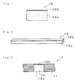

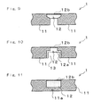


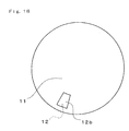

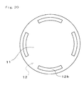

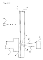


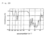
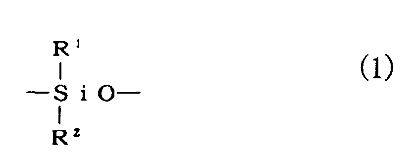


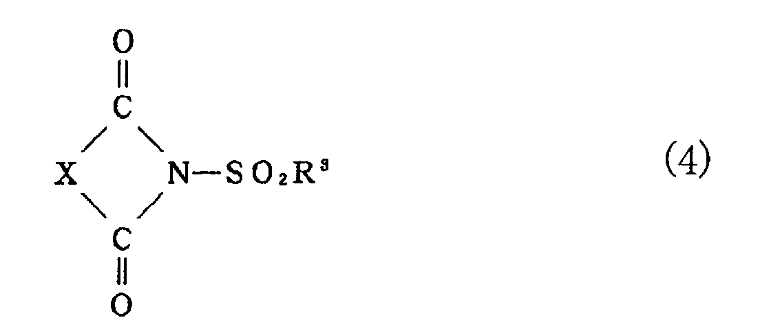 wherein R4 and R5 may be the same or different and denote a monovalent group such as an alkyl group, an aryl group, a halogen-substituted alkyl group and a halogen-substituted aryl group.