EP1306136A1 - Verfahren und Anordnung zur Oberflächenbehandlung - Google Patents
Verfahren und Anordnung zur Oberflächenbehandlung Download PDFInfo
- Publication number
- EP1306136A1 EP1306136A1 EP02079399A EP02079399A EP1306136A1 EP 1306136 A1 EP1306136 A1 EP 1306136A1 EP 02079399 A EP02079399 A EP 02079399A EP 02079399 A EP02079399 A EP 02079399A EP 1306136 A1 EP1306136 A1 EP 1306136A1
- Authority
- EP
- European Patent Office
- Prior art keywords
- liquid
- gas
- venturi
- mixing head
- predefined
- Prior art date
- Legal status (The legal status is an assumption and is not a legal conclusion. Google has not performed a legal analysis and makes no representation as to the accuracy of the status listed.)
- Withdrawn
Links
Images


Classifications
-
- B—PERFORMING OPERATIONS; TRANSPORTING
- B01—PHYSICAL OR CHEMICAL PROCESSES OR APPARATUS IN GENERAL
- B01F—MIXING, e.g. DISSOLVING, EMULSIFYING OR DISPERSING
- B01F23/00—Mixing according to the phases to be mixed, e.g. dispersing or emulsifying
- B01F23/20—Mixing gases with liquids
- B01F23/23—Mixing gases with liquids by introducing gases into liquid media, e.g. for producing aerated liquids
- B01F23/232—Mixing gases with liquids by introducing gases into liquid media, e.g. for producing aerated liquids using flow-mixing means for introducing the gases, e.g. baffles
-
- B—PERFORMING OPERATIONS; TRANSPORTING
- B08—CLEANING
- B08B—CLEANING IN GENERAL; PREVENTION OF FOULING IN GENERAL
- B08B3/00—Cleaning by methods involving the use or presence of liquid or steam
- B08B3/02—Cleaning by the force of jets or sprays
- B08B3/026—Cleaning by making use of hand-held spray guns; Fluid preparations therefor
-
- B—PERFORMING OPERATIONS; TRANSPORTING
- B01—PHYSICAL OR CHEMICAL PROCESSES OR APPARATUS IN GENERAL
- B01F—MIXING, e.g. DISSOLVING, EMULSIFYING OR DISPERSING
- B01F25/00—Flow mixers; Mixers for falling materials, e.g. solid particles
- B01F25/30—Injector mixers
- B01F25/31—Injector mixers in conduits or tubes through which the main component flows
- B01F25/313—Injector mixers in conduits or tubes through which the main component flows wherein additional components are introduced in the centre of the conduit
- B01F25/3131—Injector mixers in conduits or tubes through which the main component flows wherein additional components are introduced in the centre of the conduit with additional mixing means other than injector mixers, e.g. screens, baffles or rotating elements
-
- B—PERFORMING OPERATIONS; TRANSPORTING
- B01—PHYSICAL OR CHEMICAL PROCESSES OR APPARATUS IN GENERAL
- B01F—MIXING, e.g. DISSOLVING, EMULSIFYING OR DISPERSING
- B01F25/00—Flow mixers; Mixers for falling materials, e.g. solid particles
- B01F25/40—Static mixers
- B01F25/42—Static mixers in which the mixing is affected by moving the components jointly in changing directions, e.g. in tubes provided with baffles or obstructions
- B01F25/43—Mixing tubes, e.g. wherein the material is moved in a radial or partly reversed direction
- B01F25/433—Mixing tubes wherein the shape of the tube influences the mixing, e.g. mixing tubes with varying cross-section or provided with inwardly extending profiles
- B01F25/4335—Mixers with a converging-diverging cross-section
-
- B—PERFORMING OPERATIONS; TRANSPORTING
- B01—PHYSICAL OR CHEMICAL PROCESSES OR APPARATUS IN GENERAL
- B01F—MIXING, e.g. DISSOLVING, EMULSIFYING OR DISPERSING
- B01F33/00—Other mixers; Mixing plants; Combinations of mixers
- B01F33/50—Movable or transportable mixing devices or plants
- B01F33/502—Vehicle-mounted mixing devices
- B01F33/5023—Vehicle-mounted mixing devices the vehicle being a trailer which is hand moved or coupled to self-propelling vehicles
-
- B—PERFORMING OPERATIONS; TRANSPORTING
- B05—SPRAYING OR ATOMISING IN GENERAL; APPLYING FLUENT MATERIALS TO SURFACES, IN GENERAL
- B05B—SPRAYING APPARATUS; ATOMISING APPARATUS; NOZZLES
- B05B7/00—Spraying apparatus for discharge of liquids or other fluent materials from two or more sources, e.g. of liquid and air, of powder and gas
- B05B7/02—Spray pistols; Apparatus for discharge
- B05B7/04—Spray pistols; Apparatus for discharge with arrangements for mixing liquids or other fluent materials before discharge
- B05B7/0416—Spray pistols; Apparatus for discharge with arrangements for mixing liquids or other fluent materials before discharge with arrangements for mixing one gas and one liquid
- B05B7/0433—Spray pistols; Apparatus for discharge with arrangements for mixing liquids or other fluent materials before discharge with arrangements for mixing one gas and one liquid with one inner conduit of gas surrounded by an external conduit of liquid upstream the mixing chamber
-
- B—PERFORMING OPERATIONS; TRANSPORTING
- B01—PHYSICAL OR CHEMICAL PROCESSES OR APPARATUS IN GENERAL
- B01F—MIXING, e.g. DISSOLVING, EMULSIFYING OR DISPERSING
- B01F25/00—Flow mixers; Mixers for falling materials, e.g. solid particles
- B01F25/30—Injector mixers
- B01F25/31—Injector mixers in conduits or tubes through which the main component flows
- B01F25/312—Injector mixers in conduits or tubes through which the main component flows with Venturi elements; Details thereof
-
- B—PERFORMING OPERATIONS; TRANSPORTING
- B08—CLEANING
- B08B—CLEANING IN GENERAL; PREVENTION OF FOULING IN GENERAL
- B08B2203/00—Details of cleaning machines or methods involving the use or presence of liquid or steam
- B08B2203/02—Details of machines or methods for cleaning by the force of jets or sprays
- B08B2203/0217—Use of a detergent in high pressure cleaners; arrangements for supplying the same
Definitions
- the invention relates to a method for treating surfaces, like for example cleaning, disinfecting, degreasing and conservation, according to which a liquid having a predefined liquid pressure and a gas having a predefined gas pressure are mixed in a mixing head, which mixture is subsequently sprayed onto the surface to be treated.
- a method of this kind is known from for example the patent application EP-A-0 934 129.
- water is supplied to the mixing head via a central boring and compressed air is supplied to a second boring, positioned coaxial round the central boring, as a result of which the compressed air sort of drags along the water and adds an extra impulse to the water.
- Both borings end in the open air, which implies that the pressure of the gas in the mixture will be reduced in an undefined manner to the atmospheric pressure. In this process, energy will be lost that might have been used for adding an additional impulse to the water.
- the method according to the invention substantially obviates this drawback and is characterised in that the gas/liquid mixture, prepared in the mixing head, is previously led through a tube, comprising a venturi.
- the overpressure in the mixture is gradually reduced to atmospheric pressure, as known in the art, in the process of which the speed of the mixture will increase.
- the result is that the method according to the invention has a larger cleaning power. This saves time, but also less liquid can be used, which is important because used liquid must normally be cleaned or disposed of in an acceptable manner.
- venturi may give the jet, obtained according to the method, a desired shape. This is possible, as known as such in the art, by giving the venturi a predefined shape. For a venturi having a radial symmetry for example, a conical shaped jet will be produced, while a more elliptically shaped or slot-shaped venturi will produce a fan-shaped jet. Especially the fan-shaped jet turns out to be very effective for cleaning surfaces; because of the high speed of the liquid droplets, the fan-shaped jet cuts free the dirt so to speak off the surface over a large width.
- a favourable realisation of the inventive method is characterised in that as liquid water, provided with previously determined additives is used and that as a gas compressed air is used.
- the additives may be detergents when rooms in the food industry or abattoirs must be cleaned, or disinfectants if the disinfection of for example stables or sheds or vehicles is necessary or even grit, when a surface must be blasted.
- a further favourable realisation is characterised in that the liquid and the gas are prepared and pressurised in a mobile unit and are supplied to a mixing head implemented as a hand-held spray-gun, in which the liquid and the gas are mixed and led through the venturi.
- a venturi enables one to perform the cleaning with a relatively small quantity of cleaning liquid and this in turn enables one to accommodate all necessary components in a mobile unit.
- a hand-held spray gun can be used is a direct consequence of the addition of a venturi. As only a small quantity of water is used, the reaction forces on the spray gun will be small, which means that an operator may operate the spray gun for a prolonged time without a risk that RSI related symptoms might develop.
- a further advantage of a mobile unit is that the utilisation of the method does not require special investments, which does make the method very accessible.
- the invention also relates to an arrangement for treating surfaces, like for example cleaning, disinfecting, degreasing and conservation, comprising a spray head provided with connections to which a liquid having a predefined liquid pressure and a gas having a predefined gas pressure can be supplied, and a mixing head, situated in the spray head, with which the liquid and the gas can be mixed thoroughly, and a nozzle via which the mixed product can be delivered.
- the inventive arrangement is characterised in that between the mixing head and the nozzle a tubular channel is fitted, comprising a venturi. In the venturi, the overpressure in the mixture is gradually reduced to the atmospheric pressure, as known in the art, in the process of which the speed of the mixture will increase. The result is that the arrangement according to the invention can realise a larger cleaning power.
- venturi will perform best when the mixture supplied to it has an at least substantially laminar flow pattern and as a consequence does show little turbulence. This can be accomplished easily, by giving the tubular channel a sufficient length.
- a favourable embodiment of the inventive arrangement is thereto characterised in that a length of the tubular channel measures at least five times the inner diameter of the tubular channel.
- venturi comprises a constriction, obtained by pressing the tubular channel together in one direction.
- a constriction of this kind can be introduced in a simple and reproducible manner, while a venturi of this type will produce a fan-shaped jet, with which a large surface may be cleaned in a single continuous movement.
- a further favourable embodiment of the inventive arrangement is characterised in that the spray head is housed in a hand-held spray gun, provided with two hose connections. Because the arrangement uses such a small amount of water, the forces on the spray head are modest, which in turn makes this design feasible.
- the compressed air is supplied in the mixing head round a central boring, via which water is supplied.
- the compressed air surrounds so to speak the water jet and more or less drags it along.
- the aim of the mixing head is on the other hand to realise thorough mixture of the liquid and the gas. It is thereto characterised in that the mixing head comprises a central boring, for the supply of gas, and a number of peripheral borings, situated round the central boring, for the supply of liquid.
- the invention also relates to a system for the treatment of surfaces, like for example cleaning, disinfecting, degreasing and conservation, comprising an arrangement as described here, for which the system moreover comprises a mobile unit, provided with a pump unit for the liquid, a gas bottle and/or a compressor for the gas.
- the system moreover comprises a mobile unit, provided with a pump unit for the liquid, a gas bottle and/or a compressor for the gas.
- the mobile unit moreover comprises at least one supply vessel for an additive, like for example a detergent, and a dosage device with an injector for adding the additive to the liquid. It is possible then for example to prefoam a surface to be cleaned by spraying water with a detergent and then, after some reaction time, to clean the surface with water. In a final treatment, a disinfectant can be added to the water.
- an additive like for example a detergent
- a dosage device with an injector for adding the additive to the liquid for example to prefoam a surface to be cleaned by spraying water with a detergent and then, after some reaction time, to clean the surface with water.
- a disinfectant can be added to the water.
- Fig. 1 schematically represents a possible embodiment of the system, comprising a mobile unit 1, in which a compressor 2 is placed which supplies compressed air via a hose 3 to a spray head 4, and a pump 5, which supplies water, from a supply vessel 6 or via a coupling from the water supply system, to spray head 4 via a hose 7, and in which moreover three containers 8a,8b,8c are placed, in which additives are stored that may be added to the water with the aid of valves, injectors and/or dosage devices, as such well known in the art, which can be controlled with the aid of a control panel 9.
- Spray head 4 contains a mixing head 10, in which the water and the compressed air are mixed thoroughly. This mixture leaves spray head 4 via a valve 11 and a tube 12 which is provided with a venturi so as to form a cone-shaped or fan-shaped jet which contains relatively little water but which nevertheless has an exceptionally strong cleaning effect.
- Fig. 2A represents more in detail a possible embodiment of the spray head 4, containing a tubular body 13, provided with a synthetic insulation layer 14, which is on a first side provided with a standard water hose connection 15 and a connection 16 for hose 3, via which compressed air is supplied.
- Water and compressed air are mixed in mixing head 10, here consisting of a metal disk through which via a central opening the air is admitted and via a number of coaxial arranged openings the water is added. This type of mixing causes much turbulence, necessary for obtaining a very thorough mixture. Subsequently the mixture is conducted to a valve 11, which is screwed onto tubular body 13, and to a tube 12, screwed onto valve 11, which is provided with a venturi 17.
- valve 11 may be replaced by for example electrically controlled valves, situated near the connections 15,16 or in mobile unit 1.
- Spray head 4 is completely manufactured of stainless steel, with the exception of insulation layer 14, and is therefore well suited for spraying all possible types of other media.
- Compressed air may for example be replaced by steam when for example chewing gum must be removed or the water may be replaced by a solvent when a surface must be degreased.
- Fig. 2B represents in a cross-section according to the line AA' in Fig. 2A the mixing head 10, consisting of a metal disk provided with a central opening 18 via which the air is admitted and via a number of coaxial arranged openings 19a,19b,.. via which the water is admixed.
- mixing head 10 is provided with six peripheral openings, but this number may be chose larger if more liquid is to be added to the mixture.
- the diameter of the peripheral openings is for example 1 millimetre and the diameter of the central opening for example 3 millimetre.
- Fig. 3 represents an alternative embodiment of the spray head, comprising a tubular body 13, provided with a synthetic insulation layer 14, which is on one side provided with a standard pistol grip 20, connected to hose 7, via which water can be supplied and with a connection 16 for hose 3, via which compressed air can be supplied.
- Water and compressed air are mixed in mixing head 10, here consisting of a metal disk provided with a central opening 18 via which the air is admitted and via a number of coaxial arranged openings 19a,19b,.. via which the water is admixed. Subsequently the mixture is conducted to a tube 12, screwed onto a tubular body 13, which tube 12 is provided with a venturi 17.
- the turbulent water/air mixture is forced into a more laminar flow and in venturi 17 the mixture may expand in a controlled manner, in the process of which the speed of the mixture significantly increases.
- the spray head can be operated via pistol grip 20, via which water is supplied to mixing head 10.
- a pressure drop or a flow will be detected and a valve will be opened which admits compressed air to flow via hose 3 and connection 16 to mixing head 10.
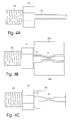
- Venturi tube 12 is made of stainless steel, has a length of for example 30 millimetre, an inner diameter of 5 millimetre and it is integrated with a nut 21 and a threaded end 22, in such a manner that it can easily be replaced when a liquid/gas mixture jet with a different type of cone-beam or fan-beam is desired.
- Fig. 4B represents the venturi tube 12, after the constriction 17 has been introduced with the aid of two clamping blocks 23a,23b in a press that is not shown here.
- Constriction 17 is slit-shaped here, with a width of the slit of for example 1.5 millimetre. In this way, a fan-beamed jet can be obtained having a beam width of about 10x45 degrees. It is also possible to carry out the clamping process while venturi tube 12 is rotated round its longitudinal axis. A constriction having a radial symmetry can thus be obtained with an inner diameter of for example 2.5 millimetre. In this way, cone-shaped jet can be obtained having a beam width of about 20 degrees.
- Fig. 4C represents the venturi tube after a protective cover 24 has been mounted.
- Fig. 5 represents in a block schematic diagram a possible embodiment of the mobile unit 1, with compressor 2, which supplies compressed air via a hose reel 25 and hose 3, a pump 5 which supplies water via hose reel 25 and hose 7, and three containers 8a,8b,8c in which additives are stored.
- compressor 2 which supplies compressed air via a hose reel 25 and hose 3
- pump 5 which supplies water via hose reel 25 and hose 7, and three containers 8a,8b,8c in which additives are stored.
- the water is supplied to one of the three dosage devices 27a,27b,27c, well known in the art, and with the valves 28a,28b,28c one of the containers 8a,8b,8c is connected at the same time to the corresponding dosage device, so that the desired additive is indeed added.
- valves 29a,29b,29c are provided, which prevent compressed air from leaking towards the dosage devices when valve 11 of spray head 4 is closed. This is necessary, as the pressure of the compressed air is always chosen higher than the water pressure.
- the water pressure is for example 2-10 bar, while the pressure of the compressed air amounts to 6-15 bar.
- the system can be used for cleaning surfaces, but it may also be used for spraying plant-protecting means, for disinfecting cattle, in a car wash and for cleaning frontages and sewers.
Landscapes
- Chemical & Material Sciences (AREA)
- Chemical Kinetics & Catalysis (AREA)
- Dispersion Chemistry (AREA)
- Nozzles (AREA)
Applications Claiming Priority (2)
| Application Number | Priority Date | Filing Date | Title |
|---|---|---|---|
| NL1019212A NL1019212C2 (nl) | 2001-10-23 | 2001-10-23 | Werkwijze en inrichting voor het behandelen van oppervlakken. |
| NL1019212 | 2001-10-23 |
Publications (1)
| Publication Number | Publication Date |
|---|---|
| EP1306136A1 true EP1306136A1 (de) | 2003-05-02 |
Family
ID=19774196
Family Applications (1)
| Application Number | Title | Priority Date | Filing Date |
|---|---|---|---|
| EP02079399A Withdrawn EP1306136A1 (de) | 2001-10-23 | 2002-10-22 | Verfahren und Anordnung zur Oberflächenbehandlung |
Country Status (2)
| Country | Link |
|---|---|
| EP (1) | EP1306136A1 (de) |
| NL (1) | NL1019212C2 (de) |
Cited By (11)
| Publication number | Priority date | Publication date | Assignee | Title |
|---|---|---|---|---|
| GB2389037A (en) * | 2002-05-31 | 2003-12-03 | Harold Jayes | Fluid jetting apparatus for rejuvenation of artificial sports surfaces |
| JP2008536671A (ja) * | 2005-04-19 | 2008-09-11 | スペシャル コーティング ラボラトリ インターナショナル | 眼科用レンズ又はその他の物質を洗浄するための洗浄器に用いる高圧液体噴射ノズル |
| WO2013087956A1 (es) * | 2011-12-14 | 2013-06-20 | Universidad De Zaragoza | Equipo electromecánico para la aplicación de mezclas de productos sólidos y líquidos para la limpieza y rehabilitación de superficies y procedimientos de aplicación de la mezcla |
| US8685174B2 (en) | 2009-08-19 | 2014-04-01 | Conopco, Inc. | Process for cleaning hard surfaces |
| US8800089B2 (en) | 2009-08-19 | 2014-08-12 | Conopco, Inc. | Process for cleaning teeth |
| US8910889B2 (en) | 2009-08-19 | 2014-12-16 | Conopco, Inc. | Process and a device to clean substrates |
| CN104525410A (zh) * | 2015-01-08 | 2015-04-22 | 张文明 | 利用单喷头水气混合装置形成不同尺寸水滴的方法 |
| EP2871003A1 (de) * | 2013-11-08 | 2015-05-13 | Bendel Werkzeuge Inhaber Frank Bendel | Reinigungsgerät |
| EP2835420A4 (de) * | 2012-04-02 | 2016-07-06 | O2 Engineering Ltd | Internes reinigungsmittel für dieselmotor und reinigungssystem damit |
| JPWO2021014610A1 (de) * | 2019-07-24 | 2021-01-28 | ||
| FR3139484A1 (fr) * | 2022-09-14 | 2024-03-15 | Heurtaux S.A.S. | Dispositif de lavage avec air |
Families Citing this family (1)
| Publication number | Priority date | Publication date | Assignee | Title |
|---|---|---|---|---|
| CN109047064A (zh) * | 2018-09-11 | 2018-12-21 | 张冲 | 一种建筑施工用基础清洁装置 |
Citations (8)
| Publication number | Priority date | Publication date | Assignee | Title |
|---|---|---|---|---|
| US3575348A (en) * | 1968-09-09 | 1971-04-20 | Lincoln Mfg Co | Device for washing and rinsing |
| GB1263315A (en) * | 1965-07-15 | 1972-02-09 | Lyn Edward Carolin | Improvements in apparatus and method for cleaning fixed windows |
| EP0264689A1 (de) * | 1986-10-09 | 1988-04-27 | Ulrich Brandstetter | Vorrichtung zum Erzeugen von Schaum |
| JPH03296475A (ja) * | 1990-04-13 | 1991-12-27 | Eikichi Yamaharu | 洗浄装置 |
| US5443211A (en) * | 1992-01-30 | 1995-08-22 | The Stanley Works | Spray machine for giving a texture to drywall |
| JPH07265751A (ja) * | 1994-03-30 | 1995-10-17 | Asahi Sanac Kk | エアースプレイガン用アタッチメント |
| JPH10235234A (ja) * | 1997-02-26 | 1998-09-08 | Hokukan:Kk | 被洗浄面の洗浄ノズル |
| EP0934129A1 (de) | 1996-10-24 | 1999-08-11 | H.T. Research B.V. | Verfahren und vorrichtung zum reinigen einer schmutzigen oberfläche |
-
2001
- 2001-10-23 NL NL1019212A patent/NL1019212C2/nl not_active IP Right Cessation
-
2002
- 2002-10-22 EP EP02079399A patent/EP1306136A1/de not_active Withdrawn
Patent Citations (8)
| Publication number | Priority date | Publication date | Assignee | Title |
|---|---|---|---|---|
| GB1263315A (en) * | 1965-07-15 | 1972-02-09 | Lyn Edward Carolin | Improvements in apparatus and method for cleaning fixed windows |
| US3575348A (en) * | 1968-09-09 | 1971-04-20 | Lincoln Mfg Co | Device for washing and rinsing |
| EP0264689A1 (de) * | 1986-10-09 | 1988-04-27 | Ulrich Brandstetter | Vorrichtung zum Erzeugen von Schaum |
| JPH03296475A (ja) * | 1990-04-13 | 1991-12-27 | Eikichi Yamaharu | 洗浄装置 |
| US5443211A (en) * | 1992-01-30 | 1995-08-22 | The Stanley Works | Spray machine for giving a texture to drywall |
| JPH07265751A (ja) * | 1994-03-30 | 1995-10-17 | Asahi Sanac Kk | エアースプレイガン用アタッチメント |
| EP0934129A1 (de) | 1996-10-24 | 1999-08-11 | H.T. Research B.V. | Verfahren und vorrichtung zum reinigen einer schmutzigen oberfläche |
| JPH10235234A (ja) * | 1997-02-26 | 1998-09-08 | Hokukan:Kk | 被洗浄面の洗浄ノズル |
Non-Patent Citations (3)
| Title |
|---|
| PATENT ABSTRACTS OF JAPAN vol. 016, no. 133 (C - 0925) 6 April 1992 (1992-04-06) * |
| PATENT ABSTRACTS OF JAPAN vol. 1996, no. 02 29 February 1996 (1996-02-29) * |
| PATENT ABSTRACTS OF JAPAN vol. 1998, no. 14 31 December 1998 (1998-12-31) * |
Cited By (16)
| Publication number | Priority date | Publication date | Assignee | Title |
|---|---|---|---|---|
| GB2389037A (en) * | 2002-05-31 | 2003-12-03 | Harold Jayes | Fluid jetting apparatus for rejuvenation of artificial sports surfaces |
| JP2008536671A (ja) * | 2005-04-19 | 2008-09-11 | スペシャル コーティング ラボラトリ インターナショナル | 眼科用レンズ又はその他の物質を洗浄するための洗浄器に用いる高圧液体噴射ノズル |
| US8449688B2 (en) * | 2005-04-19 | 2013-05-28 | Jean Gebrig | High-pressure liquid atomisation nozzle for a machine for cleaning optical lenses or other substrates |
| US8685174B2 (en) | 2009-08-19 | 2014-04-01 | Conopco, Inc. | Process for cleaning hard surfaces |
| US8800089B2 (en) | 2009-08-19 | 2014-08-12 | Conopco, Inc. | Process for cleaning teeth |
| US8910889B2 (en) | 2009-08-19 | 2014-12-16 | Conopco, Inc. | Process and a device to clean substrates |
| WO2013087956A1 (es) * | 2011-12-14 | 2013-06-20 | Universidad De Zaragoza | Equipo electromecánico para la aplicación de mezclas de productos sólidos y líquidos para la limpieza y rehabilitación de superficies y procedimientos de aplicación de la mezcla |
| EP2835420A4 (de) * | 2012-04-02 | 2016-07-06 | O2 Engineering Ltd | Internes reinigungsmittel für dieselmotor und reinigungssystem damit |
| US9617505B2 (en) | 2012-04-02 | 2017-04-11 | O2 Engineering., Ltd. | Internal cleaning agent for diesel engine and cleaning system using the same |
| EP2871003A1 (de) * | 2013-11-08 | 2015-05-13 | Bendel Werkzeuge Inhaber Frank Bendel | Reinigungsgerät |
| CN104525410A (zh) * | 2015-01-08 | 2015-04-22 | 张文明 | 利用单喷头水气混合装置形成不同尺寸水滴的方法 |
| JPWO2021014610A1 (de) * | 2019-07-24 | 2021-01-28 | ||
| WO2021014610A1 (ja) * | 2019-07-24 | 2021-01-28 | 旭サナック株式会社 | ノズル、および液体噴射装置 |
| CN114126764A (zh) * | 2019-07-24 | 2022-03-01 | 旭灿纳克株式会社 | 喷嘴及液体喷射装置 |
| US12183598B2 (en) | 2019-07-24 | 2024-12-31 | Asahi Sunac Corporation | Nozzle and liquid ejection system |
| FR3139484A1 (fr) * | 2022-09-14 | 2024-03-15 | Heurtaux S.A.S. | Dispositif de lavage avec air |
Also Published As
| Publication number | Publication date |
|---|---|
| NL1019212A1 (nl) | 2001-11-29 |
| NL1019212C2 (nl) | 2002-08-20 |
Similar Documents
| Publication | Publication Date | Title |
|---|---|---|
| US5299740A (en) | Plural component airless spray gun with mechanical purge | |
| EP1306136A1 (de) | Verfahren und Anordnung zur Oberflächenbehandlung | |
| US4927079A (en) | Plural component air spray gun and method | |
| US7087123B2 (en) | Cleaning and sanitizing system | |
| US5487695A (en) | Blast nozzle combined with multiple tip water atomizer | |
| US3179341A (en) | Spray gun | |
| US3741808A (en) | Tank cleaner | |
| JPS6467272A (en) | Spray nozzle, sprayer and method for use thereof | |
| US4289276A (en) | Improved apparatus for cleaning vehicles | |
| BRPI0905939B1 (pt) | processo para limpar um substrato e dispositivo para limpeza de tecido sujo | |
| EP0120317B1 (de) | Reinigungs- und Spülgerät | |
| US5814162A (en) | Air and spray nozzle | |
| US20080028556A1 (en) | Paint brush cleaning device | |
| DE10065825B4 (de) | Hochdruckreinigungssystem, Reinigungsverfahren und Düseneinheit hierfür | |
| EP3065851B1 (de) | Reinigungseinheit und verfahren zur verbesserten herstellung von schaum für reinigungszwecke | |
| GB2283906A (en) | Cleaning system and lance | |
| US3194500A (en) | Surface degreasing and cleaning gun | |
| JP2013146719A (ja) | 洗浄装置および洗浄方法 | |
| JPH03296475A (ja) | 洗浄装置 | |
| US3059858A (en) | Applicator system and fluid projecting gun therefor | |
| RU2284231C2 (ru) | Установка для очистки поверхностей | |
| JP2004283764A (ja) | 高圧オゾン洗浄方法及び装置 | |
| JPH09509090A (ja) | 表面に泡の層を供給するための方法並びにこの方法を実施するための泡噴射装置 | |
| EP1088602A1 (de) | Druckluftbetriebene Reinigungspistole | |
| RU2085300C1 (ru) | Пистолет-распылитель |
Legal Events
| Date | Code | Title | Description |
|---|---|---|---|
| PUAI | Public reference made under article 153(3) epc to a published international application that has entered the european phase |
Free format text: ORIGINAL CODE: 0009012 |
|
| AK | Designated contracting states |
Designated state(s): AT BE BG CH CY CZ DE DK EE ES FI FR GB GR IE IT LI LU MC NL PT SE SK TR |
|
| AX | Request for extension of the european patent |
Extension state: AL LT LV MK RO SI |
|
| 17P | Request for examination filed |
Effective date: 20031103 |
|
| AKX | Designation fees paid |
Designated state(s): AT BE BG CH CY CZ DE DK EE ES FI FR GB GR IE IT LI LU MC NL PT SE SK TR |
|
| 17Q | First examination report despatched |
Effective date: 20060302 |
|
| STAA | Information on the status of an ep patent application or granted ep patent |
Free format text: STATUS: THE APPLICATION IS DEEMED TO BE WITHDRAWN |
|
| 18D | Application deemed to be withdrawn |
Effective date: 20080805 |