EP1304578A2 - Verfahren und Vorrichtung zur Bestimmung der Drehzahl einer Welle - Google Patents
Verfahren und Vorrichtung zur Bestimmung der Drehzahl einer Welle Download PDFInfo
- Publication number
- EP1304578A2 EP1304578A2 EP02102324A EP02102324A EP1304578A2 EP 1304578 A2 EP1304578 A2 EP 1304578A2 EP 02102324 A EP02102324 A EP 02102324A EP 02102324 A EP02102324 A EP 02102324A EP 1304578 A2 EP1304578 A2 EP 1304578A2
- Authority
- EP
- European Patent Office
- Prior art keywords
- encoder
- gap
- sensor
- characteristic value
- assigned
- Prior art date
- Legal status (The legal status is an assumption and is not a legal conclusion. Google has not performed a legal analysis and makes no representation as to the accuracy of the status listed.)
- Withdrawn
Links
Images

Classifications
-
- F—MECHANICAL ENGINEERING; LIGHTING; HEATING; WEAPONS; BLASTING
- F02—COMBUSTION ENGINES; HOT-GAS OR COMBUSTION-PRODUCT ENGINE PLANTS
- F02D—CONTROLLING COMBUSTION ENGINES
- F02D41/00—Electrical control of supply of combustible mixture or its constituents
- F02D41/0097—Electrical control of supply of combustible mixture or its constituents using means for generating speed signals
-
- G—PHYSICS
- G01—MEASURING; TESTING
- G01P—MEASURING LINEAR OR ANGULAR SPEED, ACCELERATION, DECELERATION, OR SHOCK; INDICATING PRESENCE, ABSENCE, OR DIRECTION, OF MOVEMENT
- G01P3/00—Measuring linear or angular speed; Measuring differences of linear or angular speeds
- G01P3/42—Devices characterised by the use of electric or magnetic means
- G01P3/44—Devices characterised by the use of electric or magnetic means for measuring angular speed
- G01P3/48—Devices characterised by the use of electric or magnetic means for measuring angular speed by measuring frequency of generated current or voltage
- G01P3/481—Devices characterised by the use of electric or magnetic means for measuring angular speed by measuring frequency of generated current or voltage of pulse signals
- G01P3/489—Digital circuits therefor
Definitions
- the invention relates to a method for determination the speed of a shaft, especially a drive shaft of an internal combustion engine in a motor vehicle, on the rotating a number of scannable transducers in equidistant Encoder positions, as well as a defined encoder gap are. It also relates to a device to carry out the procedure.
- From DE 44 09 846 A1 is a "speed detection device for a rotating body ". With the help of the disclosed there The object is solved, the speed of a rotating body while correcting a Detection error. As the cause of such registration errors z.
- the object of this patent is now aimed at eliminating precisely these irregularities in the rotational movement by means of a calculation and to represent a harmonious speed curve that is as uniform as possible. Due to the lack of a defined reference mark z. B. an encoder gap on the signal rotor, an absolute rotation angle determination is not possible. Furthermore, periodically occurring rotational irregularities of the rotating body, such as, for example, a crankshaft of an internal combustion engine, cannot be detected by this arrangement, since these are eliminated by the specified algorithm.
- the speed of the internal combustion engine is recorded usually using a so-called 60-2 encoder wheel as Part of a speed or crankshaft sensor on the machine shaft arranged and circulating in equidistant Sensor positions of scannable signal transmitters in the form of teeth or active magnetic sections.
- 60-2 encoder wheel as Part of a speed or crankshaft sensor on the machine shaft arranged and circulating in equidistant Sensor positions of scannable signal transmitters in the form of teeth or active magnetic sections.
- This encoder gap can be determined by the engine control of the Internal combustion engine are recognized and usually serves as Indexing or reference mark to determine an absolute Angular position of the shaft.
- Speed or speed measurement is a Movement difference measurement between two relative to each other moving objects, namely a stationary sensor head and a pulse wheel rotating with the shaft.
- the Path or angle measurement is usually carried out by Counting signal pulses, taking the time interval between two teeth acting as signal generators and on the other the respective tooth number is recorded. By capturing the relative tooth or signal generator number is the relative position between the speed sensor or pulse wheel and the Sensor head can be determined.
- the individual teeth or partitions and thus the respective Numbers assigned to encoder positions are therefore with a 60-2 encoder wheel numbers or positions 1 to 60 or 0 to 59.
- such a sensor wheel with n divisions or Assigned teeth corresponding to n encoder positions. From the Time difference or the time interval between two neighboring ones Teeth or divisions and thus between two neighboring ones Encoder positions, the speed in this Path section between two encoder positions and thus the Determine the speed of the shaft.
- Another disruptive effect is a production-related one in particular Tolerance especially of those signal pulses, that are directly adjacent to the donor gap. So can depending on the design, the manufacturing process and the Sensor properties significantly larger tolerances in this Range occur than with other divisions or encoder positions. Also the tolerance for the distance from a signal pulse to the next signal pulse by a factor 10 and thus be an order of magnitude smaller than the tolerance the last division and thus the last encoder position before the donor gap. This automatically leads to a significant one Error in determining the speed. The control the electrical machine, i.e. of the starter generator, can thus based on incorrect input variables, so that consequently result in incorrect output voltages and frequencies. This in turn inevitably leads to a large pulse or transient disturbance in torque and also in Battery power.
- the invention is therefore based on the object, a particular suitable method for determining the speed of a shaft by means of a speed sensor having an encoder gap specify, while avoiding the disadvantages mentioned The most accurate possible speed detection is guaranteed. Furthermore, one intended to carry out the method in particular suitable device can be specified.
- this object is achieved according to the invention solved by the features of claim 1.
- time interval characteristic values that of successive signal generators emitted signal pulses determined, one encoder position in the area of the encoder gap as an interval parameter the characteristic value is assigned that for one by one Predeterminable angle offset encoder position determined has been.
- each suitable characteristic value for the corresponding encoder position in the area of the donor gap is expediently carried out by means of of a self-learning algorithm that is used during a learning phase at the encoder positions in the area of the offset angle Characteristic values and their changes are observed and from them the Derives substitute values or substitute characteristic values for the encoder gap.
- the invention is based on the consideration that Recognized periodically and thus more symmetrically Fluctuations in the speed of a multi-cylinder internal combustion engine the conditions at least approximately in each period same.
- This is recognized for a four-stroke engine due to the principle of intermittent energy input of the internal combustion engine, a pulsation of the instantaneous speed of the engine and thus that connected to it or coupled drive shaft, the periodicity of this process divide a degree of 720 ° for a four-stroke engine by the number of cylinders. With a four-cylinder engine the periodicity is therefore 180 °, which is two cycles (Ignitions) per shaft revolution or mechanical revolution of the existing starter generator.
- the observation of the speed curve of a previous one Period can therefore be determined by the constructive features of the Internal combustion engine as an estimate for the unobservable Course in the area of the donor gap - and also as a replacement value for measurement or characteristic values in the Environment of the sensor gap - can be used. So it offers with a four-cylinder four-stroke engine to observe the course, which is opposite the donor gap, i.e. around Is offset by 180 °. Due to the symmetry of the motor, it can be expected that this behavior is offset by 180 ° Repeat encoder position. Hence, non-profitable or to an undesirable degree of tolerance or characteristic values are replaced by such characteristic values that an existing encoder position by a correspondingly offset angle be recorded. Characteristic values can also be based on the knowledge gained can be qualitatively improved.
- a self-learning system is thus provided overall, whose only uncertainty is the change in Combustion parameters from one cylinder to the next is. Experience has shown that these parameters remain on average very similar, only when suddenly accelerating or Decelerate with comparatively large changes is.
- This self-learning system also enables unwanted ones Tolerant encoder positions or divisions, which are adjacent to the encoder gap, by means of corresponding codes Replace estimates where the estimation error is smaller than the measurement error.
- This also enables simple, self-learning system taking advantage of the constructive Symmetry of multi-cylinder internal combustion engines best possible adaptation to changing operating conditions of the Internal combustion engine of a motor vehicle, in particular in connection with a starter generator.
- the time difference is expediently used as the characteristic value between two similar flanks of a rectangular one Signal pulse used. Simultaneously with the respective The corresponding encoder position or is also a characteristic value Item number recorded.
- the corresponding characteristic values are expedient cached. These stored characteristic values are then after passing the last encoder position before the encoder gap used as characteristic values at the encoder positions there. In addition, other characteristic values can also be assigned to those encoder positions are saved, which in turn periodically offset to encoder positions with high tolerances that especially for donor positions adjacent to the donor gap occur.
- the encoder positions in the area of the encoder gap are advantageously those characteristic values assigned to a determined a fraction of 360 ° lying encoder position have been.
- the corresponding factor results from this the number of themselves periodically within a shaft revolution at least approximately repeating characteristic values and from the number of degrees between two successive signal generators.
- the characteristic value repeats after one Rotation angle of 180 ° and is - at z.
- B a number of 60 signal generators distributed around the circumference - the Degrees between two successive signal generators 6 °, so - based on position number 1 or 0 the immediately behind the encoder gap - at the encoder position 30 or 29, as can be seen, at least approximately the same conditions as in the donor gap lying encoder position 60 or 59, at which no signal transmitter is available.
- the device comprises a speed sensor that is operated by a a signal generator with encoder gap on the scope of the Signal pulses corresponding to equidistant encoder positions receives. It also includes a computer unit with a timer module that shows the time difference in succession Signal impulses recorded and the respective encoder positions assigned time interval characteristic values and expediently outputs corresponding item numbers. For investigation the respective encoder position is after each shaft revolution with the first signal generator behind or after that as a reference mark serving encoder gap started a counter.
- An evaluation module of the computer unit arranges everyone self-learning Encoder position in the area of the encoder gap a characteristic value to which one is periodically offset by the specified angle arranged encoder position is assigned. The assignment is made by means of an algorithm of the evaluation module, by this is the periodically offset angle in a learning phase determined characteristic value in the donor gap for the corresponding Uses encoder position.
- the computer unit also includes a characteristic value memory in which at least one in Range of the predetermined angle lying encoder position assigned Time interval characteristic value is stored. This Characteristic value or one corresponding to the encoder positions in the encoder gap The number of characteristic values is then shifted periodically read out from the memory and the corresponding encoder positions assigned in the donor gap.
- the periodically offset angle corresponds to a multiple the number of degrees between two neighboring encoder positions.
- the number of encoder positions corresponding to the offset depends on the respective periodicity of the symmetrical Speed fluctuations. With a signal generator with 60 divisions and a periodicity of 120 ° in the case of a six-cylinder internal combustion engine or of 180 ° in the case of a four-cylinder internal combustion engine this results in an offset of 20 or 30 encoder positions.
- the computer unit comprises a control module connected to the evaluation module and is determined by this one from the time interval characteristic values Speed actual value received.
- the actual speed value represents the actual shaft speed particularly precisely, which also at least approximately in the area of the donor gap is correctly recorded.
- the device is therefore particularly suitable for control a starter generator of a motor vehicle with a Combustion engine.
- a starter generator can this due to the comparatively correctly recorded React speed with correspondingly ideal behavior. Thereby are particularly fluctuations in torque and / or the battery current with such a starter generator equipped motor vehicle avoided.
- FIG. 1 schematically shows a device for determining the Speed N of a shaft 1, which is part of the embodiment mechanical drive structure of a motor vehicle with a Internal combustion engine or an internal combustion engine 2 and with a starter generator 3 in the form of a three-phase machine is. Their rotor or rotor sits on the driven crankshaft 1, while the stator is arranged stationary.
- the Internal torque generated by the internal combustion engine 2 leads to one corresponding to the engine speed and by means of a Speed or crankshaft sensor 5 detected actual speed N the crankshaft 1.
- crankshaft 1 is included on the circumference a number of scannable signal transmitters SG in equidistant Provide encoder positions n.
- Timer 7 passes to a computing unit 8.
- the timer 7 delivers a time interval characteristic value for each encoder position n on the output side T (n), the time difference between two similar edges F of successive signal generators SG emitted signal pulses SI corresponds. simultaneously the timer 7 delivers the respective time interval characteristic value T (n) assigned encoder position or position number n.
- the counter 9 starts again.
- the angular velocity ⁇ (T) which is equivalent to the rotational speed information and thus to the actual rotational speed N, is fed to the control module 4 of the computer unit 8 as an input variable, where T is the detected tooth or encoder position time.
- the control module 4 which also includes the functionality of the control or regulation of the starter generator 3, supplies a corresponding, for. B. three-phase control signal S to the starter generator 3.
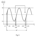
- T (n) To determine suitable time interval parameters T (n) to assign the encoder positions n in the encoder gap GL are known to be symmetrical fluctuation behavior the shaft speed N as used in 3 based on speed fluctuations of a four-cylinder internal combustion engine 2 is illustrated in simplified form. shown are the periodic fluctuations in speed within of a 360 ° angle of a shaft revolution by one on the ordinate removed idling speed of 750, for example U / min.
- the division of the encoder wheel 6 is on the abscissa the 60 encoder positions n in the exemplary embodiment.
- the cyclically repeating can be seen Behavior of speed fluctuations, assuming can be that the speed ratios change periodically to repeat.
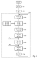
- a suitable characteristic value ratio can also be used during the learning phase within the program or program sub-steps 103a to 103f , a suitable characteristic value difference or a combination thereof.
Landscapes
- Engineering & Computer Science (AREA)
- Chemical & Material Sciences (AREA)
- Combustion & Propulsion (AREA)
- Mechanical Engineering (AREA)
- General Engineering & Computer Science (AREA)
- Physics & Mathematics (AREA)
- General Physics & Mathematics (AREA)
- Combined Controls Of Internal Combustion Engines (AREA)
- Transmission And Conversion Of Sensor Element Output (AREA)
Abstract
Description
Durch das Fehlen einer definierten Referenzmarke z. B. einer Geberlücke auf dem Signalrotor ist eine absolute Drehwinkelbestimmung nicht möglich.
Weiterhin können durch diese Anordnung periodisch auftretende Drehungleichförmigkeiten des Drehkörpers, wie zum Beispiel einer Kurbelwelle eines Verbrennungsmotors nicht erfasst werden, da diese durch den angegebenen Algorithmus eliminiert werden.
- FIG 1
- schematisch in einem Blockschaltbild eine Vorrichtung zur Drehzahlbestimmung einer Welle mit einem Drehzahlsensor und einem lückenbehafteten Signalgeber sowie mit einer Rechnereinheit mit selbstlernendem Auswertealgorithmus,
- FIG 2
- ein von der Rechnereinheit verarbeitetes Impulssignal des Drehzahlsensors,
- FIG 3
- den Signalverlauf einer Drehzahlschwankung der Wellendrehzahl, und
- FIG 4
- ein Flussdiagramm des Auswertealgorithmus.
Claims (10)
- Verfahren zur Bestimmung der Drehzahl (N) einer Welle (1), an der umlaufend eine Anzahl von abtastbaren Signalgebern (SG) in äquidistanten Geberpositionen (n), sowie eine Geberlücke (GL) angeordnet sind,wobei Zeitintervall-Kennwerte (T(n)) der von aufeinander folgenden Signalgebern (SG) abgegebenen Signalimpulse (SI) ermittelt werden, undwobei mindestens einer Geberposition (n) im Bereich der Geberlücke (GL) ein Zeitintervall-Kennwert zugeordnet wird, der für eine, um einen vorgegebenen Winkel (α) periodisch versetzt angeordnete, Geberposition (N) ermittelt wird.
- Verfahren nach Anspruch 1, bei dem als Kennwert (T(n)) jeweils die Zeitdifferenz zwischen zwei gleichartigen Flanken (F) eines rechteckförmigen Signalimpulses (SI) herangezogen werden, wobei zeitgleich mit dem jeweiligen Kennwert (T(n)) die diesem zugeordnete Geberposition (n) erfasst wird.
- Verfahren nach Anspruch 1 oder 2, bei dem im Bereich des versetzten Winkels (α) eine der Anzahl der im Bereich der Geberlücke (GL) fehlenden Signalgeber (SG) entsprechende Anzahl von Kennwerten (T(n)) von aufeinander folgend abgegebenen Signalimpulsen (SI) gespeichert und bei Erreichen der Geberlücke (GL) als Zeitintervall-Kennwert (T(n)) herangezogen werden.
- Verfahren nach einem der Ansprüche 1 bis 3, bei dem einer ersten Geberposition (n) im Bereich der Geberlücke (GL) der an der Geberposition n = a-1 . b-1 . 360° ermittelte Kennwert (T(n)) zugeordnet wird, wobei a die Anzahl von sich innerhalb einer Wellenumdrehung periodisch zumindest annähernd wiederholenden Kennwerten (T(n)) und b die Gradzahl zwischen zwei aufeinander folgenden Signalgebern (SG) ist.
- Verfahren nach einem der Ansprüche 1 bis 4, bei dem der der jeweiligen Geberposition (n) im Bereich der Geberlücke (GL) zugeordnete Kennwert (T(n)) aus dem Kennwert (T(n)) des an der letzten Geberposition (n) vor der Geberlücke (GL) erfassten Signalimpulses (SI) und dem Verhältnis oder der Differenz der Kennwerte (T(n)) von an zwei Geberpositionen (n) im Bereich des versetzten Winkels (α) erfassten Signalimpulsen (SI) ermittelt wird.
- Vorrichtung zur Bestimmung der Drehzahl (N) einer Welle (1), insbesondere zur Durchführung des Verfahrens nach einem der Ansprüche 1 bis 5, mit einem Drehzahlsensor (5), der von einem eine Geberlücke (GL) aufweisenden Signalgeber (6) mit am Umfang der Welle (1) äquidistanten Geberpositionen (n) Signalimpulse (SI) empfängt, und mit einer Rechnereinheit (8)mit einem Zähler- und Timermodul (7,9), das die Zeitdifferenz aufeinander folgender Signalimpulse (SI) erfasst und den jeweiligen Geberpositionen (n) zugeordnete Zeitintervall-Kennwerte (T(n)) ausgibt, sowiemit einem Auswertemodul (11), dessen Algorithmus jeder Geberposition (n) im Bereich der Geberlücke (GL) einen in einer Lernphase an einem periodisch versetzten Winkel (α) ermittelten Kennwert (T(n)) zuordnet.
- Vorrichtung nach Anspruch 6, wobei die Rechnereinheit (8) einen Kennwertspeicher (10) aufweist, in dem mindestens ein einer im Bereich des vorgegebenen Winkels (α) liegenden Geberposition (n) zugeordneter Zeitintervall-Kennwert (T(n)) hinterlegt ist.
- Vorrichtung nach Anspruch 6 oder 7, wobei das Auswertemodul (11) aus dem der letzten Geberposition (n) vor der Geberlücke (GL) zugeordneten Kennwert (T(n)) und aus mindestens zwei weiteren, im Bereich des versetzten Winkels (α) liegenden Geberpositionen (n) zugeordneten Kennwerten (T(n)) einen Zeitintervall-Kennwert (T(n)) ermittelt und diesen der jeweils periodisch versetzten Geberposition (n) in der Geberlücke (GL) zuordnet.
- Vorrichtung nach einem der Ansprüche 6 bis 8, wobei das Auswertemodul (11) einen aus den Zeitintervall-Kennwerten (T(n)) ermittelten Drehzahl-Istwert (N) an ein Steuermodul (4) der Recheneinheit (8) abgibt.
- Steuerung eines Starter-Generators (3), insbesondere eines Kraftfahrzeugs mit einem Verbrennungsmotor (2), mit einer Vorrichtung nach einem der Ansprüche 6 bis 9.
Applications Claiming Priority (2)
| Application Number | Priority Date | Filing Date | Title |
|---|---|---|---|
| DE10148019 | 2001-09-28 | ||
| DE10148019 | 2001-09-28 |
Publications (2)
| Publication Number | Publication Date |
|---|---|
| EP1304578A2 true EP1304578A2 (de) | 2003-04-23 |
| EP1304578A3 EP1304578A3 (de) | 2005-12-21 |
Family
ID=7700728
Family Applications (1)
| Application Number | Title | Priority Date | Filing Date |
|---|---|---|---|
| EP02102324A Withdrawn EP1304578A3 (de) | 2001-09-28 | 2002-09-06 | Verfahren und Vorrichtung zur Bestimmung der Drehzahl einer Welle |
Country Status (1)
| Country | Link |
|---|---|
| EP (1) | EP1304578A3 (de) |
Cited By (3)
| Publication number | Priority date | Publication date | Assignee | Title |
|---|---|---|---|---|
| WO2008064646A1 (de) * | 2006-12-01 | 2008-06-05 | Luk Lamellen Und Kupplungsbau Beteiligungs Kg | Verfahren zur steuerung eines motors |
| RU2506442C2 (ru) * | 2007-12-28 | 2014-02-10 | Роберт Бош Гмбх | Способ определения углового положения коленчатого вала двигателя внутреннего сгорания |
| CN111448382A (zh) * | 2017-12-15 | 2020-07-24 | 罗伯特·博世有限公司 | 用于确定内燃机曲轴的旋转角位置的方法和设备 |
Family Cites Families (3)
| Publication number | Priority date | Publication date | Assignee | Title |
|---|---|---|---|---|
| JPS5953506B2 (ja) * | 1978-06-13 | 1984-12-25 | 日産自動車株式会社 | 回転速度検出装置 |
| DE3911830A1 (de) * | 1989-04-11 | 1990-10-18 | Bosch Gmbh Robert | Verfahren und schaltung zur auswertung von kontinuierlich auftretenden zeitmarken |
| DE19749791A1 (de) * | 1997-11-11 | 1999-05-12 | Wabco Gmbh | Auswerteverfahren für ein Ausgangssignal einer eine zyklische Bewegung abtastenden Sensoreinrichtung |
-
2002
- 2002-09-06 EP EP02102324A patent/EP1304578A3/de not_active Withdrawn
Cited By (4)
| Publication number | Priority date | Publication date | Assignee | Title |
|---|---|---|---|---|
| WO2008064646A1 (de) * | 2006-12-01 | 2008-06-05 | Luk Lamellen Und Kupplungsbau Beteiligungs Kg | Verfahren zur steuerung eines motors |
| RU2506442C2 (ru) * | 2007-12-28 | 2014-02-10 | Роберт Бош Гмбх | Способ определения углового положения коленчатого вала двигателя внутреннего сгорания |
| CN111448382A (zh) * | 2017-12-15 | 2020-07-24 | 罗伯特·博世有限公司 | 用于确定内燃机曲轴的旋转角位置的方法和设备 |
| CN111448382B (zh) * | 2017-12-15 | 2022-12-06 | 罗伯特·博世有限公司 | 用于确定轴的旋转参量的方法和设备 |
Also Published As
| Publication number | Publication date |
|---|---|
| EP1304578A3 (de) | 2005-12-21 |
Similar Documents
| Publication | Publication Date | Title |
|---|---|---|
| EP0572584B1 (de) | Geberanordnung einer brennkraftmaschine mit zylinder- erkennung | |
| EP1630363B1 (de) | Verfahren zum Bestimmen der Phasenlage einer Nockenwelle einer Brennkraftmaschine | |
| DE69617513T2 (de) | Nichtlineare dynamische Transformation zur Korrektur einer torsionsschwingungsbehafteten Kurbelwellenbeschleunigung | |
| EP0643803B1 (de) | Geberanordnung zur schnellen zylindererkennung bei einer mehrzylindrigen brennkraftmaschine | |
| EP0683309B1 (de) | Verfahren zur Notlaufsteuerung einer Brennkraftmaschine | |
| WO1987005971A1 (fr) | Procede d'identification du temps moteur d'un cylindre dans un moteur a combustion interne | |
| EP0755483B1 (de) | System zur steuerung einer brennkraftmaschine | |
| EP0831224B1 (de) | Geberanordnung zur schnellen Zylindererkennung bei einer Brennkraftmaschine | |
| DE19531845A1 (de) | Verbrennungsaussetzererkennungsverfahren | |
| DE2625971C2 (de) | Verfahren und Einrichtung zur Erkennung von Störungen bei einzelnen Zylindern von Brennkraftmaschinen | |
| EP0898070B1 (de) | Verfahren zur Erkennung des Verbrennungstaktes eines bestimmten Zylinders beim Start einer Brennkraftmaschine | |
| EP1756412B1 (de) | Kurbelwellensynchrone erfassung analoger fahrzeugsignale | |
| DE102005035881A1 (de) | Verfahren zum Bestimmen der Drehwinkellage der Nockenwelle einer Hubkolben-Verbrennungsmaschine relativ zur Kurbelwelle | |
| DE10127173B4 (de) | Zylinderidentifizierungssystem für eine Brennkraftmaschine mit innerer Verbrennung | |
| WO2012139805A1 (de) | Verfahren zur bestimmung einer anfangsposition einer zyklischen bewegung | |
| DE102005019515B4 (de) | Verfahren zum Messen der Drehzahl eines EC-Motors | |
| EP2534547B1 (de) | Verfahren zur vorhersage der dauer eines zukünftigen zeitintervalls | |
| DE19620423C2 (de) | Steuerung für eine Viertakt-Brennkraftmaschine | |
| DE4322679C2 (de) | Vorrichtung zum Steuern des Betriebs einer Brennkraftmaschine mit einer Vielzahl von Motorzylindern | |
| EP1596493A1 (de) | Verfahren zum Messen der Drehzahl eines EC-Motors | |
| WO2019115242A1 (de) | Verfahren und vorrichtung zur bestimmung einer drehzahl einer kurbelwelle einer brennkraftmaschine | |
| EP1304578A2 (de) | Verfahren und Vorrichtung zur Bestimmung der Drehzahl einer Welle | |
| EP3724476B1 (de) | Verfahren und vorrichtung zur bestimmung einer drehwinkelposition einer kurbelwelle einer brennkraftmaschine | |
| DE19802109C2 (de) | Verfahren zur Adaption von mechanischen Toleranzen bei der Zeitmessung an sich drehenden Wellen | |
| DE19632903A1 (de) | Verbrennungsaussetzerkennungsverfahren |
Legal Events
| Date | Code | Title | Description |
|---|---|---|---|
| PUAI | Public reference made under article 153(3) epc to a published international application that has entered the european phase |
Free format text: ORIGINAL CODE: 0009012 |
|
| AK | Designated contracting states |
Designated state(s): AT BE BG CH CY CZ DE DK EE ES FI FR GB GR IE IT LI LU MC NL PT SE SK TR |
|
| AX | Request for extension of the european patent |
Extension state: AL LT LV MK RO SI |
|
| PUAL | Search report despatched |
Free format text: ORIGINAL CODE: 0009013 |
|
| AK | Designated contracting states |
Kind code of ref document: A3 Designated state(s): AT BE BG CH CY CZ DE DK EE ES FI FR GB GR IE IT LI LU MC NL PT SE SK TR |
|
| AX | Request for extension of the european patent |
Extension state: AL LT LV MK RO SI |
|
| 17P | Request for examination filed |
Effective date: 20060220 |
|
| AKX | Designation fees paid |
Designated state(s): DE ES FR IT |
|
| RAP1 | Party data changed (applicant data changed or rights of an application transferred) |
Owner name: CONTINENTAL AUTOMOTIVE GMBH |
|
| STAA | Information on the status of an ep patent application or granted ep patent |
Free format text: STATUS: THE APPLICATION IS DEEMED TO BE WITHDRAWN |
|
| 18D | Application deemed to be withdrawn |
Effective date: 20140401 |