EP1304247B1 - Faltverdeck für ein Kraftfahrzeug - Google Patents
Faltverdeck für ein Kraftfahrzeug Download PDFInfo
- Publication number
- EP1304247B1 EP1304247B1 EP02022076A EP02022076A EP1304247B1 EP 1304247 B1 EP1304247 B1 EP 1304247B1 EP 02022076 A EP02022076 A EP 02022076A EP 02022076 A EP02022076 A EP 02022076A EP 1304247 B1 EP1304247 B1 EP 1304247B1
- Authority
- EP
- European Patent Office
- Prior art keywords
- inclination
- folding top
- folding
- top according
- inclination sensors
- Prior art date
- Legal status (The legal status is an assumption and is not a legal conclusion. Google has not performed a legal analysis and makes no representation as to the accuracy of the status listed.)
- Expired - Lifetime
Links
- 238000001514 detection method Methods 0.000 claims description 6
- 238000004026 adhesive bonding Methods 0.000 claims description 3
- 230000001419 dependent effect Effects 0.000 claims description 3
- 238000010438 heat treatment Methods 0.000 claims description 3
- 230000003044 adaptive effect Effects 0.000 claims description 2
- 230000001133 acceleration Effects 0.000 description 2
- 230000032683 aging Effects 0.000 description 1
- 238000010276 construction Methods 0.000 description 1
- 239000000428 dust Substances 0.000 description 1
- 230000000694 effects Effects 0.000 description 1
- 238000009434 installation Methods 0.000 description 1
- 238000004519 manufacturing process Methods 0.000 description 1
- 238000005259 measurement Methods 0.000 description 1
- 230000001105 regulatory effect Effects 0.000 description 1
Images

Classifications
-
- B—PERFORMING OPERATIONS; TRANSPORTING
- B60—VEHICLES IN GENERAL
- B60J—WINDOWS, WINDSCREENS, NON-FIXED ROOFS, DOORS, OR SIMILAR DEVICES FOR VEHICLES; REMOVABLE EXTERNAL PROTECTIVE COVERINGS SPECIALLY ADAPTED FOR VEHICLES
- B60J1/00—Windows; Windscreens; Accessories therefor
- B60J1/18—Windows; Windscreens; Accessories therefor arranged at the vehicle rear
- B60J1/1807—Windows; Windscreens; Accessories therefor arranged at the vehicle rear movable for vehicles with convertible top
- B60J1/1823—Windows; Windscreens; Accessories therefor arranged at the vehicle rear movable for vehicles with convertible top adjustable relative to hard- or soft-top, e.g. pivotable
-
- B—PERFORMING OPERATIONS; TRANSPORTING
- B60—VEHICLES IN GENERAL
- B60J—WINDOWS, WINDSCREENS, NON-FIXED ROOFS, DOORS, OR SIMILAR DEVICES FOR VEHICLES; REMOVABLE EXTERNAL PROTECTIVE COVERINGS SPECIALLY ADAPTED FOR VEHICLES
- B60J7/00—Non-fixed roofs; Roofs with movable panels, e.g. rotary sunroofs
- B60J7/02—Non-fixed roofs; Roofs with movable panels, e.g. rotary sunroofs of sliding type, e.g. comprising guide shoes
- B60J7/04—Non-fixed roofs; Roofs with movable panels, e.g. rotary sunroofs of sliding type, e.g. comprising guide shoes with rigid plate-like element or elements, e.g. open roofs with harmonica-type folding rigid panels
- B60J7/057—Driving or actuating arrangements e.g. manually operated levers or knobs
- B60J7/0573—Driving or actuating arrangements e.g. manually operated levers or knobs power driven arrangements, e.g. electrical
-
- B—PERFORMING OPERATIONS; TRANSPORTING
- B60—VEHICLES IN GENERAL
- B60J—WINDOWS, WINDSCREENS, NON-FIXED ROOFS, DOORS, OR SIMILAR DEVICES FOR VEHICLES; REMOVABLE EXTERNAL PROTECTIVE COVERINGS SPECIALLY ADAPTED FOR VEHICLES
- B60J7/00—Non-fixed roofs; Roofs with movable panels, e.g. rotary sunroofs
- B60J7/08—Non-fixed roofs; Roofs with movable panels, e.g. rotary sunroofs of non-sliding type, i.e. movable or removable roofs or panels, e.g. let-down tops or roofs capable of being easily detached or of assuming a collapsed or inoperative position
- B60J7/12—Non-fixed roofs; Roofs with movable panels, e.g. rotary sunroofs of non-sliding type, i.e. movable or removable roofs or panels, e.g. let-down tops or roofs capable of being easily detached or of assuming a collapsed or inoperative position foldable; Tensioning mechanisms therefor, e.g. struts
- B60J7/1204—Control devices, e.g. for compensating tolerances, for defining movement or end position of top, for tensioning the top or for switching to an emergency mode
Definitions
- the invention relates to a folding top for a motor vehicle with the features of the preamble of claim 1 and a vehicle with such a folding top according to claim 10.
- a convertible vehicle with a folding top which in the present case generally an openable roof is to be understood, which from a voltage applied to a windshield frame, closed position in an example located under a top compartment lid storage space in an open storage position is displaced, the roof parts or the parts of the roof linkage during the opening or closing movement change their position relative to each other and relative to the body.
- the roof parts or the parts of the roof linkage during the opening or closing movement change their position relative to each other and relative to the body.
- the object of the invention is to improve a generic folding top to the effect that a position measurement of individual involved in the movement of the roof parts regardless of the installation of the position measuring device and is universally possible for each vehicle type.
- the inclination sensors are designed as one- or two-axis inclination sensors.
- an inclination sensor is assigned to the body. It can be provided that in the course of movement of the folding top integrated mobile vehicle parts, in particular top compartment lid or variable top trough, are provided with a tilt sensor.
- the inclination sensors are attached by gluing.
- the inclination sensors operate on a thermodynamic principle.
- the inclination sensors have a heating element and at least one temperature-dependent resistance element in a closed gas volume.
- the folding top can have a motor drive and a drive control connected to the tilt sensors.
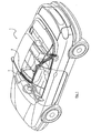
- the vehicle shown schematically and perspectively in FIG. 1 is provided with a folding top, generally designated 1, which, in the illustrated closed state, bears against a windshield frame 3 of the vehicle with a front roof part 2.
- the folding top has three mutually movable or foldable roof parts, namely the said front Roof part 2, a central roof part 4 and a rear roof part 6, and a rear window element 8.
- the folding top is stored in a rear-side convertible top compartment (not shown), which is covered with a folding top compartment lid 10 which can be swung backwards, as well as FIG shows.
- Fig. 2 shows (half-side) the folding top 1 in a movement phase shortly after opening or before closing the roof, the rear window element 8 is pivoted upward and the top compartment lid 10 is open.
- inclination sensors are arranged on different elements of the folding top or on this functionally assigned movable parts, namely a first inclination sensor 12a on the front roof part 2, a second inclination sensor 12b on the rear window element 8 and a third inclination sensor 12c on the top compartment cover 10.
- Another tilt sensor 12d is fixedly connected to the body of the vehicle to form a vehicle tilt reference signal.
- the central roof part 4 and / or the rear roof part 6 could also be provided with its own inclination sensor.
- tilt sensors could be fixed to selected linkage parts in order to provide position information relevant to the control of the folding roof.
- thermodynamic principle In a preferred embodiment of the invention commercial inclination sensors are used, which operate on a thermodynamic principle. In a closed gas volume, a convective gas flow is caused by a heating element, which aligns with the (instantaneous or effective) gravitational or acceleration field. Highly sensitive temperature-dependent resistance elements detect the instantaneous, surrounding gas temperature. Any movement of the sensor structure (tilt or acceleration) causes an imbalance in the resistive elements and a corresponding electrical signal that is evaluable by an electronic detection circuit.
- the inclination sensors in the example shown the inclination sensors 12a to 12c, detect their inclination angle (one or two-axis detection) with respect to the horizontal, the inclination sensor (12d) connected to the body compensating any inclinations of the vehicle.
- inclination sensors which operate on the thermodynamic principle are not subject to any mechanical wear since there are no moving parts. There are no leakage problems, because no mounting on rotary axes is required and thus no housing with mechanically movable, passing through parts are available. Furthermore, tilt sensors are arbitrarily attachable to freely selectable locations on roof or rod parts or links without constructive changes to the roof are required. A significant advantage is that a vehicle type independent use is possible, with no adjustment of vehicle parts is required.
- the sensors need only be roughly pre-adjusted, since a fine adjustment by means of software of an adaptive control device is possible, whereby a complete compensation of never completely avoidable concealment tolerances is possible.
Landscapes
- Engineering & Computer Science (AREA)
- Mechanical Engineering (AREA)
- Body Structure For Vehicles (AREA)
- Power-Operated Mechanisms For Wings (AREA)
- Electric Propulsion And Braking For Vehicles (AREA)
- Superstructure Of Vehicle (AREA)
- Seal Device For Vehicle (AREA)
- Air-Conditioning For Vehicles (AREA)
- Air Bags (AREA)
Description
- Die Erfindung betrifft ein Faltverdeck für ein Kraftfahrzeug mit den Merkmalen des oberbegriffs von Anspruch 1 und ein Fahrzeug mit solch einem Faltverdeck gemäß Anspruch 10.
- Bei einem Cabriolet-Fahrzeug mit einem Faltverdeck, worunter vorliegend ganz allgemein ein öffnungsfähiges Dach verstanden werden soll, welches von einer an einem Windschutzscheibenrahmen anliegenden, geschlossenen Position in einen beispielsweise unter einem Verdeckkastendeckel befindlichen Stauraum in eine geöffnete Ablagestellung verlagerbar ist, verändern die Dachteile bzw. die Teile des Dachgestänges während der Öffnungs- bzw. Schließbewegung ihre Lage relativ zueinander und relativ zur Karosserie. Insbesondere zur Optimierung der Steuerung der Öffnungs- und Schließfunktion des Dachs ist es erforderlich, die genauen Positionen der einzelnen oder bestimmter Dach- oder Gestängeelemente während der Bewegungsphase möglichst genau zu kennen.
- Aus der gattungsgemäßen EP 0550952 B1 ist ein Faltverdeck mit Drehpotentiometern zur Lagebestimmung während der Verdeckbewegung bekannt. Hierbei befindet sich jeweils ein Drehpotentiometer auf einer Drehachse von zwei relativ zueinander winkelbeweglichen Verdeck- bzw. Deckelteilen, so daß zu jedem Zeitpunkt der Verdeckbewegung die Lage des Dachs bestimmt werden und über den Antrieb regelnd auf die Dachablagebewegung eingewirkt werden kann.
- Diese Lösung ist in mehrfacher Hinsicht nachteilig. Zunächst einmal ist man bei der Anbringung der Drehpotentiometer konstruktiv örtlich auf Drehachsen beschränkt, wobei die Drehpotentiometer ein gegen Feuchtigkeit und Staub abgedichtetes Gehäuse benötigen. Als mechanische Bauteile sind die Drehpotentiometer Verschleiß und Alterung unterworfen. Ferner ist für jeden Fahrzeugtyp (unterschiedliche Anzahl und Winkelverstellbereiche der Drehachsen) eine eigene Konstruktion notwendig. Eine weitere Schwierigkeit ergibt sich dadurch, daß eine Anzahl von Drehpotentiometern trotz Serienfertigung nicht miteinander identisch sind, was wiederum durch Justiermaßnahmen ausgeglichen werden muß.
- Bekannt ist ferner die Verwendung von Endschaltern zur Erfassung der Endlage einer Bewegung bzw. Teilbewegung des Verdecks und der Dach- oder Gestängeelemente, wobei ein gravierender Nachteil einer solchen Lösung darin liegt, daß keinerlei Positionserfassung der Verdeckstellung während der Bewegungsphase des Dachs möglich ist. Auch ist die Anbringung von Mikroschaltern an Gestängeteilen (Anlenkung, Platzbedarf) nicht unproblematisch.
- Die Aufgabe der Erfindung besteht darin, ein gattungsgemäßes Faltverdeck dahingehend zu verbessern, daß eine Lagemessung einzelner an der Bewegung des Dachs beteiligter Teile unabhängig vom Einbauort der Lagemeßeinrichtung sowie universell für jeden Fahrzeugtyp möglich ist.
- Diese Aufgabe wird durch die Merkmale von Anspruch 1 gelöst.
- Vorzugsweise ist vorgesehen, daß die Neigungssensoren als ein- oder zweiachsige Neigungssensoren ausgebildet sind.
- Zweckmäßigerweise ist ein Neigungssensor der Karosserie zugeordnet. Es kann vorgesehen sein, daß in den Bewegungsablauf des Faltverdecks eingebundene bewegliche Fahrzeugteile, insbesondere Verdeckkastendeckel oder variable Verdeckwanne, mit einem Neigungssensor versehen sind.
- Bevorzugt sind die Neigungssensoren durch Kleben befestigt.
- Vorzugsweise ist vorgesehen, daß die Neigungssensoren nach einem thermodynamischen Prinzip arbeiten. Hierbei ist bevorzugt vorgesehen, daß die Neigungssensoren in einem abgeschlossenen Gasvolumen ein Heizelement und mindestens ein temperaturabhängiges Widerstandselement aufweisen.
- Das Faltverdeck kann einen motorischen Antrieb und eine mit den Neigungssensoren verbundene Antriebssteuerung aufweisen.
- Die Erfindung wird nachfolgend anhand eines Ausführungsbeispiels unter Bezugnahme auf eine Zeichnung erläutert, wobei
- Fig. 1 in einer perspektivischen, schematischen Darstellung ein Kraftfahrzeug mit einem Faltverdeck in geschlossener Position zeigt, und
- Fig. 2 die wesentlichen Komponenten des Faltverdecks des Fahrzeugs nach Fig. 1 zeigt.
- Das in Fig. 1 schematisch und perspektivisch dargestellte Fahrzeug ist mit einem im ganzen mit 1 bezeichneten Faltverdeck versehen, das im dargestellten geschlossenen Zustand mit einem vorderen Dachteil 2 an einem Windschutzscheibenrahmen 3 des Fahrzeugs anliegt. Das Faltverdeck weist drei zueinander bewegliche bzw. faltbare Dachteile auf, nämlich das genannte vordere Dachteil 2, ein mittleres Dachteil 4 und ein hinteres Dachteil 6, sowie ein Heckscheibenelement 8. Im geschlossenen Zustand wird das Faltverdeck in einem heckseitigen Verdeckkasten (nicht dargestellt) abgelegt, der mit einem nach hinten aufschwenkbaren Verdeckkastendeckel 10 abgedeckt ist, wie auch Fig. 2 zeigt.
- Fig. 2 zeigt (halbseitig) das Faltverdeck 1 in einer Bewegungsphase kurz nach dem Öffnen bzw. vor dem Schließen des Dachs, wobei das Heckscheibenelement 8 nach oben geschwenkt und der Verdeckkastendeckel 10 geöffnet ist. Wie Fig. 2 weiter zeigt, sind auf unterschiedlichen Elementen des Faltverdecks bzw. diesem funktionsmäßig zugeordneten beweglichen Teilen Neigungssensoren angeordnet, nämlich ein erster Neigungssensor 12a auf dem vorderen Dachteil 2, ein zweiter Neigungssensor 12b auf dem Heckscheibenelement 8 sowie ein dritter Neigungssensor 12c auf dem Verdeckkastendeckel 10. Ein weiterer Neigungssensor 12d ist fest mit der Karosserie des Fahrzeugs verbunden, um ein Referenzsignal für die Fahrzeugneigung zu bilden.
- Soweit zweckmäßig, könnte auch das mittlere Dachteil 4 und/oder das hintere Dachteil 6 mit einem eigenen Neigungssensor versehen sein. Zusätzlich oder alternativ zu den genannten Neigungssensoren an einzelnen Dachteilen bzw. Dachabschnitten könnten Neigungssensoren an ausgewählten Gestängeteilen fixiert sein, um für die Steuerung des Faltverdecks relevante Positionsinformationen zu liefern.
- In einer bevorzugten Ausführungsform der Erfindung werden handelsübliche Neigungssensoren eingesetzt, die nach einem thermodynamischen Prinzip arbeiten. In einem abgeschlossenen Gasvolumen wird durch ein Heizelement eine konvektive Gasströmung hervorgerufen, die sich am (momentanen bzw. effektiven) Gravitations- bzw. Beschleunigungsfeld ausrichtet. Hochsensible temperaturabhängige Widerstandselemente erfassen die momentane, sie umgebende Gastemperatur. Jede Bewegung der Sensorstruktur (Neigung oder Beschleunigung) bewirkt ein Ungleichgewicht in den Widerstandselementen und ein entsprechendes elektrisches Signal, das durch eine elektronische Erfassungsschaltung auswertbar ist.
- Die Neigungssensoren, im dargestellten Beispiel die Neigungssensoren 12a bis 12c, erfassen ihren Neigungswinkel (ein- oder zweiachsige Erfassung) gegenüber der Horizontalen, wobei der mit der Karosserie verbundene Neigungssensor (12d) etwaige Neigungen des Fahrzeugs kompensiert.
- Die erfindungsgemäße Erfassung der "absoluten" Lage einzelner Dachteile oder Gestängeelemente bzw. sonstiger beweglicher Teile mittels Neigungssensoren bringt im Vergleich mit den bekannten Lagemeßeinrichtungen (z.B. Potentiometer oder Endschalter) erhebliche Vorteile mit sich. Zunächst einmal sind Neigungssensoren, die nach dem thermodynamischen Prinzip arbeiten, keinerlei mechanischem Verschleiß unterworfen, da keine beweglichen Teile vorhanden sind. Es bestehen keinerlei Dichtigkeitsprobleme, da keine Montage an Drehachsen erforderlich ist und somit keine Gehäuse mit mechanisch bewegbaren, hindurchreichenden Teilen vorhanden sind. Ferner sind Neigungssensoren beliebig an frei wählbaren Orten an Dach- oder Gestängeteilen bzw. Lenkern anbringbar, ohne daß konstruktive Änderungen am Dach erforderlich sind. Ein wesentlicher Vorteil besteht darin, daß ein fahrzeugtypenunabhängiger Einsatz möglich ist, wobei keine Anpassung von Fahrzeugteilen erforderlich ist. Schließlich müssen die Sensoren nur grob vorjustiert werden, da eine Feinjustierung mittels einer Software eines lernfähigen Steuergeräts möglich ist, wodurch auch ein kompletter Ausgleich von nie ganz zu vermeidenden Verdecktoleranzen möglich wird. Insbesondere die geringe Größe von Neigungssensoren und die Möglichkeit, diese in einfachster Weise durch Kleben an Verdeckbauteilen anzubringen, eröffnen einen universellen Einsatz.
-
- 1
- Faltverdeck
- 2
- vorderes Dachteil
- 3
- Windschutzscheibenrahmen
- 4
- mittleres Dachteil
- 6
- hinteres Dachteil
- 8
- Heckscheibenelement
- 10
- Verdeckkastendeckel
- 12a - d
- Neigungssensoren
Claims (10)
- Faltverdeck (1) für ein Kraftfahrzeug,- mit mindestens einem Dachelement (2, 4, 6, 8), das relativ zu einer Karosserie des Kraftfahrzeugs bewegbar ist, und- mit einer Lagemesseinrichtung zum Erfassen der Position mindestens eines Dachelements über dessen Bewegungsbereich,- wobei die Lagemesseinrichtung mindestens zwei Lageerfassungsmittel (12a, 12b, 12c, 12d) aufweist,- von denen eines einem Dachelement (2, 4, 6, 8) und ein anderes entweder- einem anderen Dachelement (2, 4, 6, 8) oder- der Karosserie des Kraftfahrzeugs zugeordnet ist, dadurch gekennzeichnet, daß1. die Lageerfassungsmittel (12a, 12b, 12c, 12d) als Neigungssensoren (12a, 12b, 12c, 12d) ausgebildet sind,2. wobei einem Dachelement (2, 4, 6, 8) oder der Karosserie jeweils nur ein Neigungssensor (12a, 12b, 12c, 12d) zugeordnet ist, und3. die Neigungssensoren (12a, 12b, 12c) jeweils ihren Neigungswinkel gegenüber der Horizontalen erfassen, wenn der Neigungssensor einem Dachelement (2, 4, 6, 8) zugeordnet ist,4. bzw. ein Referenzsignal für die Fahrzeugneigung erfassen, wenn der Neigungssensor (12d) der Karosserie des Kraftfahrzeugs zugeordnet ist.
- Faltverdeck nach Anspruch 1, dadurch gekennzeichnet, daß die Neigungssensoren als ein- oder zweiachsige Neigungssensoren (12a, 12b, 12c, 12d) ausgebildet sind.
- Faltverdeck nach Anspruch 1 oder 2, dadurch gekennzeichnet, daß ein Neigungssensor (12d) der Karosserie zugeordnet ist.
- Faltverdeck nach einem der vorangehenden Ansprüche, dadurch gekennzeichnet, daß in den Bewegungsablauf des Faltverdecks eingebundene bewegliche Fahrzeugteile, insbesondere Verdeckkastendeckel (10) oder variable Verdeckwanne, mit einem Neigungssensor (12c) versehen sind.
- Faltverdeck nach einem der vorangehenden Ansprüche, dadurch gekennzeichnet, daß die Neigungssensoren (12a, 12b, 12c, 12d) durch Kleben befestigt sind.
- Faltverdeck nach einem der Ansprüche 2 bis 5, dadurch gekennzeichnet, daß die Neigungssensoren (12a, 12b, 12c, 12d) nach einem thermodynamischen Prinzip arbeiten.
- Faltverdeck nach Anspruch 6, dadurch gekennzeichnet, daß die Neigungssensoren in einem abgeschlossenen Gasvolumen ein Heizelement und mindestens ein temperaturabhängiges Widerstandselement aufweisen.
- Faltverdeck nach einem der vorangehenden Ansprüche, dadurch gekennzeichnet, daß das Faltverdeck einen motorischen Antrieb und eine mit den Neigungssensoren (12a, 12b, 12c, 12d) verbundene Antriebs-Steuereinrichtung aufweist.
- Faltverdeck nach einem der vorangehenden Ansprüche, dadurch gekennzeichnet, dass eine Feinjustierung der Neigungssensoren (12a, 12b, 12c, 12d) mittels einer Software eines lernfähigen Steuergeräts möglich ist.
- Fahrzeug mit einem Faltverdeck nach einem der vorangehenden Ansprüche.
Applications Claiming Priority (2)
| Application Number | Priority Date | Filing Date | Title |
|---|---|---|---|
| DE20117270U | 2001-10-20 | ||
| DE20117270U DE20117270U1 (de) | 2001-10-20 | 2001-10-20 | Faltverdeck für ein Kraftfahzeug |
Publications (2)
| Publication Number | Publication Date |
|---|---|
| EP1304247A1 EP1304247A1 (de) | 2003-04-23 |
| EP1304247B1 true EP1304247B1 (de) | 2006-05-31 |
Family
ID=7963121
Family Applications (1)
| Application Number | Title | Priority Date | Filing Date |
|---|---|---|---|
| EP02022076A Expired - Lifetime EP1304247B1 (de) | 2001-10-20 | 2002-10-02 | Faltverdeck für ein Kraftfahrzeug |
Country Status (3)
| Country | Link |
|---|---|
| EP (1) | EP1304247B1 (de) |
| AT (1) | ATE327914T1 (de) |
| DE (2) | DE20117270U1 (de) |
Cited By (1)
| Publication number | Priority date | Publication date | Assignee | Title |
|---|---|---|---|---|
| DE102007030496A1 (de) | 2007-06-30 | 2009-01-02 | Stabilus Gmbh | Kraftfahrzeug mit einer Laderaumschließklappe |
Families Citing this family (2)
| Publication number | Priority date | Publication date | Assignee | Title |
|---|---|---|---|---|
| DE10335535B4 (de) * | 2003-07-31 | 2007-10-31 | Edscha Cabrio-Dachsysteme Gmbh | Dach für ein Cabriolet-Fahrzeug |
| WO2007071208A1 (de) * | 2005-12-19 | 2007-06-28 | Webasto Ag | Fahrzeugdach und fahrzeug mit einem fahrzeugdach |
Family Cites Families (11)
| Publication number | Priority date | Publication date | Assignee | Title |
|---|---|---|---|---|
| US5225747A (en) * | 1992-01-06 | 1993-07-06 | Asc Incorporated | Single-button actuated self-correcting automatic convertible top |
| DE4232864A1 (de) | 1992-09-30 | 1994-03-31 | Thomson Brandt Gmbh | Drehwinkel-, Drehzahl- und Drehrichtungsmessung |
| DE19814460B4 (de) * | 1997-04-07 | 2010-01-07 | Marquardt Gmbh | System zur Signalübertragung |
| IT1293905B1 (it) * | 1997-05-28 | 1999-03-11 | Sgs Thomson Microelectronics | Sensore di posizione bidimensionale di tipo magnetico, in particolare per applicazioni automobilistiche. |
| DE19747326C2 (de) * | 1997-10-27 | 2003-08-28 | Bosch Gmbh Robert | Kraftfahrzeug-Faltdachsystem sowie Verfahren zum Betreiben eines Kraftfahrzeug-Faltdachsystems |
| AT405156B (de) | 1997-11-21 | 1999-06-25 | Hoerbiger Gmbh | Steuersystem für ein verdeck, insbesonders für fahrzeuge |
| DE19809061A1 (de) * | 1998-03-04 | 1999-09-09 | Porsche Ag | Verfahren zum Steuern eines zu öffnenden Daches mit einer Verschlußeinrichtung |
| JP3634990B2 (ja) | 1999-10-19 | 2005-03-30 | アイシン精機株式会社 | 位置検出装置 |
| DE19952590A1 (de) | 1999-11-02 | 2001-05-10 | Daimler Chrysler Ag | Verfahren zur Betätigung des Verdecks eines Kraftfahrzeugs |
| DE20016496U1 (de) | 2000-09-23 | 2001-08-23 | Wilhelm Karmann GmbH, 49084 Osnabrück | Vorrichtung zur Erfassung von Winkelstellungen von gegeneinander schwenkbeweglichen Teilen |
| DE10048517A1 (de) | 2000-09-29 | 2002-04-18 | Porsche Ag | Kraftfahrzeug mit automatisch betätigtem zu öffnenden Verdeck |
-
2001
- 2001-10-20 DE DE20117270U patent/DE20117270U1/de not_active Expired - Lifetime
-
2002
- 2002-10-02 AT AT02022076T patent/ATE327914T1/de not_active IP Right Cessation
- 2002-10-02 DE DE50206978T patent/DE50206978D1/de not_active Expired - Lifetime
- 2002-10-02 EP EP02022076A patent/EP1304247B1/de not_active Expired - Lifetime
Cited By (2)
| Publication number | Priority date | Publication date | Assignee | Title |
|---|---|---|---|---|
| DE102007030496A1 (de) | 2007-06-30 | 2009-01-02 | Stabilus Gmbh | Kraftfahrzeug mit einer Laderaumschließklappe |
| DE102007030496B4 (de) * | 2007-06-30 | 2012-04-26 | Stabilus Gmbh | Kraftfahrzeug mit einer Laderaumschließklappe |
Also Published As
| Publication number | Publication date |
|---|---|
| ATE327914T1 (de) | 2006-06-15 |
| DE20117270U1 (de) | 2002-01-10 |
| EP1304247A1 (de) | 2003-04-23 |
| DE50206978D1 (de) | 2006-07-06 |
Similar Documents
| Publication | Publication Date | Title |
|---|---|---|
| EP1815594B1 (de) | Schaltvorrichtung für ein kraftfahrzeug | |
| EP1308333B1 (de) | Ablegbares Fahrzeugdach für ein Cabriolet | |
| CN101460335B (zh) | 封闭遮盖板装置 | |
| US12083964B2 (en) | Rotatable display | |
| DE4017897C1 (de) | ||
| DE4024431A1 (de) | Geraet zur steuerung einer klimaanlage fuer ein kraftfahrzeug | |
| DE10014073B4 (de) | Sicherheitsgerät für motorbetriebene Fenster | |
| DE3607650A1 (de) | Vorrichtung zum einziehen der heckscheibe eines mit einem dachaufbau versehenen fahrzeuges | |
| EP0968100B1 (de) | Innenlichtmodul mit regensensor | |
| EP1556237B1 (de) | Kraftfahrzeug mit einem fahrbaren verdeck | |
| DE19807309A1 (de) | Instrumententafel | |
| DE102006043619A1 (de) | Bedieneinheit für eine Fahrzeugkomponente, insbesondere Klimasteuergerät für ein Fahrzeug | |
| EP1304247A1 (de) | Faltverdeck für ein Kraftfahrzeug | |
| DE4118393C2 (de) | Sonnenblende | |
| DE19609408A1 (de) | Armaturenbrett für ein Kraftfahrzeug | |
| EP1254800B1 (de) | Dachanordnung für ein Fahrzeug | |
| DE10251128B3 (de) | Anordnung eines Temperatursensors zur Ermittlung der Innenraumtemperatur | |
| EP1440218A1 (de) | Antrieb | |
| DE19644658A1 (de) | Außenspiegel für ein Fahrzeug | |
| DE3242242C2 (de) | Klappenmechanismus zum Öffnen und Schließen eines Luftleitkanales für Heiz- und Belüftungsanlagen von Kraftfahrzeugen | |
| DE102017115024A1 (de) | Antriebsanordnung für eine Klappe eines Kraftfahrzeugs | |
| DE4019690A1 (de) | Steuervorrichtung fuer fahrzeuge | |
| EP0325707B1 (de) | Kraftfahrzeug | |
| DE102006008544B4 (de) | Waage | |
| EP1834058A2 (de) | Verriegelungsvorrichtung für ein fahrzeugteil |
Legal Events
| Date | Code | Title | Description |
|---|---|---|---|
| PUAI | Public reference made under article 153(3) epc to a published international application that has entered the european phase |
Free format text: ORIGINAL CODE: 0009012 |
|
| AK | Designated contracting states |
Designated state(s): AT BE BG CH CY CZ DE DK EE ES FI FR GB GR IE IT LI LU MC NL PT SE SK TR |
|
| AX | Request for extension of the european patent |
Extension state: AL LT LV MK RO SI |
|
| RIN1 | Information on inventor provided before grant (corrected) |
Inventor name: ESSELMANN, CHRISTOF Inventor name: RETHSCHULTE, DIETER Inventor name: GUTENDORF, PETER |
|
| 17P | Request for examination filed |
Effective date: 20030519 |
|
| 17Q | First examination report despatched |
Effective date: 20030701 |
|
| AKX | Designation fees paid |
Designated state(s): AT BE BG CH CY CZ DE DK EE ES FI FR GB GR IE IT LI LU MC NL PT SE SK TR |
|
| GRAP | Despatch of communication of intention to grant a patent |
Free format text: ORIGINAL CODE: EPIDOSNIGR1 |
|
| GRAS | Grant fee paid |
Free format text: ORIGINAL CODE: EPIDOSNIGR3 |
|
| GRAA | (expected) grant |
Free format text: ORIGINAL CODE: 0009210 |
|
| AK | Designated contracting states |
Kind code of ref document: B1 Designated state(s): AT BE BG CH CY CZ DE DK EE ES FI FR GB GR IE IT LI LU MC NL PT SE SK TR |
|
| PG25 | Lapsed in a contracting state [announced via postgrant information from national office to epo] |
Ref country code: IT Free format text: LAPSE BECAUSE OF FAILURE TO SUBMIT A TRANSLATION OF THE DESCRIPTION OR TO PAY THE FEE WITHIN THE PRESCRIBED TIME-LIMIT;WARNING: LAPSES OF ITALIAN PATENTS WITH EFFECTIVE DATE BEFORE 2007 MAY HAVE OCCURRED AT ANY TIME BEFORE 2007. THE CORRECT EFFECTIVE DATE MAY BE DIFFERENT FROM THE ONE RECORDED. Effective date: 20060531 Ref country code: CZ Free format text: LAPSE BECAUSE OF FAILURE TO SUBMIT A TRANSLATION OF THE DESCRIPTION OR TO PAY THE FEE WITHIN THE PRESCRIBED TIME-LIMIT Effective date: 20060531 Ref country code: SK Free format text: LAPSE BECAUSE OF FAILURE TO SUBMIT A TRANSLATION OF THE DESCRIPTION OR TO PAY THE FEE WITHIN THE PRESCRIBED TIME-LIMIT Effective date: 20060531 Ref country code: FI Free format text: LAPSE BECAUSE OF FAILURE TO SUBMIT A TRANSLATION OF THE DESCRIPTION OR TO PAY THE FEE WITHIN THE PRESCRIBED TIME-LIMIT Effective date: 20060531 Ref country code: NL Free format text: LAPSE BECAUSE OF FAILURE TO SUBMIT A TRANSLATION OF THE DESCRIPTION OR TO PAY THE FEE WITHIN THE PRESCRIBED TIME-LIMIT Effective date: 20060531 Ref country code: IE Free format text: LAPSE BECAUSE OF FAILURE TO SUBMIT A TRANSLATION OF THE DESCRIPTION OR TO PAY THE FEE WITHIN THE PRESCRIBED TIME-LIMIT Effective date: 20060531 |
|
| REG | Reference to a national code |
Ref country code: GB Ref legal event code: FG4D Free format text: NOT ENGLISH Ref country code: CH Ref legal event code: EP |
|
| REG | Reference to a national code |
Ref country code: IE Ref legal event code: FG4D Free format text: LANGUAGE OF EP DOCUMENT: GERMAN |
|
| REF | Corresponds to: |
Ref document number: 50206978 Country of ref document: DE Date of ref document: 20060706 Kind code of ref document: P |
|
| PG25 | Lapsed in a contracting state [announced via postgrant information from national office to epo] |
Ref country code: SE Free format text: LAPSE BECAUSE OF FAILURE TO SUBMIT A TRANSLATION OF THE DESCRIPTION OR TO PAY THE FEE WITHIN THE PRESCRIBED TIME-LIMIT Effective date: 20060831 Ref country code: DK Free format text: LAPSE BECAUSE OF FAILURE TO SUBMIT A TRANSLATION OF THE DESCRIPTION OR TO PAY THE FEE WITHIN THE PRESCRIBED TIME-LIMIT Effective date: 20060831 |
|
| PG25 | Lapsed in a contracting state [announced via postgrant information from national office to epo] |
Ref country code: ES Free format text: LAPSE BECAUSE OF FAILURE TO SUBMIT A TRANSLATION OF THE DESCRIPTION OR TO PAY THE FEE WITHIN THE PRESCRIBED TIME-LIMIT Effective date: 20060911 |
|
| GBT | Gb: translation of ep patent filed (gb section 77(6)(a)/1977) |
Effective date: 20060918 |
|
| PG25 | Lapsed in a contracting state [announced via postgrant information from national office to epo] |
Ref country code: PT Free format text: LAPSE BECAUSE OF FAILURE TO SUBMIT A TRANSLATION OF THE DESCRIPTION OR TO PAY THE FEE WITHIN THE PRESCRIBED TIME-LIMIT Effective date: 20061031 Ref country code: MC Free format text: LAPSE BECAUSE OF NON-PAYMENT OF DUE FEES Effective date: 20061031 Ref country code: LI Free format text: LAPSE BECAUSE OF NON-PAYMENT OF DUE FEES Effective date: 20061031 Ref country code: CH Free format text: LAPSE BECAUSE OF NON-PAYMENT OF DUE FEES Effective date: 20061031 |
|
| NLV1 | Nl: lapsed or annulled due to failure to fulfill the requirements of art. 29p and 29m of the patents act | ||
| ET | Fr: translation filed | ||
| REG | Reference to a national code |
Ref country code: IE Ref legal event code: FD4D |
|
| PLBE | No opposition filed within time limit |
Free format text: ORIGINAL CODE: 0009261 |
|
| STAA | Information on the status of an ep patent application or granted ep patent |
Free format text: STATUS: NO OPPOSITION FILED WITHIN TIME LIMIT |
|
| 26N | No opposition filed |
Effective date: 20070301 |
|
| REG | Reference to a national code |
Ref country code: CH Ref legal event code: PL |
|
| BERE | Be: lapsed |
Owner name: WILHELM KARMANN G.M.B.H. Effective date: 20061031 |
|
| PG25 | Lapsed in a contracting state [announced via postgrant information from national office to epo] |
Ref country code: AT Free format text: LAPSE BECAUSE OF NON-PAYMENT OF DUE FEES Effective date: 20061002 |
|
| PG25 | Lapsed in a contracting state [announced via postgrant information from national office to epo] |
Ref country code: GR Free format text: LAPSE BECAUSE OF FAILURE TO SUBMIT A TRANSLATION OF THE DESCRIPTION OR TO PAY THE FEE WITHIN THE PRESCRIBED TIME-LIMIT Effective date: 20060901 |
|
| PG25 | Lapsed in a contracting state [announced via postgrant information from national office to epo] |
Ref country code: EE Free format text: LAPSE BECAUSE OF FAILURE TO SUBMIT A TRANSLATION OF THE DESCRIPTION OR TO PAY THE FEE WITHIN THE PRESCRIBED TIME-LIMIT Effective date: 20060531 Ref country code: BG Free format text: LAPSE BECAUSE OF FAILURE TO SUBMIT A TRANSLATION OF THE DESCRIPTION OR TO PAY THE FEE WITHIN THE PRESCRIBED TIME-LIMIT Effective date: 20060831 |
|
| PG25 | Lapsed in a contracting state [announced via postgrant information from national office to epo] |
Ref country code: TR Free format text: LAPSE BECAUSE OF FAILURE TO SUBMIT A TRANSLATION OF THE DESCRIPTION OR TO PAY THE FEE WITHIN THE PRESCRIBED TIME-LIMIT Effective date: 20060531 Ref country code: LU Free format text: LAPSE BECAUSE OF NON-PAYMENT OF DUE FEES Effective date: 20061002 |
|
| PG25 | Lapsed in a contracting state [announced via postgrant information from national office to epo] |
Ref country code: CY Free format text: LAPSE BECAUSE OF FAILURE TO SUBMIT A TRANSLATION OF THE DESCRIPTION OR TO PAY THE FEE WITHIN THE PRESCRIBED TIME-LIMIT Effective date: 20060531 |
|
| PG25 | Lapsed in a contracting state [announced via postgrant information from national office to epo] |
Ref country code: BE Free format text: LAPSE BECAUSE OF FAILURE TO SUBMIT A TRANSLATION OF THE DESCRIPTION OR TO PAY THE FEE WITHIN THE PRESCRIBED TIME-LIMIT Effective date: 20061031 |
|
| PGFP | Annual fee paid to national office [announced via postgrant information from national office to epo] |
Ref country code: IT Payment date: 20101016 Year of fee payment: 9 |
|
| PG25 | Lapsed in a contracting state [announced via postgrant information from national office to epo] |
Ref country code: IT Free format text: LAPSE BECAUSE OF NON-PAYMENT OF DUE FEES Effective date: 20111002 |
|
| REG | Reference to a national code |
Ref country code: GB Ref legal event code: 732E Free format text: REGISTERED BETWEEN 20131114 AND 20131120 |
|
| REG | Reference to a national code |
Ref country code: FR Ref legal event code: TP Owner name: VALMET AUTOMOTIVE OY, FI Effective date: 20131209 |
|
| REG | Reference to a national code |
Ref country code: DE Ref legal event code: R081 Ref document number: 50206978 Country of ref document: DE Owner name: VALMET AUTOMOTIVE OY, FI Free format text: FORMER OWNER: WILHELM KARMANN GMBH, 49084 OSNABRUECK, DE Effective date: 20131128 Ref country code: DE Ref legal event code: R082 Ref document number: 50206978 Country of ref document: DE Representative=s name: KRONTHALER, SCHMIDT & COLL. PATENTANWALTSKANZL, DE Effective date: 20131128 |
|
| PGFP | Annual fee paid to national office [announced via postgrant information from national office to epo] |
Ref country code: FR Payment date: 20131018 Year of fee payment: 12 Ref country code: GB Payment date: 20131022 Year of fee payment: 12 |
|
| PGFP | Annual fee paid to national office [announced via postgrant information from national office to epo] |
Ref country code: DE Payment date: 20141120 Year of fee payment: 13 |
|
| GBPC | Gb: european patent ceased through non-payment of renewal fee |
Effective date: 20141002 |
|
| PG25 | Lapsed in a contracting state [announced via postgrant information from national office to epo] |
Ref country code: GB Free format text: LAPSE BECAUSE OF NON-PAYMENT OF DUE FEES Effective date: 20141002 |
|
| REG | Reference to a national code |
Ref country code: FR Ref legal event code: ST Effective date: 20150630 |
|
| PG25 | Lapsed in a contracting state [announced via postgrant information from national office to epo] |
Ref country code: FR Free format text: LAPSE BECAUSE OF NON-PAYMENT OF DUE FEES Effective date: 20141031 |
|
| REG | Reference to a national code |
Ref country code: DE Ref legal event code: R119 Ref document number: 50206978 Country of ref document: DE |
|
| PG25 | Lapsed in a contracting state [announced via postgrant information from national office to epo] |
Ref country code: DE Free format text: LAPSE BECAUSE OF NON-PAYMENT OF DUE FEES Effective date: 20160503 |