EP1303832B1 - Imagerie de milieux de diffusion au moyen de valeurs de detection relatives - Google Patents
Imagerie de milieux de diffusion au moyen de valeurs de detection relatives Download PDFInfo
- Publication number
- EP1303832B1 EP1303832B1 EP00963433.8A EP00963433A EP1303832B1 EP 1303832 B1 EP1303832 B1 EP 1303832B1 EP 00963433 A EP00963433 A EP 00963433A EP 1303832 B1 EP1303832 B1 EP 1303832B1
- Authority
- EP
- European Patent Office
- Prior art keywords
- vector
- medium
- measured data
- target
- source
- Prior art date
- Legal status (The legal status is an assumption and is not a legal conclusion. Google has not performed a legal analysis and makes no representation as to the accuracy of the status listed.)
- Expired - Lifetime
Links
Images


Classifications
-
- G—PHYSICS
- G01—MEASURING; TESTING
- G01N—INVESTIGATING OR ANALYSING MATERIALS BY DETERMINING THEIR CHEMICAL OR PHYSICAL PROPERTIES
- G01N21/00—Investigating or analysing materials by the use of optical means, i.e. using sub-millimetre waves, infrared, visible or ultraviolet light
- G01N21/17—Systems in which incident light is modified in accordance with the properties of the material investigated
- G01N21/47—Scattering, i.e. diffuse reflection
- G01N21/49—Scattering, i.e. diffuse reflection within a body or fluid
-
- G—PHYSICS
- G01—MEASURING; TESTING
- G01N—INVESTIGATING OR ANALYSING MATERIALS BY DETERMINING THEIR CHEMICAL OR PHYSICAL PROPERTIES
- G01N21/00—Investigating or analysing materials by the use of optical means, i.e. using sub-millimetre waves, infrared, visible or ultraviolet light
- G01N21/17—Systems in which incident light is modified in accordance with the properties of the material investigated
- G01N21/47—Scattering, i.e. diffuse reflection
- G01N21/4795—Scattering, i.e. diffuse reflection spatially resolved investigating of object in scattering medium
Definitions
- the invention relates generally to imaging in a scattering medium, and more particularly, to a method using a novel modification to the perturbation formulation of the radiation transport inverse problem to determine relative changes in the absorption and/or scattering properties of the medium based on relative changes in measured energy.
- a system for imaging based on scattered energy detection includes a source for directing energy into a target medium and a plurality of detectors for measuring the intensity of the scattered energy exiting the target medium at various locations with respect to the source. Based on the measured intensity of the energy exiting the target medium, it is possible to reconstruct an image representing the cross-sectional scattering and/or absorption properties of the target. Exemplary methods and systems are disclosed in Barbour et al., U.S. Patent No.
- Imaging techniques based on the detection of scattered energy are capable of measuring the internal absorption, scattering and other properties of a medium using sources whose penetrating energy is highly scattered by the medium. Accordingly, these techniques permit the use of wavelengths and types of energy not suitable for familiar transmission imaging techniques. Thus they have great potential for detecting properties of media that are not accessible to traditional energy sources used for transmission imaging techniques. For example, one flourishing application of imaging in scattering media is in the field of optical tomography. Optical tomography permits the use of near infrared energy as an imaging source. Near infrared energy is highly scattered by human tissue and is therefore an unsuitable source for transmission imaging in human tissue. However, these properties make it a superior imaging source for scattering imaging techniques. The ability to use near infrared energy as an imaging source is of particular interest in clinical medicine because it is exceptionally responsive to blood volume and blood oxygenation levels, thus having great potential for detecting cardiovascular disease, tumors and other disease states.
- a common approach for the reconstruction of an image of the cross-sectional properties of a scattering medium is to solve a perturbation equation based on the radiation transport equation.
- the radiation transport equation is a mathematical expression describing the propagation of energy through a scattering medium.
- the perturbation formulation relates the difference between coefficient values of the true target and a specified reference medium, weighted by a proportionality coefficient whose value depends on, among other things, the source/detector configuration and the optical properties of the medium.
- the operator referred to as the weight matrix, has coefficient values that physically represent the fractional change in light intensity at the surface caused by an incremental change in the optical properties at a specified point in the medium. Mathematically this is represented by the partial differential operator ⁇ u i / ⁇ x j , where i is related to the i th source/detector pairs at the surface of the medium, and j to the j th pixel or element in the medium.
- An accurate reference is one that closely matches the external geometry of the target medium, has the same size, nearly the same internal composition, and for which the locations of the measuring probes and their efficiency coincide well with those used in the actual measurements. While such conditions may be easily met in numerical and perhaps laboratory phantom studies, they represent a much greater challenge in the case of tissue studies. Confounding factors include the plasticity of tissue (it deforms upon probe contact), its mainly arbitrary external geometry and internal composition and the considerable uncertainty stemming from the expected variable coupling efficiency of light at the tissue surface. The influence of these uncertainties can be appreciated when it is recognized that the input data vector for the standard perturbation formulation (i.e ., Eq. (1)) is actually the difference between a measured and a computed quantity. This vector contains information regarding the subsurface properties of the target medium that, in principle, can be extracted provided an accurate reference medium is available.
- Eq. (1) the standard perturbation formulation
- a second concern stems from the underlying physics of energy transport in highly scattering media.
- One effect of scattering is to greatly increase the pathlength of the propagating energy.
- Small changes in the estimated absorption or scattering properties of the medium can, depending on the distance separating the source and detector, greatly influence the density of emerging energy.
- This consideration has important implications regarding the required accuracy by which the reference medium must be specified.
- the reference medium serves to provide estimates of the predicted energy density as well as to provide the needed weight functions that serve as the imaging operators.
- the difficulty is that the computed reference intensity values are extremely dependent on the optical coefficient values of the reference medium. Significantly, this dependence is a nonlinear function of the distance between source and detector.
- I measurement represents the measured intensity of the selected light path in the turbid medium and the calibration medium
- I cal represents the measured intensity of the selected light path in the calibration medium
- a 1 represents the direction coefficient of the reference line
- r represent the length of the selected light path.
- I cal corresponds to "a third vector of computed detector readings corresponding to a reference medium”.
- the document discloses only one of a first vector or a second vector.
- Document US 5 903 357 discloses that a single detector reading for a test and a detector reading for a reference media are employed as well. Additionally, the document discloses the generation of a quantity ⁇ (r d ), which is given by ⁇ 0 (r d ) - ⁇ (r d ). Col. 8, lines 6 - 7 states that ⁇ 0 is given by formula (1). Col. 5, lines 18 - 25 shows that ⁇ 0 is a solution of a diffusion equation "in a homogeneous medium". Thus, ⁇ 0 is a vector that represents "reference data that is indicative of energy emerging from the reference medium", and as such, corresponds to a third vector, but does not correspond to a first vector or a second vector. The document does not disclose a first vector and a second vector.
- the present invention satisfies these needs by providing a method for generating an image of a scattering medium using normalized relative measured intensity values a perturbation formulation based on the radiation transport equation.
- the method comprises generating a first data vector of measured data from a target and a second vector of measured data from a target, normalizing the first and second vectors of measured data and solving a modified perturbation equation for the unknown optical properties of a target medium.
- the first and second vectors of measured data are measures of energy emerging from the target.
- first and second sets of measured data from the same target, wherein the first set of measured data is a set of data measured at an instant in time and the second set of measured data is a time average mean of a plurality of first sets of measured data.
- the modified perturbation equation is a modified Rytov approximation.
- the modified perturbation equation is a modified Born approximation.
- Imaging in a scattering medium relates to the methods and techniques of image the internal properties of a medium based on the detection of scattered energy.
- the typical process for imaging of a scattering medium comprises: (1) selecting a reference medium having known boundary conditions and optical properties which are substantially similar to those of the intended target; (2) determining a weight matrix and an intensity of emerging energy exiting the reference medium at each of a plurality of source points for each of a plurality of detectors located around the reference medium boundary, the determination being made by either actual measurements or solution of the radiation transport equation; (3) measuring actual emerging energy intensities for corresponding source and detector points on a target medium; and (4) solving the perturbation equation for the optical properties of the target based on the measured intensities of energy emerging from the target.
- the present invention describes an improved methodology for imaging of a scattering medium using a modified form of the standard perturbation equation.
- the inventive modification of the standard perturbation equation is capable of (1) reducing the sensitivity of the perturbation equation to differences between the reference medium and target medium, (2) producing solutions to the perturbation equation having physical units, and (3) reducing the effect of variable detector efficiencies without the need for absolute calibration, while at the same time preserving the ability to compute recursive solutions.
- the described invention provides remarkable improvement in the quality of image reconstruction.
- the method of the present invention is applicable to known static imaging techniques it is instrumental in the realization of practical dynamic imaging of highly scattering media.
- the first element is the development of a fast, parallel, multi-channel acquisition system that employs geometrically adaptive measuring heads. This system is described briefly below and in further detail in the copending Barbour 4147PC1 application.
- the second element is to evaluate the acquired tomographic data using the modified perturbation methods of the present invention.
- the third element is to collect a time series of data and subject either the time series of data or a time series of reconstructed images from the data to analysis using various linear and nonlinear time-series analysis methods to extract dynamic information and isolated dynamic information. These methods are described in detail in the copending Barbour 4147PC2 application.
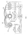
- FIG. 1 A schematic illustration of an exemplary system is shown in FIG. 1 .
- This system includes a computer 102, sources 104, 106, a source demultiplexer 108, an imaging head 110, detectors 112 and a data acquisition board 114.
- a target 116 placed in the imaging head 110 is exposed to optical energy from sources 104, 106.
- the optical energy originating from sources 104, 106 is combined by beam splitter 118 and is delivered to source demultiplexer 108.
- the source demultiplexer 108 is controlled by computer 102 to direct the optical energy to source fibers 120 sequentially.
- Each source fiber 120 carries the optical energy from the demultiplexer 108 to the imaging head 110, where the optical energy is directed into the target 116.
- the imaging head 110 contains a plurality of source fibers 120 and detector fibers 122 for transmitting and receiving light energy, respectively.
- Each source fiber 120 forms a source-detector pair with each detector fiber 122 in the imaging head 110 to create a plurality of source-detector pairs.
- the optical energy entering the target 116 at one location is scattered and may emerge at any location around the target 116.
- the emerging optical energy is collected by detector fibers 122 mounted in the imaging head 110.
- the detector fibers 122 carry the emerging energy to detectors 112, such as photodiodes or a CCD array, that measure the intensity of the optical energy and deliver a corresponding signal to a data acquisition board 114.
- detectors 112 such as photodiodes or a CCD array
- the data acquisition board 114 delivers the data to computer 102.
- This imaging process is repeated so as to deliver optical energy to each of the source fibers sequentially, a measurement being obtained for detected emerging energy at each detector for each emitting source fiber.
- This process may continue over a period of time with the computer 102 storing the data for reconstruction of one or more images.
- the system may include two or more imaging heads for comparing one target to another.
- the computer 102 reconstructs an image representative of the internal optical properties of the target by solving a perturbation equation. It will be appreciated by those skilled in the art that more than one computer can be used to increase data handling and image processing speeds.
- reconstruction of a cross section image of the absorption and/or scattering properties of the target medium is based on the solution of a perturbation formulation of the radiation transport equation.
- the perturbation method assumes that the composition of the unknown target medium deviates only by a small amount from a known reference medium. This reduces a highly non-linear problem to one that is linear with respect to the difference in absorption and scattering properties between the target medium under investigation and the reference medium.
- W is the weight matrix describing the influence that each volume element ("voxel") of the reference medium has on energy traveling from each source to each detector, for all source-detector pairs.
- the volume elements are formed by dividing a slice of the reference medium into an imaginary grid of contiguous, non-overlapping pieces.
- the weight matrix contains the first order partial derivatives of the detector responses with respect to the optical coefficients of each volume element of the reference medium.
- ⁇ x is the vector of differences between the known optical properties (e.g., absorption and scattering coefficients) of each volume element of the reference medium and the corresponding unknown optical properties of each volume element of the target medium.
- I r is the computed detector reading corresponding to a source-detector pair of a selected reference medium
- I and I 0 represent two data measurements for a corresponding source-detector pair on one or more targets (e.g., background vs. target, or time-averaged mean vs. a specific time point, etc.).
- ⁇ I r therefore represents a relative difference between two sets of measured data that is then mapped onto a reference medium. Careful examination reveals that this modification has important attributes that limit the effects of modeling errors and minimize ill-conditioning of the inverse problem while retaining the correct units in the solution.
- the perturbation equation is generated for a reference medium having boundary conditions and optical properties substantially similar to the target.
- the perturbation equation models the energy propagation, e.g. light, in the reference medium as a diffusion process.
- u(r) is the photon density at position r
- r s is the position of a DC point source
- D(r) and ⁇ a (r) are the position-dependent diffusion and absorption coefficients, respectively.
- the photon density values at the detectors i.e., the calculated energy intensity emerging from the reference medium at each detector, were computed by applying Dirichlet boundary conditions on an extrapolated boundary.
- sources and detectors for the reference are positioned 1 to 2 transport mean free pathlengths within the boundary of the reference medium.
- Solutions to the diffusion equation may be computed by any known means, such as by the KASKADE adaptive finite element method.
- R. Beck, R. Erdmann and R. Roitzsch "Kaskade 3.0 - An object-oriented adaptive finite element code," Technical report TR 95-4, Konrad-Zuse-Zentrum fur Informationstechnik, Berlin (1995 ).
- This is a publicly available code suitable for the solution of partial differential equations in one, two or three dimensions using adaptive finite element techniques.
- the code can be readily modified to permit solutions to the diffusion equation using a point source.
- Mesh generation may be by any known method, such as the Delaunay tessellation algorithm originally proposed by Watson. D. F. Watson, "Computing the n-dimensional Delaunay tessellation with applications to Voronoi polytopes", Computer Journal, 24, 167-172 (1981 ).
- the perturbation equation is specific to the boundary conditions and optical properties of the reference medium, including the orientation of the source-detector pairs in relation to one another and the reference medium. These conditions and properties are preferably nearly identical to the target.
- the perturbation equation was generated based on an imaging system having six sources and eighteen detectors per source (108 source-detector pairs) with the sources equally spaced at 60 degree intervals around the boundary of the medium and the detectors equally spaced at 20 degree intervals.
- a weight matrix rescaling (WMR) technique may be used to improve the ill-conditioning of the weight matrix.
- the effect of rescaling the weight matrix is to make it more uniform.
- Two rescaling criteria can be applied for this purpose: (1) rescaling the maximum of each column to 1; or (2) rescaling the average of each column to 1.
- criterion 1 was applied for image recovery.
- the solution to the modified perturbation equation provides a relative measure of the difference between the cross-sectional optical properties of a target during the first and second measurements I and I 0 .
- the values from this solution are used to generate cross-sectional images representative of the target's internal optical properties.
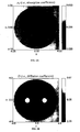
- FIGS. 2A and 2B show the cross-sectional geometry and absorption ( FIG. 2A ) and diffusion ( FIG. 2B ) coefficient profiles of the target medium explored.
- the target medium is 8cm in diameter and has two included objects each 1 cm in diameter and separated by 3 cm symmetrically about the center of a homogeneous background medium.
- Optical properties of the background and included objects are 0.04 and 0.02 cm -1 for ⁇ a (absorption coefficient), and 10 and 5 cm -1 for ⁇ s (scattering coefficient), respectively.
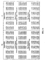
- the table of FIG. 3 lists the various test cases explored.
- the symbol “V” indicates that the parameter was varied, “C” indicates that the parameter was held constant, and " l " indicates that the parameter was not considered.
- the test cases allowed at least partial isolation of the effect of variations in each of the input parameters on the resultant image for different reconstruction schemes and perturbation formulations. This testing permitted exploration of the dependence of ill-conditioning on the different input parameters that influence the accuracy and stability of the image reconstruction.
- Test cases 1 and 2 examined the general case where the reference medium is based only on an estimate of the background optical properties of the target medium. The estimated properties were varied over a broad range, ranging from 0.0 cm -1 to 0.3 cm -1 in ⁇ a , and from 3 cm -1 to 30 cm -1 in ⁇ s . For purposes of comparison, test cases 3 through 7 explored the dependence of image quality on the varied parameters using the standard perturbation formulation.
- Test cases 3 and 4 mainly mirror conditions explored in cases 1 and 2 with the exceptions that the standard perturbation formulation was evaluated, and a narrower range of coefficient values was considered for the reference medium.
- the general case is also considered where only an estimate of the background optical properties of the target medium is available.
- the range of values for the optical properties explored were from 0.02 cm -1 to 0.08 cm -1 in ⁇ a , and from 5 cm -1 to 15 cm -1 in ⁇ s .
- Cases 5 and 6 consider the special situation where prior knowledge of the background properties of the target medium is known.
- the parameters varied were W r and I r , referred to as W b and I b , respectively.
- the range of optical properties varied for test 5 is same as in case 1.
- the range of optical properties varied is the same as in case 3.
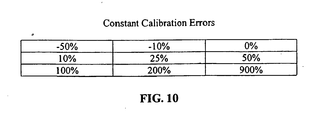
- Test case 7 explores the effect of a constant calibration error in measurement, and assumes prior knowledge of the background properties of the target medium.
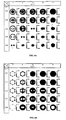
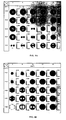
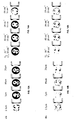
- FIGS. 4 through 9 illustrates the influence that the varied parameters listed in FIG. 3 have on the reconstruction results derived from a first-order Born approximation using the standard and modified perturbation formulations.
- the results presented are listed in a matrix format.
- the value of the absorption and scattering coefficient for the reference medium is fixed for each row and column, respectively. Varied is the value of these parameters along the orthogonal direction. Shown in the figures are the reconstruction profiles for all test cases explored except case 4, whose findings are reported in the text.
- FIGS. 4 and 5 show the quality of reconstructed images obtained using equation (3).
- FIGS. 4A and 5A illustrate the computed absorption maps
- FIGS. 4B and 5B show the computed diffusion maps.
- these findings illustrate that qualitatively accurate results, revealing the two-object structure, are obtained over a broad range of values for the selected reference medium. Artifact dominated results are limited to cases in the lower right corner of the matrix. These correspond to those reference media having absorption and scattering coefficient values significantly greater than the background of the target medium. Quantitative analysis of these results is presented in the next section. Comparison of images shown in FIGS.
- the matrix rescaling method is capable of providing a higher resolution image, though over a reduced range of values for the reference medium.
- comparison of results reveals that the matrix rescaling method yields only artifacts in the absorption map for non-absorbing reference media, while under the same conditions the diffusion coefficient maps reveal two completely resolved objects.
- both coefficient maps reveal the presence of the included objects, though with reduced edge resolution and more artifacts in the diffusion map.
- the added improvement using matrix rescaling is achieved under the limiting conditions of a range constraint (positive for D and negative for ⁇ a ).
- FIG. 6 Shown in FIG. 6 are results from case 3 evaluated using equation (1). Compared to results shown in FIGS. 4 and 5 , a more limited range of values of optical properties for the reference medium were examined, since outside of this range, only artifact was recovered. Even within the explored range, significant instability was observed for relatively small variations in the reference medium. This sensitivity indicates a state of ill-conditioning that is alleviated using the modified perturbation formulation (equation 3). Not shown are results from case 4 using the matrix rescaling method. In case 4, even greater instability was observed than in the case using CGD only.
- the parameters varied in the above figures include both the computed reference intensity and the weight matrix. This is the general case where both quantities can only be estimated and are computed from a specified reference medium.
- Results shown in FIGS. 7 through 9 explore the special cases where errors occur only in one parameter.
- Data in FIG. 7 illustrates the influence of errors in the estimated weight matrix. Assumed is prior knowledge of the reference detector intensity values for the background medium. In practice this would correspond to situations where a measurement was made in the presence and absence of an included object. Inspection reveals that qualitatively accurate results are obtained over a significantly broader range of reference values than those presented in FIG. 7 . This finding suggests that the principal origin of the ill-conditioning of the inverse problem is associated with errors in the estimated reference intensity.
- Results shown in FIG. 8 explore this possibility directly. In this situation, we assume the unlikely case where accurate prior knowledge of the weight matrix for the target medium is available. Comparison of the results in FIG. 8 to the results in FIG. 6 illustrates some improvement in the range of reference media yielding qualitatively accurate results. However, this range is small compared to the situations tested in FIG. 8 for the standard perturbation formulation and for the modified perturbation formulation in FIGS. 4 and 5 .
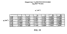
- Results shown in FIGS. 11 and 12 are the corresponding values computed from data shown in FIGS. 4 and 5 .
- the format of the data is the same as in FIG. 4 (i.e., data in the rows are derived for a fixed value of absorption, while column data is derived for a fixed value of scattering).
- FIGS. 13 and 14 Experimental verification demonstrating that the modified perturbation formulation is capable of resolving internal structure of a dense scattering medium is given in FIGS. 13 and 14 .
- Tomographic measurements were performed at 780 nm using the IRIS imaging system previously described.
- IRIS-OPTIsoanner a general-purpose optical tomographic imaging system.
- the target medium was a latex laboratory glove filled with 2% (v/v) Intralipid suspended from a holder in a pendant position. Added to the glove were two 1 cm diameter plastic tubes filled with varying concentrations of hemoglobin (Hb) in the amount of 5 ⁇ m, 10 ⁇ m, 20 ⁇ m, and 40 ⁇ m. A cross section of the phantom set-up is shown in FIG. 15 . The pass-through diameter of the IRIS imaging head was closed until gentle contact with the glove was achieved. The diameter of the glove in the measurement plane was 6.7 cm. Above and below this plane, the glove assumed an arbitrary geometry. Tomographic measurements were performed using the same measurement geometry described for the numerical studies. Optical measurements were performed in the presence and absence of the included objects from which the relative intensity values were derived.
- Hb hemoglobin
- the resultant data vectors were then evaluated by equation (3) using a regularized CGD method without weight matrix rescaling.
- the coefficient values for the reference medium used were varied from 0.01 to 0.04 cm -1 in ⁇ a and 10 to 20 cm -1 in ⁇ s .
- the present invention describes and evaluates a new formulation for the inverse problem for imaging in highly scattering media.
- Motivating this development has been an appreciation of the expected limits imposed by practical measurements, especially as it relates to the dependence of image accuracy on instrument calibration and the ability to specify an accurate reference medium. This concern arises because many of the anticipated clinical applications will require some level of accuracy in the computed coefficient values.
- An accurate solution will require an explicit accounting of various factors intrinsic to the detector (e.g., quantum efficiency, acceptance angle etc.), as well as features specific to the target. This includes, in particular, the efficiency of contact with the target medium by the detector or intervening optical fibers that deliver and collect the optical signal.
- equation (1) computes the difference between two exponentially attenuated quantities
- equation (3) performs a linear operation on an exponentially attenuated quantity. Because of the non-linear relationship between the medium coefficient values and surface detector responses, small errors in the former (the selected reference medium) can lead to large errors in the latter (the computed intensity or weight associated with the selected reference medium). Moreover, because the relationship is non-linear, such errors can be expected to effectively distort the information content of the resultant data vector.
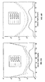
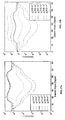
- FIG. 16 shows the angle dependence of the relative detector response (i.e., the data vector) for a source bisecting the two inclusions computed using reference media corresponding to row 3 and column 3 of FIG. 5 . Inspection of these plots clearly reveal a bimodal attenuation profile indicating the presence of two buried objects, a finding consistent with its actual structure. In contrast, this structure is almost completely absent from results derived using the original perturbation formulation (see FIG. 17 ) even though the variation in range of the reference medium is much less than that used in FIG. 16 . This difference is most evident in results given in FIG. 18 that shows the amplitude of the frequency spectrum of the corresponding Fourier transforms.
- a further advantage of the current method compared to the previously described SART-Type algorithm is that we are able to directly evaluate intensity difference values for which no mismatches exist between the computed intensity values, I r , and the Jacobian matrix, Wr. Y.L. Graber, J. Chang and R.L. Barbour "Imaging of multiple targets in dense scattering media", in Proc. Experimental and numerical methods for solving ill-posed inverse problems: Medical and non-medical applications, SPIE, 2570, 219-234, (1995 ) (the disclosures of which are incorporated herein by reference). Not only does this reduce systematic errors, but produces solutions that can be updated by iterative methods. As reported here, error analysis studies have demonstrated that the current methodology produces remarkable stable solutions having excellent qualitative accuracy.
- the described methodology has the effect of desensitizing the solution of boundary value problems to specific features of the boundary.
- One practical consequence of this is that, unlike the standard perturbation formulation, the current formulation is less sensitive to a detailed knowledge of the external boundary of tissue, a quantity not easily measured.
Landscapes
- Physics & Mathematics (AREA)
- Biochemistry (AREA)
- Health & Medical Sciences (AREA)
- Life Sciences & Earth Sciences (AREA)
- Chemical & Material Sciences (AREA)
- Analytical Chemistry (AREA)
- General Health & Medical Sciences (AREA)
- General Physics & Mathematics (AREA)
- Immunology (AREA)
- Pathology (AREA)
- Optics & Photonics (AREA)
- Investigating Or Analysing Materials By Optical Means (AREA)
- Image Processing (AREA)
- Analysing Materials By The Use Of Radiation (AREA)
Claims (12)
- Procédé consistant à imager au moins une propriété (δx) d'au moins un support cible de diffusion, comportant les étapes consistant à :générer un premier vecteur (I) de données mesurées et un deuxième vecteur (I0) de données mesurées, le premier vecteur de données mesurées étant indicatif d'une première énergie émergente qui émerge d'au moins un support cible, le deuxième vecteur de données mesurées étant indicatif d'une seconde énergie émergente qui émerge dudit au moins un support cible, ledit deuxième vecteur étant différent dudit premier vecteur, ladite première énergie émergente et ladite seconde énergie émergente provenant en grande partie d'au moins une source dirigeant de l'énergie dans ledit au moins un support cible, et chaque index dudit premier vecteur et dudit deuxième vecteur est un index de paire source/détecteur qui parcourt chaque paire de source-détecteur,générer un troisième vecteur (Ir) de lectures de détecteur calculé correspondant à un support de référence, ledit troisième vecteur étant des données de référence qui sont indicatives de l'énergie émergente du support de référence, dans lequel un index dudit troisième vecteur est ledit index de paire de source/détecteur,dériver un quatrième vecteur d'au moins lesdits premier et deuxième vecteurs, dans lequel un index dudit quatrième vecteur est ledit index de paire de source/détecteur, dans lequel chaque composant dudit quatrième vecteur est déterminé soit par la différence entre un composant correspondant dudit premier vecteur sur un composant correspondant dudit deuxième vecteur par rapport à ce composant du deuxième vecteur, soit par le logarithme naturel du quotient des composants correspondants dudit premier vecteur et dudit deuxième vecteur,résoudre une équation de perturbation modifiée d'un problème d'inversion de transport par rayonnement pour un changement relatif entre une propriété connue dudit support de référence et une propriété inconnue correspondante dudit au moins un support cible, dans lequel l'équation de perturbation modifiée concerne le quatrième vecteur et ledit troisième vecteur pour le changement relat(δx) de la propriété inconnue correspondante , etgénérer, en utilisant un ordinateur, une image représentative de ladite propriété inconnue correspondante de ladite au moins une cible.
- Procédé selon la revendication 1, dans lequel l'équation de perturbation modifiée a la forme suivante :

and
où i est ledit index de paire de source/détecteur pour chaque paire de source/détecteur, j est un nombre d'éléments qui va de 1 à N, N est le nombre d'éléments de volume, δx est un vecteur des changements relatifs entre une propriété connue du support de référence et la propriété inconnue correspondante dudit au moins un support cible pour des éléments de volume correspondant du support de référence et du support cible, les éléments de volume étant une grille imaginaire de régions contiguës formant une représentation du support cible et du support de référence, Wr est une matrice de pondération décrivant l'influence que chaque élément de la pluralité d'éléments de volume du support de référence a sur l'énergie émergente au niveau d'un point sur le support de référence, Ir est le troisième vecteur, I est le premier vecteur de données mesurées et I0 est le deuxième vecteur de données mesurées. - Procédé selon la revendication 1, dans lequel l'équation de perturbation modifiée a la forme suivante :


où i est ledit index de paire de source/détecteur pour chaque paire de source/détecteur, j et un nombre d'éléments qui va de 1 à N, N est le nombre d'éléments de volume, δx est un vecteur des changements relatifs entre ladite propriété connue du support de référence et ladite propriété inconnue correspondante dudit au moins un support cible pour des éléments de volume correspondant du support de référence et dudit au moins un support cible, les éléments de volume étant une grille imaginaire de régions contiguës non chevauchantes formant une représentation dudit au moins un support cible et du support de référence, Wr est une matrice de pondération décrivant une influence que chaque élément de la pluralité d'éléments de volume du support de référence a sur l'énergie émergente au niveau d'un point sur le support de référence, où Ir est le vecteur de données de référence indicatif de l'énergie émergente du support de référence, I est le premier vecteur de données mesurées et I0 est le deuxième vecteur de données mesurées, Wr' est une matrice dérivée de Wr et IrδI' est un vecteur qui représente un logarithme naturel d'un rapport de chaque composant dudit premier vecteur de données mesurées sur un composant correspondant dudit deuxième vecteur de données mesurées. - Procédé selon la revendication 1, dans lequel ladite propriété inconnue correspondante est au moins l'une d'un coefficient d'absorption et d'un coefficient de diffusion.
- Procédé selon la revendication 1, dans lequel ladite au moins une cible est un support de cible identique.
- Procédé selon la revendication 1, dans lequel le premier vecteur de données mesurées est obtenu à partir d'un premier support cible et le deuxième vecteur de données mesurées est obtenu à partir d'un deuxième support cible qui différent dudit premier support cible.
- Procédé selon la revendication 1, dans lequel le premier vecteur de données mesurées est obtenu à un premier instant et le deuxième vecteur de données mesurées est obtenu à un deuxième instant.
- Procédé selon la revendication 1, dans lequel le premier vecteur de données mesurées est obtenu à un premier instant et le deuxième vecteur de données mesurées est une moyenne établie en fonction du temps d'une pluralité de mesures.
- Procédé selon la revendication 1, comportant en outre de générer une image représentant les changements relatifs en coupe transversale de ladite propriété inconnue correspondante.
- Système pour imager au moins une propriété (δx) d'au moins un support cible de diffusion, comportant :des moyens adaptés pour générer un premier vecteur (I) de données mesurées et un deuxième vecteur (I0) de données mesurées, le premier vecteur de données mesurées étant indicatif d'une première énergie émergente qui émerge d'au moins un support cible, le deuxième vecteur de données mesurées étant indicatif d'une seconde énergie émergente qui émerge dudit au moins un support cible, ledit deuxième vecteur étant différent dudit premier vecteur, ladite première énergie émergente et ladite seconde énergie émergente provenant en grande partie d'au moins une source dirigeant de l'énergie dans ledit au moins un support cible, et chaque index dudit premier vecteur et dudit deuxième vecteur est un index de paire source/détecteur qui parcourt chaque paire de source-détecteur,des moyens adaptés pour générer un troisième vecteur (Ir) de lectures de détecteur calculé correspondant à un support de référence, ledit troisième vecteur étant des données de référence qui sont indicatives de l'énergie émergente du support de référence, dans lequel un index dudit troisième vecteur est ledit index de paire de source/détecteur,des moyens adaptés pour dériver un quatrième vecteur d'au moins lesdits premier et deuxième vecteurs, dans lequel un index dudit quatrième vecteur est ledit index de paire de source/détecteur, dans lequel chaque composant dudit quatrième vecteur est déterminé soit par la différence entre un composant correspondant dudit premier vecteur sur un composant correspondant dudit deuxième vecteur par rapport à ce composant du deuxième vecteur, soit par le logarithme naturel du quotient des composants correspondants dudit premier vecteur et dudit deuxième vecteur,des moyens adaptés pour résoudre une équation de perturbation modifiée d'un problème d'inversion de transport par rayonnement pour un changement relatif entre une propriété connue dudit support de référence et une propriété inconnue correspondante dudit au moins un support cible, dans lequel l'équation de perturbation modifiée concerne le quatrième vecteur et ledit troisième vecteur pour le changement relatif de la propriété inconnue correspondante (δx), etun ordinateur configuré pour générer une image représentative de ladite propriété inconnue correspondante de ladite au moins une cible.
- Système selon la revendication 10, dans lequel l'équation de perturbation modifiée a la forme suivante :

and
où i est ledit index de paire de source/détecteur pour chaque paire de source/détecteur, j est un nombre d'éléments qui va de 1 à N, N est le nombre d'éléments de volume, δx est un vecteur des changements relatifs entre une propriété connue du support de référence et la propriété inconnue correspondante dudit au moins un support cible pour des éléments de volume correspondant du support de référence et du support cible, les éléments de volume étant une grille imaginaire de régions contiguës formant une représentation du support cible et du support de référence, Wr est une matrice de pondération décrivant l'influence que chaque élément de la pluralité d'éléments de volume du support de référence a sur l'énergie émergente au niveau d'un point sur le support de référence, Ir est le troisième vecteur, I est le premier vecteur de données mesurées et I 0 est le deuxième vecteur de données mesurées. - Système selon la revendication 10, dans lequel l'équation de perturbation modifiée a la forme suivante :


où i est ledit index de paire de source/détecteur pour chaque paire de source/détecteur, j et un nombre d'éléments qui va de 1 à N, N est le nombre d'éléments de volume, δx est un vecteur des changements relatifs entre ladite propriété connue du support de référence et ladite propriété inconnue correspondante dudit au moins un support cible pour des éléments de volume correspondant du support de référence et dudit au moins un support cible, les éléments de volume étant une grille imaginaire de régions contiguës non chevauchantes formant une représentation dudit au moins un support cible et du support de référence, Wr est une matrice de pondération décrivant une influence que chaque élément de la pluralité d'éléments de volume du support de référence a sur l'énergie émergente au niveau d'un point sur le support de référence, où Ir est le vecteur de données de référence indicatif de l'énergie émergente du support de référence, I est le premier vecteur de données mesurées et I0 est le deuxième vecteur de données mesurées, Wr' est une matrice dérivée de Wr et Ir, δI' est un vecteur qui représente un logarithme naturel d'un rapport de chaque composant dudit premier vecteur de données mesurées sur un composant correspondant dudit deuxième vecteur de données mesurées.
Applications Claiming Priority (7)
| Application Number | Priority Date | Filing Date | Title |
|---|---|---|---|
| US15376999P | 1999-09-14 | 1999-09-14 | |
| US15392699P | 1999-09-14 | 1999-09-14 | |
| US153769P | 1999-09-14 | ||
| US153926P | 1999-09-14 | ||
| US15409999P | 1999-09-15 | 1999-09-15 | |
| US154099P | 1999-09-15 | ||
| PCT/US2000/025156 WO2001020546A2 (fr) | 1999-09-14 | 2000-09-14 | Imagerie de milieux de diffusion au moyen de valeurs de detection relatives |
Publications (3)
| Publication Number | Publication Date |
|---|---|
| EP1303832A2 EP1303832A2 (fr) | 2003-04-23 |
| EP1303832A4 EP1303832A4 (fr) | 2009-07-01 |
| EP1303832B1 true EP1303832B1 (fr) | 2013-05-15 |
Family
ID=27387489
Family Applications (1)
| Application Number | Title | Priority Date | Filing Date |
|---|---|---|---|
| EP00963433.8A Expired - Lifetime EP1303832B1 (fr) | 1999-09-14 | 2000-09-14 | Imagerie de milieux de diffusion au moyen de valeurs de detection relatives |
Country Status (5)
| Country | Link |
|---|---|
| EP (1) | EP1303832B1 (fr) |
| JP (1) | JP4913299B2 (fr) |
| AU (1) | AU7484800A (fr) |
| CA (1) | CA2384839C (fr) |
| WO (1) | WO2001020546A2 (fr) |
Families Citing this family (25)
| Publication number | Priority date | Publication date | Assignee | Title |
|---|---|---|---|---|
| US6662128B2 (en) | 2002-01-18 | 2003-12-09 | The Research Foundation Of State University Of New York | Normalized-constraint algorithm for minimizing inter-parameter crosstalk in imaging of scattering media |
| CA2481518A1 (fr) | 2002-04-06 | 2003-10-23 | Randall L. Barbour | Systeme et procede de quantification de la reponse dynamique d'un systeme cible |
| CA2481650A1 (fr) | 2002-04-06 | 2003-10-23 | Randall L. Barbour | Modification de la methode de difference normalisee pour une tomographie optique en temps reel |
| JP5196840B2 (ja) * | 2007-04-26 | 2013-05-15 | キヤノン株式会社 | 情報処理装置および方法 |
| JP5595534B2 (ja) * | 2007-05-15 | 2014-09-24 | キヤノン株式会社 | 生体情報イメージング装置、生体情報の解析方法、及び生体情報のイメージング方法 |
| US8392529B2 (en) | 2007-08-27 | 2013-03-05 | Pme Ip Australia Pty Ltd | Fast file server methods and systems |
| US9904969B1 (en) | 2007-11-23 | 2018-02-27 | PME IP Pty Ltd | Multi-user multi-GPU render server apparatus and methods |
| US10311541B2 (en) | 2007-11-23 | 2019-06-04 | PME IP Pty Ltd | Multi-user multi-GPU render server apparatus and methods |
| WO2009067675A1 (fr) | 2007-11-23 | 2009-05-28 | Mercury Computer Systems, Inc. | Système de visualisation client-serveur à traitement de données hybride |
| WO2009067680A1 (fr) | 2007-11-23 | 2009-05-28 | Mercury Computer Systems, Inc. | Procédés et appareil de segmentation automatique d'image |
| WO2011065929A1 (fr) | 2007-11-23 | 2011-06-03 | Mercury Computer Systems, Inc. | Appareil de serveur de rendu multi-utilisateurs et multi-gpu et procédés associés |
| CA2781393C (fr) | 2009-11-19 | 2017-08-08 | Modulated Imaging, Inc. | Procede et appareil pour analyse de milieux troubles par detection mono-element en utilisant une illumination structuree |
| JP2012237595A (ja) | 2011-05-10 | 2012-12-06 | Sumitomo Electric Ind Ltd | 光トモグラフィ装置 |
| US8892192B2 (en) | 2012-11-07 | 2014-11-18 | Modulated Imaging, Inc. | Efficient modulated imaging |
| JP5518167B2 (ja) * | 2012-12-11 | 2014-06-11 | キヤノン株式会社 | 情報処理装置および方法 |
| US11244495B2 (en) | 2013-03-15 | 2022-02-08 | PME IP Pty Ltd | Method and system for rule based display of sets of images using image content derived parameters |
| US11183292B2 (en) | 2013-03-15 | 2021-11-23 | PME IP Pty Ltd | Method and system for rule-based anonymized display and data export |
| US10540803B2 (en) | 2013-03-15 | 2020-01-21 | PME IP Pty Ltd | Method and system for rule-based display of sets of images |
| US10070839B2 (en) | 2013-03-15 | 2018-09-11 | PME IP Pty Ltd | Apparatus and system for rule based visualization of digital breast tomosynthesis and other volumetric images |
| US8976190B1 (en) | 2013-03-15 | 2015-03-10 | Pme Ip Australia Pty Ltd | Method and system for rule based display of sets of images |
| US9509802B1 (en) | 2013-03-15 | 2016-11-29 | PME IP Pty Ltd | Method and system FPOR transferring data to improve responsiveness when sending large data sets |
| US9984478B2 (en) | 2015-07-28 | 2018-05-29 | PME IP Pty Ltd | Apparatus and method for visualizing digital breast tomosynthesis and other volumetric images |
| US11599672B2 (en) | 2015-07-31 | 2023-03-07 | PME IP Pty Ltd | Method and apparatus for anonymized display and data export |
| US10909679B2 (en) | 2017-09-24 | 2021-02-02 | PME IP Pty Ltd | Method and system for rule based display of sets of images using image content derived parameters |
| CN117452485B (zh) * | 2023-12-26 | 2024-03-12 | 中国科学院精密测量科学与技术创新研究院 | 基于声vti散射模式矩阵的共炮域高斯束偏移反演方法 |
Family Cites Families (10)
| Publication number | Priority date | Publication date | Assignee | Title |
|---|---|---|---|---|
| JP3142079B2 (ja) * | 1992-03-19 | 2001-03-07 | 株式会社日立製作所 | 光ct装置 |
| JP3107927B2 (ja) * | 1992-10-06 | 2000-11-13 | 浜松ホトニクス株式会社 | 散乱吸収体の光学情報計測装置及び方法 |
| US5625458A (en) * | 1994-11-10 | 1997-04-29 | Research Foundation Of City College Of New York | Method and system for imaging objects in turbid media using diffusive fermat photons |
| JP3771339B2 (ja) * | 1996-01-18 | 2006-04-26 | 浜松ホトニクス株式会社 | 光ct装置及び光ctによる画像再構成方法 |
| JP3662376B2 (ja) * | 1996-05-10 | 2005-06-22 | 浜松ホトニクス株式会社 | 内部特性分布の計測方法および装置 |
| JP3660761B2 (ja) * | 1996-10-03 | 2005-06-15 | 技術研究組合医療福祉機器研究所 | 散乱体の吸収情報の計測方法及び装置 |
| WO1998024361A2 (fr) * | 1996-12-03 | 1998-06-11 | Koninklijke Philips Electronics N.V. | Procede et appareil de representation de l'interieur d'un milieu trouble |
| JP2001510361A (ja) * | 1996-12-03 | 2001-07-31 | コーニンクレッカ フィリップス エレクトロニクス エヌ ヴィ | 混濁媒体の内部を画像化する方法及び装置 |
| US5963658A (en) * | 1997-01-27 | 1999-10-05 | University Of North Carolina | Method and apparatus for detecting an abnormality within a host medium |
| EP0963174B1 (fr) * | 1997-11-22 | 2004-03-17 | Koninklijke Philips Electronics N.V. | Procede de localisation d'un objet dans un milieu trouble |
-
2000
- 2000-09-14 WO PCT/US2000/025156 patent/WO2001020546A2/fr active Application Filing
- 2000-09-14 EP EP00963433.8A patent/EP1303832B1/fr not_active Expired - Lifetime
- 2000-09-14 CA CA2384839A patent/CA2384839C/fr not_active Expired - Fee Related
- 2000-09-14 JP JP2001524053A patent/JP4913299B2/ja not_active Expired - Fee Related
- 2000-09-14 AU AU74848/00A patent/AU7484800A/en not_active Abandoned
Also Published As
| Publication number | Publication date |
|---|---|
| WO2001020546A3 (fr) | 2003-02-06 |
| CA2384839C (fr) | 2013-12-24 |
| JP4913299B2 (ja) | 2012-04-11 |
| WO2001020546A9 (fr) | 2002-10-03 |
| EP1303832A4 (fr) | 2009-07-01 |
| JP2003528291A (ja) | 2003-09-24 |
| AU7484800A (en) | 2001-04-17 |
| EP1303832A2 (fr) | 2003-04-23 |
| CA2384839A1 (fr) | 2001-03-22 |
| WO2001020546A2 (fr) | 2001-03-22 |
Similar Documents
| Publication | Publication Date | Title |
|---|---|---|
| EP1303832B1 (fr) | Imagerie de milieux de diffusion au moyen de valeurs de detection relatives | |
| US7616984B2 (en) | Modification of the normalized difference method for real-time optical tomography | |
| Yalavarthy et al. | Weight‐matrix structured regularization provides optimal generalized least‐squares estimate in diffuse optical tomography | |
| Barbour | A perturbation approach for optical diffusion tomography using continuous-wave and time-resolved data | |
| US6662128B2 (en) | Normalized-constraint algorithm for minimizing inter-parameter crosstalk in imaging of scattering media | |
| US7046832B1 (en) | Imaging of scattering media using relative detector values | |
| AU2003209271A1 (en) | Normalized-constraint algorithm for minimizing inter-parameter crosstalk in imaging of scattering media | |
| US7142304B1 (en) | Method and system for enhanced imaging of a scattering medium | |
| US7617080B2 (en) | Image enhancement by spatial linear deconvolution | |
| Song et al. | Statistical analysis of nonlinearly reconstructed near-infrared tomographic images. II. Experimental interpretation | |
| JP2001264245A (ja) | 散乱吸収体内部の光路分布計算方法 | |
| Willemink et al. | Imaging of acoustic attenuation and speed of sound maps using photoacoustic measurements | |
| US7099519B2 (en) | Method and system for enhancing solutions to a system of linear equations | |
| Siddalingaiah et al. | Randomized recursive techniques for image reconstruction in diffuse optical tomography | |
| Hillman et al. | Differential imaging in heterogeneous media: limitations of linearization assumptions in optical tomography | |
| Campbell et al. | Limitations of decomposition-based imaging of longitudinal absorber configurations | |
| EP1221033B1 (fr) | Procede et systeme d'imagerie amelioree d'un milieu de diffusion | |
| Arridge et al. | Reconstruction in optical tomography using MRI based prior knowledge | |
| Chang et al. | Image reconstruction of targets in random media from continuous wave laser measurements and simulated data | |
| Pei et al. | Normalized-constraint method for minimizing interparameter cross-talk in reconstructed images of spatially heterogeneous scattering and absorption coefficients | |
| Pei et al. | A fast reconstruction algorithm for implementation of time-series DC optical tomography | |
| Hawrysz et al. | Measurement and model error assessment of a single-pixel frequency-domain photon migration apparatus and diffusion model for imaging applications | |
| Yaling Pei et al. | scattering and absorption coefficients | |
| Boverman et al. | Adjoint field methods for non-linear tomographic medical imaging problems | |
| Boverman et al. | Three dimensional nonlinear inversion for diffuse optical tomography |
Legal Events
| Date | Code | Title | Description |
|---|---|---|---|
| PUAI | Public reference made under article 153(3) epc to a published international application that has entered the european phase |
Free format text: ORIGINAL CODE: 0009012 |
|
| 17P | Request for examination filed |
Effective date: 20020410 |
|
| AK | Designated contracting states |
Designated state(s): AT BE CH CY DE DK ES FI FR GB GR IE IT LI LU MC NL PT SE |
|
| AX | Request for extension of the european patent |
Extension state: AL LT LV MK RO SI |
|
| A4 | Supplementary search report drawn up and despatched |
Effective date: 20090529 |
|
| 17Q | First examination report despatched |
Effective date: 20090803 |
|
| REG | Reference to a national code |
Ref country code: DE Ref legal event code: R079 Ref document number: 60048011 Country of ref document: DE Free format text: PREVIOUS MAIN CLASS: G06K0009000000 Ipc: G01N0021470000 |
|
| GRAP | Despatch of communication of intention to grant a patent |
Free format text: ORIGINAL CODE: EPIDOSNIGR1 |
|
| RIC1 | Information provided on ipc code assigned before grant |
Ipc: G01N 21/49 20060101ALI20120416BHEP Ipc: G01N 21/47 20060101AFI20120416BHEP |
|
| GRAS | Grant fee paid |
Free format text: ORIGINAL CODE: EPIDOSNIGR3 |
|
| GRAA | (expected) grant |
Free format text: ORIGINAL CODE: 0009210 |
|
| AK | Designated contracting states |
Kind code of ref document: B1 Designated state(s): AT BE CH CY DE DK ES FI FR GB GR IE IT LI LU MC NL PT SE |
|
| AX | Request for extension of the european patent |
Extension state: AL LT LV MK RO SI |
|
| REG | Reference to a national code |
Ref country code: CH Ref legal event code: EP Ref country code: GB Ref legal event code: FG4D |
|
| REG | Reference to a national code |
Ref country code: AT Ref legal event code: REF Ref document number: 612391 Country of ref document: AT Kind code of ref document: T Effective date: 20130615 |
|
| REG | Reference to a national code |
Ref country code: IE Ref legal event code: FG4D |
|
| REG | Reference to a national code |
Ref country code: DE Ref legal event code: R096 Ref document number: 60048011 Country of ref document: DE Effective date: 20130711 |
|
| REG | Reference to a national code |
Ref country code: AT Ref legal event code: MK05 Ref document number: 612391 Country of ref document: AT Kind code of ref document: T Effective date: 20130515 |
|
| REG | Reference to a national code |
Ref country code: LT Ref legal event code: MG9D |
|
| REG | Reference to a national code |
Ref country code: NL Ref legal event code: VDEP Effective date: 20130515 |
|
| PG25 | Lapsed in a contracting state [announced via postgrant information from national office to epo] |
Ref country code: PT Free format text: LAPSE BECAUSE OF FAILURE TO SUBMIT A TRANSLATION OF THE DESCRIPTION OR TO PAY THE FEE WITHIN THE PRESCRIBED TIME-LIMIT Effective date: 20130916 Ref country code: ES Free format text: LAPSE BECAUSE OF FAILURE TO SUBMIT A TRANSLATION OF THE DESCRIPTION OR TO PAY THE FEE WITHIN THE PRESCRIBED TIME-LIMIT Effective date: 20130826 Ref country code: AT Free format text: LAPSE BECAUSE OF FAILURE TO SUBMIT A TRANSLATION OF THE DESCRIPTION OR TO PAY THE FEE WITHIN THE PRESCRIBED TIME-LIMIT Effective date: 20130515 Ref country code: FI Free format text: LAPSE BECAUSE OF FAILURE TO SUBMIT A TRANSLATION OF THE DESCRIPTION OR TO PAY THE FEE WITHIN THE PRESCRIBED TIME-LIMIT Effective date: 20130515 Ref country code: SE Free format text: LAPSE BECAUSE OF FAILURE TO SUBMIT A TRANSLATION OF THE DESCRIPTION OR TO PAY THE FEE WITHIN THE PRESCRIBED TIME-LIMIT Effective date: 20130515 Ref country code: GR Free format text: LAPSE BECAUSE OF FAILURE TO SUBMIT A TRANSLATION OF THE DESCRIPTION OR TO PAY THE FEE WITHIN THE PRESCRIBED TIME-LIMIT Effective date: 20130816 |
|
| PG25 | Lapsed in a contracting state [announced via postgrant information from national office to epo] |
Ref country code: DK Free format text: LAPSE BECAUSE OF FAILURE TO SUBMIT A TRANSLATION OF THE DESCRIPTION OR TO PAY THE FEE WITHIN THE PRESCRIBED TIME-LIMIT Effective date: 20130515 Ref country code: BE Free format text: LAPSE BECAUSE OF FAILURE TO SUBMIT A TRANSLATION OF THE DESCRIPTION OR TO PAY THE FEE WITHIN THE PRESCRIBED TIME-LIMIT Effective date: 20130515 |
|
| PGFP | Annual fee paid to national office [announced via postgrant information from national office to epo] |
Ref country code: DE Payment date: 20131029 Year of fee payment: 14 Ref country code: FR Payment date: 20131017 Year of fee payment: 14 Ref country code: GB Payment date: 20131028 Year of fee payment: 14 |
|
| PG25 | Lapsed in a contracting state [announced via postgrant information from national office to epo] |
Ref country code: NL Free format text: LAPSE BECAUSE OF FAILURE TO SUBMIT A TRANSLATION OF THE DESCRIPTION OR TO PAY THE FEE WITHIN THE PRESCRIBED TIME-LIMIT Effective date: 20130515 Ref country code: IT Free format text: LAPSE BECAUSE OF FAILURE TO SUBMIT A TRANSLATION OF THE DESCRIPTION OR TO PAY THE FEE WITHIN THE PRESCRIBED TIME-LIMIT Effective date: 20130515 |
|
| PLBE | No opposition filed within time limit |
Free format text: ORIGINAL CODE: 0009261 |
|
| STAA | Information on the status of an ep patent application or granted ep patent |
Free format text: STATUS: NO OPPOSITION FILED WITHIN TIME LIMIT |
|
| 26N | No opposition filed |
Effective date: 20140218 |
|
| PG25 | Lapsed in a contracting state [announced via postgrant information from national office to epo] |
Ref country code: MC Free format text: LAPSE BECAUSE OF FAILURE TO SUBMIT A TRANSLATION OF THE DESCRIPTION OR TO PAY THE FEE WITHIN THE PRESCRIBED TIME-LIMIT Effective date: 20130515 |
|
| REG | Reference to a national code |
Ref country code: CH Ref legal event code: PL |
|
| REG | Reference to a national code |
Ref country code: DE Ref legal event code: R097 Ref document number: 60048011 Country of ref document: DE Effective date: 20140218 |
|
| REG | Reference to a national code |
Ref country code: IE Ref legal event code: MM4A |
|
| PG25 | Lapsed in a contracting state [announced via postgrant information from national office to epo] |
Ref country code: IE Free format text: LAPSE BECAUSE OF NON-PAYMENT OF DUE FEES Effective date: 20130914 Ref country code: CH Free format text: LAPSE BECAUSE OF NON-PAYMENT OF DUE FEES Effective date: 20130930 Ref country code: LI Free format text: LAPSE BECAUSE OF NON-PAYMENT OF DUE FEES Effective date: 20130930 |
|
| REG | Reference to a national code |
Ref country code: DE Ref legal event code: R119 Ref document number: 60048011 Country of ref document: DE |
|
| GBPC | Gb: european patent ceased through non-payment of renewal fee |
Effective date: 20140914 |
|
| REG | Reference to a national code |
Ref country code: DE Ref legal event code: R119 Ref document number: 60048011 Country of ref document: DE Effective date: 20150401 |
|
| REG | Reference to a national code |
Ref country code: FR Ref legal event code: ST Effective date: 20150529 |
|
| PG25 | Lapsed in a contracting state [announced via postgrant information from national office to epo] |
Ref country code: CY Free format text: LAPSE BECAUSE OF FAILURE TO SUBMIT A TRANSLATION OF THE DESCRIPTION OR TO PAY THE FEE WITHIN THE PRESCRIBED TIME-LIMIT Effective date: 20130515 |
|
| PG25 | Lapsed in a contracting state [announced via postgrant information from national office to epo] |
Ref country code: LU Free format text: LAPSE BECAUSE OF NON-PAYMENT OF DUE FEES Effective date: 20130914 Ref country code: DE Free format text: LAPSE BECAUSE OF NON-PAYMENT OF DUE FEES Effective date: 20150401 Ref country code: GB Free format text: LAPSE BECAUSE OF NON-PAYMENT OF DUE FEES Effective date: 20140914 |
|
| PG25 | Lapsed in a contracting state [announced via postgrant information from national office to epo] |
Ref country code: FR Free format text: LAPSE BECAUSE OF NON-PAYMENT OF DUE FEES Effective date: 20140930 |