EP1303033B1 - Eingangsspannungsregelung für eine Steuerschaltung durch Aktuatorleistungsmodulation - Google Patents
Eingangsspannungsregelung für eine Steuerschaltung durch Aktuatorleistungsmodulation Download PDFInfo
- Publication number
- EP1303033B1 EP1303033B1 EP02020108A EP02020108A EP1303033B1 EP 1303033 B1 EP1303033 B1 EP 1303033B1 EP 02020108 A EP02020108 A EP 02020108A EP 02020108 A EP02020108 A EP 02020108A EP 1303033 B1 EP1303033 B1 EP 1303033B1
- Authority
- EP
- European Patent Office
- Prior art keywords
- voltage
- controller
- predefined
- actuator
- control
- Prior art date
- Legal status (The legal status is an assumption and is not a legal conclusion. Google has not performed a legal analysis and makes no representation as to the accuracy of the status listed.)
- Expired - Lifetime
Links
Images

Classifications
-
- H—ELECTRICITY
- H02—GENERATION; CONVERSION OR DISTRIBUTION OF ELECTRIC POWER
- H02J—ELECTRIC POWER NETWORKS; CIRCUIT ARRANGEMENTS OR SYSTEMS FOR SUPPLYING OR DISTRIBUTING ELECTRIC POWER; SYSTEMS FOR STORING ELECTRIC ENERGY
- H02J1/00—Circuit arrangements for DC mains or DC distribution networks
-
- H—ELECTRICITY
- H02—GENERATION; CONVERSION OR DISTRIBUTION OF ELECTRIC POWER
- H02M—APPARATUS FOR CONVERSION BETWEEN AC AND AC, BETWEEN AC AND DC, OR BETWEEN DC AND DC, AND FOR USE WITH MAINS OR SIMILAR POWER SUPPLY SYSTEMS; CONVERSION OF DC OR AC INPUT POWER INTO SURGE OUTPUT POWER; CONTROL OR REGULATION THEREOF
- H02M7/00—Conversion of AC power input into DC power output; Conversion of DC power input into AC power output
- H02M7/42—Conversion of DC power input into AC power output without possibility of reversal
- H02M7/44—Conversion of DC power input into AC power output without possibility of reversal by static converters
- H02M7/48—Conversion of DC power input into AC power output without possibility of reversal by static converters using discharge tubes with control electrode or semiconductor devices with control electrode
- H02M7/53—Conversion of DC power input into AC power output without possibility of reversal by static converters using discharge tubes with control electrode or semiconductor devices with control electrode using devices of a triode or transistor type requiring continuous application of a control signal
- H02M7/537—Conversion of DC power input into AC power output without possibility of reversal by static converters using discharge tubes with control electrode or semiconductor devices with control electrode using devices of a triode or transistor type requiring continuous application of a control signal using semiconductor devices only, e.g. single switched pulse inverters
- H02M7/5387—Conversion of DC power input into AC power output without possibility of reversal by static converters using discharge tubes with control electrode or semiconductor devices with control electrode using devices of a triode or transistor type requiring continuous application of a control signal using semiconductor devices only, e.g. single switched pulse inverters in a bridge configuration
- H02M7/53871—Conversion of DC power input into AC power output without possibility of reversal by static converters using discharge tubes with control electrode or semiconductor devices with control electrode using devices of a triode or transistor type requiring continuous application of a control signal using semiconductor devices only, e.g. single switched pulse inverters in a bridge configuration with automatic control of output voltage or current
-
- B—PERFORMING OPERATIONS; TRANSPORTING
- B60—VEHICLES IN GENERAL
- B60R—VEHICLES, VEHICLE FITTINGS, OR VEHICLE PARTS, NOT OTHERWISE PROVIDED FOR
- B60R16/00—Electric or fluid circuits specially adapted for vehicles and not otherwise provided for; Arrangement of elements of electric or fluid circuits specially adapted for vehicles and not otherwise provided for
- B60R16/02—Electric or fluid circuits specially adapted for vehicles and not otherwise provided for; Arrangement of elements of electric or fluid circuits specially adapted for vehicles and not otherwise provided for electric constitutive elements
- B60R16/03—Electric or fluid circuits specially adapted for vehicles and not otherwise provided for; Arrangement of elements of electric or fluid circuits specially adapted for vehicles and not otherwise provided for electric constitutive elements for supply of electrical power to vehicle subsystems or for
-
- H—ELECTRICITY
- H02—GENERATION; CONVERSION OR DISTRIBUTION OF ELECTRIC POWER
- H02J—ELECTRIC POWER NETWORKS; CIRCUIT ARRANGEMENTS OR SYSTEMS FOR SUPPLYING OR DISTRIBUTING ELECTRIC POWER; SYSTEMS FOR STORING ELECTRIC ENERGY
- H02J2105/00—Networks for supplying or distributing electric power characterised by their spatial reach or by the load
- H02J2105/30—Networks for supplying or distributing electric power characterised by their spatial reach or by the load the load networks being external to vehicles, i.e. exchanging power with vehicles
- H02J2105/33—Networks for supplying or distributing electric power characterised by their spatial reach or by the load the load networks being external to vehicles, i.e. exchanging power with vehicles exchanging power with road vehicles
-
- H—ELECTRICITY
- H02—GENERATION; CONVERSION OR DISTRIBUTION OF ELECTRIC POWER
- H02M—APPARATUS FOR CONVERSION BETWEEN AC AND AC, BETWEEN AC AND DC, OR BETWEEN DC AND DC, AND FOR USE WITH MAINS OR SIMILAR POWER SUPPLY SYSTEMS; CONVERSION OF DC OR AC INPUT POWER INTO SURGE OUTPUT POWER; CONTROL OR REGULATION THEREOF
- H02M1/00—Details of apparatus for conversion
- H02M1/0003—Details of control, feedback or regulation circuits
- H02M1/0016—Control circuits providing compensation of output voltage deviations using feedforward of disturbance parameters
- H02M1/0022—Control circuits providing compensation of output voltage deviations using feedforward of disturbance parameters the disturbance parameters being input voltage fluctuations
Definitions
- Mechanical linkage and hydraulic pressure operated controls for vehicles are well known in the art, and generally comprise control input devices operated by a user such as steering wheels, shift levers, and foot pedals which are directly interlinked with various vehicle controls individually or by combinations of mechanical push rods, gears, cables, or pressurized hydraulic systems.
- Such controls have been utilized in vehicles such as automobiles and trucks since the inception and initial manufacturer of such vehicles.
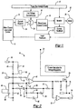
- Fig. 2 represents an analog circuit that represents one possible embodiment of a low Voltage Control Circuit 16 for regulating the voltage of the electrical signal in loop 13 above a predefined minimum.
- the predefined minimum voltage is some voltage greater than the minimum operation voltage requirement for controller 14.
- controller 14 can be prevented from entering a reset mode as a result of a voltage dip occurring during a high current demand request by motor 20.
- the bus voltage to be regulated comes into circuit 16 as the SWBAT input 30.
- the +5V signal 32 provides a control reference for circuit 16.
- the VREG* signal is an output from circuit 16 as a signal to indicate to system 10 that the power bus 12 voltage has dipped and the voltage regulation function of circuit 16 is modifying the original current request.
- VREG* 34 is a logic "1"
- the voltage control circuitry is off and the system 10 is in normal operation.
- VREG* is a logic "0”
- the voltage control circuitry is active and the system is in a reduced output capability condition.
- circuit 16 represents but one embodiment of an analog circuit to perform a voltage limiting function, and those skilled in the art will recognize that other variations of circuit 16 will perform a like function.
- the monitoring of reduction percentage is illustrated at 208. If the reduction percentage is less than or equal to the maximum, the load current reduction is performed to the calculated level at 210 and transmitted to summer 124. If, on the other hand, the calculated load current reduction is greater than the maximum, the load current reduction is set to the maximum permitted at 212 and transmitted to summer 124.
- the maximum load current reduction must be defined as a system condition to maintain proper system operation.
Landscapes
- Engineering & Computer Science (AREA)
- Power Engineering (AREA)
- Electric Propulsion And Braking For Vehicles (AREA)
- Direct Current Feeding And Distribution (AREA)
- Dc-Dc Converters (AREA)
Claims (8)
- Fahrzeugsystem (10), das eine Spannungsregelungsbetätigung enthält, wobei das System folgendes umfaßt:eine Stromversorgung (12), die elektrischen Strom mit einer ersten vordefinierten Höchstspannung liefert;einen Controller (18) zum Steuern einer elektrischen Last in dem System, wobei der Controller eine erste vordefinierte Mindestarbeitsspannung aufweist;einen Spannungsregler (16) in Kommunikation mit dem Controller (18) und der Stromversorgung (12), wobei der Regler eine Steuersystemeingangsspannung in dem System (10) erfaßt, und als Reaktion auf einen Spannungseinbruch über einen vorbestimmten Wert reduziert der Regler ein Stromanforderungssignal von der Last, um die Systemspannung bei einer zweiten vordefinierten Mindestspannung zu halten, die größer ist als die erste vordefinierte Mindestarbeitsspannung; undwobei die Last mindestens ein Aktuator (20) ist, der Steuereingänge von der Spannungsregelungsbetätigung empfängt, um eine Fahrzeugsystemfunktion auszuführen, und die Steuereingaben von der Spannungsregelungsbetätigung spannungsgeregelt werden.
- System nach Anspruch 1, wobei der Spannungsregler (16) eine Analogschaltung in elektrischer Kommunikation mit dem Controller (18) und dem Aktuator (20) ist.
- System nach Anspruch 2, wobei die Analogschaltung folgendes enthält:einen Verstärker (42), der auf eine abnehmende Spannung in dem System derart reagiert, daß der Verstärker aktiv wird, wenn sich die Spannung der zweiten vordefinierten Mindestsystemspannung annähert, wobei der Verstärker aktiv wird und eine erhöhte Spannungsausgabe liefert; undeinen Transistor (70), der auf die Verstärkerspannungsausgabe so reagiert, daß der Transistor in einen leitenden Zustand eintritt, wenn von dem Transistor eine Aktivierungsschwellenspannung erfaßt wird, wobei der leitende Zustand des Transistors dann Strom von dem System leitet, um eine Stromanforderung für den Aktuator (20) zu reduzieren und dadurch eine Systemspannung auf der zweiten Mindestspannung zu halten.
- System nach Anspruch 3, wobei die Schaltung weiterhin eine Überbrückung (36) zum Auswählen zwischen abwechselnden vorbestimmten Spannungsminima enthält.
- System nach Anspruch 4, wobei die Schaltung weiterhin einen Logikausgang (34) zu dem Controller enthält, wobei der Logikausgang einen ersten Zustand, der einen aktiven Zustand der Analogschaltung an den Controller kommuniziert, und einen zweiten Zustand, der einen inaktiven Zustand der Analogschaltung kommuniziert, aufweist.
- System nach Anspruch 1, wobei:der Controller (18) ein Mikroprozessor ist; undder Spannungsregler (16) eine Softwarefunktion innerhalb des Mikroprozessors umfaßt.
- System nach Anspruch 6, wobei die Softwarefunktion die folgenden Schritte umfaßt:Abtasten der Stromversorgungsspannung (12);Berechnen einer Stromlastreduzierung, wenn die abgetastete Spannung unter einer vordefinierten Grenze liegt;Bestimmen, ob die berechnete Reduzierung größer ist als ein vordefiniertes MaximumReduzieren der Stromlast durch die berechnete Reduzierung, wenn die berechnete Reduzierung unter dem vordefinierten Maximum liegt; undReduzieren der Stromlast um das vordefinierte Maximum, wenn die berechnete Reduzierung gleich dem oder größer als das vordefinierte Maximum ist.
- Verfahren zum Regeln der Spannung eines Fahrzeugsystems von dem Typ mit einer Stromversorgung (12), einem Controller (18) und einem Aktuator (20), wobei das Verfahren die folgenden Schritte umfaßt:Definieren einer Mindestsystemspannung;Erfassen einer Systemeingangsspannung für das System während des Betriebs des Aktuators (20);Reduzieren eines Stromanforderungssignals von dem Aktuator (20), wenn sich die erfaßte Systemeingangsspannung einem vorbestimmten Minimum annähert; undBegrenzen der Systemspannung auf ein vordefiniertes Minimum.
Applications Claiming Priority (2)
| Application Number | Priority Date | Filing Date | Title |
|---|---|---|---|
| US974693 | 2001-10-09 | ||
| US09/974,693 US6624531B2 (en) | 2001-10-09 | 2001-10-09 | Controller input voltage regulation by actuator power modulation |
Publications (3)
| Publication Number | Publication Date |
|---|---|
| EP1303033A2 EP1303033A2 (de) | 2003-04-16 |
| EP1303033A3 EP1303033A3 (de) | 2004-01-21 |
| EP1303033B1 true EP1303033B1 (de) | 2006-03-29 |
Family
ID=25522343
Family Applications (1)
| Application Number | Title | Priority Date | Filing Date |
|---|---|---|---|
| EP02020108A Expired - Lifetime EP1303033B1 (de) | 2001-10-09 | 2002-09-07 | Eingangsspannungsregelung für eine Steuerschaltung durch Aktuatorleistungsmodulation |
Country Status (4)
| Country | Link |
|---|---|
| US (1) | US6624531B2 (de) |
| EP (1) | EP1303033B1 (de) |
| DE (1) | DE60210181T2 (de) |
| ES (1) | ES2261569T3 (de) |
Families Citing this family (15)
| Publication number | Priority date | Publication date | Assignee | Title |
|---|---|---|---|---|
| US6704629B2 (en) * | 2001-11-30 | 2004-03-09 | Bppower, Inc. | Device for monitoring motor vehicle's electric power and method therefor |
| US7924937B2 (en) * | 2002-03-04 | 2011-04-12 | Stmicroelectronics N.V. | Resonant power converter for radio frequency transmission and method |
| KR100686421B1 (ko) * | 2002-03-04 | 2007-02-23 | 에스티마이크로일렉트로닉스 엔.브이. | 공진전원변환 및 방법을 위한 코더장치 |
| US6917502B2 (en) | 2002-03-28 | 2005-07-12 | Delphi Technologies, Inc. | Power supply circuit and method for a motor vehicle electrical accessory load |
| JP2005027363A (ja) * | 2003-06-30 | 2005-01-27 | Aisin Seiki Co Ltd | 車載システム制御装置 |
| US7212006B2 (en) | 2004-07-02 | 2007-05-01 | Bppower, Inc. | Method and apparatus for monitoring the condition of a battery by measuring its internal resistance |
| US7525266B2 (en) * | 2006-01-30 | 2009-04-28 | Honeywell International Inc. | Inverter loop latch with integrated AC detection reset |
| US20070194791A1 (en) | 2006-02-17 | 2007-08-23 | Bppower Inc. | Method and apparatus for monitoring the condition of a battery by measuring its internal resistance |
| US7928735B2 (en) | 2007-07-23 | 2011-04-19 | Yung-Sheng Huang | Battery performance monitor |
| US8049372B2 (en) * | 2008-07-01 | 2011-11-01 | GM Global Technology Operations LLC | Precharging a high-voltage bus using a voltage-regulated power supply |
| US8040092B2 (en) * | 2008-11-24 | 2011-10-18 | GM Global Technology Operations LLC | Power supply topology for a multi-processor controller in an electric traction system |
| US8606444B2 (en) * | 2010-12-29 | 2013-12-10 | Caterpillar Inc. | Machine and power system with electrical energy storage device |
| JP5691950B2 (ja) * | 2011-09-05 | 2015-04-01 | 株式会社デンソー | 電圧監視装置 |
| DE102012220803B4 (de) * | 2012-11-14 | 2021-06-10 | Bayerische Motoren Werke Aktiengesellschaft | Vorrichtung zur Spannungsversorgung einer Systemkomponente und Systemkomponente |
| US20170131362A1 (en) * | 2015-11-09 | 2017-05-11 | Digi International Inc. | Method for determining remaining battery life of at least one electrochemical cell or battery across a large temperature range |
Family Cites Families (6)
| Publication number | Priority date | Publication date | Assignee | Title |
|---|---|---|---|---|
| JPS5854830A (ja) * | 1981-09-29 | 1983-03-31 | 日産自動車株式会社 | 車両用電子回路の電源監視装置 |
| US5200674A (en) * | 1990-11-16 | 1993-04-06 | Aichi Sharyo Co., Ltd. | Electric power supply device for mobile vehicular apparatus with aerial cabin having force-feedback manipulator |
| JP3398935B2 (ja) * | 1997-10-07 | 2003-04-21 | 矢崎総業株式会社 | 車両用電源供給装置 |
| JPH11334497A (ja) * | 1998-05-22 | 1999-12-07 | Yazaki Corp | バッテリー上がり防止装置及び方法 |
| US6147597A (en) * | 1999-03-31 | 2000-11-14 | Facory; Omar | Vehicle-integrated access control device |
| JP2000326805A (ja) * | 1999-05-20 | 2000-11-28 | Calsonic Kansei Corp | 車両等の電源装置 |
-
2001
- 2001-10-09 US US09/974,693 patent/US6624531B2/en not_active Expired - Lifetime
-
2002
- 2002-09-07 ES ES02020108T patent/ES2261569T3/es not_active Expired - Lifetime
- 2002-09-07 DE DE60210181T patent/DE60210181T2/de not_active Expired - Lifetime
- 2002-09-07 EP EP02020108A patent/EP1303033B1/de not_active Expired - Lifetime
Also Published As
| Publication number | Publication date |
|---|---|
| EP1303033A3 (de) | 2004-01-21 |
| US6624531B2 (en) | 2003-09-23 |
| DE60210181D1 (de) | 2006-05-18 |
| DE60210181T2 (de) | 2007-04-05 |
| EP1303033A2 (de) | 2003-04-16 |
| ES2261569T3 (es) | 2006-11-16 |
| US20030067221A1 (en) | 2003-04-10 |
Similar Documents
| Publication | Publication Date | Title |
|---|---|---|
| US6624531B2 (en) | Controller input voltage regulation by actuator power modulation | |
| US6762945B2 (en) | Method and system for producing a supply voltage during a first and second operating mode | |
| CN109937164B (zh) | 用于监测具有自动化行驶功能的机动车的方法和用于执行该方法的设备 | |
| EP1032517B1 (de) | Elektromechanisches bremssystem | |
| US5608271A (en) | Electric current distribution system for automotive vehicles | |
| EP3025400B1 (de) | Drehmomentsicherheitsmonitor für den motor eines elektrofahrzeugs | |
| US20180345947A1 (en) | Method for Operating a Parking Brake and Control Device for Operating a Parking Brake | |
| US20180345938A1 (en) | Method for Operating a Parking Brake and Control Unit for Operating a Parking Brake | |
| CN101312869A (zh) | 电源控制器 | |
| JP2004518583A (ja) | 車両のブレーキ装置のための電子制御システム | |
| CN101516736A (zh) | 由车载电池供电的车载控制设备 | |
| CN102046428A (zh) | 用于供电网络的开关模块和包括至少一个开关模块的供电网络 | |
| JP4598245B2 (ja) | 電気制御式ブレーキ装置 | |
| JP2000043749A (ja) | 操舵制御装置および操舵装置 | |
| KR101010016B1 (ko) | 병렬 연결된 전력공급장치들 간의 부하 분담 제어에의펄스폭 변조의 이용 | |
| EP3667885B1 (de) | Stromversorgungssteuerungssystem und verfahren | |
| EP0075931B2 (de) | Sicherheitssystem in einer Energieregelschaltung für eine elektronische Fahrzeugschaltung | |
| CN109001585B (zh) | 用于诊断电池连接状态的系统和方法 | |
| EP3647138B1 (de) | Fahrzeugbremssystem | |
| CN118871338A (zh) | 用于运行车辆的转向系统的方法 | |
| CN113906302A (zh) | 用于测定电的供应导线的电阻的方法 | |
| JP2001524799A (ja) | 直流アクチュエータのためのパルス幅変調操作信号を発生する方法と回路装置 | |
| CN113631459A (zh) | 用于运行用来操控电气转向装置的转向控制装置的方法和转向控制装置 | |
| JPH08239034A (ja) | 機関車用スロットル制御装置及び同装置におけるアナログ信号の帰還方法 | |
| DE19751429A1 (de) | Schaltungsanordnung zur Spannungsüberwachung einer geregelten Ausgangsspannung in einem Kraftfahrzeug |
Legal Events
| Date | Code | Title | Description |
|---|---|---|---|
| PUAI | Public reference made under article 153(3) epc to a published international application that has entered the european phase |
Free format text: ORIGINAL CODE: 0009012 |
|
| AK | Designated contracting states |
Designated state(s): AT BE BG CH CY CZ DE DK EE ES FI FR GB GR IE IT LI LU MC NL PT SE SK TR |
|
| AX | Request for extension of the european patent |
Extension state: AL LT LV MK RO SI |
|
| PUAL | Search report despatched |
Free format text: ORIGINAL CODE: 0009013 |
|
| AK | Designated contracting states |
Kind code of ref document: A3 Designated state(s): AT BE BG CH CY CZ DE DK EE ES FI FR GB GR IE IT LI LU MC NL PT SE SK TR |
|
| AX | Request for extension of the european patent |
Extension state: AL LT LV MK RO SI |
|
| RIC1 | Information provided on ipc code assigned before grant |
Ipc: 7H 02M 7/48 B Ipc: 7H 02J 1/00 B Ipc: 7B 60R 16/02 A Ipc: 7H 02J 7/00 B |
|
| 17P | Request for examination filed |
Effective date: 20040203 |
|
| 17Q | First examination report despatched |
Effective date: 20040618 |
|
| AKX | Designation fees paid |
Designated state(s): DE ES FR GB IT SE |
|
| GRAP | Despatch of communication of intention to grant a patent |
Free format text: ORIGINAL CODE: EPIDOSNIGR1 |
|
| GRAS | Grant fee paid |
Free format text: ORIGINAL CODE: EPIDOSNIGR3 |
|
| GRAA | (expected) grant |
Free format text: ORIGINAL CODE: 0009210 |
|
| AK | Designated contracting states |
Kind code of ref document: B1 Designated state(s): DE ES FR GB IT SE |
|
| REG | Reference to a national code |
Ref country code: GB Ref legal event code: FG4D |
|
| REF | Corresponds to: |
Ref document number: 60210181 Country of ref document: DE Date of ref document: 20060518 Kind code of ref document: P |
|
| REG | Reference to a national code |
Ref country code: SE Ref legal event code: TRGR |
|
| ET | Fr: translation filed | ||
| REG | Reference to a national code |
Ref country code: ES Ref legal event code: FG2A Ref document number: 2261569 Country of ref document: ES Kind code of ref document: T3 |
|
| PLBE | No opposition filed within time limit |
Free format text: ORIGINAL CODE: 0009261 |
|
| STAA | Information on the status of an ep patent application or granted ep patent |
Free format text: STATUS: NO OPPOSITION FILED WITHIN TIME LIMIT |
|
| 26N | No opposition filed |
Effective date: 20070102 |
|
| REG | Reference to a national code |
Ref country code: FR Ref legal event code: PLFP Year of fee payment: 15 |
|
| REG | Reference to a national code |
Ref country code: FR Ref legal event code: PLFP Year of fee payment: 16 |
|
| REG | Reference to a national code |
Ref country code: FR Ref legal event code: PLFP Year of fee payment: 17 |
|
| PGFP | Annual fee paid to national office [announced via postgrant information from national office to epo] |
Ref country code: FR Payment date: 20210927 Year of fee payment: 20 Ref country code: IT Payment date: 20210930 Year of fee payment: 20 |
|
| PGFP | Annual fee paid to national office [announced via postgrant information from national office to epo] |
Ref country code: SE Payment date: 20210921 Year of fee payment: 20 Ref country code: DE Payment date: 20210904 Year of fee payment: 20 Ref country code: GB Payment date: 20210923 Year of fee payment: 20 |
|
| PGFP | Annual fee paid to national office [announced via postgrant information from national office to epo] |
Ref country code: ES Payment date: 20211019 Year of fee payment: 20 |
|
| REG | Reference to a national code |
Ref country code: DE Ref legal event code: R071 Ref document number: 60210181 Country of ref document: DE |
|
| REG | Reference to a national code |
Ref country code: ES Ref legal event code: FD2A Effective date: 20220926 |
|
| REG | Reference to a national code |
Ref country code: GB Ref legal event code: PE20 Expiry date: 20220906 |
|
| PG25 | Lapsed in a contracting state [announced via postgrant information from national office to epo] |
Ref country code: GB Free format text: LAPSE BECAUSE OF EXPIRATION OF PROTECTION Effective date: 20220906 Ref country code: ES Free format text: LAPSE BECAUSE OF EXPIRATION OF PROTECTION Effective date: 20220908 |