EP1302790A1 - Optical fiber wire holder, fused connection device, cutting device, and method of connecting optical fiber - Google Patents
Optical fiber wire holder, fused connection device, cutting device, and method of connecting optical fiber Download PDFInfo
- Publication number
- EP1302790A1 EP1302790A1 EP01947930A EP01947930A EP1302790A1 EP 1302790 A1 EP1302790 A1 EP 1302790A1 EP 01947930 A EP01947930 A EP 01947930A EP 01947930 A EP01947930 A EP 01947930A EP 1302790 A1 EP1302790 A1 EP 1302790A1
- Authority
- EP
- European Patent Office
- Prior art keywords
- optical fiber
- holder
- groove
- clamping
- fusion
- Prior art date
- Legal status (The legal status is an assumption and is not a legal conclusion. Google has not performed a legal analysis and makes no representation as to the accuracy of the status listed.)
- Granted
Links
Images




Classifications
-
- G—PHYSICS
- G02—OPTICS
- G02B—OPTICAL ELEMENTS, SYSTEMS OR APPARATUS
- G02B6/00—Light guides; Structural details of arrangements comprising light guides and other optical elements, e.g. couplings
- G02B6/24—Coupling light guides
- G02B6/36—Mechanical coupling means
-
- G—PHYSICS
- G02—OPTICS
- G02B—OPTICAL ELEMENTS, SYSTEMS OR APPARATUS
- G02B6/00—Light guides; Structural details of arrangements comprising light guides and other optical elements, e.g. couplings
- G02B6/24—Coupling light guides
- G02B6/255—Splicing of light guides, e.g. by fusion or bonding
- G02B6/2555—Alignment or adjustment devices for aligning prior to splicing
-
- G—PHYSICS
- G02—OPTICS
- G02B—OPTICAL ELEMENTS, SYSTEMS OR APPARATUS
- G02B6/00—Light guides; Structural details of arrangements comprising light guides and other optical elements, e.g. couplings
- G02B6/24—Coupling light guides
- G02B6/245—Removing protective coverings of light guides before coupling
-
- G—PHYSICS
- G02—OPTICS
- G02B—OPTICAL ELEMENTS, SYSTEMS OR APPARATUS
- G02B6/00—Light guides; Structural details of arrangements comprising light guides and other optical elements, e.g. couplings
- G02B6/24—Coupling light guides
- G02B6/25—Preparing the ends of light guides for coupling, e.g. cutting
-
- G—PHYSICS
- G02—OPTICS
- G02B—OPTICAL ELEMENTS, SYSTEMS OR APPARATUS
- G02B6/00—Light guides; Structural details of arrangements comprising light guides and other optical elements, e.g. couplings
- G02B6/24—Coupling light guides
- G02B6/255—Splicing of light guides, e.g. by fusion or bonding
- G02B6/2551—Splicing of light guides, e.g. by fusion or bonding using thermal methods, e.g. fusion welding by arc discharge, laser beam, plasma torch
-
- G—PHYSICS
- G02—OPTICS
- G02B—OPTICAL ELEMENTS, SYSTEMS OR APPARATUS
- G02B6/00—Light guides; Structural details of arrangements comprising light guides and other optical elements, e.g. couplings
- G02B6/24—Coupling light guides
- G02B6/36—Mechanical coupling means
- G02B6/3628—Mechanical coupling means for mounting fibres to supporting carriers
- G02B6/3632—Mechanical coupling means for mounting fibres to supporting carriers characterised by the cross-sectional shape of the mechanical coupling means
- G02B6/3636—Mechanical coupling means for mounting fibres to supporting carriers characterised by the cross-sectional shape of the mechanical coupling means the mechanical coupling means being grooves
-
- G—PHYSICS
- G02—OPTICS
- G02B—OPTICAL ELEMENTS, SYSTEMS OR APPARATUS
- G02B6/00—Light guides; Structural details of arrangements comprising light guides and other optical elements, e.g. couplings
- G02B6/24—Coupling light guides
- G02B6/36—Mechanical coupling means
- G02B6/3616—Holders, macro size fixtures for mechanically holding or positioning fibres, e.g. on an optical bench
-
- G—PHYSICS
- G02—OPTICS
- G02B—OPTICAL ELEMENTS, SYSTEMS OR APPARATUS
- G02B6/00—Light guides; Structural details of arrangements comprising light guides and other optical elements, e.g. couplings
- G02B6/24—Coupling light guides
- G02B6/36—Mechanical coupling means
- G02B6/3628—Mechanical coupling means for mounting fibres to supporting carriers
- G02B6/3648—Supporting carriers of a microbench type, i.e. with micromachined additional mechanical structures
- G02B6/3652—Supporting carriers of a microbench type, i.e. with micromachined additional mechanical structures the additional structures being prepositioning mounting areas, allowing only movement in one dimension, e.g. grooves, trenches or vias in the microbench surface, i.e. self aligning supporting carriers
Definitions
- the present invention relates to a fusion-splicing method for splicing optical fibers, a cleaving apparatus for cleaving the tip of optical fibers, a fusion-splicing apparatus for splicing optical fibers which have been cleaved at the tip thereof, and an optical fiber holder.
- a fusion-splicing method As a method for splicing optical fibers, a fusion-splicing method has been practiced.
- This fusion-splicing method consists of the following three steps.
- the first step involves stripping the coating from the tip of the optical fiber using a stripping apparatus called stripper (remover).
- the second step comprises cleaving the optical fiber thus exposed to a predetermined length using an optical fiber cleaving apparatus.
- the third step comprises fusion-splicing the optical fibers with the tip thereof abutted to each other using a fusion-splicing apparatus.
- the fusion-splicing step electric discharge starts while the tip of the optical fibers are kept at a predetermined distance and positioned at the fusion starting position. Subsequently, one or both of the optical fibers are pushed in a direction such that the distance between the tip thereof is reduced. Thereafter, the tip of the optical fibers are spliced at the fusion end position to complete fusion-splice.
- the first method comprises positioning the coated portion of the optical fiber in the vicinity of the tip thereof with the optical fiber exposed at the tip thereof using a V-groove.
- the second method comprises positioning the exposed optical fiber itself using a V-groove. In any of these methods, positioning of the tip of the optical fiber must be conducted precisely.
- Fig. 9 is a diagram illustrating a structure for supporting an optical fiber in a conventional fusion-splicing apparatus. In Fig. 9, only a mechanism for supporting one of the two optical fibers is shown.
- the reference numeral 1 indicates a coated optical fiber
- the reference numeral 1a indicates an optical fiber
- the reference numeral 31 indicates an optical fiber holding table
- the reference numerals 32a, 32b each indicate a clamping member
- the reference numeral 33 indicates a slider mechanism
- the reference numeral 34 indicates a supporting table.
- the optical fiber holding table 31 is provided with a groove (not shown) in which the coated optical fiber 1 having a protective coating is received.
- the coated optical fiber 1 received in the groove is clamped by the clamping members 32a, 32b.
- the optical fiber holding table 31 is supported on the supporting table 34 via the slider mechanism 33 in such an arrangement that it can move along the axis of the coated optical fiber 1 thus clamped.
- the supporting table 34 and the other supporting table (not shown) are disposed opposed to each other and are supported on the respective optical fiber holding table 31. These supporting tables are arranged such that they can be moved by the respective movement mechanism (not shown) to align the tip of the optical fiber 1a obtained by exposing the optical fiber 1.
- an optical fiber is set in a stripper.
- the optical fiber is then stripped at the tip thereof.
- the optical fiber is set in a cleaving apparatus.
- the optical fiber is then cleaved at the tip thereof.
- the optical fiber is set in the optical fiber holding table 31 of the fusion-splicing apparatus described in connection with Fig. 9 where it is then subjected to fusion-splice.
- the length (cleaved length) of the optical fiber thus cleaved is not constant itself.
- this fusion-splicing apparatus employs a procedure requiring the removal of the optical fiber from the cleaving apparatus and the transfer of the optical fiber to the optical fiber holding table 31, the position in the longitudinal direction of the coated optical fiber 1 clamped by the clamping members 32a, 32b is not constant. As a result, it takes much time to align the tip of the optical fiber. Further, since the coated optical fiber 1 is clamped at the tip thereof by the clamping member 32a, the coating may be curved if it is not sufficiently clamped. As a result, the position of the tip of the optical fiber 1a cannot be stably fixed with a good precision.
- Fig. 10 illustrates an embodiment of the holder mechanism for fusion-splicing apparatus designed to improve the precision of fixing of an optical fiber.
- Like numerals are used for like parts in Figs. 9 and 10. The description of parts similar to those of Fig. 9 will be omitted.
- the reference numerals 34a, 34b each indicate a supporting table
- the reference numeral 35 indicates a V-groove member
- the reference numeral 36 indicates a clamping member.
- the V-groove member 35 and the clamping member 36 are provided besides the optical fiber holding table 31 for holding the optical fiber 1 and the clamping member 32a.
- the coated optical fiber 1 is clamped by the V-groove member 35 and the clamping member 36 at the position close to the tip thereof.
- the clamping force applied to the coated optical fiber 1 at the position close to the tip thereof can be enhanced, making it possible to improve the precision of fixing of the optical fiber 1a.
- the V-groove member 35 is supported on the supporting table 34b. Another supporting table (not shown) is disposed opposed to the supporting table 34b.
- the coated optical fiber 1 clamped in the respective V-groove member 35 is stripped at the tip thereof.
- the fusion-splicing apparatus comprising the foregoing holder mechanism
- the optical fiber holding table 31 moves forward.
- the coated optical fiber 1 makes sliding movement forward against the clamping force by the V-groove member 35 and the clamping member 36. Accordingly, when the clamping force is large, the coated optical fiber 1 can undergo buckling or cannot move through the V-groove, making it impossible to perform good splice. On the contrary, when the clamping force is small, the coated optical fiber 1 cannot be stably clamped.
- Fig. 11 is a schematic diagram illustrating a holder mechanism described in Japanese Patent Unexamined Publication No. Hei. 9-113572.
- Fig. 11(A) is a schematic diagram.
- Fig. 11(B) is a sectional view of the fitting portion.
- Like numerals are used for like parts in Figs. 9, 10 and 11. The description of parts similar to those of Fig. 9 will be omitted.
- the reference numeral 37 indicates a holder
- the reference numeral 37a indicates a tapered pin
- the reference numeral 38 indicates a holder mount
- the reference numeral 38a indicates a tapered hole.
- the optical fiber 1 which has been stripped at the tip thereof is clamped in the holder 37.
- the holder 37 is prepared for each of the optical fiber 1 to be spliced.
- the holder 37 comprises the tapered pin 37a provided at the bottom thereof.
- a tapered hole At the holder mounting portion of the cleaving apparatus for cleaving the optical fiber 1a of the coated optical fiber 1 is provided.
- the holder 37 is positioned in the cleaving apparatus using the tapered pin 37a and the tapered hole. Accordingly, the cleaved position of the optical fiber is constant with respect to the holder 37.
- the holder having the coated optical fiber 1 clamped therein is removed from the cleaving apparatus, and then mounted on the holder mount 38 of the fusion-splicing apparatus as shown in Fig. 11(A).
- the holder mount 38 has a tapered 38a formed at the position corresponding to the position of the tapered hole in the holder mount of the cleaving apparatus as shown in Fig. 11(B).
- the length of the optical fiber thus cleaved is constant itself.
- the holder can be positioned and mounted on the holder mount 38, making it possible to mount the optical fiber 1a in such an arrangement that the tip thereof is always at a constant position.
- the coated optical fiber 1 is set at the position close to the tip thereof in the V-groove member 35, which has the same structure as described in connection with Fig. 10, there arises the same problems as described in connection with Fig. 10.
- coated optical fibers 1 having an outer diameter of 0.25 mm, 0.4 mm, 0.9 mm, etc. are commercially available, the holder mechanism of Fig. 11 is disadvantageous in that the V-groove member 35 must be exchanged and adjusted according to the outer diameter of the coated optical fiber 1.
- the variation of the height of the central axis of the coated optical fiber 1 depending on the outer diameter of the coated optical fiber must be dealt with. In other words, every time a coated optical fiber 1 having an outer diameter different from that of the previous coated optical fiber is spliced, the height of the microscope or the position of the discharge electrodes must be adjusted.
- the coated portion of the coated optical fiber is clamped by a V-groove member. Similar problems occur with the case where the optical fiber stripped its coating is clamped by the V-groove member. In other words, since optical fibers 1a having an outer diameter of 80 ⁇ m, 125 ⁇ m, 150 ⁇ m, 280 ⁇ m, etc. are commercially available, the V-groove member must be exchanged or adjusted according to the outer diameter of the optical fiber in order to monitor the spliced portion without adjusting the height of the microscope even when optical fibers 1a having different outer diameters are clamped by the V-groove member.
- An object of the present invention is to provide an optical fiber holder, a fusion-splicing apparatus, a cleaving apparatus and a method for splicing optical fibers which can deal with coated optical fibers or optical fibers having different outer diameters and accurately positioning the tip of optical fiber during fusion-splice.
- the present invention lies in an optical fiber holder which is used for a stripping apparatus, cleaving apparatus and fusion-splicing apparatus in common, comprising a holder main body having a groove for inserting a coated optical fiber therein and a clamping member for clamping the coated optical fiber inserted in the groove, and a V-groove portion provided ahead of the holder main body for inserting the coated optical fiber therein, wherein the V-groove portion is clamped by a clamping member which is mounted on a holder mount in the stripping apparatus, cleaving apparatus or fusion-splicing apparatus and which is compressed toward the V-groove portion by a spring member.
- the present invention also lies in the foregoing optical fiber holder, wherein the optical fiber holder is prepared for each of a plurality of kinds of optical fibers having different outer diameters and the groove and the V-groove in the V-groove portion of each of the optical fiber holders are formed in such an arrangement that the central axis of the coated optical fiber clamped at these grooves are in the same position independent of the outer diameter of optical fiber.
- the present invention further lies in a method for splicing optical fibers which comprises effecting a sequence of steps involving coating stripping, cleaning, cleaving and fusion-splice without removing the optical fiber from the optical fiber holder to splice optical fibers.
- the present invention still further lies in a fusion-splicing apparatus having an optical fiber holder comprising a holder main body having a groove for inserting a coated optical fiber therein and a clamping member for clamping the coated optical fiber inserted in the groove and a V-groove portion provided ahead of the holder main body for inserting a coated optical fiber therein, and a holder mount for mounting the optical fiber holder thereon, characterized in that the holder mount comprises a positioning portion for positioning the optical fiber holder and a supporting portion for supporting the clamping member which is compressed toward the V-groove portion by a spring member.
- the present invention still further lies in a cleaving apparatus having an optical fiber holder comprising a holder main body having a groove for inserting a coated optical fiber therein and a clamping member for clamping the coated optical fiber inserted in the groove and a V-groove portion provided ahead of the holder main body for inserting the coated optical fiber therein, a holder mount for mounting the optical fiber holder thereon, a cleaving blade, a V-groove member for inserting a coated optical fiber therein, and a clamping member for clamping the coated optical fiber inserted in the V-groove member, characterized in that the holder mount has a positioning portion for positioning the optical fiber holder and a supporting portion for supporting the clamping member which is compressed toward the V-groove portion by a spring member and the cleaving blade is positioned interposed between the V-groove portion and the V-groove member and is adapted to make a cleave on the optical fiber clamped between the V-groove
- the present invention still further lies in an optical fiber holder which is used for a cleaving apparatus and fusion-splicing apparatus in common, comprising a holder main body having a groove for inserting a coated optical fiber therein and a clamping member for clamping the coated optical fiber inserted in the groove, and a V-groove portion provided ahead of the holder main body for inserting the coated optical fiber therein, wherein the V-groove portion is clamped by a clamping member which is mounted on a holder mount in the cleaving apparatus or fusion-splicing apparatus and which is compressed toward the V-groove portion by a spring member.
- the present invention still further lies in the foregoing optical fiber holder, wherein the optical fiber holder is prepared for each of a plurality of kinds of optical fibers having different outer diameters and/or coated optical fibers having different outer diameters, the groove in the optical fiber holders are formed in such an arrangement that the central axis of the coated optical fibers clamped at these grooves are in the same position independent of the outer diameter of coated optical fiber and the V-groove in the V-groove portions are formed in such an arrangement that the central axis of coated optical fibers clamped at these grooves are in the same position independent of the outer diameter of coated optical fiber.
- the present invention still further lies in a method for splicing optical fibers which comprises effecting a sequence of steps involving cleaving and fusion-splice without removing the optical fiber from the optical fiber holder in order to splice optical fibers.
- the present invention still further lies in a fusion-splicing apparatus having an optical fiber holder comprising a holder main body having a groove for inserting a coated optical fiber therein and a clamping member for clamping the coated optical fiber inserted in the groove and a V-groove portion provided ahead of the holder main body for inserting a coated optical fiber therein, and a holder mount for mounting the optical fiber holder thereon, characterized in that the holder mount comprises a positioning portion for positioning the optical fiber holder and a supporting portion for supporting the clamping member which is compressed toward the V-groove portion by a spring member.
- the present invention still further lies in a cleaving apparatus having an optical fiber holder comprising a holder main body having a groove for inserting a coated optical fiber therein and a clamping member for clamping the coated optical fiber inserted in the groove and a V-groove portion provided ahead of the holder main body for inserting the coated optical fiber therein, a holder mount for mounting the optical fiber holder thereon, a cleaving blade, a V-groove member for inserting a coated optical fiber therein, and a clamping member for clamping the coated optical fiber inserted in the V-groove member, characterized in that the holder mount has a positioning portion for positioning the optical fiber holder and a supporting portion for supporting the clamping member which is compressed toward the V-groove portion by a spring member and the cleaving blade is positioned interposed between the V-groove portion and the V-groove member and is adapted to make a cleave on the optical fiber clamped between the V-groove
- Fig . 1 is a schematic diagram illustrating a mechanism for retaining an optical fiber in an embodiment of the fusion-splicing apparatus according to the present invention.
- Fig. 2 is a schematic diagram illustrating an embodiment of the stripping apparatus used in a stripping step.
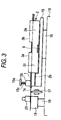
- Fig. 3 is a schematic diagram illustrating an embodiment of the cleaving apparatus used in a cleaving step.
- Fig. 4 is a perspective view illustrating the schematic structure of the holder of Fig. 1.
- Fig. 5 is a perspective view illustrating the schematic structure of a fusion-splicing apparatus comprising the holder of Fig. 4.
- Fig. 6 is a schematic diagram illustrating a mechanism for retaining an optical fiber in another embodiment of the fusion-splicing apparatus according to the present invention.
- Fig. 7 is a perspective view illustrating the schematic structure of an embodiment of the holder of Fig. 6.
- Fig. 8 is a perspective view illustrating the schematic structure of a holder comprising a stopper portion.
- Fig. 9 is a diagram illustrating a structure for supporting an optical fiber in a conventional fusion-splicing apparatus.
- Fig. 10 is a diagram illustrating a holder mechanism in a conventional fusion-splicing apparatus.
- Fig. 11 is a schematic diagram illustrating a conventional holder mechanism.
- the reference numeral 1 indicates a coated optical fiber
- the reference numeral 1a indicates an optical fiber
- the reference numeral 2 indicates a holder
- the reference numeral 2a indicates a holder main body
- the reference numeral 2b indicates a V-groove portion
- the reference numeral 2c indicates a positioning portion
- the reference numeral 2e indicates a V-groove
- the reference numeral 2f indicates a sliding groove
- the reference numeral 2g indicates a magnet
- the reference numerals 3, 3a and 3b each indicate a clamping member
- the reference numeral 3c indicates an elastic material
- the reference numeral 4 indicates a holder mount
- the reference numeral 4a indicates a positioning portion
- the reference numeral 4b indicates a supporting portion
- the reference numeral 4c indicates a raised line
- the reference numeral 4d indicates an arm member
- the reference numeral 5 indicates a slider mechanism
- the reference numeral 6 indicates a supporting table
- the reference numeral 7 indicates a clamping member
- Fig. 1(A) is a schematic diagram illustrating a mechanism for retaining an optical fiber in an embodiment of the fusion-splicing apparatus according to the present invention.
- the reference numeral 1 indicates a coated optical fiber
- the reference numeral 1a indicates an optical fiber
- the reference numeral 2 indicates a holder
- the reference numeral 2a indicates a holder main body
- the reference numeral 2b indicates a V-groove portion
- the reference numeral 2c indicates a positioning portion
- the reference numerals 3a, 3b each indicate a clamping member
- the reference numeral 4 indicates a holder mount
- the reference numeral 4a indicates a positioning portion
- the reference numeral 4b indicates a supporting portion
- the reference numeral 5 indicates a slider mechanism
- the reference numeral 6 indicates a supporting table
- the reference numeral 7 indicates a clamping member
- the reference numeral 8 indicates a spring member
- the reference numeral 9 indicates a magnet.
- Fig. 1 indicates a coated optical fiber
- the holder 2 can clamp the coated optical fiber 1 to be spliced.
- the holder main body 2a has a V-groove portion 2b provided at the forward end thereof which can receive the coated optical fiber 1.
- the coated optical fiber 1 is clamped by the clamping member 7.
- the holder main body 2a has a groove formed also at the rear part following the V-groove portion 2b in which the coated optical fiber 1 can be inserted.
- the coated optical fiber 1 is clamped by the clamping members 3a, 3b.
- the groove in the holder main body 2a may be formed extending from the V-groove of the V-groove portion 2b.
- the form of the groove in the holder main body 2a is not limited to V-groove.
- the groove in the holder main body 2a may have a proper sectional shape such as rectangle.
- the clamping member 7 is supported in such an arrangement that it is compressed toward the V-groove portion 2b by the spring member 8 against the supporting portion 4b.
- the supporting portion 4b is attached to the holder mount 4 via an arm member (not shown) extending from the holder mount 4 and thus is integrated to the holder mount 4.
- the holder 2 in which the coated optical fiber 1 is clamped is attached to and positioned on the holder mount 4.
- the positioning mechanism there may be used a positioning structure described in connection with Fig. 11.
- the corner of the holder main body 2a acts as the positioning portion 2c.
- the position portion 4a formed as a step on the holder mount 4 performs positioning in the forward and backward direction (axial direction of optical fiber 1).
- the holder main body 2a also has an engagement portion (not shown) and a portion to be engaged so that it can be positioned also in the crosswise direction (direction perpendicular to the axis of optical fiber 1).
- the engagement portion and the portion to be engaged there may be used proper engagement structures restricting the crosswise relative movement as well as allowing the forward and backward movement, e.g., raised line extending longitudinally and groove in which the raised line is fitted.
- a clearance is shown provided between the holder 2 and the holder mount 4. However, this clearance is shown for the sake of convenience of display.
- the forward and lower portion of the holder main body 2a is brought in close contact with the holder mount 4.
- the lower portion of the V-groove 2b is brought into close contact with and supported by the holder mount 4.
- the V-groove portion 2b does not need to be supported by the holder mount 4, and there may be a clearance between the V-groove portion 2b and the holder mount 4.
- the lower portion of the V-groove portion 2b is preferably brought into close contact with and supported by the holder mount 4.
- a magnet 9 may be embedded in or otherwise attached to a part, e.g., bottom, of the holder so that the holder 2 can be attracted to the holder mount 4 by magnetic force.
- the holder mount 4 may be formed by a magnetic material.
- a magnet-attracting material maybe attached to the holdermount 4 at the position thereof corresponding to the magnetic 9.
- the holder mount 4 is supported on the supporting table 6 by the slider mechanism 5 in such an arrangement that it can move along the axis of the coated optical fiber 1 thus clamped.
- the supporting table 6 and another supporting table (not shown) disposed opposed to the supporting table 6 are arranged such that they can be moved by the respective moving mechanism (not shown) to align the tip of the optical fiber 1a exposed by stripping the coating from the tip of the coated optical fiber 1 clamped by the respective V-groove portion 2b.
- the holder 2 is prepared according to the dimension, etc. of the coated optical fiber 1 to be spliced.
- the holder described in Fig. 1 (A) is used also in a cleaving apparatus. As shown in Fig. 3, this holder allows accurate positioning of the tip of optical fiber. Also in a stripping apparatus for stripping the coating from the tip of a coated optical fiber, the use of the foregoing holder makes it possible to strip the coating at a position which is reproducible and accurate.
- the stripping apparatus and cleaving apparatus will be described hereinafter with reference to step of processing the terminal of optical fiber for the purpose of fusion-splice using the foregoing common holder.
- Fig. 2 is a schematic diagram illustrating an embodiment of the stripping apparatus used in a stripping step. Like numerals are used for like parts in Figs. 1 and 2. The description of parts similar to those of Fig. 1 will be omitted.
- the reference numeral 10 indicates a holder mount
- the reference numeral 10a indicates a supporting table
- the reference numeral 10b indicates a clamping member
- the reference numeral 10c indicates a spring member
- the reference numeral 11 indicates a movement mechanism
- the reference numeral 12 indicates a stripping portion
- the reference numeral 12a indicates a stripping blade
- the reference numeral 12b indicates an arm portion
- the reference numeral 13 indicates a mount
- the reference numeral 14 indicates a base table.
- the holder mount 10 is arranged such that the holder 2 is mounted by the same mounting structure as the holder mount 4 shown in Fig. 1(A).
- the holder mount 10 is supported on the base table 14 via the movement mechanism 11.
- the movement mechanism 11 has a driving source (not shown) such as motor so that the holder mount 10 can be moved longitudinally along the axis of the optical fiber 1.
- the stripping portion 12 has a stripping blade 12a on the arm portion 12b which can be opened and closed.
- the stripping portion 12 is mounted on the base table 14 via the mount 13.
- Fig. 2(A) illustrates how the holder 2 in which an coated optical fiber 1 is set is mounted on the holder mount 10 of the stripping apparatus.
- the setting of the coated optical fiber 1 in the holder 2 is accomplished with the holder main body 2a and the clamping members 3a, 3b.
- the setting of the coated optical fiber 1 in the stripping apparatus is accomplished with the V-groove portion 2b and the clamping member 10b.
- the clamping member 10b is supported on a supporting member (not shown) which is in turn mounted on the holder mount 10.
- the clamping member 10b is compressed toward the V-groove by the spring member 10C.
- the coated optical fiber 1 set in the holder 2 is not removed from the holder 2 until fusion-splice is completed.
- the position of the coated optical fiber 1 in the holder mount 10 corresponds to the position at which the coated optical fiber 1 in the holder 2 is disposed. This position is the reference position of the coated optical fiber 1.
- the positioning mechanism for positioning the holder 2 in the holder mount 10 is similar to that shown in Fig. 1(A).
- Fig. 2(B) illustrates how the holder mount 10 on which the holder 2 is mounted is moved on the base table 14 by the movement mechanism 11 to the predetermined position at which the striping is effected.
- the arm portion 12b of the stripping portion 12 is closed.
- the stripping blade 12a cuts into the coating of the coated optical fiber 1 to make a notch on the coating of the coated optical fiber 1.
- a part of the coating of the coated optical fiber 1 is caught by the stripping blade 12a.
- a start switch (not shown) is turned ON to start heating by a heat source for heating the coating material.
- heating to a predetermined temperature is maintained.
- the coating is stripped from the tip of the optical fiber 1a beginning with the notch.
- an electrode holder portion (not shown) rises up. Electrical discharge is made at the position where the optical fiber 1a of the coated optical fiber 1 is sandwiched with a gap by the electrodes.
- electrical discharge is made between the electrodes while the holder mount 10 is being moved backward, the remaining of the coating left on the surface of the optical fiber 1a from which the coating has been stripped is burnt away to complete the step of stripping.
- the cleaning is not limited to electrical discharge. A proper cleaning method may be employed such as ultrasonic cleaning in acetone.
- the present embodiment has been described with reference to the arrangement that the holder mount 10 is moved, relative movement is made between the stripping portion 12 and the holder 2.
- the arrangement may be possible such that only the stripping portion 12 moves or both the stripping portion 12 and the holder 2 move.
- the clamping member 10b may not be necessarily provided in the stripping apparatus.
- Fig. 3 is a schematic diagram illustrating an embodiment of the cleaving apparatus used in a cleaving step. Like numerals are used for like parts in Figs. 3 and 1(A). The description of parts similar to those of Fig. 1(A) will be omitted.
- the reference numeral 15 indicates a holder mount
- the reference numeral 15a indicates a supporting portion
- the reference numeral 15b indicates a clamping member
- the reference numeral 15c indicates a spring member
- the reference numeral 16 indicates a fixing table
- the reference numeral 17 indicates a cleaving blade
- the reference numeral 18 indicates a V-groove member
- the reference numeral 19 indicates a fixing table
- the reference numeral 20 indicates a clamping member.
- the holder mount 15 is arranged such that the holder 2 is mounted by the same mounting structure as the holder mount 4 shown in Fig. 1(A).
- the holder mount 15 is supported on the base table 14 via the fixing table 16.
- the cleaving blade 17 is provided in such an arrangement that it can move forward and backward in the direction perpendicular to the optical fiber.
- the position at which cleaving is made is constant in the longitudinal direction of optical fiber.
- the optical fiber 1a of the coated optical fiber 1 is cleaved at the tip thereof at an accurately predetermined position with respect to the reference position at which clamping is made by the holder 2.
- the holder 2 is mounted on the holder mount 15 of the cleaving apparatus in such a manner that the optical fiber is kept being clamped by the holder after the coating is stripped from the optical fiber.
- the positioning mechanism for positioning the holder 2 in the holder mount 15 is the same as the positioning mechanism shown in Fig. 1(A).
- the cleaving blade 17 moves in the direction perpendicular to the optical fiber 1a thus positioned to make a notch on the optical fiber 1a. It has been heretofore practiced to clamp the optical fiber on the both sides thereof between two V-groove members and a clamping member provided in the cleaving apparatus when a notch is made on the optical fiber by the cleaving blade.
- the cleaving apparatus comprises a V-groove member 18 and a clamping member 20 provided closer to the terminal of the optical fiber 1a than the cleaving blade.
- the clamp provided on the side of the cleaving blade opposite the V-groove member 18 and the clamping member 20 is arranged such that the coated portion of the coated optical fiber is clamped by the V-groove portion 2b and the clamping member 15 provided in the holder 2.
- the clamping member 15b is mounted on the holder mount 15 via a supporting member which is not shown. The clamping member 15b is compressed toward the V-groove by the spring member 15c.
- the cleaving of the optical fiber with the cleaving blade is also accomplished by a process which comprises making a cleave on the optical fiber with a cleaving blade while the optical fiber is being clamped and longitudinally tensed.
- the present invention is not limited to the process involving breaking by a bending piece.
- the holder keeps the optical fiber 1 set at the pre-determined position.
- the optical fiber 1 is clamped and cleaved at the holder mount of cleaving apparatus provided in the same dimensional relationship as the holder mount of stripping apparatus.
- the positional relationship between the tip of the coating of the coated optical fiber 1 and the cleaving position of optical fiber 1a is always constant.
- the holder 2 having the optical fiber 1 clamped and retained at the predetermined cleaving position is mounted on the holder mount 4 disposed on the both sides of the fusion-splicing apparatus shown in Fig. 1(A).
- the holder keeps the optical fiber 1 set at the pre-determined position.
- This holder is mounted on the holder mount 4 in the fusion-splicing apparatus in the same dimensional relationship as in the holder mount in the stripping apparatus or cleaving apparatus. In this manner, the tip of the optical fiber 1a in the fusion-splicing apparatus is always at the predetermined fusion-splicing position.
- the holder 2 will be described hereinafter.
- coated optical fibers having various outer diameters, including 0.25 mm, 0.4 mm, 0.9 mm.
- the holder 2 is prepared for each of optical fibers having various outer diameters .
- the depth of the groove for receiving the coated optical fiber 1 therein is varied according to the outer diameter of the coated optical fiber to make the height of the central axis of the coated optical fiber 1 clamped by the holder 2 constant.
- Fig. 1(B) is an enlarged sectional view of an essential part of the V-groove portion 2b in which the coated optical fibers 1 having different diameters are clamped.
- the substrate constituting the V-groove is shown having the same thickness.
- Fig. 1(B) (a) shows the positional relationship between the V-groove and the coated optical fiber 1 in a holder for a coated optical fiber 1 having an outer diameter of 0.25 mm.
- Fig. 1(B) (b) shows the positional relationship between the V-groove and the coated optical fiber 1 in a holder for a coated optical fiber 1 having an outer diameter of 0.4 mm.
- Fig. 1(B) shows the positional relationship between the V-groove and the coated optical fiber 1 in a holder for a coated optical fiber 1 having an outer diameter of 0.4 mm.
- FIG. 1(B) (c) shows the positional relationship between the V-groove and the coated optical fiber 1 in a holder for a coated optical fiber 1 having an outer diameter of 0.9 mm. Even if the outer diameter of the coated optical fiber 1 varies, the central position of the coated optical fiber 1 does not vary so far as the coated optical fiber 1 is positioned in the respective holder. This applies to the groove in the holder main body 2a. The position of the central axis of the coated optical fiber 1 thus clamped relative to the holder remains constant regardless of the outer diameter of the coated optical fiber 1. In this arrangement, even if optical fibers having different outer diameters are to be fusion-spliced, it can be dealt with by properly selecting the holder, eliminating the necessity of changing the position of the constituent parts of the fusion-splicing apparatus to advantage.
- Fig. 4 is a perspective view illustrating the schematic structure of an embodiment of the holder of Fig. 1.
- Fig. 4(A) illustrates how the clamping member is closed.
- Fig. 4(B) illustrates how the clamping member is opened.
- Fig. 4(C) illustrates how the optical fiber is clamped.
- Like numerals are used for like parts in Figs. 1 and 4. The description of parts similar to those of Fig. 1 will be omitted.
- the reference numeral 2e indicates a V-groove
- the reference numeral 2f indicates a sliding groove
- the reference numeral 2g indicates a magnet
- the reference numeral 3 indicates a clamping member
- the reference numeral 3c indicates an elastic material.
- the V-groove 2b is formed integrally with the holder main body 2a as shown in Figs. 4 (A) and 4(B). Further, the V-groove 2e is continuously formed from the forward end of the V-groove portion 2b to the rear end of the holder main body 2a.
- the clamping member 3 is rotatably mounted on the holder main body 2a.
- An elastic material which undergoes elastic deformation to press the coated optical fiber 1, such as natural rubber and synthetic rubber, is embedded in the clamping member 3 at the portion corresponding to the V-groove 2e.
- the holder 2 has the sliding groove 2f formed on the bottom of the holder 2 over the length of the holder 2.
- the sliding groove 2f is fitted on a raised line formed having a dimension and shape adapted for the sliding groove 2f of the holder mount (not shown).
- the holder 2 is positioned perpendicular to the axial direction of the coated optical fiber thus clamped so that it can slide along the holder mount.
- the clamping member 3 is closed and attracted by the magnet 2g to clamp the coated optical fiber 1.
- the coated optical fiber 1 is not moved but is kept at the foregoing pre-determined position.
- the holder of the present embodiment is adapted to clamp an optical fiber which is in the form of single-core optical fiber.
- the holder can be used for an apparatus for fusion-splicing optical fiber ribbon containing planarity of optical fibers.
- the holder adapted for optical fiber ribbon is arranged such that the groove is formed according to the width of the optical fiber ribbon.
- Fig. 5(A) is a perspective view illustrating the schematic structure of an embodiment of the fusion-splicing apparatus comprising the holder described in Fig. 4.
- Fig. 5(B) is an enlarged view illustrating an essential part of the clamping member 7.
- Like numerals are used for like parts in Figs. 1 and 5. The description of parts similar to those of Fig. 1 will be omitted.
- Fig. 1 is a perspective view illustrating the schematic structure of an embodiment of the fusion-splicing apparatus comprising the holder described in Fig. 4.
- Fig. 5(B) is an enlarged view illustrating an essential part of the clamping member 7.
- the reference numeral 4c indicates a raised line
- the reference numeral indicates an arm member
- the reference numeral 4e indicates a shaft member
- the reference numeral 21 indicates a pushing motor
- the reference numeral 22 indicates an aligning motor
- the reference numeral 23 indicates a slider mechanism
- the reference numeral 24 indicates a discharge electrode
- the reference numerals 25a, 25b each indicate a light source
- the reference numeral 26 indicates an image-taking apparatus.
- the holder 2 is positioned by the positioning portion 4a and the raised line 4c of the holder mount 4 and is mounted on the holder mount 4 by the attraction force of the magnet as shown in Fig. 1(A).
- the clamping member 7 is mounted on the forward end of the supporting portion 4b mounted on the forward end of the arm member 4d rotatably mounted on the holder mount 4 in such an arrangement that it moves up and down.
- the supporting portion 4b extends vertically downward to be loosely inserted in a hole formed in the clamping member 7.
- the shaft member 4e which extends horizontally is attached to the lower end of the supporting portion 4b which extends vertically and is inserted in the clamping member 7.
- the shaft member 4e is fitted in a long hole formed on the side of the clamping member 7.
- the clamping member 7 is compressed downward (toward the V-groove) by the spring member 8 .
- the clamping member 7 comes in good contact with the V-groove 2b under a proper pressure.
- the holder mount 4 can push the tip of the optical fiber 1a by a pushing motor 21 during fusion.
- the supporting table 6 is supported by the slider mechanism 23 and moved by the aligning motor 22.
- the optical axis of the light sources 25a and 25b lies at an angle of 45° with respect to the horizontal plane in a plane perpendicular to the optical fiber 1.
- the optical axis of the light sources 25a and 25b cross each other at right angle.
- the direction of movement of both the supporting tables 6 by the slider mechanism 23 are parallel to the optical axis of the light sources 25a and 25b, respectively. In the case of the holder 2 for optical fiber ribbon, no alignment is conducted.
- Fig. 6(A) is a schematic diagram illustrating a mechanism for retaining an optical fiber in another embodiment of the fusion-splicing apparatus of the invention.
- Fig. 6(B) is an enlarged view of an essential part of Fig. 6(A).
- Like numerals are used for like parts in Figs. 1 and 6.
- the reference numeral 1c indicates the burr of coating
- the reference numeral 2h indicates a groove portion.
- the coated optical fiber 1 is clamped at the tip by the V-groove portion 2b at the forward end of the holder.
- the holder 2 of the present embodiment differs from the holder 2 described in connection with Fig. 1 in that the optical fiber 1a which has been exposed by stripping the coated portion off from the coated optical fiber 1 is clamped by the V-groove portion 2b at the forward end of the holder.
- the holder 2 of the present embodiment is not essentially different from the holder 2 of Fig. 1 except the groove portion 2h.
- a burr 1c or rise can easily occur at the tip of the coating left unstripped as shown in Fig. 6(B).
- the coated optical fiber 1 having the burr 1c or the like formed thereon is placed in the V-groove portion in which a V-groove for clamping the optical fiber 1a is formed, the optical fiber is raised at the position of the burr 1c or the like. This makes it impossible to accurately position the optical fiber to disadvantage.
- the groove 2h is formed to allow the burr 1c or the like to escape. The groove 2h can make the axis of the optical fiber straight over the length ranging from the coated portion to the optical fiber 1a.
- the holder of the present embodiment is adapted to clamp the optical fiber which has been stripped at the tip thereof. Accordingly, this holder cannot be used with a stripping apparatus. This is because when the optical fiber 1 is clamped by the holder 2, the V-groove portion 2b prevents the coating from being stripped at the groove 2h.
- the tip of the optical fiber 1a can be cleaved at the predetermined position with respect to the reference position with the holder 2 having the coated optical fiber 1 clamped therein mounted on the holder mount 10 of the cleaving apparatus. Subsequently, the holder 2 is removed from the holder mount 10 with the coated optical fiber 1 kept clamped by the holder 2. Thereafter, as described in connection with Figs.
- fusion-splice can be made with the holder 2 mounted on the holder mount 4 described in connection with Fig. 6 and the tip of the optical fiber 1a in the fusion-splicing apparatus is always at the predetermined fusion-splicing position.
- the V-groove in the V-groove portion 2b of the holder 2 of the present embodiment is designed such that the position of the central axis of the optical fiber is constant independent of the cladding diameter of the optical fiber to be clamped as shown in Fig. 1(B). Further, the groove in the holder main body 2a in which the coated optical fiber 1 is clamped is designed such that the central axis of the optical fiber is at the same position for all the holders independent of the outer diameter of the coated optical fiber as described in connection with Fig. 1(B).
- the present embodiment is not limited to single-core optical fiber.
- the present embodiment can be applied to optical fiber ribbon.
- V-grooves or the like provided in the arrangement for optical fiber ribbon are preferably parallel to each other.
- the pitch of V-grooves or the like in the holder which is applied to optical fiber ribbon is arranged the same as the pitch of the optical fibers of the optical fiber ribbon.
- Fig. 7 is a perspective view illustrating the schematic structure of an embodiment of the holder described in connection with Fig. 6.
- Fig. 7 illustrates how the optical fiber is clamped.
- Like numerals are used for like parts in Figs. 4, 6 and 7. The description of parts similar to those of Figs. 4 and 6 will be omitted.
- the holder of the present embodiment is similar to that of the embodiment shown in Fig. 4 but differs from the embodiment shown in Fig. 4 in that the optical fiber 1a which has been exposed by stripping the coatings off from the coated optical fiber 1 is clamped by the V-groove portion 2b at the forward end of the holder and a groove 2h is provided.
- the present embodiment is not essentially different from the embodiment shown in Fig. 4. Accordingly, the detailed portions which are not shown in Fig. 7 can be appreciated from Fig. 4.
- Fig. 8 is a perspective view illustrating the schematic structure of an embodiment of the holder described in connection with Fig. 6.
- Fig. 8 illustrates how the optical fiber is clamped.
- Like numerals are used for parts in Figs. 4, 6, 7 and 8. The description of parts similar to those of Figs. 4, 6 and 7 will be omitted.
- the holder of the present embodiment is similar to that of the embodiment shown in Fig. 7 but differs from that of the embodiment shown in Fig. 8 in that a V-shaped stopper portion 2i is provided at the forward region of the holder.
- a V-shaped stopper portion 2i is provided at the forward region of the holder.
- an optical fiber can be prevented from buckling when pushed during fusion.
- the present invention can deal with coated optical fibers having different outer diameters and optical fibers having different outer diameters. As a result, the tip of the optical fiber can be accurately positioned during fusion-splice. Further, the present invention makes it unnecessary to adjust the range of spliced part to be image-taken under microscope. Thus, the present invention has an extremely great industrial value.
Landscapes
- Physics & Mathematics (AREA)
- General Physics & Mathematics (AREA)
- Optics & Photonics (AREA)
- Engineering & Computer Science (AREA)
- Plasma & Fusion (AREA)
- Mechanical Coupling Of Light Guides (AREA)
- Light Guides In General And Applications Therefor (AREA)
- Perforating, Stamping-Out Or Severing By Means Other Than Cutting (AREA)
Abstract
Description
Claims (10)
- An optical fiber holder which is used for a stripping apparatus, a cleaving apparatus and a fusion-splicing apparatus in common, comprising:wherein said V-groove portion is clamped by a clamping member which is compressed toward said V-groove portion by a spring member, and is mounted on a holder mount in the stripping apparatus, cleaving apparatus or fusion-splicing apparatus.a holder main body having a groove for inserting an optical fiber therein and a clamping member for clamping said optical fiber inserted in said groove; anda V-groove portion provided ahead of said holder main body for inserting the optical fiber therein,
- The optical fiber holder according to Claim 1, wherein said optical fiber holder is prepared for each of a plurality of kinds of optical fibers having different outer diameters and said groove and said V-groove in said V-groove portion of each of said optical fiber holders are formed in such an arrangement that the central axis of the optical fiber clamped at these grooves are in the same position independent of the outer diameter of optical fiber.
- A method for splicing optical fibers which comprises effecting a sequence of steps involving coating stripping, cleaning, cleaving and fusion-splice using the optical fiber holder defined in Claim 1 or 2 without removing said optical fiber from said optical fiber holder to splice optical fibers.
- A fusion-splicing apparatus comprising:wherein said holder mount comprises a positioning portion for positioning said optical fiber holder and a supporting portion for supporting said clamping member which is compressed toward said V-groove portion by a spring member.an optical fiber holder including a holder main body having a groove for inserting an optical fiber therein and a clamping member for clamping said optical fiber inserted in said groove and a V-groove portion provided ahead of said holder main body for inserting the optical fiber therein; anda holder mount for mounting said optical fiber holder thereon,
- A cleaving apparatus comprising:wherein said holder mount has a positioning portion for positioning said optical fiber holder and a supporting portion for supporting said clamping member which is compressed toward said V-groove portion by a spring member, and said cleaving blade is positioned interposed between said V-groove portion and said V-groove member and is adapted to make a cleave on the optical fiber clamped between said V-groove portion and said V-groove member.an optical fiber holder including a holder main body having a groove for inserting an optical fiber therein and a clamping member for clamping said optical fiber inserted in said groove and a V-groove portion provided ahead of said holder main body for inserting the optical fiber therein;a holder mount for mounting said optical fiber holder thereon;a cleaving blade;a V-groove member for inserting a coated optical fiber therein; anda clamping member for clamping the coated optical fiber inserted in said V-groove member,
- An optical fiber holder which is used for cleaving apparatus and fusion-splicing apparatus in common, comprising:wherein said V-groove portion is mounted on a holder mount in a cleaving apparatus or fusion-splicing apparatus, and clamped by a clamping member which is compressed toward said V-groove portion by a spring member.a holder main body having a groove for inserting an optical fiber therein and a clamping member for clamping said optical fiber inserted in said groove; anda V-groove portion provided ahead of said holder main body for inserting the optical fiber therein,
- The optical fiber holder according to Claim 6, wherein said optical fiber holder is prepared for each of a plurality of kinds of optical fibers having different outer diameters and cladding diameters, said groove in said optical fiber holders are formed in such an arrangement that the central axis of the optical fiber clamped at these grooves are in the same position independent of the outer diameter of the optical fiber and said V-groove in said V-groove portions are formed in such an arrangement that the central axis of optical fibers clamped at these grooves are at the same position depending on the cladding diameter of optical fiber.
- A method for splicing optical fibers which comprises effecting a sequence of steps involving cleaving and fusion-splice using the optical fiber holder defined in Claim 6 or 7 without removing said optical fiber from said optical fiber holder to splice optical fibers.
- A fusion-splicing apparatus comprising:wherein said holder mount comprises a positioning portion for positioning said optical fiber holder and a supporting portion for supporting said clamping member which is compressed toward said V-groove portion by a spring member.an optical fiber holder including a holder main body having a groove for inserting an optical fiber therein and a clamping member for clamping said optical fiber inserted in said groove and a V-groove portion provided ahead of said holder main body for inserting the optical fiber therein; anda holder mount for mounting said optical fiber holder thereon,
- A cleaving apparatus comprising:wherein said holder mount has a positioning portion for positioning said optical fiber holder and a supporting portion for supporting said clamping member which is compressed toward said V-groove portion by a spring member, and said cleaving blade is positioned interposed between said V-groove portion and said V-groove member and is adapted to make a cleave on and then sever the optical fiber clamped between said V-groove portion and said V-groove member.an optical fiber holder including a holder main body having a groove for inserting an optical fiber therein and a clamping member for clamping said optical fiber inserted in said groove and a V-groove portion provided ahead of said holder main body for inserting the optical fiber therein;a holder mount for mounting said optical fiber holder thereon;a cleaving blade;a V-groove member for inserting a coated optical fiber therein; anda clamping member for clamping the coated optical fiber inserted in said V-groove member,
Applications Claiming Priority (3)
| Application Number | Priority Date | Filing Date | Title |
|---|---|---|---|
| JP2000207977 | 2000-07-10 | ||
| JP2000207977 | 2000-07-10 | ||
| PCT/JP2001/005943 WO2002004998A1 (en) | 2000-07-10 | 2001-07-09 | Optical fiber wire holder, fused connection device, cutting device, and method of connecting optical fiber |
Publications (3)
| Publication Number | Publication Date |
|---|---|
| EP1302790A1 true EP1302790A1 (en) | 2003-04-16 |
| EP1302790A4 EP1302790A4 (en) | 2006-03-29 |
| EP1302790B1 EP1302790B1 (en) | 2008-09-10 |
Family
ID=18704642
Family Applications (1)
| Application Number | Title | Priority Date | Filing Date |
|---|---|---|---|
| EP01947930A Expired - Lifetime EP1302790B1 (en) | 2000-07-10 | 2001-07-09 | Fusion-splicing apparatus and cleaving apparatus for optical fibres |
Country Status (10)
| Country | Link |
|---|---|
| US (1) | US6668128B2 (en) |
| EP (1) | EP1302790B1 (en) |
| JP (1) | JP4682496B2 (en) |
| KR (1) | KR20020032576A (en) |
| CN (1) | CN1192257C (en) |
| AU (1) | AU6948701A (en) |
| CA (1) | CA2384467A1 (en) |
| DE (1) | DE60135753D1 (en) |
| TW (1) | TWI225946B (en) |
| WO (1) | WO2002004998A1 (en) |
Cited By (4)
| Publication number | Priority date | Publication date | Assignee | Title |
|---|---|---|---|---|
| WO2006112675A1 (en) | 2005-04-22 | 2006-10-26 | Ilsin Tech Co. Ltd. | Portable optical-fiber processing equipment |
| DE102007019797A1 (en) * | 2007-04-26 | 2008-10-30 | CCS Technology, Inc., Wilmington | Device for splicing optical waveguides |
| US8092100B2 (en) | 2005-04-22 | 2012-01-10 | Ilsin Tech Co., Ltd. | Portable optical-fiber processing equipment |
| EP2738583A4 (en) * | 2011-07-25 | 2015-02-25 | Sei Optifrontier Co Ltd | FUSION SPLICE DEVICE |
Families Citing this family (53)
| Publication number | Priority date | Publication date | Assignee | Title |
|---|---|---|---|---|
| JP4535219B2 (en) * | 2001-06-12 | 2010-09-01 | 住友電気工業株式会社 | Optical fiber coating removal device |
| US6628881B2 (en) * | 2001-06-28 | 2003-09-30 | Intel Corporation | Fiber carrier and method for using the same |
| JP3476802B2 (en) * | 2001-09-21 | 2003-12-10 | 株式会社フジクラ | Optical fiber fixing device, optical fiber processing machine, optical fiber fusion processing machine, optical fiber holder |
| JP4065749B2 (en) * | 2001-10-23 | 2008-03-26 | 株式会社フジクラ | Optical fiber cutting machine and optical fiber cutting method using the same |
| JP2003329873A (en) | 2001-12-27 | 2003-11-19 | Fujikura Ltd | Optical fiber gripper with positioning mechanism, optical fiber adapter, and optical fiber processing device |
| US6771874B2 (en) * | 2002-01-11 | 2004-08-03 | Otuma, Inc. | Tension-assisted mounting of fibers on a substrate |
| SE0201946D0 (en) * | 2002-06-25 | 2002-06-25 | Nyfors Teknologi Ab | An arrangement and a method for clamping thin rods |
| KR100480262B1 (en) * | 2002-09-18 | 2005-04-07 | 삼성전자주식회사 | Optical fiber block alignment device |
| KR100471083B1 (en) * | 2002-12-24 | 2005-03-10 | 삼성전자주식회사 | Apparatus for cleavering optical fiber |
| US20050041948A1 (en) * | 2003-09-09 | 2005-02-24 | Cathal Flanagan | 3-Point bare fiber gripper |
| US6993938B2 (en) * | 2003-10-14 | 2006-02-07 | Lockheed Martin Corporation | Systems and devices for fusing and fracturing fiber optic cables |
| JP2005352167A (en) * | 2004-06-10 | 2005-12-22 | Fujikura Ltd | Butting device and fusion splicing device provided with this butting device |
| JP2005352168A (en) * | 2004-06-10 | 2005-12-22 | Fujikura Ltd | Optical fiber alignment method, optical fiber butting device, and optical fiber fusion splicing device |
| JP4760208B2 (en) * | 2005-08-09 | 2011-08-31 | 住友電気工業株式会社 | Optical fiber holding device and optical fiber fusion splicer |
| JP4634280B2 (en) * | 2005-10-31 | 2011-02-16 | 住友電気工業株式会社 | Wire holder and optical fiber connection method |
| CN100357773C (en) * | 2005-11-03 | 2007-12-26 | 上海交通大学 | Mocro mechanical optical fiber locator |
| US7658553B2 (en) * | 2006-03-14 | 2010-02-09 | Corning Cable Systems Llc | Mechanical splice connector with sequential splice and strain relief |
| US7630066B2 (en) * | 2007-03-30 | 2009-12-08 | Adc Telecommunications, Inc. | Optical fiber inspection tool |
| TWI409138B (en) * | 2007-08-03 | 2013-09-21 | Hon Hai Prec Ind Co Ltd | Holding apparatus |
| US7848609B2 (en) * | 2007-12-10 | 2010-12-07 | 3Sae Technologies, Inc. | Detachable fiber holder platform and assembly |
| WO2010100912A1 (en) | 2009-03-03 | 2010-09-10 | 株式会社フジクラ | Coating removal unit and optical fiber coating removal apparatus |
| DE202009003964U1 (en) * | 2009-03-20 | 2009-05-20 | CCS Technology, Inc., Wilmington | Device and arrangement for separating and splicing optical waveguides |
| WO2011087942A1 (en) * | 2010-01-15 | 2011-07-21 | Corning Cable Systems Llc | An optical fiber stripper for a fiber optic connection termination system |
| AU2010200788B2 (en) * | 2010-03-02 | 2015-02-12 | Tyco Electronics Services Gmbh | Method and apparatus for mechanically cleaving a stripped end section of an optic fibre core |
| KR101038195B1 (en) | 2010-07-08 | 2011-06-01 | 박찬설 | Fiber Optic Connector and How to Assemble It |
| JP5403758B2 (en) * | 2010-09-28 | 2014-01-29 | 株式会社フジクラ | Waste recovery equipment for optical fiber cutting equipment |
| CN102073105A (en) * | 2010-12-07 | 2011-05-25 | 福州高意通讯有限公司 | Optical fiber holder |
| US8792764B1 (en) | 2010-12-22 | 2014-07-29 | Lee Technologies, Inc. | Optical fiber cleaver |
| JP5470661B2 (en) * | 2010-12-27 | 2014-04-16 | Seiオプティフロンティア株式会社 | Optical fiber holder and optical fiber fusion splicer |
| US8506178B2 (en) | 2011-06-24 | 2013-08-13 | Go!Foton Holdings, Inc. | Mechanical splicer apparatus for fiber optic cables |
| US8494331B2 (en) | 2011-07-06 | 2013-07-23 | Go!Foton Holdings, Inc. | Apparatus and method for mass producing optical fiber splice-on connector subunits |
| US8506179B2 (en) | 2011-07-21 | 2013-08-13 | Go!Foton Holdings, Inc. | Deformable plastic radially symmetric mechanical splicers and connectors for optical fibers |
| KR101826654B1 (en) * | 2012-02-20 | 2018-02-07 | 이노 인스트루먼트 (차이나). 인코퍼레이션 | Fiber cleaver |
| KR200481164Y1 (en) * | 2012-04-26 | 2016-08-24 | 이노 인스트루먼트 (차이나). 인코퍼레이션 | Ceramic pin hammer for optical fiber welding machine |
| US9453964B2 (en) * | 2013-02-28 | 2016-09-27 | Corning Optical Communications LLC | Stripping apparatus and methods for optical fibers |
| CN103149636B (en) * | 2013-03-18 | 2018-04-03 | 北京信维科技股份有限公司 | Heat sealing machine with replaceable fiber clamp |
| WO2016044668A1 (en) * | 2014-09-17 | 2016-03-24 | Nanoprecision Procucts, Inc. | A tensioning device having a flexure mechanism for applying axial tension to cleave an optical fiber |
| CN104898203B (en) * | 2015-04-03 | 2018-10-30 | 江苏南方通信科技有限公司 | A kind of optical fiber cleaver |
| JP6593794B2 (en) * | 2016-02-12 | 2019-10-23 | Seiオプティフロンティア株式会社 | Optical fiber holder and optical fiber cutting device to which the optical fiber holder can be attached |
| JP6190029B1 (en) * | 2016-11-02 | 2017-08-30 | 株式会社フジクラ | Optical fiber cutting system |
| CN107726989A (en) * | 2017-10-03 | 2018-02-23 | 佛山智北汇科技有限公司 | A kind of diameter of wire detection means based on optical diffraction |
| CN107741615B (en) * | 2017-10-16 | 2020-04-17 | 杭州金龙光电缆有限公司 | Optical fiber splicer convenient to fibre core is aimed at |
| US10663665B2 (en) * | 2017-11-30 | 2020-05-26 | Corning Research & Development Corporation | Ribbon handling device for fusion splicer and methods of fusion splicing |
| CN108761642B (en) * | 2018-06-12 | 2019-11-01 | 山西大学 | A kind of production method based on 5G communication optical fiber |
| CN108490543B (en) * | 2018-06-29 | 2024-04-16 | 杭州富通通信技术股份有限公司 | Fiber stripping device for butterfly cables |
| EP3923049B1 (en) * | 2019-02-05 | 2026-01-14 | Sumitomo Electric Optifrontier Co., Ltd. | Fusion splicing device and fusion splicing method |
| CN112440239B (en) * | 2019-08-30 | 2022-08-26 | 北京京东方茶谷电子有限公司 | Splicing structure, splicing table and splicing and laminating device |
| EP4031913A4 (en) * | 2019-09-18 | 2023-10-18 | Corning Research & Development Corporation | Ribbon splicing tools and methods |
| CN111123433B (en) * | 2019-12-24 | 2025-11-04 | 中国兵器装备研究院 | Cutting device accessories, cutting devices, and fiber cutting methods for special optical fibers |
| US20240192445A1 (en) * | 2021-05-13 | 2024-06-13 | Sumitomo Electric Industries, Ltd. | Fusion splice machine |
| CN117642663A (en) * | 2021-08-05 | 2024-03-01 | 住友电气工业株式会社 | Welding machine |
| US20250050515A1 (en) * | 2023-08-09 | 2025-02-13 | Ram Photonics Industrial, Llc | Systems and methods for a vacuum gripper assembly |
| CN117192709B (en) * | 2023-09-16 | 2024-03-19 | 杭州恒固科技有限公司 | An automatic wiring optical cable transfer box |
Family Cites Families (26)
| Publication number | Priority date | Publication date | Assignee | Title |
|---|---|---|---|---|
| JPS57186721A (en) * | 1981-05-13 | 1982-11-17 | Nec Corp | Arraying method for different-diameter optical cable |
| JPS61294403A (en) * | 1985-06-24 | 1986-12-25 | Nippon Telegr & Teleph Corp <Ntt> | Conveying mechanism for connecting optical fibers |
| JPS6279209U (en) * | 1985-11-05 | 1987-05-21 | ||
| JPS62118309A (en) * | 1985-11-18 | 1987-05-29 | Nippon Telegr & Teleph Corp <Ntt> | Fiber moving mechanism for optical fiber fusion splicing device |
| US5024363A (en) * | 1987-06-16 | 1991-06-18 | Fujikura Ltd. | Method and apparatus for cutting an optical fiber |
| JPH02304402A (en) * | 1989-05-19 | 1990-12-18 | Fujikura Ltd | Rotary clamp of constant polarization optical fiber fusion splicing machine |
| GB9005189D0 (en) * | 1990-03-08 | 1990-05-02 | British Telecomm | Optical fibre handling |
| US5182789A (en) * | 1990-06-20 | 1993-01-26 | Hughes Aircraft Company | Optical fiber holder |
| US5123581A (en) * | 1991-01-04 | 1992-06-23 | Bell Communications Research, Inc. | Oblique fracturing of optical fibers by offset shearing |
| DE4123227C1 (en) * | 1991-07-12 | 1992-07-02 | Siemens Ag, 8000 Muenchen, De | Positioner for optical fibres in parallel guide grooves - uses compression guide plunger with compression head |
| JPH05307116A (en) * | 1992-05-01 | 1993-11-19 | Sumitomo Electric Ind Ltd | Optical fiber clamp |
| JP3108539B2 (en) * | 1992-07-30 | 2000-11-13 | 古河電気工業株式会社 | Optical fiber core holder for optical fiber fusion splicer |
| DE29504071U1 (en) * | 1994-03-15 | 1995-07-20 | Minnesota Mining And Mfg. Co., Saint Paul, Minn. | Device for separating optical fibers |
| JPH07287137A (en) * | 1994-04-14 | 1995-10-31 | Sumitomo Electric Ind Ltd | Optical fiber array |
| US5524163A (en) * | 1994-12-29 | 1996-06-04 | Sumitomo Electric Industries, Ltd. | Apparatus for splicing optical fibers and method for the same |
| JPH09113572A (en) | 1995-10-13 | 1997-05-02 | Furukawa Electric Co Ltd:The | Power cable accident section detection method |
| JP3609172B2 (en) * | 1995-10-18 | 2005-01-12 | 株式会社フジクラ | Optical fiber cutting machine and splicer |
| JPH1039161A (en) * | 1996-07-22 | 1998-02-13 | Furukawa Electric Co Ltd:The | Optical fiber fusion-splicing machine |
| JP3475034B2 (en) * | 1997-01-31 | 2003-12-08 | 古河電気工業株式会社 | Optical fiber fusion splicer |
| JP3246382B2 (en) * | 1997-02-27 | 2002-01-15 | 住友電気工業株式会社 | Optical fiber fusion splicing method and splicing device |
| US5813902A (en) * | 1997-04-14 | 1998-09-29 | Minnesota Mining And Manufacturing Company | Optical fiber end-face preparation and connector assembly |
| JP3245850B2 (en) * | 1997-08-25 | 2002-01-15 | 住友電気工業株式会社 | Optical fiber stripping device |
| JPH1184140A (en) * | 1997-09-11 | 1999-03-26 | Nippon Electric Glass Co Ltd | Coating remover for optical fiber |
| US5946986A (en) * | 1997-10-23 | 1999-09-07 | Amherst International, Inc. | Optical fiber preparation unit |
| JP3746619B2 (en) * | 1998-09-25 | 2006-02-15 | 株式会社フジクラ | Fusion splicing method of optical fiber |
| US6275635B1 (en) * | 1998-10-20 | 2001-08-14 | Advanced Fiber Optics S.L. | Holder for bundles of optical fibers |
-
2001
- 2001-07-09 CN CNB01801982XA patent/CN1192257C/en not_active Expired - Lifetime
- 2001-07-09 AU AU69487/01A patent/AU6948701A/en not_active Abandoned
- 2001-07-09 JP JP2002509810A patent/JP4682496B2/en not_active Expired - Lifetime
- 2001-07-09 CA CA002384467A patent/CA2384467A1/en not_active Abandoned
- 2001-07-09 DE DE60135753T patent/DE60135753D1/en not_active Expired - Lifetime
- 2001-07-09 EP EP01947930A patent/EP1302790B1/en not_active Expired - Lifetime
- 2001-07-09 WO PCT/JP2001/005943 patent/WO2002004998A1/en not_active Ceased
- 2001-07-09 KR KR1020027003079A patent/KR20020032576A/en not_active Withdrawn
- 2001-07-10 TW TW090116844A patent/TWI225946B/en not_active IP Right Cessation
- 2001-07-10 US US09/901,144 patent/US6668128B2/en not_active Expired - Lifetime
Cited By (7)
| Publication number | Priority date | Publication date | Assignee | Title |
|---|---|---|---|---|
| WO2006112675A1 (en) | 2005-04-22 | 2006-10-26 | Ilsin Tech Co. Ltd. | Portable optical-fiber processing equipment |
| EP1877846A4 (en) * | 2005-04-22 | 2009-07-29 | Ilsin Prec Co Ltd | Portable optical-fiber processing equipment |
| US8092100B2 (en) | 2005-04-22 | 2012-01-10 | Ilsin Tech Co., Ltd. | Portable optical-fiber processing equipment |
| US8509587B2 (en) | 2005-04-22 | 2013-08-13 | Ilsin Tech. Co., Ltd. | Portable optical-fiber processing equipment |
| DE102007019797A1 (en) * | 2007-04-26 | 2008-10-30 | CCS Technology, Inc., Wilmington | Device for splicing optical waveguides |
| EP2738583A4 (en) * | 2011-07-25 | 2015-02-25 | Sei Optifrontier Co Ltd | FUSION SPLICE DEVICE |
| US9146354B2 (en) | 2011-07-25 | 2015-09-29 | Sei Optifrontier Co., Ltd. | Fusion splicer |
Also Published As
| Publication number | Publication date |
|---|---|
| US20020031323A1 (en) | 2002-03-14 |
| CA2384467A1 (en) | 2002-01-17 |
| US6668128B2 (en) | 2003-12-23 |
| WO2002004998A1 (en) | 2002-01-17 |
| DE60135753D1 (en) | 2008-10-23 |
| TWI225946B (en) | 2005-01-01 |
| JP4682496B2 (en) | 2011-05-11 |
| EP1302790A4 (en) | 2006-03-29 |
| EP1302790B1 (en) | 2008-09-10 |
| CN1386207A (en) | 2002-12-18 |
| KR20020032576A (en) | 2002-05-03 |
| AU6948701A (en) | 2002-01-21 |
| CN1192257C (en) | 2005-03-09 |
| HK1053703A1 (en) | 2003-10-31 |
Similar Documents
| Publication | Publication Date | Title |
|---|---|---|
| US6668128B2 (en) | Optical fiber wire holder, fusion-splicing apparatus, cleaving apparatus, and optical fiber splicing method | |
| JPWO2002004998A1 (en) | Optical fiber holder, fusion splicer, cleaver, and optical fiber splicing method | |
| US9933571B2 (en) | Profiling of cleaved angled end faces of optical fiber(s) | |
| US6578747B2 (en) | Tool for angled cleaving of optical fibers or the like | |
| KR900007558B1 (en) | Connection method and multi-device of multicore optical fiber | |
| KR100707563B1 (en) | Optical fiber connector and connecting method | |
| EP0105909B1 (en) | Precision cleaving of optical fibers | |
| CN101523254A (en) | Optical fiber cutting apparatus and optical fiber cutting method | |
| US20150177460A1 (en) | Optical fiber cleaving mechanism and method of use | |
| NZ203158A (en) | Joining optical fibre ends:clamping in axial alignment and fusing | |
| US8915100B2 (en) | Optical fiber end processing method and optical fiber end processing apparatus | |
| JP2012141485A (en) | Optical fiber end processing method, optical fiber end processing device, and optical fiber end | |
| US11280963B2 (en) | Optical fiber clamp | |
| JP3800264B2 (en) | Optical fiber end face processing method and apparatus, and optical connector assembling method | |
| JP4256766B2 (en) | Optical fiber cutting method and fiber cutter | |
| JP2001208931A (en) | Fusion splicing method of optical fiber, fusion splicer, and coating remover | |
| HK1053703B (en) | Fusion-splicing apparatus and cleaving apparatus for optical fibres | |
| JP2004184962A (en) | Optical fiber axis alignment method and apparatus, and optical fiber fusion splicing method and apparatus | |
| JP2003043288A (en) | Multi-core optical fiber batch processing method and apparatus | |
| JP3768278B2 (en) | Optical fiber connector and optical fiber connection method | |
| JP4359916B2 (en) | Optical fiber cutting method | |
| JP4791918B2 (en) | Optical fiber connection parts and connection method | |
| EP1130429A1 (en) | Method and apparatus for aligning and splicing of optical fibers | |
| JP2008058657A (en) | Optical fiber cutting tool and cutting method | |
| JP2670268B2 (en) | Optical fiber end face cutting apparatus and optical fiber end face cutting method |
Legal Events
| Date | Code | Title | Description |
|---|---|---|---|
| PUAI | Public reference made under article 153(3) epc to a published international application that has entered the european phase |
Free format text: ORIGINAL CODE: 0009012 |
|
| 17P | Request for examination filed |
Effective date: 20020528 |
|
| AK | Designated contracting states |
Designated state(s): AT BE CH CY DE DK ES FI FR GB GR IE IT LI LU MC NL PT SE TR |
|
| RIN1 | Information on inventor provided before grant (corrected) |
Inventor name: ITO, YUTAKA,SUMITOMO ELECTRIC INDUSTRIES, LTD. Inventor name: WATANABE, TSUTOMU,SUMITOMO ELECTRIC IND., LTD. Inventor name: HATTORI, KAZUNARI,SUMITOMO ELECTRIC IND., LTD. |
|
| RIN1 | Information on inventor provided before grant (corrected) |
Inventor name: HATTORI, KAZUNARI,SUMITOMO ELECTRIC IND., LTD. Inventor name: WATANABE, TSUTOMI,SUMITOMO ELECTRIC IND., LTD. Inventor name: ITO, YUTAKA,SUMITOMO ELECTRIC INDUSTRIES, LTD. |
|
| RIN1 | Information on inventor provided before grant (corrected) |
Inventor name: ITO, YUTAKA,SUMITOMO ELECTRIC INDUSTRIES, LTD. Inventor name: WATANABE, TSUTOMU,SUMITOMO ELECTRIC IND., LTD. Inventor name: HATTORI, KAZUNARI,SUMITOMO ELECTRIC IND., LTD. |
|
| RBV | Designated contracting states (corrected) |
Designated state(s): AT BE CH CY DE FR GB IT LI SE |
|
| A4 | Supplementary search report drawn up and despatched |
Effective date: 20060214 |
|
| 17Q | First examination report despatched |
Effective date: 20060531 |
|
| RIC1 | Information provided on ipc code assigned before grant |
Ipc: G02B 6/255 20060101AFI20080222BHEP |
|
| RTI1 | Title (correction) |
Free format text: FUSION-SPLICING APPARATUS AND CLEAVING APPARATUS FOR OPTICAL FIBRES |
|
| GRAP | Despatch of communication of intention to grant a patent |
Free format text: ORIGINAL CODE: EPIDOSNIGR1 |
|
| RBV | Designated contracting states (corrected) |
Designated state(s): DE FR GB IT SE |
|
| GRAS | Grant fee paid |
Free format text: ORIGINAL CODE: EPIDOSNIGR3 |
|
| GRAA | (expected) grant |
Free format text: ORIGINAL CODE: 0009210 |
|
| AK | Designated contracting states |
Kind code of ref document: B1 Designated state(s): DE FR GB IT SE |
|
| REG | Reference to a national code |
Ref country code: GB Ref legal event code: FG4D |
|
| REF | Corresponds to: |
Ref document number: 60135753 Country of ref document: DE Date of ref document: 20081023 Kind code of ref document: P |
|
| REG | Reference to a national code |
Ref country code: SE Ref legal event code: TRGR |
|
| REG | Reference to a national code |
Ref country code: HK Ref legal event code: GR Ref document number: 1053703 Country of ref document: HK |
|
| PLBE | No opposition filed within time limit |
Free format text: ORIGINAL CODE: 0009261 |
|
| STAA | Information on the status of an ep patent application or granted ep patent |
Free format text: STATUS: NO OPPOSITION FILED WITHIN TIME LIMIT |
|
| 26N | No opposition filed |
Effective date: 20090611 |
|
| REG | Reference to a national code |
Ref country code: FR Ref legal event code: PLFP Year of fee payment: 16 |
|
| REG | Reference to a national code |
Ref country code: FR Ref legal event code: PLFP Year of fee payment: 17 |
|
| REG | Reference to a national code |
Ref country code: FR Ref legal event code: PLFP Year of fee payment: 18 |
|
| PGFP | Annual fee paid to national office [announced via postgrant information from national office to epo] |
Ref country code: FR Payment date: 20200611 Year of fee payment: 20 |
|
| PGFP | Annual fee paid to national office [announced via postgrant information from national office to epo] |
Ref country code: DE Payment date: 20200624 Year of fee payment: 20 Ref country code: GB Payment date: 20200701 Year of fee payment: 20 |
|
| PGFP | Annual fee paid to national office [announced via postgrant information from national office to epo] |
Ref country code: IT Payment date: 20200610 Year of fee payment: 20 Ref country code: SE Payment date: 20200710 Year of fee payment: 20 |
|
| REG | Reference to a national code |
Ref country code: DE Ref legal event code: R071 Ref document number: 60135753 Country of ref document: DE |
|
| REG | Reference to a national code |
Ref country code: GB Ref legal event code: PE20 Expiry date: 20210708 |
|
| REG | Reference to a national code |
Ref country code: SE Ref legal event code: EUG |
|
| PG25 | Lapsed in a contracting state [announced via postgrant information from national office to epo] |
Ref country code: GB Free format text: LAPSE BECAUSE OF EXPIRATION OF PROTECTION Effective date: 20210708 |