EP1302675A1 - Anker zur Verankerung mit Mörtel - Google Patents

Anker zur Verankerung mit Mörtel Download PDF

Info

Publication number
EP1302675A1
EP1302675A1 EP02017905A EP02017905A EP1302675A1 EP 1302675 A1 EP1302675 A1 EP 1302675A1 EP 02017905 A EP02017905 A EP 02017905A EP 02017905 A EP02017905 A EP 02017905A EP 1302675 A1 EP1302675 A1 EP 1302675A1
Authority
EP
European Patent Office
Prior art keywords
anchor rod
anchor
anchoring
hole
wire
Prior art date
Legal status (The legal status is an assumption and is not a legal conclusion. Google has not performed a legal analysis and makes no representation as to the accuracy of the status listed.)
Withdrawn
Application number
EP02017905A
Other languages
English (en)
French (fr)
Inventor
Jürgen Grün
Torsten Eckstein
Paul Steurer
Clemens Dienst
Current Assignee (The listed assignees may be inaccurate. Google has not performed a legal analysis and makes no representation or warranty as to the accuracy of the list.)
Fischerwerke GmbH and Co KG
Original Assignee
Fischerwerke Artur Fischer GmbH and Co KG
Priority date (The priority date is an assumption and is not a legal conclusion. Google has not performed a legal analysis and makes no representation as to the accuracy of the date listed.)
Filing date
Publication date
Application filed by Fischerwerke Artur Fischer GmbH and Co KG filed Critical Fischerwerke Artur Fischer GmbH and Co KG
Publication of EP1302675A1 publication Critical patent/EP1302675A1/de
Withdrawn legal-status Critical Current

Links

Images

Classifications

    • FMECHANICAL ENGINEERING; LIGHTING; HEATING; WEAPONS; BLASTING
    • F16ENGINEERING ELEMENTS AND UNITS; GENERAL MEASURES FOR PRODUCING AND MAINTAINING EFFECTIVE FUNCTIONING OF MACHINES OR INSTALLATIONS; THERMAL INSULATION IN GENERAL
    • F16BDEVICES FOR FASTENING OR SECURING CONSTRUCTIONAL ELEMENTS OR MACHINE PARTS TOGETHER, e.g. NAILS, BOLTS, CIRCLIPS, CLAMPS, CLIPS OR WEDGES; JOINTS OR JOINTING
    • F16B13/00Dowels or other devices fastened in walls or the like by inserting them in holes made therein for that purpose
    • F16B13/14Non-metallic plugs or sleeves; Use of liquid, loose solid or kneadable material therefor
    • F16B13/141Fixing plugs in holes by the use of settable material
    • FMECHANICAL ENGINEERING; LIGHTING; HEATING; WEAPONS; BLASTING
    • F16ENGINEERING ELEMENTS AND UNITS; GENERAL MEASURES FOR PRODUCING AND MAINTAINING EFFECTIVE FUNCTIONING OF MACHINES OR INSTALLATIONS; THERMAL INSULATION IN GENERAL
    • F16BDEVICES FOR FASTENING OR SECURING CONSTRUCTIONAL ELEMENTS OR MACHINE PARTS TOGETHER, e.g. NAILS, BOLTS, CIRCLIPS, CLAMPS, CLIPS OR WEDGES; JOINTS OR JOINTING
    • F16B37/00Nuts or like thread-engaging members
    • F16B37/12Nuts or like thread-engaging members with thread-engaging surfaces formed by inserted coil-springs, discs, or the like; Independent pieces of wound wire used as nuts; Threaded inserts for holes

Definitions

  • the invention relates to an anchor for anchoring with mortar with the features of Preamble of claim 1.
  • Such anchors are known per se. They have an anchor rod with mortar, for example, a synthetic resin mortar, anchored in a hole in an anchoring ground are.
  • the anchoring ground can be a wall, ceiling or floor.
  • the Thread does not have to be formed on the full length of the anchor rod, it is sufficient a thread in a rear area of the anchor rod, the anchored anchor rod protrudes from the ground of anchoring.
  • Rear portion of the anchor rod may have a through-hole
  • the object is placed and screwed onto the thread of the anchor rod Mother are tightened (so-called Vorsteckmontage, in which the anchor in the anchoring ground anchored and then attached the object to be fastened becomes). For a so-called.
  • Vorsteckmontage in which the anchor in the anchoring ground anchored and then attached the object to be fastened becomes).
  • Through-hole mounting are not.
  • the borehole in the anchoring ground is sufficient Provide oversize, it therefore has a larger diameter than usual the through hole in the object to be fastened. It can be because of that the borehole not through the object to be fastened in the anchoring ground Attach. A larger through hole in the object to be fastened would have an undesirably large game between the object to be fastened and the anchor to the sequence.
  • the invention is based on the object, an anchor of the type described above to propose, which is suitable for through-hole mounting.
  • the anchor according to the invention has a helically wound wire on the thread of the anchor rod is placed and in the manner of a screw in engages the thread of the anchor rod.
  • the wire is in the back of the anchor rod arranged, which protrudes at anchored anchor rod from the anchoring ground.
  • the attached to the anchor rod wire increases the diameter of the Anchor in the area, which is located in the anchoring ground fixed object in Through hole of the attached object is located. This can make the through hole in the object to be fastened an equal or larger diameter as the hole in the anchoring ground have.
  • the in the through hole of the fastening object around the anchor rod twisted wire reduces a game between the anchor rod and the object to be fastened on a conventional and tolerable level.
  • the invention has the advantage that it allows a push-through mounting.
  • a hole for anchoring the anchor can through a through hole in the object to be fastened be placed through in the anchoring ground.
  • a drill is being used Drilling into the anchoring ground from the through hole of the object to be fastened guided and can not go so far that the through hole in the to be fastened Object no longer covers the hole in the anchoring ground and the Anchor rod not through the through hole in the hole in the anchoring ground can be introduced.
  • Another advantage of through-hole mounting is compared to the Vorsteckmontage less effort.
  • the wire does not necessarily have to be made of metal. It is, for example, a Plastic usable, which has helical windings like a coil spring. Such a thing should also be understood as a wire in the sense of the invention. On Cross-section of the wire can be round or for example also triangular or quadrangular.
  • the wire may be, for example, a coil spring. This has the advantage that he is available inexpensively as a mass product.
  • An embodiment of the invention provides that the wire is clamped on the thread the anchor rod sits, so he has an undersize and is when screwing on the thread of the anchor rod elastically and / or plastically expanded. This avoids a twisting of the wire on the anchor rod when the anchor rod turning in the Anchoring reason is introduced. A twisting of the wire on the anchor rod would cause an axial displacement of the wire on the anchor rod and is therefore undesirable.
  • an embodiment provides that the Anchor rod in its anchoring area projections in the manner of Reinforcing rods has. Pull-out experiments have shown that this is opposite a continuous thread clear improvements can be achieved.
  • the Reinforcing bars have a positive effect on anchorage, above all because of their elasticity.
  • a threaded rod made of stainless steel ensures corrosion resistance of the anchor.
  • both friction welding is suitable also forming processes, for example rolls or mortars.
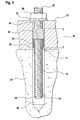
  • the armature 10 according to the invention shown in FIG. 1 has an anchor rod 12 a thread 14.
  • One end 16 of the anchor rod 12 is with a wedge-shaped tip Provided. This end 16 will be referred to hereinafter as the front end 16, it is one when setting the anchor 10 in the insertion front end.
  • a rear Area 18 at a distance from a rear end 20 of the anchor rod 12 are two Coil springs 22, 24 by screwing on the thread 14 of the anchor rod 12th placed.
  • the coil springs 22, 24 are clamped by screws against each other (countered) and thereby secured against rotation on the thread 14 of the anchor rod 12.
  • the rear portion 18 of the anchor rod 12, in which the coil springs 22, 24 are arranged, is anchored anchor 10 from an anchoring ground 26, So for example, from a ceiling, wall or floor before.
  • a nut 28 is screwed onto the anchor rod 12. Under the Nut 28 is a washer 30 is placed.
  • the anchor 10 serves to attach an object to be anchored 32 on the anchoring ground 26.
  • the object to be anchored 32 may, for example, a foot a machine, a console or the like. In the drawing is a fraction of the too anchoring object 32 shown.
  • Anchoring takes place in so-called through-hole mounting.
  • the article 32 to be anchored has a through hole 34, whose diameter is sufficient to the anchor rod 12 with the attached coil springs 22, 24 record.
  • the object to be fastened 32 attached to the anchoring base 26 and there is a hole 36 through the through hole 34 in the object to be fastened 32 passes into the anchoring ground 26 drilled.
  • a mortar 38 for example a one- or multi-component synthetic resin mortar in the hole 36 in the anchoring ground 26 introduced.
  • the armature 10 with its front or insertion 16 ahead through the through hole 34 in the object to be fastened 32 inserted through into the hole 36 in the anchoring base 26. It displaces the anchor rod 12 the mortar, leaving the mortar a gap between the anchor rod 12 and a wall of the hole 36 in the anchoring ground 26 fills out.
  • the coil springs 22, 24 are within the through-hole 34 of the object 32 to be fixed and reduce radial play between the armature 10 and the one to be fastened Item 32.
  • the nut 28 is tightened and to fastened object 32 thereby tensioned against the anchoring ground 26.
  • the armature 10a shown in Figure 2 has an anchor rod 12a, the off originally made of two parts.
  • anchoring area 40 a Reinforcing bar with corresponding projections 42 friction welding at the transition 46th connected to a threaded rod as a threaded portion 44.
  • By the combination two materials, such as stainless steel for the threaded portion 44 and Reinforcing bars for the anchorage area 40, can have optimal properties be achieved with respect to the corrosion and anchoring properties.

Landscapes

  • Engineering & Computer Science (AREA)
  • General Engineering & Computer Science (AREA)
  • Mechanical Engineering (AREA)
  • On-Site Construction Work That Accompanies The Preparation And Application Of Concrete (AREA)
  • Reinforcement Elements For Buildings (AREA)
  • Joining Of Building Structures In Genera (AREA)

Abstract

Die Erfindung betrifft einen Anker (10) zur Verankerung mit Mörtel 38. Die Erfindung schlägt vor, zwei gegeneinander gespannte Schraubenfedern (22, 24) auf die Gewindestange (12) aufzuschrauben und zur Drehsicherung gegeneinander zu spannen (kontern). Die Schraubenfedern (22, 24) sind in einem hinteren Bereich (18) der Ankerstange (12) angeordnet, der bei verankerter Ankerstange (12) aus einem Verankerungsgrund (26) vorsteht. Die Schraubenfedern (22, 24) verkleinern ein Spiel zwischen dem Anker (10) und einem zu befestigenden Gegenstand 32. <IMAGE>

Description

Die Erfindung betrifft einen Anker zur Verankerung mit Mörtel mit den Merkmalen des Oberbegriffs des Anspruchs 1.
Derartige Anker sind an sich bekannt. Sie weisen eine Ankerstange auf, die mit Mörtel, beispielsweise einem Kunstharzmörtel, in einem Loch in einem Verankerungsgrund verankerbar sind. Der Verankerungsgrund kann eine Wand, Decke oder Boden sein. Das Gewinde muss nicht auf der vollen Länge der Ankerstange ausgebildet sein, es genügt ein Gewinde in einem hinteren Bereich der Ankerstange, der bei verankerter Ankerstange aus dem Verankerungsgrund vorsteht. Auf den aus dem Verankerungsgrund vorstehenden hinteren Bereich der Ankerstange kann ein ein Durchgangsloch aufweisender Gegenstand aufgesetzt und mit einer auf das Gewinde der Ankerstange aufgeschraubten Mutter festgespannt werden (sog. Vorsteckmontage, bei der der Anker im Verankerungsgrund verankert und anschließend der zu befestigende Gegenstand angebracht wird). Für eine sog. Durchsteckmontage eignen sich die bekannten Anker nicht. Bei der Durchsteckmontage wird durch das Durchgangsloch im zu befestigenden Gegenstand ein Bohrloch im Verankerungsgrund angebracht und anschließend der Anker durch das zu befestigende Bauteil hindurch in das Bohrloch im Verankerungsgrund eingebracht. Für die Verankerung mit Mörtel ist das Bohrloch im Verankerungsgrund mit ausreichendem Übermaß vorzusehen, es weist deswegen einen größeren Durchmesser auf als üblicherweise das Durchgangsloch im zu befestigenden Gegenstand. Es lässt sich deswegen das Bohrloch nicht durch den zu befestigenden Gegenstand hindurch im Verankerungsgrund anbringen. Ein größeres Durchgangsloch im zu befestigenden Gegenstand hätte ein unerwünscht großes Spiel zwischen dem zu befestigenden Gegenstand und dem Anker zur Folge.
Der Erfindung liegt die Aufgabe zugrunde, einen Anker der vorstehend erläuterten Art vorzuschlagen, der für eine Durchsteckmontage geeignet ist.
Diese Aufgabe wird erfindungsgemäß durch die Merkmale des Anspruchs 1 gelöst. Der erfindungsgemäße Anker weist einen schraubenförmig gewundenen Draht auf, der auf das Gewinde der Ankerstange aufgesetzt ist und nach Art einer Schraubverbindung in das Gewinde der Ankerstange eingreift. Der Draht ist im hinteren Bereich der Ankerstange angeordnet, der bei verankerter Ankerstange aus dem Verankerungsgrund vorsteht. Der auf die Ankerstange aufgesetzte Draht vergrößert den Durchmesser des Ankers in dem Bereich, der sich bei am Verankerungsgrund befestigtem Gegenstand im Durchgangsloch des befestigten Gegenstandes befindet. Dadurch kann das Durchgangsloch im zu befestigenden Gegenstand einen gleich großen oder größeren Durchmesser wie das Loch im Verankerungsgrund aufweisen. Der im Durchgangsloch des zu befestigenden Gegenstands um die Ankerstange gewundene Draht verkleinert ein Spiel zwischen der Ankerstange und dem zu befestigenden Gegenstand auf ein übliches und tolerierbares Maß.
Die Erfindung hat den Vorteil, dass sie eine Durchsteckmontage ermöglicht. Ein Loch zum Verankern des Ankers kann durch ein Durchgangsloch im zu befestigenden Gegenstand hindurch im Verankerungsgrund angebracht werden. Ein Bohrer wird beim Bohren in den Verankerungsgrund vom Durchgangsloch des zu befestigenden Gegenstandes geführt und kann nicht soweit verlaufen, dass das Durchgangsloch im zu befestigenden Gegenstand das Loch im Verankerungsgrund nicht mehr überdeckt und die Ankerstange nicht durch das Durchgangsloch in das Loch im Verankerungsgrund einbringbar ist. Weiterer Vorteil der Durchsteckmontage ist ihr im Vergleich zur Vorsteckmontage geringerer Aufwand.
Der Draht muss nicht zwingend aus Metall bestehen. Es ist beispielsweise auch ein Kunststoff verwendbar, der schraubenförmige Windungen wie eine Schraubenfeder aufweist. Auch Derartiges soll als Draht im Sinne der Erfindung verstanden werden. Ein Querschnitt des Drahts kann rund oder beispielsweise auch drei- oder viereckig sein.
Der Draht kann beispielsweise eine Schraubenfeder sein. Dies hat den Vorteil, dass er als Massenprodukt preisgünstig erhältlich ist.
Eine Ausgestaltung der Erfindung sieht vor, dass der Draht klemmend auf dem Gewinde der Ankerstange sitzt, er weist also ein Untermaß auf und wird beim Aufschrauben auf das Gewinde der Ankerstange elastisch und/oder plastisch aufgeweitet. Dies vermeidet ein Verdrehen des Drahts auf der Ankerstange, wenn die Ankerstange drehend in den Verankerungsgrund eingebracht wird. Ein Verdrehen des Drahts auf der Ankerstange hätte eine Axialverschiebung des Drahts auf der Ankerstange zur Folge und ist deswegen unerwünscht.
Eine andere Möglichkeit einer Drehsicherung ist das Aufschrauben zweier schraubenförmig gewundener Drähte auf das Gewinde der Ankerstange, wobei die Drähte durch Drehen gegeneinander miteinander verspannt (gekontert) werden. Zum Kontern sieht eine Ausgestaltung der Erfindung plan ausgebildete, aneinander anliegende Stirnflächen der Drähte vor.
Um die Haltewerte des Ankers zu verbessern, sieht eine Ausführungsform vor, dass die Ankerstange in ihrem Verankerungsbereich Vorsprünge nach Art von Bewehrungsstäben aufweist. Auszugversuche haben gezeigt, dass hierdurch gegenüber einem durchgehenden Gewinde deutliche Verbesserungen erzielbar sind. Vorzugsweise wird dabei ein Stück eines Bewehungsstabs aus Betonstabstahl mit einem Gewindestab verbunden und somit die Ankerstange aus zwei Teilen gebildet. Während sich der Betonstabstahl vor allem durch seine Elastizität positiv für die Verankerung auswirkt, gewährleistet ein Gewindestab beispielsweise aus Edelstahl die Korrosionsbeständigkeit des Ankers. Zum Verbinden der beiden Teile eignet sich sowohl das Reibschweißen als auch umformende Verfahren, beispielsweise Rollen oder Börteln.
Die Erfindung wird nachfolgend anhand eines in der Zeichnung dargestellten Ausführungsbeispiels näher erläutert. Es zeigen:
Figur 1
einen erfindungsgemäßen Anker in Seitenansicht;
Figur 2
ein weiteres Ausführungsbeispiel des Ankers in Seitenansicht.
Der in Figur 1 dargestellte, erfindungsgemäße Anker 10 weist eine Ankerstange 12 mit einem Gewinde 14 auf. Ein Ende 16 der Ankerstange 12 ist mit einer keilförmigen Spitze versehen. Dieses Ende 16 wird nachfolgend als vorderes Ende 16 bezeichnet werden, es ist ein beim Setzen des Ankers 10 in Einführrichtung vorderes Ende. In einem hinteren Bereich 18 mit Abstand von einem hinteren Ende 20 der Ankerstange 12 sind zwei Schraubenfedern 22, 24 durch Aufschrauben auf das Gewinde 14 der Ankerstange 12 aufgesetzt. Die Schraubenfedern 22, 24 sind durch Schrauben gegeneinander gespannt (gekontert) und dadurch gegen Drehen auf dem Gewinde 14 der Ankerstange 12 gesichert. Der hintere Bereich 18 der Ankerstange 12, in dem die Schraubenfedern 22, 24 angeordnet sind, steht bei verankertem Anker 10 aus einem Verankerungsgrund 26, also beispielsweise aus einer Decke, Wand oder einem Boden, vor.
Am hinteren Ende 20 ist eine Mutter 28 auf die Ankerstange 12 aufgeschraubt. Unter die Mutter 28 ist eine Unterlegscheibe 30 gelegt.
Der Anker 10 dient zur Befestigung eines zu verankernden Gegenstandes 32 am Verankerungsgrund 26. Der zu verankernde Gegenstand 32 kann beispielsweise ein Fuß einer Maschine, eine Konsole oder dgl. sein. In der Zeichnung ist ein Bruchteil des zu verankernden Gegenstandes 32 dargestellt. Die Verankerung erfolgt in sog. Durchsteckmontage. Der zu verankernde Gegenstand 32 weist ein Durchgangsloch 34 auf, dessen Durchmesser ausreicht, um die Ankerstange 12 mit den aufgesetzten Schraubenfedern 22, 24 aufzunehmen. Zur Befestigung wird der zu befestigende Gegenstand 32 am Verankerungsgrund 26 angesetzt und es wird ein Loch 36 durch das Durchgangsloch 34 im zu befestigenden Gegenstand 32 hindurch in den Verankerungsgrund 26 gebohrt. Da das Durchgangsloch 34 im zu befestigenden Gegenstand 32 einen Bohrer beim Bohren des Lochs 36 in den Verankerungsgrund 26 führt ist sichergestellt, dass das Durchgangsloch 34 im zu befestigenden Gegenstand 32 das Loch 36 im Verankerungsgrund 26 überdeckt und der Anker 10 durch das Durchgangsloch 34 im zu befestigenden Gegenstand 32 hindurch in das Loch 36 im Verankerungsgrund 26 gesteckt werden kann.
Nach dem Bohren des Lochs 36 in den Verankerungsgrund 26 wird ein Mörtel 38, beispielsweise ein Ein- oder Mehrkomponenten-Kunstharzmörtel in das Loch 36 im Verankerungsgrund 26 eingebracht. Anschließend wird der Anker 10 mit seinem vorderen oder Einführende 16 voran durch das Durchgangsloch 34 im zu befestigenden Gegenstand 32 hindurch in das Loch 36 im Verankerungsgrund 26 eingebracht. Dabei verdrängt die Ankerstange 12 den Mörtel, so dass der Mörtel einen Zwischenraum zwischen der Ankerstange 12 und einer Wandung des Lochs 36 im Verankerungsgrund 26 ausfüllt. Der hintere Bereich 18 des Ankers 10, in dem sich die Schraubenfedern 22, 24 befinden, steht aus dem Verankerungsgrund 26 vor. Die Schraubenfedern 22, 24 befinden sich innerhalb des Durchgangslochs 34 des zu befestigenden Gegenstands 32 und verringern ein Radialspiel zwischen dem Anker 10 und dem zu befestigenden Gegenstand 32.
Nach dem Aushärten des Mörtels 38 wird die Mutter 28 angezogen und der zu befestigende Gegenstand 32 dadurch gegen den Verankerungsgrund 26 gespannt.
Wird der Anker 10 ohne Drehung in das Loch 36 im Verankerungsgrund 26 eingebracht, ist eine Drehsicherung der Schraubenfedern 22, 24 nicht erforderlich. In diesem Fall genügt eine der beiden Schraubenfedern 22, 24, die zweite, zur Konterung vorgesehene Schraubenfeder 22, 24 kann weggelassen werden.
Der in Figur 2 dargestellte Anker 10a weist eine Ankerstange 12a auf, die aus ursprünglich zwei Teilen hergestellt ist. Dabei wird als Verankerungsbereich 40 ein Bewehrungsstab mit entsprechenden Vorsprüngen 42 reibschweißend am Übergang 46 mit einem Gewindestab als Gewindebereich 44 verbunden. Durch die Kombination zweier Werkstoffe, beispielsweise Edelstahl für den Gewindebereich 44 und Betonstabstahl für den Verankerungsbereich 40, können optimale Eigenschaften bezüglich der Korrosions- und Verankerungseigenschaften erzielt werden.
Claims (8)

  1. Anker zur Verankerung mit Mörtel, mit einer ein Gewinde aufweisenden Ankerstange, dadurch gekennzeichnet, dass ein schraubenförmig gewundener Draht (22) auf die Ankerstange (12, 12a) aufgesetzt ist und nach Art einer Schraubverbindung in das Gewinde (14) der Ankerstange (12, 12a) eingreift, und dass der Draht (22) mit Abstand von einem hinteren Ende (20) der Ankerstange (12, 12a) in einem hinteren Bereich (18) der Ankerstange (12, 12a) angeordnet ist, der bei verankerter Ankerstange (12, 12a) aus einem Verankerungsgrund (26) vorsteht.
  2. Anker nach Anspruch 1, dadurch gekennzeichnet, dass der Draht (22) eine Schraubenfeder ist.
  3. Anker nach Anspruch 1, dadurch gekennzeichnet, dass der Draht (22) klemmend auf dem Gewinde (14) der Ankerstange (12, 12a) sitzt.
  4. Anker nach Anspruch 1, dadurch gekennzeichnet, dass zwei schraubenförmig gewundene Drähte (22, 24) axial aneinander anliegend auf das Gewinde (14) der Ankerstange (12) aufgesetzt und miteinander verspannt (gekontert) sind.
  5. Anker nach Anspruch 4, dadurch gekennzeichnet, dass die an einander anliegenden Stirnflächen der Drähte (22, 24) plan sind.
  6. Anker nach Anspruch 1, dadurch gekennzeichnet, dass die Ankerstange (12a) in ihrem Verankerungsbereich (40) Vorsprünge (42) nach Art von Bewehrungsstäben aufweist.
  7. Anker nach Anspruch 6, dadurch gekennzeichnet, dass die Ankerstange (12a) in ihrem Verankerungsbereich (40) aus Betonstabstahl und in ihrem Gewindebereich (44) aus Edelstahl besteht.
  8. Anker nach Anspruch 7, dadurch gekennzeichnet, dass der Verankerungsbereich (40) mit dem Gewindebereich (44) reibgeschweißt verbunden ist.
EP02017905A 2001-08-16 2002-08-09 Anker zur Verankerung mit Mörtel Withdrawn EP1302675A1 (de)

Applications Claiming Priority (2)

Application Number Priority Date Filing Date Title
DE20113588U DE20113588U1 (de) 2001-08-16 2001-08-16 Anker zur Verankerung mit Mörtel
DE20113588U 2001-08-16

Publications (1)

Publication Number Publication Date
EP1302675A1 true EP1302675A1 (de) 2003-04-16

Family

ID=7960597

Family Applications (1)

Application Number Title Priority Date Filing Date
EP02017905A Withdrawn EP1302675A1 (de) 2001-08-16 2002-08-09 Anker zur Verankerung mit Mörtel

Country Status (2)

Country Link
EP (1) EP1302675A1 (de)
DE (1) DE20113588U1 (de)

Citations (5)

* Cited by examiner, † Cited by third party
Publication number Priority date Publication date Assignee Title
CH169273A (de) * 1933-08-29 1934-05-31 Abel Wilhelm Vorrichtung zur lösbaren Verbindung zweier miteinander zu verschraubender Holzteile.
FR1038680A (fr) * 1951-04-26 1953-09-30 Organe d'assemblage et de fixation
DE2452564A1 (de) * 1974-11-06 1976-05-13 Biriz Oemer Acar Dipl Bau Ing Bolzen und schraubenfeder duebel
US3967525A (en) * 1974-01-02 1976-07-06 Wej-It Expansion Products, Inc. Spring action expansion bolt
DE4226788A1 (de) * 1992-08-13 1994-02-17 Fischer Artur Werke Gmbh Anker zur Verankerung mittels einer Verbundmasse

Family Cites Families (2)

* Cited by examiner, † Cited by third party
Publication number Priority date Publication date Assignee Title
GB191508887A (en) * 1915-06-16 1916-06-08 Gurdon Saltonstall Mumford Improvements in and relating to Devices for use in Concrete Construction and for Concrete and like Structures.
DE29512497U1 (de) * 1995-08-03 1995-11-16 Reimesch, Gert, Dr.med.stom., 96337 Ludwigsstadt Dübel

Patent Citations (5)

* Cited by examiner, † Cited by third party
Publication number Priority date Publication date Assignee Title
CH169273A (de) * 1933-08-29 1934-05-31 Abel Wilhelm Vorrichtung zur lösbaren Verbindung zweier miteinander zu verschraubender Holzteile.
FR1038680A (fr) * 1951-04-26 1953-09-30 Organe d'assemblage et de fixation
US3967525A (en) * 1974-01-02 1976-07-06 Wej-It Expansion Products, Inc. Spring action expansion bolt
DE2452564A1 (de) * 1974-11-06 1976-05-13 Biriz Oemer Acar Dipl Bau Ing Bolzen und schraubenfeder duebel
DE4226788A1 (de) * 1992-08-13 1994-02-17 Fischer Artur Werke Gmbh Anker zur Verankerung mittels einer Verbundmasse

Also Published As

Publication number Publication date
DE20113588U1 (de) 2003-01-02

Similar Documents

Publication Publication Date Title
DE4310796C2 (de) Spreizanker
DE69506479T2 (de) Befestigungsvorrichtung
DE3100730A1 (de) Verfahren zum stuetzen und/oder verfestigen von hohlraumwaenden im tief-, berg- und tunnelbau, vorrichtung zum durchfuehren des verfahrens und in einem bohrloch der hohlraumwand sitzender verfestigungsanker
EP1899613B1 (de) Schraubanker
EP2992226B1 (de) Verankerungssystem
EP1076185A2 (de) Schraubanker
EP1233194A2 (de) Betonschraube
EP2354567B1 (de) Verbundankerschraube
DE19642914C2 (de) Dübel
DE10129441A1 (de) Verbundanker
DE10327312A1 (de) Abstandelement
DE102006017459A1 (de) Abstandshalter für die Befestigung eines Gegenstandes an einem eine Dämmschicht aufweisenden Untergrund
EP1302675A1 (de) Anker zur Verankerung mit Mörtel
EP0250783B1 (de) Spreizdübel
DE3620573A1 (de) Vorrichtung zum befestigen eines gegenstandes an einer wand oder dgl.
DE2164666A1 (de) Ankerbolzen
DE3215115C2 (de) Vorrichtung zur Befestigung von Fassadenplatten vor Beton- bzw. Steinwänden
DE4032682C2 (de) Gebirgsanker
DE10161426A1 (de) Verankerung für verspannte Konstruktionen
EP1036948B1 (de) Dübel
DE4343935C2 (de) Plattenbefestigungselement
DE29512497U1 (de) Dübel
DE3631544A1 (de) Verfahren zum verankern von bauteilen in insbesondere beton
EP0580998A1 (de) Metallspreizdübel
EP2894354B1 (de) Befestigungselement

Legal Events

Date Code Title Description
PUAI Public reference made under article 153(3) epc to a published international application that has entered the european phase

Free format text: ORIGINAL CODE: 0009012

AK Designated contracting states

Designated state(s): AT BE BG CH CY CZ DE DK EE ES FI FR GB GR IE IT LI LU MC NL PT SE SK TR

AX Request for extension of the european patent

Extension state: AL LT LV MK RO SI

17P Request for examination filed

Effective date: 20030718

AKX Designation fees paid

Designated state(s): AT BE BG CH CY CZ DE DK EE ES FI FR GB GR IE IT LI LU MC NL PT SE SK TR

RAP1 Party data changed (applicant data changed or rights of an application transferred)

Owner name: FISCHERWERKE GMBH & CO. KG

17Q First examination report despatched

Effective date: 20080826

STAA Information on the status of an ep patent application or granted ep patent

Free format text: STATUS: THE APPLICATION IS DEEMED TO BE WITHDRAWN

18D Application deemed to be withdrawn

Effective date: 20100302