EP1302641A2 - Drosselklappenanordnung für Brennkraftmaschinen - Google Patents
Drosselklappenanordnung für Brennkraftmaschinen Download PDFInfo
- Publication number
- EP1302641A2 EP1302641A2 EP02016455A EP02016455A EP1302641A2 EP 1302641 A2 EP1302641 A2 EP 1302641A2 EP 02016455 A EP02016455 A EP 02016455A EP 02016455 A EP02016455 A EP 02016455A EP 1302641 A2 EP1302641 A2 EP 1302641A2
- Authority
- EP
- European Patent Office
- Prior art keywords
- throttle valve
- rounded
- air duct
- drive shaft
- edge
- Prior art date
- Legal status (The legal status is an assumption and is not a legal conclusion. Google has not performed a legal analysis and makes no representation as to the accuracy of the status listed.)
- Granted
Links
- 238000002485 combustion reaction Methods 0.000 title claims description 3
- 230000007704 transition Effects 0.000 claims abstract description 14
- 238000004519 manufacturing process Methods 0.000 claims description 9
- 238000004049 embossing Methods 0.000 claims description 4
- 238000000034 method Methods 0.000 claims description 4
- 238000005520 cutting process Methods 0.000 claims description 2
- 238000003801 milling Methods 0.000 description 4
- 230000000694 effects Effects 0.000 description 1
- 239000012530 fluid Substances 0.000 description 1
- 239000002184 metal Substances 0.000 description 1
- 230000000717 retained effect Effects 0.000 description 1
- XLYOFNOQVPJJNP-UHFFFAOYSA-N water Substances O XLYOFNOQVPJJNP-UHFFFAOYSA-N 0.000 description 1
Images

Classifications
-
- F—MECHANICAL ENGINEERING; LIGHTING; HEATING; WEAPONS; BLASTING
- F02—COMBUSTION ENGINES; HOT-GAS OR COMBUSTION-PRODUCT ENGINE PLANTS
- F02D—CONTROLLING COMBUSTION ENGINES
- F02D9/00—Controlling engines by throttling air or fuel-and-air induction conduits or exhaust conduits
- F02D9/08—Throttle valves specially adapted therefor; Arrangements of such valves in conduits
- F02D9/10—Throttle valves specially adapted therefor; Arrangements of such valves in conduits having pivotally-mounted flaps
- F02D9/1005—Details of the flap
- F02D9/101—Special flap shapes, ribs, bores or the like
- F02D9/1015—Details of the edge of the flap, e.g. for lowering flow noise or improving flow sealing in closed flap position
Definitions
- the invention relates to a throttle valve assembly for internal combustion engines a housing which has an air duct in which a disc-shaped throttle valve is pivotally mounted on a drive shaft, the throttle valve at least one hole for a fastener and at least partially has rounded outer surface.
- Such a throttle valve is disclosed, for example, in DE 198 02 673 A1 and has measures there which are intended to reduce the leakage air. This consist of a circumferentially rounded lateral surface of the throttle valve, which Milling is achieved.
- this object is achieved in that the lateral surface has two partial surfaces and two transition surfaces, the Partial surfaces are arranged symmetrically to the axis of rotation of the throttle valve and which are arranged in the area of the drive shaft, the partial surfaces being two edge pieces have, such that in the closed position of the throttle valve to the air duct wall directed edge piece is rounded.
- An advantageous training of this Throttle valve is that the transition surfaces in relation to the Subareas are small.
- the invention is based on the knowledge that the shape of the throttle valve the part of the side edge which is irrelevant for the tilt-free closing of the throttle valve the flow resistance of the leakage air in the closed position of the throttle valve can influence advantageously without the throttle valve in the open position an additional pressure loss occurs.
- the process for producing the same Throttle valve it has become possible to use the process for producing the same Throttle valve to improve significantly.
- the rounded edges can be produced by milling done by chipless forming. So after initially only the Contour of the partial areas to be rounded is punched out, for example the rounding are produced by embossing, without the throttle valve to be manufactured emerging from the Sheet from which it is punched out is previously removed. Because the Throttle valve with the help of the not yet punched transition surfaces with the Sheet is fixed, it is also possible to drill the holes in the throttle valve in one to punch out another manufacturing step, which leads to the position of the Holes in relation to the outer surface of the throttle valve arranged much more precisely becomes.
- Fig. 1 is a throttle valve assembly 1 with a housing 2, which is an air duct 3 forms, in which a disc-shaped throttle valve 4 with a bore 5 for a fastener 6 is attached to a drive shaft 7, shown schematically. It clearly shows that in the closed position a lateral surface 8 of the Throttle valve 4 abuts an air duct wall 9, whereby the air duct 3 seals becomes.
- Fig. 2 shows the top view of the throttle valve 4 with an axis of rotation 10.
- To the outer surface 8 of the throttle valve 4 include two partial surfaces 11a and 11b and two transition surfaces 12a and 12b, which are each arranged point-symmetrically. It is in 2 clearly shows that the transition surfaces 12a and 12b in relation to the partial areas 11a and 11b are small. The accuracy of the position of the holes 5a and 5b in relation to the partial surfaces 11a and 11b is improved if they are punched out, while the transition surfaces 12a and 12b still with the Sheet from which the throttle valve 4 is punched out are connected.
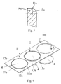
- FIG 3 is a detailed view of the partially rounded throttle valve edge shown how the partial surface 11a is divided into edge pieces 13a and 14a. It is the edge piece 13a is rounded and the edge piece 14a is not rounded. The same is true the partial surface 11b point symmetrical to the partial surface 11a in a rounded edge piece 13b and a non-rounded edge piece 14b divided. This ensures that taking into account manufacturing tolerances and thermal expansion effects rounded edge pieces 13a and 13b in the closed position of the throttle valve 4 without tilting rest on the air duct wall 9. At the same time, the non-rounded increase Edge pieces 14a and 14b the flow resistance of the leakage air.
- the representation of an advantageous method for producing the throttle valve in 4 shows, as in a first step I, the partial surfaces 11a and 11b of the throttle valve 4 can be punched.
- the transition surfaces 12a and 12b are, however not yet punched.
- a second step II the rounded edge pieces 13a and 13b. Because when embossing from two sides one at the same time Embossing can be applied in a single step performed without it being necessary e.g. B. for turning around Sheet metal another step.
- Throttle valve 4 punched out In a final step III Throttle valve 4 punched out. This method avoids that, for example in DE 198 02 673 A 1 the rounding is generated by milling.
Landscapes
- Engineering & Computer Science (AREA)
- Chemical & Material Sciences (AREA)
- Combustion & Propulsion (AREA)
- Mechanical Engineering (AREA)
- General Engineering & Computer Science (AREA)
- Lift Valve (AREA)
Abstract
Description
Claims (3)
- Drosselklappenanordnung (1) für Brennkraftmaschinen mit einem Gehäuse (2), das einen Luftkanal (3) aufweist, in dem eine scheibenförmige Drosselklappe (4) schwenkbar auf einer Antriebswelle (7) gelagert ist, wobei die Drosselklappe (4) mindestens eine Bohrung (5) für ein Befestigungselement (6) und eine zumindest teilweise gerundete Mantelfläche (8) aufweist dadurch gekennzeichnet, dass die Mantelfläche (8) zwei Teilflächen (11a und 11b) und zwei Übergangsflächen (12a und 12b) aufweist, wobei die Teilflächen (11a und 11b) punktsymmetrisch zur Drehachse (10) der Drosselklappe angeordnet sind und die Übergangsflächen (12a und 12b) im Bereich der Antriebswelle (7) angeordnet sind, wobei die Teilflächen (11a und 11b) zwei Randstücke (13 und 14) aufweisen, derart, dass das in Schließstellung der Drosselklappe (4) zur Luftkanalwand (9) gerichtete Randstück (13) abgerundet ist.
- Drosselklappenanordnung nach Anspruch 1 dadurch gekennzeichnet, dass die Übergangsflächen (12a und 12b) im Verhältnis zu den Teilflächen (11a und 11b) klein sind.
- Verfahren zur Herstellung der Drosselklappe nach Anspruch 1 oder 2 dadurch gekennzeichnet, dass in einem ersten Schritt (I) eine Kontur (15) der Drosselklappe (4) mit Ausnahme der Übergangsflächen (12a und 12b) gestanzt wird, in einem zweiten Schritt (II) die abgerundeten Randstücke (13a und 13b) durch ein spanloses Umformverfahren, insbesondere Prägen, erzeugt werden und in einem letzten Schritt (III) die Drosselklappe (4) ausgestanzt wird.
Applications Claiming Priority (2)
| Application Number | Priority Date | Filing Date | Title |
|---|---|---|---|
| DE10150516 | 2001-10-12 | ||
| DE2001150516 DE10150516A1 (de) | 2001-10-12 | 2001-10-12 | Drosselklappenanordnung für Brennkraftmaschinen |
Publications (3)
| Publication Number | Publication Date |
|---|---|
| EP1302641A2 true EP1302641A2 (de) | 2003-04-16 |
| EP1302641A3 EP1302641A3 (de) | 2004-06-30 |
| EP1302641B1 EP1302641B1 (de) | 2008-12-10 |
Family
ID=7702357
Family Applications (1)
| Application Number | Title | Priority Date | Filing Date |
|---|---|---|---|
| EP02016455A Expired - Lifetime EP1302641B1 (de) | 2001-10-12 | 2002-07-23 | Drosselklappenanordnung für Brennkraftmaschinen |
Country Status (3)
| Country | Link |
|---|---|
| EP (1) | EP1302641B1 (de) |
| DE (2) | DE10150516A1 (de) |
| ES (1) | ES2314013T3 (de) |
Families Citing this family (2)
| Publication number | Priority date | Publication date | Assignee | Title |
|---|---|---|---|---|
| DE10328246B4 (de) * | 2003-06-24 | 2007-04-26 | Pierburg Gmbh | Kraftfahrzeugventil |
| DE102007013782B3 (de) * | 2007-03-22 | 2008-09-25 | Pierburg Gmbh | Verfahren zur Herstellung einer Klappenvorrichtung für Verbrennungskraftmaschinen sowie derartige Klappenvorrichtung |
Citations (1)
| Publication number | Priority date | Publication date | Assignee | Title |
|---|---|---|---|---|
| DE19802673A1 (de) | 1998-01-24 | 1999-07-29 | Pierburg Ag | Drosselklappenstutzen für Brennkraftmaschinen |
Family Cites Families (7)
| Publication number | Priority date | Publication date | Assignee | Title |
|---|---|---|---|---|
| GB119180A (en) * | 1918-02-05 | 1918-09-26 | Andrew Eadie Cook | Carburettor for Internal Combustion Engines. |
| DE1600880A1 (de) * | 1951-01-28 | 1971-09-16 | Pierburg Kg A | Drosselklappe |
| US3596493A (en) * | 1967-09-15 | 1971-08-03 | Maurice Lachaussee | Stamping process for metal objects |
| DK11278A (da) * | 1978-01-10 | 1979-07-11 | Knudsen A S | Oprivningslukke |
| JPS5656938A (en) * | 1979-10-15 | 1981-05-19 | Nissan Motor Co Ltd | Apparatus for detecting opening of throttle valve |
| FR2674600B1 (fr) * | 1991-03-27 | 1993-07-09 | Solex | Procede de fabrication de papillon d'etranglement utilisable dans une installation d'alimentation en combustible. |
| JPH10103087A (ja) * | 1996-10-01 | 1998-04-21 | Mitsubishi Electric Corp | 制御弁装置 |
-
2001
- 2001-10-12 DE DE2001150516 patent/DE10150516A1/de not_active Withdrawn
-
2002
- 2002-07-23 ES ES02016455T patent/ES2314013T3/es not_active Expired - Lifetime
- 2002-07-23 DE DE50213097T patent/DE50213097D1/de not_active Expired - Lifetime
- 2002-07-23 EP EP02016455A patent/EP1302641B1/de not_active Expired - Lifetime
Patent Citations (1)
| Publication number | Priority date | Publication date | Assignee | Title |
|---|---|---|---|---|
| DE19802673A1 (de) | 1998-01-24 | 1999-07-29 | Pierburg Ag | Drosselklappenstutzen für Brennkraftmaschinen |
Also Published As
| Publication number | Publication date |
|---|---|
| DE10150516A1 (de) | 2003-04-17 |
| EP1302641B1 (de) | 2008-12-10 |
| ES2314013T3 (es) | 2009-03-16 |
| DE50213097D1 (de) | 2009-01-22 |
| EP1302641A3 (de) | 2004-06-30 |
Similar Documents
| Publication | Publication Date | Title |
|---|---|---|
| WO1984004566A1 (fr) | Raccord pour conduit d'injection | |
| EP2029318A1 (de) | Verfahren zur herstellung eines einteiligen kolbens sowie damit hergestellter kolben | |
| DE102009009252B4 (de) | Hydraulischer Nockenwellenversteller mit axialer Verschlussschraube | |
| EP1636474A2 (de) | Verfahren zur herstellung eines einteiligen kolbens für einen verbrennungsmotor | |
| DE2913575A1 (de) | Reedventil und ein reedventil enthaltender kompressor | |
| WO2006087186A1 (de) | Dichtungseinrichtung für einen kraftstoffinjektor sowie verfahren zum abdichten | |
| DE3905636A1 (de) | Schieberventil | |
| DE19751293A1 (de) | Einschichtige oder mehrschichtige Metallzylinderkopfdichtung und Verfahren zu ihrer Herstellung | |
| DE2133422C3 (de) | Mehrstufiges Druckreduzierventil | |
| DE102006011580B3 (de) | Drehschieberorgan zur pneumatischen Steuerung | |
| EP1819922A1 (de) | Zweiteiliger kolben für einen verbrennungsmotor | |
| WO2008043754A1 (de) | Drosselklappenstutzen | |
| DE60217064T2 (de) | Kraftstoff-einspritzdüse | |
| EP1302641A2 (de) | Drosselklappenanordnung für Brennkraftmaschinen | |
| WO2007031109A1 (de) | Kolben, insbesondere kühlkanalkolben einer brennkraftmaschine mit zumindest drei reibschweisszonen | |
| DE69405073T2 (de) | Hydraulische Antriebseinheit mit Dämpfer für Ein- oder Auslassventil | |
| DE19956929B4 (de) | Öldruck-Regelventil | |
| EP1918592B2 (de) | Dichtringanordnung mit Dichtung, integrierter Endlagendämpfung und Deckel, für einen Pneumatikzylinder | |
| DE4410288C1 (de) | Ventilbetätigungsvorrichtung für eine Brennkraftmaschine | |
| DE925477C (de) | Mehrstufige Regelduese | |
| DE102004018386A1 (de) | Verfahren zum Einstellen des Kugelhubs eines Ventilspielausgleichselements | |
| EP3762638A1 (de) | Plattenventil sowie verfahren zum betrieb desselben | |
| DE2548049A1 (de) | Verfahren zur befestigung eines kolbens auf einer kolbenstange, insbesondere von hydraulischen teleskopdaempfern fuer kraftfahrzeuge | |
| DE60314226T2 (de) | Sprühmusterelement und Kraftstoffeinspritzventil mit demselben | |
| EP0286810B1 (de) | Verfahren zum Herstellen eines Ventils, insbesondere eines thermostatischen Ventils |
Legal Events
| Date | Code | Title | Description |
|---|---|---|---|
| PUAI | Public reference made under article 153(3) epc to a published international application that has entered the european phase |
Free format text: ORIGINAL CODE: 0009012 |
|
| 17P | Request for examination filed |
Effective date: 20020723 |
|
| AK | Designated contracting states |
Designated state(s): AT BE BG CH CY CZ DE DK EE ES FI FR GB GR IE IT LI LU MC NL PT SE SK TR |
|
| AX | Request for extension of the european patent |
Extension state: AL LT LV MK RO SI |
|
| PUAL | Search report despatched |
Free format text: ORIGINAL CODE: 0009013 |
|
| AK | Designated contracting states |
Kind code of ref document: A3 Designated state(s): AT BE BG CH CY CZ DE DK EE ES FI FR GB GR IE IT LI LU MC NL PT SE SK TR |
|
| AX | Request for extension of the european patent |
Extension state: AL LT LV MK RO SI |
|
| RIC1 | Information provided on ipc code assigned before grant |
Ipc: 7F 02D 9/10 A Ipc: 7F 16K 1/226 B |
|
| AKX | Designation fees paid |
Designated state(s): DE ES FR GB IT |
|
| 17Q | First examination report despatched |
Effective date: 20070920 |
|
| GRAP | Despatch of communication of intention to grant a patent |
Free format text: ORIGINAL CODE: EPIDOSNIGR1 |
|
| GRAS | Grant fee paid |
Free format text: ORIGINAL CODE: EPIDOSNIGR3 |
|
| GRAS | Grant fee paid |
Free format text: ORIGINAL CODE: EPIDOSNIGR3 |
|
| GRAA | (expected) grant |
Free format text: ORIGINAL CODE: 0009210 |
|
| AK | Designated contracting states |
Kind code of ref document: B1 Designated state(s): DE ES FR GB IT |
|
| REG | Reference to a national code |
Ref country code: GB Ref legal event code: FG4D Free format text: NOT ENGLISH |
|
| REF | Corresponds to: |
Ref document number: 50213097 Country of ref document: DE Date of ref document: 20090122 Kind code of ref document: P |
|
| REG | Reference to a national code |
Ref country code: ES Ref legal event code: FG2A Ref document number: 2314013 Country of ref document: ES Kind code of ref document: T3 |
|
| PLBE | No opposition filed within time limit |
Free format text: ORIGINAL CODE: 0009261 |
|
| STAA | Information on the status of an ep patent application or granted ep patent |
Free format text: STATUS: NO OPPOSITION FILED WITHIN TIME LIMIT |
|
| 26N | No opposition filed |
Effective date: 20090911 |
|
| GBPC | Gb: european patent ceased through non-payment of renewal fee |
Effective date: 20090723 |
|
| PG25 | Lapsed in a contracting state [announced via postgrant information from national office to epo] |
Ref country code: GB Free format text: LAPSE BECAUSE OF NON-PAYMENT OF DUE FEES Effective date: 20090723 |
|
| REG | Reference to a national code |
Ref country code: ES Ref legal event code: FD2A Effective date: 20090724 |
|
| PG25 | Lapsed in a contracting state [announced via postgrant information from national office to epo] |
Ref country code: ES Free format text: LAPSE BECAUSE OF NON-PAYMENT OF DUE FEES Effective date: 20090724 |
|
| PGFP | Annual fee paid to national office [announced via postgrant information from national office to epo] |
Ref country code: FR Payment date: 20100802 Year of fee payment: 9 Ref country code: IT Payment date: 20100729 Year of fee payment: 9 |
|
| REG | Reference to a national code |
Ref country code: FR Ref legal event code: ST Effective date: 20120330 |
|
| PG25 | Lapsed in a contracting state [announced via postgrant information from national office to epo] |
Ref country code: FR Free format text: LAPSE BECAUSE OF NON-PAYMENT OF DUE FEES Effective date: 20110801 |
|
| PG25 | Lapsed in a contracting state [announced via postgrant information from national office to epo] |
Ref country code: IT Free format text: LAPSE BECAUSE OF NON-PAYMENT OF DUE FEES Effective date: 20110723 |
|
| PGFP | Annual fee paid to national office [announced via postgrant information from national office to epo] |
Ref country code: DE Payment date: 20160721 Year of fee payment: 15 |
|
| REG | Reference to a national code |
Ref country code: DE Ref legal event code: R119 Ref document number: 50213097 Country of ref document: DE |
|
| PG25 | Lapsed in a contracting state [announced via postgrant information from national office to epo] |
Ref country code: DE Free format text: LAPSE BECAUSE OF NON-PAYMENT OF DUE FEES Effective date: 20180201 |