EP0286810B1 - Verfahren zum Herstellen eines Ventils, insbesondere eines thermostatischen Ventils - Google Patents
Verfahren zum Herstellen eines Ventils, insbesondere eines thermostatischen Ventils Download PDFInfo
- Publication number
- EP0286810B1 EP0286810B1 EP88102854A EP88102854A EP0286810B1 EP 0286810 B1 EP0286810 B1 EP 0286810B1 EP 88102854 A EP88102854 A EP 88102854A EP 88102854 A EP88102854 A EP 88102854A EP 0286810 B1 EP0286810 B1 EP 0286810B1
- Authority
- EP
- European Patent Office
- Prior art keywords
- valve
- closure member
- coated
- valve closure
- elastic material
- Prior art date
- Legal status (The legal status is an assumption and is not a legal conclusion. Google has not performed a legal analysis and makes no representation as to the accuracy of the status listed.)
- Expired - Lifetime
Links
Images
Classifications
-
- F—MECHANICAL ENGINEERING; LIGHTING; HEATING; WEAPONS; BLASTING
- F16—ENGINEERING ELEMENTS AND UNITS; GENERAL MEASURES FOR PRODUCING AND MAINTAINING EFFECTIVE FUNCTIONING OF MACHINES OR INSTALLATIONS; THERMAL INSULATION IN GENERAL
- F16K—VALVES; TAPS; COCKS; ACTUATING-FLOATS; DEVICES FOR VENTING OR AERATING
- F16K1/00—Lift valves or globe valves, i.e. cut-off apparatus with closure members having at least a component of their opening and closing motion perpendicular to the closing faces
- F16K1/32—Details
- F16K1/34—Cutting-off parts, e.g. valve members, seats
- F16K1/46—Attachment of sealing rings
-
- F—MECHANICAL ENGINEERING; LIGHTING; HEATING; WEAPONS; BLASTING
- F16—ENGINEERING ELEMENTS AND UNITS; GENERAL MEASURES FOR PRODUCING AND MAINTAINING EFFECTIVE FUNCTIONING OF MACHINES OR INSTALLATIONS; THERMAL INSULATION IN GENERAL
- F16K—VALVES; TAPS; COCKS; ACTUATING-FLOATS; DEVICES FOR VENTING OR AERATING
- F16K1/00—Lift valves or globe valves, i.e. cut-off apparatus with closure members having at least a component of their opening and closing motion perpendicular to the closing faces
- F16K1/32—Details
- F16K1/34—Cutting-off parts, e.g. valve members, seats
Definitions
- the invention relates to a method for producing a valve, in particular a thermoplastic valve, of the type mentioned in the preamble of claim 1.
- Valves are known (DE-A 3 409 505) in which the valve plate consists of at least two components, namely a supporting core e.g. made of metal and a sealing layer surrounding the core made of a relatively soft substance, for which e.g. a rubber-elastic cross-linked polyurethane is used.
- the metallic core is first produced and then the layer intended for covering the core is brought into a liquid or pasty state.
- Valves are also known (EP-A 102 076 in which the valve closure member consists of a double metal disk, the central part of a metal disk being approximately conical in shape and this double metal disk being covered with a rubber sleeve which also covers the side of the valve plate facing away from the valve flow opening The assembly is carried out in such a way that an actuating plunger is first attached to the metal disk and then the rubber sleeve is attached to the metal disk.
- a valve disk is also known (GB-A 1 210 033), which consists of interconnected layers, an upper-side metal layer and a lower-side metal layer being provided, between which there is a layer of elastic material.
- the manufacture of the valve closure member is relatively complex and expensive.
- the metallic plate must first be shaped and processed before the coating can be applied in the liquid or pasty state, which is then to harden. Before application, it may a complex pretreatment of the surface is also necessary, e.g. Sandblasting, pretreatment with etching agents or the like.
- a cost-effective shape suitable for this production method and adapted to the dimensions of the valve closure member to be created e.g. Multiple form.
- the method according to EP-A 102 076 is also complex, since here too the metal disc must first be shaped and machined and connected to the valve tappet used for actuation.
- the sleeve to be applied made of elastic material, must also be manufactured in a separate manufacturing process to the exact shape and size and must be kept ready for mounting on the valve disk.
- the invention has for its object to provide a method for producing a valve, in particular a thermostatic valve, of the type mentioned in the preamble of claim 1, which enables a simpler and less expensive design of the valve closure member.
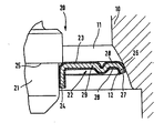
- the drawing shows a schematic, axial longitudinal section of parts of a valve housing with an inserted thermostatic valve.
- a thermostatic valve 20 of a conventional type is arranged, which carries a valve closure member 22 on the outer peripheral surface of a housing section 21. which consists of a valve plate 23 here.
- the valve disk 23 is seated with a cylinder section 24 on the housing section 21 and is supported on an axial shoulder 25 in one direction.
- the valve housing 10 contains an approximately annular valve flow opening 11 which is coaxial with the valve 20 and which here extends approximately in the shape of a truncated cone and forms an inner contact surface 12 against which the valve closure member 22 comes into contact with an associated closing surface 26 in the closed position shown.
- the closing surface 26 is formed here by the outer surface of an outer edge part 27 which is concentric with the cylinder section 24.
- the valve closure member 22 designed in this way is produced from a raw part which is coated at least on the side in the drawing at the top with a layer 28 of an elastic material and which has been processed in this coated state by means of the usual manufacturing methods to form the finished valve closure member 22.
- the raw part here consists, for example, of a metallic carrier 29, which is present in the form of a strip, a plate or a strip material before the valve closure member 22 is manufactured, which at least on one side with the layer 28, in the embodiment shown on both sides with a layer 28, is coated from this elastic material and from which the valve closure member 22 is formed in the finished form shown by means of stamping, embossing, bending, stamping or the like.
- the elastic material of the layer 28 consists in particular of an elastomer, for example rubber, synthetic rubber or the like.
- valve closure member 22 rests in the closed position shown with the outer closing surface 26 on the outer edge part 27 elastically on the inner contact surface 12, the valve closure member 22 being pressed under elastic deformation of the layer 28 in this area and thereby a particularly reliable and good seal in this area is guaranteed.
- valve closure member 22 In the manufacture of the valve closure member 22, one starts from a band-shaped or plate-shaped blank, e.g. consists of a metallic carrier 29, which is coated on both sides with the layer 28 of elastic material. This blank is then processed by punching, embossing, bending, stamping or the like to form the finished valve closure member 22.
- a band-shaped or plate-shaped blank e.g. consists of a metallic carrier 29, which is coated on both sides with the layer 28 of elastic material.
- This blank is then processed by punching, embossing, bending, stamping or the like to form the finished valve closure member 22.
- valve closure member 22 designed in this way makes the valve 20 particularly cost-effective.
Landscapes
- Engineering & Computer Science (AREA)
- General Engineering & Computer Science (AREA)
- Mechanical Engineering (AREA)
- Sliding Valves (AREA)
- Lift Valve (AREA)
Description
- Die Erfindung bezieht sich auf ein Verfahren zum Herstellen eines Ventils, insbesondere eines thermoplastischen Ventils, der im Oberbegriff des Anspruchs 1 genannten Art.
- Es sind Ventile bekannt (DE-A 3 409 505), bei denen die Ventilplatte aus zumindest zwei Komponenten besteht, und zwar einem tragenden Kern z.B. aus Metall und einer den Kern umhüllenden dichtenden Schicht aus einer relativ weichen Substanz, für die z.B. ein gummielastisch vernetztes Polyurethan verwendet wird.
- Bei der Herstellung der Ventilplatte wird zunächst der metallische Kern gefertigt und dann die zur Umhüllung des Kernes bestimmte Schicht in flüssigen oder teigigen Zustand gebracht.
- Diese Schicht, die in Verbindungskontakt mit dem Kern der Ventilplatte gelangt, ist dann in der Lage, bei geregelter Temperatur auszuhärten. Bekannt sind ferner Ventile (EP-A 102 076 bei denen das Ventilverschlußglied aus einer doppelten Metallscheibe besteht, wobei der zentrale Teil einer Metallscheibe etwa kegelförmig gestaltet ist und wobei diese doppelte Metallscheibe mit einer Gummihülle überzogen ist, die die der Ventildurchflußöffnung abgewandte Seite des Ventiltellers mit einem Schulterrand übergreift. Die Montage erfolgt so, daß zunächst ein Betätigungsstößel an der Metallscheibe angebracht und dann die Gummihülle an der Metallscheibe angebracht wird.
- Es ist ferner eine Ventilscheibe bekannt (GB-A 1 210 033), die aus miteinander verbundenen Schichten besteht, wobei eine oberseitige Metallschicht und eine unterseitige Metallschicht vorgesehen sind, zwischen denen sich eine Schicht aus elastischem Material befindet.
- Vor allem bei solchen Ventilen, bei denen das Ventilverschlußglied zumindest auf dem Flächenbereich, der mit der Ventildurchflußöffnung zusammenwirkt, eine Schicht aus elastischem Material trägt, ist die Herstellung des Ventilverschlußgliedes relativ aufwendig und teuer. So muß bei der Methode gemäß DE-A 3 409 505 zunächst der metallische Teller fertig geformt und bearbeitet sein, bevor die Umhüllung in flüssigem oder teigigem Zustand aufgebracht werden kann, die dann aushärten soll. Vor dem Aufbringen ist u.U. auch noch eine aufwendige Vorbehandlung der Oberfläche notwendig, z.B. Sandstrahlen, Vorbehandeln mit Ätzmitteln od. dgl. Außerdem bedarf es einer für diese Herstellungsmethode geeigneten, an die Abmessungen des zu schaffenden Ventilverschlußgliedes angepaßten, kostenaufwendigen Form, z.B. Mehrfachform. Auch die Methode gemäß EP-A 102 076 ist aufwendig, da auch hierbei zunächst die Metallscheibe fertig geformt und bearbeitet und mit dem der Betätigung dienenden Ventilstößel verbunden werden muß.
- Die aufzubringende Hülle aus elastischem Material muß ebenfalls in einem separaten Herstellungsverfahren form- und maßgenau gefertigt werden und zum Aufziehen auf den Ventilteller bereitgehalten werden.
- Der Erfindung liegt die Aufgabe zugrunde, ein Verfahren zum Herstellen eines Ventils, insbesondere eines thermostatischen Ventils, der im Oberbegriff des Anspruchs 1 genannten Art zu schaffen, das eine einfachere und kostengünstigere Gestaltung des Ventilverschlußgliedes ermöglicht.
- Die Aufgabe ist bei einem Verfahren der eingangs genannten Art gemäß der Erfindung durch die Merkmale im Kennzeichnungsteil des Anspruchs 1 gelöst. Dadurch ergibt sich bei der Herstellung des Ventilverschlußgliedes eine wesentliche Vereinfachung und Kostenreduzierung. Es entfällt ein kosten- und zeitaufwendiges separates Beschichten des fertig hergestellten Ventiltellers mit allen eingangs dargelegten Nachteilen, die damit sonst noch verbunden sind.
- Weitere vorteilhafte Ausgestaltungen der Erfindung ergeben sich aus den Ansprüchen 2-4. Auf diese Weise ist eine besonders einfache und kostengünstige Herstellung möglich.
- Weitere Einzelheiten und Vorteile der Erfindung ergeben sich aus der nachfolgenden Beschreibung.
- Der vollständige Wortlaut der Ansprüche ist vorstehend allein zur Vermeidung unnötiger Wiederholungen nicht wiedergegeben, sondern lediglich durch Nennung der Anspruchsnummern darauf Bezug genommen, wodurch jedoch alle diese Anspruchsmerkmale als an dieser Stelle ausdrücklich und erfindungswesentlich offenbart zu gelten haben.
- Die Erfindung ist nachfolgend anhand eines in der Zeichnung gezeigten Ausführungsbeispieles näher erläutert.
- Die Zeichnung zeigt einen schematischen, axialen Längsschnitt von Teilen eines Ventilgehäuses mit eingesetztem thermostatischen Ventil.
- In einem Ventilgehäuse 10 ist ein thermostatisches Ventil 20 herkömmlicher Art angeordnet, das auf der äußeren Umfangsfläche eines Gehäuseabschnittes 21 ein Ventilverschlußglied 22 trägt. das hier aus einem Ventilteller 23 besteht. Der Ventilteller 23 sitzt mit einem Zylinderabschnitt 24 auf dem Gehäuseabschnitt 21 und stützt sich an einer axialen Schulter 25 in der einen Richtung ab. Das Ventilgehäuse 10 enthält eine zum Ventil 20 koaxiale und etwa ringförmige Ventildurchflußöffnung 11, die hier etwa kegelstumpfförmig verläuft und eine innere Anlagefläche 12 bildet, an der das Ventilverschlußglied 22 in der gezeigten Schließstellung mit einer zugeordneten Schließfläche 26 zur Anlage kommt. Die Schließfläche 26 ist hier durch die Außenfläche eines zum Zylinderabschnitt 24 konzentrischen äußeren Randteiles 27 gebildet.
- Das so gestaltete Ventilverschlußglied 22 ist aus einem Rohteil hergestellt, das zumindest auf der in der Zeichnung oben befindlichen Seite mit einer Schicht 28 aus einem elastischen Material beschichtet ist und das in diesem beschichteten Zustand mittels der üblichen Fertigungsmethoden zum fertigen Ventilverschlußglied 22 verarbeitet worden ist. Das Rohteil besteht hier z.B. aus einem metallischen Träger 29, der vor der Herstellung des Ventilverschlußgliedes 22 in Form eines Bandes, einer Platte oder eines Streifenmaterials vorliegt, das zumindest auf der einen Seite mit der Schicht 28, beim gezeigten Ausführungsbeispiel auf beiden Seiten mit einer Schicht 28, aus diesem elastischen Material beschichtet ist und aus dem mittels Stanzen, Prägen, Biegen, Stanzprägen od. dgl. das Ventilverschlußglied 22 in der gezeigten fertigen Form gebildet ist. Das elastische Material der Schicht 28 besteht insbesondere aus einem Elastomer, z.B. Gummi, Kunstgummi oder dergleichen.
- Somit liegt das Ventilverschlußglied 22 in der gezeigten Schließstellung mit der äußeren Schließfläche 26 am äußeren Randteil 27 elastisch an der inneren Anlagefläche 12 an, wobei das Ventilverschlußglied 22 unter elastischer Deformation der Schicht 28 in diesem Bereich angepreßt ist und dadurch eine besonders zuverlässige und gute Abdichtung in diesem Bereich gewährleistet ist.
- Bei der Herstellung des Ventilverschlußgliedes 22 geht man somit von einem bandförmigen oder plattenförmigen Rohteil aus, das z.B. aus einem metallischen Träger 29 besteht, der auf beiden Seiten mit der Schicht 28 aus elastischem Material beschichtet ist. Dieses Rohteil wird hiernach durch Stanzen, Prägen, Biegen, Stanzprägen oder dergleichen zum fertigen Ventilverschlußglied 22 verarbeitet.
- Durch das so gestaltete Ventilverschlußglied 22 ist das Ventil 20 besonders kostengünstig.
Claims (4)
Applications Claiming Priority (2)
| Application Number | Priority Date | Filing Date | Title |
|---|---|---|---|
| DE19873711885 DE3711885A1 (de) | 1987-04-08 | 1987-04-08 | Ventil, insbesondere thermostatisches ventil |
| DE3711885 | 1987-04-08 |
Publications (2)
| Publication Number | Publication Date |
|---|---|
| EP0286810A1 EP0286810A1 (de) | 1988-10-19 |
| EP0286810B1 true EP0286810B1 (de) | 1990-06-13 |
Family
ID=6325156
Family Applications (1)
| Application Number | Title | Priority Date | Filing Date |
|---|---|---|---|
| EP88102854A Expired - Lifetime EP0286810B1 (de) | 1987-04-08 | 1988-02-26 | Verfahren zum Herstellen eines Ventils, insbesondere eines thermostatischen Ventils |
Country Status (3)
| Country | Link |
|---|---|
| EP (1) | EP0286810B1 (de) |
| DE (2) | DE3711885A1 (de) |
| ES (1) | ES2015330B3 (de) |
Cited By (1)
| Publication number | Priority date | Publication date | Assignee | Title |
|---|---|---|---|---|
| EP1717499A1 (de) | 2005-04-27 | 2006-11-02 | Gustav Wahler GmbH u. Co.KG | Ventil |
Families Citing this family (3)
| Publication number | Priority date | Publication date | Assignee | Title |
|---|---|---|---|---|
| DE19731557A1 (de) * | 1997-07-23 | 1999-01-28 | Mann & Hummel Filter | Ventil |
| FR2769680B1 (fr) * | 1997-10-10 | 1999-12-31 | Vernet Sa | Clapet surmoule, notamment pour thermostat, et thermostat muni d'un tel clapet |
| DE19858860B4 (de) * | 1998-12-19 | 2006-09-28 | Behr Gmbh & Co. Kg | Ventil für einen Wärmeträgermediumkreislauf eines Kraftfahrzeuges |
Family Cites Families (7)
| Publication number | Priority date | Publication date | Assignee | Title |
|---|---|---|---|---|
| US1352735A (en) * | 1918-10-18 | 1920-09-14 | Henry C Egerton | Valve member, &c. |
| GB1210033A (en) * | 1969-05-09 | 1970-10-28 | Durabla Mfg Company | Valve disc |
| GB1351384A (en) * | 1971-02-12 | 1974-04-24 | Hawker Siddeley Aviation Ltd | Non-return valves |
| US4030142A (en) * | 1976-03-26 | 1977-06-21 | Intermed, Inc. | Occluder for prosthetic heart valve assembly |
| US4492253A (en) * | 1980-12-29 | 1985-01-08 | Red Valve Company, Inc. | Tide gate valve |
| US4475711A (en) * | 1982-08-30 | 1984-10-09 | Honeywell Inc. | High pressure gas valve |
| CH659870A5 (de) * | 1983-05-30 | 1987-02-27 | Fischer Ag Georg | Ventilplatte fuer ein schlagartig oeffnendes ventil. |
-
1987
- 1987-04-08 DE DE19873711885 patent/DE3711885A1/de not_active Withdrawn
-
1988
- 1988-02-26 EP EP88102854A patent/EP0286810B1/de not_active Expired - Lifetime
- 1988-02-26 ES ES88102854T patent/ES2015330B3/es not_active Expired - Lifetime
- 1988-02-26 DE DE8888102854T patent/DE3860229D1/de not_active Expired - Lifetime
Cited By (1)
| Publication number | Priority date | Publication date | Assignee | Title |
|---|---|---|---|---|
| EP1717499A1 (de) | 2005-04-27 | 2006-11-02 | Gustav Wahler GmbH u. Co.KG | Ventil |
Also Published As
| Publication number | Publication date |
|---|---|
| ES2015330B3 (es) | 1990-08-16 |
| DE3860229D1 (de) | 1990-07-19 |
| DE3711885A1 (de) | 1988-10-27 |
| EP0286810A1 (de) | 1988-10-19 |
Similar Documents
| Publication | Publication Date | Title |
|---|---|---|
| DE2416071B2 (de) | Dichtungsanordnung für Hubventile | |
| WO1998031577A1 (de) | Magnetventil | |
| DE3340753C2 (de) | ||
| DE3712489C2 (de) | Sitzanordnung für einen Kugelhahn | |
| EP0067403A1 (de) | Hahn mit Kugelküken | |
| DE19716856B4 (de) | Baueinheit für ein Hydraulikventil | |
| DE4335186A1 (de) | Baugruppe für ein Membran-Sicherheitsventil zum Einsetzen in ein Sicherheitsventil-Gehäuse | |
| EP0607370B2 (de) | Kolben mit zentralventil für hydraulische bremsanlagen | |
| EP0367287B1 (de) | Membranventil mit einer von einem Ventildeckel abgestützten elastischen Membrane | |
| DE102004048958A1 (de) | Ventil, Abgasrückführsteuerventil und Ventilmontageverfahren | |
| EP0286810B1 (de) | Verfahren zum Herstellen eines Ventils, insbesondere eines thermostatischen Ventils | |
| WO2008043754A1 (de) | Drosselklappenstutzen | |
| DE2315626A1 (de) | Armatur | |
| EP0561294B1 (de) | Kraftausgeglichenes Ventil | |
| DE102008024101A1 (de) | Ventilanordnung, insbesondere für schlupfgeregelte Kraftfahrzeug-Bremsanlagen | |
| DE4201450C1 (de) | ||
| DE202006008695U1 (de) | Ventil für Kühlwasserkreislauf in einem Kraftfahrzeug | |
| WO2001020207A1 (de) | Einbauventil für einen gliederheizkörper | |
| EP1477344A2 (de) | Ventil | |
| DE3504092C2 (de) | Scheibenrückschlagventil | |
| WO1998033687A1 (de) | Mehrwege-regelventil | |
| DE2852383C2 (de) | Öldichtung | |
| EP3626950B1 (de) | Ventil sowie verfahren zum herstellen eines ventils | |
| DE4203370A1 (de) | Verbindung einer ventilspindel mit einem ventilgehaeuse und verfahren zur herstellung der verbindung | |
| DE3431813A1 (de) | Ventil |
Legal Events
| Date | Code | Title | Description |
|---|---|---|---|
| PUAI | Public reference made under article 153(3) epc to a published international application that has entered the european phase |
Free format text: ORIGINAL CODE: 0009012 |
|
| AK | Designated contracting states |
Kind code of ref document: A1 Designated state(s): DE ES FR GB IT SE |
|
| 17P | Request for examination filed |
Effective date: 19890301 |
|
| 17Q | First examination report despatched |
Effective date: 19891019 |
|
| GRAA | (expected) grant |
Free format text: ORIGINAL CODE: 0009210 |
|
| AK | Designated contracting states |
Kind code of ref document: B1 Designated state(s): DE ES FR GB IT SE |
|
| GBT | Gb: translation of ep patent filed (gb section 77(6)(a)/1977) | ||
| ET | Fr: translation filed | ||
| REF | Corresponds to: |
Ref document number: 3860229 Country of ref document: DE Date of ref document: 19900719 |
|
| ITF | It: translation for a ep patent filed |
Owner name: MODIANO & ASSOCIATI S.R.L. |
|
| PLBE | No opposition filed within time limit |
Free format text: ORIGINAL CODE: 0009261 |
|
| STAA | Information on the status of an ep patent application or granted ep patent |
Free format text: STATUS: NO OPPOSITION FILED WITHIN TIME LIMIT |
|
| 26N | No opposition filed | ||
| ITTA | It: last paid annual fee | ||
| EAL | Se: european patent in force in sweden |
Ref document number: 88102854.2 |
|
| REG | Reference to a national code |
Ref country code: GB Ref legal event code: IF02 |
|
| PGFP | Annual fee paid to national office [announced via postgrant information from national office to epo] |
Ref country code: GB Payment date: 20020204 Year of fee payment: 15 |
|
| PGFP | Annual fee paid to national office [announced via postgrant information from national office to epo] |
Ref country code: SE Payment date: 20020221 Year of fee payment: 15 Ref country code: FR Payment date: 20020221 Year of fee payment: 15 Ref country code: ES Payment date: 20020221 Year of fee payment: 15 |
|
| PGFP | Annual fee paid to national office [announced via postgrant information from national office to epo] |
Ref country code: DE Payment date: 20020422 Year of fee payment: 15 |
|
| PG25 | Lapsed in a contracting state [announced via postgrant information from national office to epo] |
Ref country code: GB Free format text: LAPSE BECAUSE OF NON-PAYMENT OF DUE FEES Effective date: 20030226 |
|
| PG25 | Lapsed in a contracting state [announced via postgrant information from national office to epo] |
Ref country code: SE Free format text: LAPSE BECAUSE OF NON-PAYMENT OF DUE FEES Effective date: 20030227 Ref country code: ES Free format text: LAPSE BECAUSE OF NON-PAYMENT OF DUE FEES Effective date: 20030227 |
|
| PG25 | Lapsed in a contracting state [announced via postgrant information from national office to epo] |
Ref country code: DE Free format text: LAPSE BECAUSE OF NON-PAYMENT OF DUE FEES Effective date: 20030902 |
|
| EUG | Se: european patent has lapsed | ||
| GBPC | Gb: european patent ceased through non-payment of renewal fee | ||
| PG25 | Lapsed in a contracting state [announced via postgrant information from national office to epo] |
Ref country code: FR Free format text: LAPSE BECAUSE OF NON-PAYMENT OF DUE FEES Effective date: 20031031 |
|
| REG | Reference to a national code |
Ref country code: FR Ref legal event code: ST |
|
| REG | Reference to a national code |
Ref country code: ES Ref legal event code: FD2A Effective date: 20030227 |
|
| PG25 | Lapsed in a contracting state [announced via postgrant information from national office to epo] |
Ref country code: IT Free format text: LAPSE BECAUSE OF NON-PAYMENT OF DUE FEES;WARNING: LAPSES OF ITALIAN PATENTS WITH EFFECTIVE DATE BEFORE 2007 MAY HAVE OCCURRED AT ANY TIME BEFORE 2007. THE CORRECT EFFECTIVE DATE MAY BE DIFFERENT FROM THE ONE RECORDED. Effective date: 20050226 |