BACKGROUND OF THE INVENTION
Field of the Invention
The present invention relates to a method of removing bubbles and
floating matters floating on the surface of a sizing solution contained in the
sizing tank of a slasher.
Description of the Related Art
A slashing method disclosed in JP-A No. 116830/1994 changes the
level of the surface of a sizing solution in the sizing tank of a slasher between
a level for a steady-state operation and a level for a low-speed slashing operation
by adjusting the height of a movable weir. The surface of the sizing
solution is adjusted to a low level for the steady-state operation to suppress
the formation of bubbles in the sizing solution owing to mixing air in the
sizing solution by the stirring and scattering action of a sizing roller. However,
even this known slashing method is unable to avoid the formation of
bubbles on the surface of the sizing solution, the formation of a size film over
the surface of the sizing solution due to the stagnation of the sizing solution,
breakage of the size film into small masses of the condensed sizing solution,
and the floating of the small masses on the surface of the sizing solution.
Although the floating matters including those bubbles and the small masses
of the condensed sizing solution overflow the weir of the sizing tank together
with the sizing solution and move away from the surface of the sizing solution,
the floating matters accumulate in the vicinity of the weir as time
passes. The accumulated floating matters touch a warp of warp yarns on
the slasher directly or are brought into contact with the warp by the sizing
roller, and adhere to the warp to deteriorate the quality of the sized warp
yarns.
Moisture evaporates from the bubbles and the floating matters as the
bubbles and the floating matters drift on the surface of the sizing solution
and, consequently, change gradually into masses of a high-viscosity gelled
size. If the warp touches the floating matters floating on the surface of the
sizing solution or the masses of the gelled size are applied to the warp by the
sizing roller, the masses of the gelled size adhere to the warp, and the masses
of the gelled size adhering to the warp spread when the warp is squeezed.
Consequently, the warp is irregularly slashed, the adjacent warp yarns are
bonded together after the warp has been dried to make it difficult for a dividing
rod to separate the bonded warp yarns from each other. The floating
matters adhered to the warp and dried fall off the warp in particles in the
following processes, impedes the shedding of the warp on a loom, and reduces
weaving efficiency.
SUMMARY OF THE INVENTION
Accordingly, it is an object of the present invention to prevent the
adhesion of bubbles formed by stirring a sizing solution contained in a sizing
tank with a rotating sizing roller, and floating matters of the condensed sizing
solution formed due to the stagnation of the sizing solution in the sizing
tank to a warp on a slasher, and to prevent the irregular slashing of the warp
and the deterioration of the quality of sized warp yarns.
The present invention combines a movable weir with a sizing tank
containing a sizing solution so that the height of the movable weir is adjustable,
lowers level of the movable weir temporarily below a predetermined
level of the sizing solution to remove scum including bubbles and masses of
the condensed sizing solution floating on the surface of the sizing solution
from the sizing tank. Thus, the scum including bubbles and masses of the
condensed sizing solution floating on the surface of the sizing solution are
removed to prevent those from adhering to the warp.
According to a first aspect of the present invention,
a scum-removing method removes bubbles and floating matters floating on a
sizing solution contained in a sizing tank included in a slasher, which supplies
a sizing solution to the sizing tank, maintains the surface of the sizing
solution in the sizing tank at a predetermined level for a steady-state operation,
immerses at least a sizing roller partly in the sizing solution contained
in the sizing tank, and applies the sizing solution to a warp of warp yarns by
the sizing roller. The scum-removing method includes temporarily lowering
a level of a movable weir combined with the sizing tank to a level lower than
the predetermined level of the surface of the sizing solution while the slasher
is in the steady-state operation to remove the bubbles and the floating matters
from the surface of the sizing solution.
Since the level of the movable weir combined with the sizing tank is
lowered temporarily, the bubbles and the floating matters floating on the
surface of the sizing solution are able to overflow the movable weir together
with the sizing solution and can be removed from the sizing tank. Thus, the
direct adhesion of the bubbles and the floating matters to the warp, and application
of the bubbles and the floating matters to the warp by the sizing
roller can be prevented and the warp can be stably and uniformly slashed.
In the scum-removing method according to the present invention, the
sizing tank is provided with plural weirs, at least one of them is movable,
and the movable weir is operated to lower the level of the sizing solution contained
in the sizing tank temporarily below the predetermined level for the
steady-state operation to remove the bubbles and the floating matters floating
on the surface of the sizing solution contained in the sizing tank from the
sizing tank.
Bubbles and the floating matters formed in the vicinity of the plurality
of weirs can be removed via the nearby weirs. Since at least one of the
weirs is a movable weir, the bubbles and the floating matters can be efficiently
discharged via the movable weir, the bubbles and the floating matters
are spread wide over the surface of the sizing solution contained in the sizing
tank, the amount of the bubbles and the floating matters drifting around the
rollers partly immersed in the sizing solution is reduced, so that the adhesion
of the bubbles and the floating matters to the warp can be prevented.
In the scum-removing method according to the present invention a
timer gives a timing signal indicating time for lowering the level of the movable
weir to a controller, and the controller controls the movable weir according
to the timing signal given thereto by the timer such that the movable
weir performs a level-lowering cycle of lowering the level thereof for a predetermined
time periodically while the slasher is in the steady-state operation.
BRIEF DESCRIPTION OF THE DRAWINGS
The above and other objects, features and advantages of the present
invention will become more apparent from the following description taken in
connection with the accompanying drawings, in which:
DESCRIPTION OF THE PREFERRED EMBODIMENTS
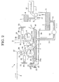
Referring to Figs. 1 and 2 showing a slasher 1 that carries out a
method of removing bubbles and floating matters from sizing solution in a
preferred embodiment according to the present invention, the slasher 1 has a
sizing tank 4 containing a size solution 3 to be applied to a warp 2 of warp
yarns, a sizing solution supply tank 5 for supplying the sizing solution of a
predetermined composition to the sizing tank 4, a sizing roller 6, a first
squeeze roller 7 and a second squeezing roller 8. The sizing solution 3 contained
in a reserve tank 9 is supplied through a supply pipe 10 when a solenoid
valve 11 placed in the supply pipe 10 is opened. The solenoid valve 11
is controlled for opening and closing by a controller 12. The controller 12
measures the level of the surface of the sizing solution 3 contained in the
sizing solution supply tank 5 by, for example, an ultrasonic level finder 13.
The controller 12 closes the solenoid valve 11 to stop supplying the sizing
solution to the sizing solution supply tank 5 upon the rise of the level of the
surface of the liquid solution 3 to an upper limit level, and opens the solenoid
valve 11 to start supplying the sizing solution to the sizing solution supply
tank 5 upon the fall of the level of the surface of the liquid solution 3 to a
lower limit level. The ultrasonic level finder 13 emits an ultrasonic signal
toward the surface of the sizing solution 3 contained in the sizing solution
supply tank 5, measures the time interval between the emission of the ultrasonic
signal and the return of its echo from the surface of the sizing solution
to determine the level of the surface of the sizing solution 3. The sizing solution
3 contained in the sizing solution supply tank 5 is supplied continuously
through a circulation pipe 14 having one end connected to the bottom
of the sizing tank 4 and the other end connected to the sizing solution supply
tank 5 by a circulation pump 15 placed in the circulation pipe 14.
The surface of the sizing solution 3 contained in the sizing tank 4 is
adjusted to a predetermined level by a fixed weir 16 having an upper edge 17
and disposed on the front end wall of the sizing tank 4. As shown in Fig. 1,
the sizing solution 3 overflows the fixed weir 16 and returns into the sizing
solution supply tank 5, so that the surface of the sizing solution 3 in the sizing
tank 4 is maintained at the predetermined level. The sizing tank 4 is
provided, in addition to the fixed weir 16, a movable weir 18 to carry out the
method of removing bubbles and floating matters according to the present
invention. The movable weir 18 includes a movable plate 19 contiguous
with the back end wall of the sizing tank 4, and a cylinder actuator 20 for
driving the movable plate 19 for movement toward and away from the back
end wall of the sizing tank 4. An upper end part of the movable plate 19 is
supported pivotally on a frame 21 by a pivot shaft 22. The cylinder actuator
20 has opposite ends pivotally connected to a lower end part of the movable
plate 19 and the frame 21 with two connecting pins 23, respectively. Normally,
the movable plate 19 is pressed against the back end wall of the sizing
tank 4. In this state, the upper edge of the movable plate 19 is at a level
higher than that of the upper edge 24 of the back end wall of the sizing tank
4. When necessary, the movable plate 19 is separated from the back end
wall of the sizing tank 4 by the cylinder actuator 20 as shown in Fig. 2 to
permit the sizing solution 3 to flow over the upper edge 24 of the back end
wall of the sizing tank 4 together with bubbles 25a and floating matters 25b,
such as films of the condensed sizing solution 3, floating on the surface of the
sizing solution 3 contained in the sizing tank 4. The bubbles 25a and the
floating matters 25b discharged from the sizing tank 4 return through a recovery
passage 26 into the sizing solution supply tank 5. The upper edge of
the movable plate 19 is at a level higher than that of the upper edge 17 of the
fixed weir 16, and the upper edge 24 of the back end wall of the sizing tank 4
is at a level lower than that of the upper edge 17 of the fixed weir 16.
The sizing roller 6 is partly immersed in the sizing solution 3 contained
in the sizing tank 4. The warp 2 guided by a guide roller 27 is
wound around the sizing roller 6 to immerse the warp 2 in the sizing solution
3 to that the warp 2 is soaked with the sizing solution 3. The first squeeze
roller 7 is disposed on the warp-receiving side of the sizing roller 6 to press
the warp 2 against the sizing roller 6. The second squeeze roller 8 is disposed
on the warp-delivering side of the sizing roller 6 to squeeze the warp 2
soaked with the sizing solution 3 so that the surplus sizing solution 3 is removed
from the warp 2 and the warp 2 is impregnated satisfactorily with the
sizing solution 3.
The sizing roller 6 has a shaft 28 supported by bearings 31 at a fixed
position on the frame 21. The sizing roller 6 is driven for rotation in the
direction of the arrow. The first squeeze roller 7 and the second squeeze
roller 8 have shafts 29 and 30 supported by levers 32 and 33, respectively.
The levers 32 and 33 are supported for swinging by shafts 34 and 35, respectively,
on the frame 21. A first cylinder actuator 38 has opposite ends pivotally
joined to the frame 21 and the lever 32 with pins 36, respectively. The
levers 32 and 33 are supported for swinging by shafts 34 and 35, respectively,
on the frame 21. A second cylinder actuator 39 has opposite ends pivotally
joined to the frame 21 and the lever 33 with pins 37, respectively. Pressures
to be applied to the sizing roller 6 by the first squeeze roller 7 and the second
squeeze roller 8 are adjustable by the cylinder actuators 38 and 39, respectively.
The first squeeze roller 7, similarly to the sizing roller 6, is immersed
partly in the sizing solution 3. The surfaces of the first squeeze roller 7 and
the second squeeze roller 7 are coated with rubber layers, respectively, to
apply pressure uniformly to the entire width of the warp 2 for squeezing so
that the warp 2 is sized uniformly.
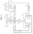
Fig. 3 shows circulating passages for circulating the sizing solution 3,
and a controller 12 for controlling the solenoid valve 11, and the movable
plate 19 of the movable weir 18. While the slasher 1 is in the steady-state
operation, the controller 12 measures the level of the surface of the sizing
solution 3 in the sizing solution supply tank 5 by the level finder 13. Upon
the detection of the fall of the surface of the sizing solution 3 to the lower
limit level by the level finder 13, the solenoid valve 11 is opened to replenish
the sizing solution supply tank 5 with the sizing solution 3 contained in the
reserve tank 9. Upon the rise of the surface of the sizing solution 3 in the
sizing solution supply tank 5 to the upper limit level, the level finder 13
sends a signal indicating the rise of the surface of the sizing solution 3 in the
sizing solution supply tank 5 to the upper limit level to the controller 12.
Then, the controller 12 closes the solenoid valve 11 to stop supplying the
sizing solution 3 from the reserve tank 9 to the sizing solution supply tank 5.
The pump 15 pumps the sizing solution 3 contained in the sizing solution
supply tank 5 into the sizing tank 4. While the movable plate 19 of the
movable weir 18 is held contiguously with the back end wall having the upper
edge 24, the sizing solution 3 overflows the fixed weir 16 having the upper
edge 17, and the overflowed sizing solution 3 returns to the sizing solution
supply tank 5. Thus, the surface of the sizing solution 3 in the sizing
solution supply tank 5 is maintained at the predetermined level corresponding
to the level of the upper edge 17.
While the slasher 1 is in the steady-state operation, at least the sizing
roller 6 is immersed partly in the sizing solution 3 and is rotated. The
warp 2 is sized by bringing the same into contact with the sizing roller 6
coated with the sizing solution 3 or by winding the same around the sizing
roller 6 and immersing the same in the sizing solution 3.
While the sizing solution 3 is stirred and scattered repeatedly by the
rotating sizing roller 6 partly immersed in the sizing solution 3, the first
squeeze roller 7 and the second squeeze roller 8 during a slashing process,
air is mixed in the sizing solution 3 to form the bubbles 25a, and the bubbles
25a floats on the surface of the sizing solution 3. Water evaporation from
the sizing solution 3 staying in the vicinity of the side and end walls of the
sizing tank 4 forms a film of the condensed sizing solution 3 over the surface
of the sizing solution 3. The film of the condensed sizing solution 3 is broken
into floating matters 25b of the condensed sizing solution 3 by the stirring
action of the sizing roller 6 and the first squeeze roller 7. The floating
matters 25b floats on the sizing solution 3. Although part of the bubbles
25a and the floating matters 25b overflows the fixed weir 16 of the sizing
tank 4 together with the sizing solution 3, the amount of the bubbles 25a and
the floating matters 25b increases gradually with time, the bubbles 25a and
the floating matters 25b gather in the vicinity of the fixed weir 16, and a
collection of the gathered bubbles 25a and the floating matters 25b extends
near to the sizing roller 6. The controller 12 operates the movable weir 18
at predetermined intervals while the slasher 1 is in steady-state operation.
Upon the reception of a level-lowering signal from a timer 40, the controller
12 drives the cylinder actuator 20 to separate the movable plate 19 from the
back end wall of the sizing tank 4 as shown in Fig. 2 to lower the surface of
the sizing solution 3 temporarily to a level corresponding to the upper edge
24 of the back end wall of the sizing tank 4 lower than the predetermined
level. Consequently, the sizing solution 3 flows toward the back end wall of
the sizing tank 4 and the bubbles 25a and the floating matters 25b spread
over the surface of the sizing solution 3. Then, the bubbles 25a and the
floating matters 25b floating in the vicinity of the fixed weir 16, in addition
to those floating in the vicinity of the movable weir 18 overflow movable weir
18 together with the sizing solution 3.
A large amount of the bubbles 25a and the floating matters 25b overflows
the lowered movable weir 18, i.e., the back end wall having the edge 24
of the sizing tank 4, together with the sizing solution 3 and is removed from
the sizing tank 4. Thus, the direct adhesion of the bubbles 25a and the
floating matters 25b formed by air mixed in the sizing solution 3 and fragments
of the film of the condensed sizing solution 3 formed due to the evaporation
of water from the sizing solution 3 to the warp 2, and application of
the bubbles 25a and the floating matters 25b to the warp 2 by the sizing
roller 6 can be prevented and the warp 2 can be stably and uniformly
slashed.
A predetermined time after the separation of the movable plate 19
from the sizing tank 4, the timer 40 gives a level-raising signal to the controller
12. Then, the controller 12 drives the cylinder actuator 20 to join the
movable plate 19 to the back end wall of the sizing tank 4 to raise the surface
of the sizing solution 3 to the level corresponding to that of the fixed weir 16,
and then the sizing solution 3 starts overflowing the fixed weir 16 and the
surface of the sizing solution 3 is maintained at the predetermined level.
Then, the sizing solution 3 flows toward the fixed weir 16 and the bubbles
25a and the floating matters 25b spread wide over the surface of the sizing
solution 3. The time of duration of the low level, the time of duration of
the high level, and the number of changing times by the hour are dependent
on the condition of the sizing solution 3, the rate of formation of the bubbles
25a and the floating matters 25b, and time necessary for removing the bubbles
25a and the floating matters 25b. For example, the time of duration of
the high level is determined so that the bubbles 25a and the floating matters
25b started gathering in the vicinity of the fixed weir 16 do not spread near
to the sizing roller 6 in this time. The time of duration of low level is determined
so that the surface of the sizing solution 3 is able to fall to a level corresponding
that of the upper edge 24 of the back end wall of the sizing tank 4
and the bubbles 25a and the floating matters 25b can be properly removed
from the sizing tank 4 in this time.
As mentioned above, the sizing tank 4 is provided with a plurality of
weirs and at least one of those weirs is the movable weir 18. While the
slasher 1 is in steady-state operation, the sizing solution 3 flows together
with the bubbles 25a and the floating matters 25b alternately toward the
fixed weir 16 and toward the movable weir 18, and the sizing solution 3 overflows
the sizing tank 4 together with the bubbles 25a and the floating matters
25b gathered in the vicinity of the weirs. Thus, the bubbles 25a and the
floating matters 25b are discharged over the nearby weir, namely, the fixed
weir 16 or the movable weir 18, and the flowing direction of the sizing solution
3 changes. Therefore, the bubbles 25a and the floating mattes 25b
spread wide over the surface of the sizing solution 3 in the sizing tank 4, and
are discharged together with a large amount of the sizing solution 3 from the
movable weir 18. Therefore, the bubbles 25a and the floating matters 25b
do not drift around the sizing roller 6 and the amount of the bubbles 25a and
the floating matters 25b that adhere to the warp 2 is less than that of those
that adhere to a warp on a conventional slasher.
Figs. 4 and 5 show another movable weir 18 including a movable
plate 19 having a lower part pivotally connected by a pin 22 to a bracket attached
to the outer surface of the back end wall of a sizing tank 4, and a
cylinder actuator 20 having opposite ends pivotally connected to a frame 21
and an upper part of the movable plate 19 by pins 23, respectively. The
level of the upper edge 24 of the weir 18, namely, the upper edge of the movable
plate 19, can be adjusted by adjusting the overall length of the cylinder
actuator 20. When the operating rod of the cylinder actuator 20 is projected
to set the movable weir 18 at a normal position for a steady-state operation
as shown in Fig. 4, the movable plate 19 is pressed against the back end wall
of the sizing tank 4, and the level of the upper edge 24 of the movable plate
19 is higher than that of the upper edge 17 of a fixed weir 16. When the
operating rod of the cylinder actuator 20 is retracted to set the movable weir
18 at a floating matter removing position for removing bubbles 25a and
floating matters 25b from the sizing tank 4 as shown in Fig. 5, the movable
plate 19 is separated from the back end wall of the sizing tank 4, and the
level of the upper edge 24 of the movable plate 19 is lower than that of the
upper edge 17 of the fixed weir 16, so that the bubbles 25a and the floating
matters 25b overflow the movable weir 18 together with the sizing solution 3.
Although the level of the surface of the sizing solution 3 lowers slightly and
the size pickup of the warp decreases slightly while the movable weir 18 is
set at the floating matter removing position, the level of the upper edge 24 of
the movable weir 18 is raised as high as possible to reduce the effect of the
fall of the surface of the sizing solution 3 on the size pickup.
The sizing tank 4 may be provided with only the movable weir 18.
When the sizing tank 4 is provided with only the movable weir 18, the level
of the upper edge 24 of the movable weir 18 (the movable plate 19) set at the
normal position corresponds to that of the edge 17 of the fixed edge 16 shown
in Figs. 1 to maintain the surface of the sizing solution 3 at the predetermined
level. When the movable weir 18 is set at the floating matter removing
position, the edge 24 of the movable plate 19 is set at a level lower
than the predetermined level of the surface of the sizing solution 3 to permit
the bubbles 25a and the floating matters 25b to overflow the movable weir
18.
Although the invention has been described in its preferred embodiments
with a certain degree of particularity, obviously many changes and
variations are possible therein. It is therefore to be understood that the
present invention may be practiced otherwise than as specifically described
herein without departing from the scope and spirit thereof.