EP1301654B1 - Method of producing graded platinum diffusion aluminide coating - Google Patents
Method of producing graded platinum diffusion aluminide coating Download PDFInfo
- Publication number
- EP1301654B1 EP1301654B1 EP01944587A EP01944587A EP1301654B1 EP 1301654 B1 EP1301654 B1 EP 1301654B1 EP 01944587 A EP01944587 A EP 01944587A EP 01944587 A EP01944587 A EP 01944587A EP 1301654 B1 EP1301654 B1 EP 1301654B1
- Authority
- EP
- European Patent Office
- Prior art keywords
- coating
- platinum
- aluminum
- substrate
- layer
- Prior art date
- Legal status (The legal status is an assumption and is not a legal conclusion. Google has not performed a legal analysis and makes no representation as to the accuracy of the status listed.)
- Expired - Lifetime
Links
- 238000000576 coating method Methods 0.000 title claims abstract description 137
- 239000011248 coating agent Substances 0.000 title claims abstract description 128
- BASFCYQUMIYNBI-UHFFFAOYSA-N platinum Chemical compound [Pt] BASFCYQUMIYNBI-UHFFFAOYSA-N 0.000 title claims abstract description 119
- 238000009792 diffusion process Methods 0.000 title claims abstract description 80
- 229910052697 platinum Inorganic materials 0.000 title claims abstract description 62
- 229910000951 Aluminide Inorganic materials 0.000 title claims abstract description 47
- 238000000034 method Methods 0.000 title claims abstract description 13
- 239000000654 additive Substances 0.000 claims abstract description 36
- 230000000996 additive effect Effects 0.000 claims abstract description 36
- 229910052782 aluminium Inorganic materials 0.000 claims abstract description 33
- XAGFODPZIPBFFR-UHFFFAOYSA-N aluminium Chemical compound [Al] XAGFODPZIPBFFR-UHFFFAOYSA-N 0.000 claims abstract description 31
- 239000000758 substrate Substances 0.000 claims abstract description 31
- 239000007787 solid Substances 0.000 claims abstract description 27
- 229910000601 superalloy Inorganic materials 0.000 claims abstract description 18
- 229910000838 Al alloy Inorganic materials 0.000 claims abstract description 12
- 238000005269 aluminizing Methods 0.000 claims abstract description 12
- 238000000151 deposition Methods 0.000 claims abstract description 4
- PXHVJJICTQNCMI-UHFFFAOYSA-N Nickel Chemical compound [Ni] PXHVJJICTQNCMI-UHFFFAOYSA-N 0.000 claims description 40
- 229910052759 nickel Inorganic materials 0.000 claims description 26
- 238000010438 heat treatment Methods 0.000 claims description 14
- 239000012190 activator Substances 0.000 claims description 7
- 150000004820 halides Chemical class 0.000 claims description 5
- 229910045601 alloy Inorganic materials 0.000 claims description 4
- 239000000956 alloy Substances 0.000 claims description 4
- 229910052751 metal Inorganic materials 0.000 claims 1
- 239000002184 metal Substances 0.000 claims 1
- 239000007789 gas Substances 0.000 description 37
- XKRFYHLGVUSROY-UHFFFAOYSA-N Argon Chemical compound [Ar] XKRFYHLGVUSROY-UHFFFAOYSA-N 0.000 description 32
- 229910052786 argon Inorganic materials 0.000 description 16
- 238000001816 cooling Methods 0.000 description 16
- 239000000203 mixture Substances 0.000 description 11
- 239000002245 particle Substances 0.000 description 11
- 230000000694 effects Effects 0.000 description 9
- NPXOKRUENSOPAO-UHFFFAOYSA-N Raney nickel Chemical compound [Al].[Ni] NPXOKRUENSOPAO-UHFFFAOYSA-N 0.000 description 7
- PNEYBMLMFCGWSK-UHFFFAOYSA-N aluminium oxide Inorganic materials [O-2].[O-2].[O-2].[Al+3].[Al+3] PNEYBMLMFCGWSK-UHFFFAOYSA-N 0.000 description 7
- 229910017052 cobalt Inorganic materials 0.000 description 7
- 239000010941 cobalt Substances 0.000 description 7
- GUTLYIVDDKVIGB-UHFFFAOYSA-N cobalt atom Chemical compound [Co] GUTLYIVDDKVIGB-UHFFFAOYSA-N 0.000 description 7
- KLZUFWVZNOTSEM-UHFFFAOYSA-K Aluminum fluoride Inorganic materials F[Al](F)F KLZUFWVZNOTSEM-UHFFFAOYSA-K 0.000 description 6
- 238000009713 electroplating Methods 0.000 description 6
- IRPGOXJVTQTAAN-UHFFFAOYSA-N 2,2,3,3,3-pentafluoropropanal Chemical compound FC(F)(F)C(F)(F)C=O IRPGOXJVTQTAAN-UHFFFAOYSA-N 0.000 description 5
- 229910052804 chromium Inorganic materials 0.000 description 5
- 230000003647 oxidation Effects 0.000 description 5
- 238000007254 oxidation reaction Methods 0.000 description 5
- 239000000843 powder Substances 0.000 description 5
- 239000012159 carrier gas Substances 0.000 description 4
- 238000005260 corrosion Methods 0.000 description 4
- 230000007797 corrosion Effects 0.000 description 4
- 229910000907 nickel aluminide Inorganic materials 0.000 description 4
- 239000000243 solution Substances 0.000 description 4
- 229910000943 NiAl Inorganic materials 0.000 description 3
- 238000005270 abrasive blasting Methods 0.000 description 3
- 239000012300 argon atmosphere Substances 0.000 description 3
- 229910002056 binary alloy Inorganic materials 0.000 description 3
- 238000005229 chemical vapour deposition Methods 0.000 description 3
- 239000013078 crystal Substances 0.000 description 3
- 238000007747 plating Methods 0.000 description 3
- 229910020639 Co-Al Inorganic materials 0.000 description 2
- 229910020675 Co—Al Inorganic materials 0.000 description 2
- 239000002253 acid Substances 0.000 description 2
- 239000011230 binding agent Substances 0.000 description 2
- TWNQGVIAIRXVLR-UHFFFAOYSA-N oxo(oxoalumanyloxy)alumane Chemical compound O=[Al]O[Al]=O TWNQGVIAIRXVLR-UHFFFAOYSA-N 0.000 description 2
- 230000002093 peripheral effect Effects 0.000 description 2
- 238000004881 precipitation hardening Methods 0.000 description 2
- XLYOFNOQVPJJNP-UHFFFAOYSA-N water Chemical compound O XLYOFNOQVPJJNP-UHFFFAOYSA-N 0.000 description 2
- 229910000995 CMSX-10 Inorganic materials 0.000 description 1
- 229910020630 Co Ni Inorganic materials 0.000 description 1
- 229910001347 Stellite Inorganic materials 0.000 description 1
- 238000005266 casting Methods 0.000 description 1
- AHICWQREWHDHHF-UHFFFAOYSA-N chromium;cobalt;iron;manganese;methane;molybdenum;nickel;silicon;tungsten Chemical compound C.[Si].[Cr].[Mn].[Fe].[Co].[Ni].[Mo].[W] AHICWQREWHDHHF-UHFFFAOYSA-N 0.000 description 1
- 238000004140 cleaning Methods 0.000 description 1
- 238000005336 cracking Methods 0.000 description 1
- 239000008367 deionised water Substances 0.000 description 1
- 229910021641 deionized water Inorganic materials 0.000 description 1
- 239000003792 electrolyte Substances 0.000 description 1
- 238000002149 energy-dispersive X-ray emission spectroscopy Methods 0.000 description 1
- 238000005516 engineering process Methods 0.000 description 1
- 238000005242 forging Methods 0.000 description 1
- 230000005484 gravity Effects 0.000 description 1
- 229910052735 hafnium Inorganic materials 0.000 description 1
- XLYOFNOQVPJJNP-UHFFFAOYSA-M hydroxide Chemical compound [OH-] XLYOFNOQVPJJNP-UHFFFAOYSA-M 0.000 description 1
- 238000007689 inspection Methods 0.000 description 1
- 238000005495 investment casting Methods 0.000 description 1
- 239000000463 material Substances 0.000 description 1
- 229910052750 molybdenum Inorganic materials 0.000 description 1
- 239000008055 phosphate buffer solution Substances 0.000 description 1
- -1 platinum modified nickel aluminide Chemical class 0.000 description 1
- 238000002360 preparation method Methods 0.000 description 1
- 230000001681 protective effect Effects 0.000 description 1
- 229910052702 rhenium Inorganic materials 0.000 description 1
- 239000006104 solid solution Substances 0.000 description 1
- 239000007921 spray Substances 0.000 description 1
- 238000004544 sputter deposition Methods 0.000 description 1
- 239000000126 substance Substances 0.000 description 1
- 229910052715 tantalum Inorganic materials 0.000 description 1
- 229910052721 tungsten Inorganic materials 0.000 description 1
- 238000005406 washing Methods 0.000 description 1
Images



Classifications
-
- C—CHEMISTRY; METALLURGY
- C23—COATING METALLIC MATERIAL; COATING MATERIAL WITH METALLIC MATERIAL; CHEMICAL SURFACE TREATMENT; DIFFUSION TREATMENT OF METALLIC MATERIAL; COATING BY VACUUM EVAPORATION, BY SPUTTERING, BY ION IMPLANTATION OR BY CHEMICAL VAPOUR DEPOSITION, IN GENERAL; INHIBITING CORROSION OF METALLIC MATERIAL OR INCRUSTATION IN GENERAL
- C23C—COATING METALLIC MATERIAL; COATING MATERIAL WITH METALLIC MATERIAL; SURFACE TREATMENT OF METALLIC MATERIAL BY DIFFUSION INTO THE SURFACE, BY CHEMICAL CONVERSION OR SUBSTITUTION; COATING BY VACUUM EVAPORATION, BY SPUTTERING, BY ION IMPLANTATION OR BY CHEMICAL VAPOUR DEPOSITION, IN GENERAL
- C23C10/00—Solid state diffusion of only metal elements or silicon into metallic material surfaces
- C23C10/02—Pretreatment of the material to be coated
-
- C—CHEMISTRY; METALLURGY
- C22—METALLURGY; FERROUS OR NON-FERROUS ALLOYS; TREATMENT OF ALLOYS OR NON-FERROUS METALS
- C22C—ALLOYS
- C22C19/00—Alloys based on nickel or cobalt
- C22C19/03—Alloys based on nickel or cobalt based on nickel
-
- C—CHEMISTRY; METALLURGY
- C22—METALLURGY; FERROUS OR NON-FERROUS ALLOYS; TREATMENT OF ALLOYS OR NON-FERROUS METALS
- C22C—ALLOYS
- C22C19/00—Alloys based on nickel or cobalt
- C22C19/03—Alloys based on nickel or cobalt based on nickel
- C22C19/05—Alloys based on nickel or cobalt based on nickel with chromium
- C22C19/051—Alloys based on nickel or cobalt based on nickel with chromium and Mo or W
- C22C19/057—Alloys based on nickel or cobalt based on nickel with chromium and Mo or W with the maximum Cr content being less 10%
-
- C—CHEMISTRY; METALLURGY
- C22—METALLURGY; FERROUS OR NON-FERROUS ALLOYS; TREATMENT OF ALLOYS OR NON-FERROUS METALS
- C22C—ALLOYS
- C22C19/00—Alloys based on nickel or cobalt
- C22C19/07—Alloys based on nickel or cobalt based on cobalt
-
- C—CHEMISTRY; METALLURGY
- C22—METALLURGY; FERROUS OR NON-FERROUS ALLOYS; TREATMENT OF ALLOYS OR NON-FERROUS METALS
- C22C—ALLOYS
- C22C21/00—Alloys based on aluminium
-
- C—CHEMISTRY; METALLURGY
- C22—METALLURGY; FERROUS OR NON-FERROUS ALLOYS; TREATMENT OF ALLOYS OR NON-FERROUS METALS
- C22C—ALLOYS
- C22C27/00—Alloys based on rhenium or a refractory metal not mentioned in groups C22C14/00 or C22C16/00
- C22C27/06—Alloys based on chromium
-
- C—CHEMISTRY; METALLURGY
- C23—COATING METALLIC MATERIAL; COATING MATERIAL WITH METALLIC MATERIAL; CHEMICAL SURFACE TREATMENT; DIFFUSION TREATMENT OF METALLIC MATERIAL; COATING BY VACUUM EVAPORATION, BY SPUTTERING, BY ION IMPLANTATION OR BY CHEMICAL VAPOUR DEPOSITION, IN GENERAL; INHIBITING CORROSION OF METALLIC MATERIAL OR INCRUSTATION IN GENERAL
- C23C—COATING METALLIC MATERIAL; COATING MATERIAL WITH METALLIC MATERIAL; SURFACE TREATMENT OF METALLIC MATERIAL BY DIFFUSION INTO THE SURFACE, BY CHEMICAL CONVERSION OR SUBSTITUTION; COATING BY VACUUM EVAPORATION, BY SPUTTERING, BY ION IMPLANTATION OR BY CHEMICAL VAPOUR DEPOSITION, IN GENERAL
- C23C10/00—Solid state diffusion of only metal elements or silicon into metallic material surfaces
- C23C10/06—Solid state diffusion of only metal elements or silicon into metallic material surfaces using gases
-
- C—CHEMISTRY; METALLURGY
- C23—COATING METALLIC MATERIAL; COATING MATERIAL WITH METALLIC MATERIAL; CHEMICAL SURFACE TREATMENT; DIFFUSION TREATMENT OF METALLIC MATERIAL; COATING BY VACUUM EVAPORATION, BY SPUTTERING, BY ION IMPLANTATION OR BY CHEMICAL VAPOUR DEPOSITION, IN GENERAL; INHIBITING CORROSION OF METALLIC MATERIAL OR INCRUSTATION IN GENERAL
- C23C—COATING METALLIC MATERIAL; COATING MATERIAL WITH METALLIC MATERIAL; SURFACE TREATMENT OF METALLIC MATERIAL BY DIFFUSION INTO THE SURFACE, BY CHEMICAL CONVERSION OR SUBSTITUTION; COATING BY VACUUM EVAPORATION, BY SPUTTERING, BY ION IMPLANTATION OR BY CHEMICAL VAPOUR DEPOSITION, IN GENERAL
- C23C28/00—Coating for obtaining at least two superposed coatings either by methods not provided for in a single one of groups C23C2/00 - C23C26/00 or by combinations of methods provided for in subclasses C23C and C25C or C25D
- C23C28/02—Coating for obtaining at least two superposed coatings either by methods not provided for in a single one of groups C23C2/00 - C23C26/00 or by combinations of methods provided for in subclasses C23C and C25C or C25D only coatings only including layers of metallic material
- C23C28/021—Coating for obtaining at least two superposed coatings either by methods not provided for in a single one of groups C23C2/00 - C23C26/00 or by combinations of methods provided for in subclasses C23C and C25C or C25D only coatings only including layers of metallic material including at least one metal alloy layer
-
- C—CHEMISTRY; METALLURGY
- C23—COATING METALLIC MATERIAL; COATING MATERIAL WITH METALLIC MATERIAL; CHEMICAL SURFACE TREATMENT; DIFFUSION TREATMENT OF METALLIC MATERIAL; COATING BY VACUUM EVAPORATION, BY SPUTTERING, BY ION IMPLANTATION OR BY CHEMICAL VAPOUR DEPOSITION, IN GENERAL; INHIBITING CORROSION OF METALLIC MATERIAL OR INCRUSTATION IN GENERAL
- C23C—COATING METALLIC MATERIAL; COATING MATERIAL WITH METALLIC MATERIAL; SURFACE TREATMENT OF METALLIC MATERIAL BY DIFFUSION INTO THE SURFACE, BY CHEMICAL CONVERSION OR SUBSTITUTION; COATING BY VACUUM EVAPORATION, BY SPUTTERING, BY ION IMPLANTATION OR BY CHEMICAL VAPOUR DEPOSITION, IN GENERAL
- C23C28/00—Coating for obtaining at least two superposed coatings either by methods not provided for in a single one of groups C23C2/00 - C23C26/00 or by combinations of methods provided for in subclasses C23C and C25C or C25D
- C23C28/02—Coating for obtaining at least two superposed coatings either by methods not provided for in a single one of groups C23C2/00 - C23C26/00 or by combinations of methods provided for in subclasses C23C and C25C or C25D only coatings only including layers of metallic material
- C23C28/023—Coating for obtaining at least two superposed coatings either by methods not provided for in a single one of groups C23C2/00 - C23C26/00 or by combinations of methods provided for in subclasses C23C and C25C or C25D only coatings only including layers of metallic material only coatings of metal elements only
-
- C—CHEMISTRY; METALLURGY
- C23—COATING METALLIC MATERIAL; COATING MATERIAL WITH METALLIC MATERIAL; CHEMICAL SURFACE TREATMENT; DIFFUSION TREATMENT OF METALLIC MATERIAL; COATING BY VACUUM EVAPORATION, BY SPUTTERING, BY ION IMPLANTATION OR BY CHEMICAL VAPOUR DEPOSITION, IN GENERAL; INHIBITING CORROSION OF METALLIC MATERIAL OR INCRUSTATION IN GENERAL
- C23C—COATING METALLIC MATERIAL; COATING MATERIAL WITH METALLIC MATERIAL; SURFACE TREATMENT OF METALLIC MATERIAL BY DIFFUSION INTO THE SURFACE, BY CHEMICAL CONVERSION OR SUBSTITUTION; COATING BY VACUUM EVAPORATION, BY SPUTTERING, BY ION IMPLANTATION OR BY CHEMICAL VAPOUR DEPOSITION, IN GENERAL
- C23C28/00—Coating for obtaining at least two superposed coatings either by methods not provided for in a single one of groups C23C2/00 - C23C26/00 or by combinations of methods provided for in subclasses C23C and C25C or C25D
- C23C28/02—Coating for obtaining at least two superposed coatings either by methods not provided for in a single one of groups C23C2/00 - C23C26/00 or by combinations of methods provided for in subclasses C23C and C25C or C25D only coatings only including layers of metallic material
- C23C28/028—Including graded layers in composition or in physical properties, e.g. density, porosity, grain size
-
- F—MECHANICAL ENGINEERING; LIGHTING; HEATING; WEAPONS; BLASTING
- F01—MACHINES OR ENGINES IN GENERAL; ENGINE PLANTS IN GENERAL; STEAM ENGINES
- F01D—NON-POSITIVE DISPLACEMENT MACHINES OR ENGINES, e.g. STEAM TURBINES
- F01D5/00—Blades; Blade-carrying members; Heating, heat-insulating, cooling or antivibration means on the blades or the members
- F01D5/12—Blades
- F01D5/28—Selecting particular materials; Particular measures relating thereto; Measures against erosion or corrosion
- F01D5/288—Protective coatings for blades
-
- F—MECHANICAL ENGINEERING; LIGHTING; HEATING; WEAPONS; BLASTING
- F05—INDEXING SCHEMES RELATING TO ENGINES OR PUMPS IN VARIOUS SUBCLASSES OF CLASSES F01-F04
- F05D—INDEXING SCHEME FOR ASPECTS RELATING TO NON-POSITIVE-DISPLACEMENT MACHINES OR ENGINES, GAS-TURBINES OR JET-PROPULSION PLANTS
- F05D2230/00—Manufacture
- F05D2230/90—Coating; Surface treatment
-
- F—MECHANICAL ENGINEERING; LIGHTING; HEATING; WEAPONS; BLASTING
- F05—INDEXING SCHEMES RELATING TO ENGINES OR PUMPS IN VARIOUS SUBCLASSES OF CLASSES F01-F04
- F05D—INDEXING SCHEME FOR ASPECTS RELATING TO NON-POSITIVE-DISPLACEMENT MACHINES OR ENGINES, GAS-TURBINES OR JET-PROPULSION PLANTS
- F05D2300/00—Materials; Properties thereof
- F05D2300/10—Metals, alloys or intermetallic compounds
- F05D2300/14—Noble metals, i.e. Ag, Au, platinum group metals
- F05D2300/143—Platinum group metals, i.e. Os, Ir, Pt, Ru, Rh, Pd
-
- F—MECHANICAL ENGINEERING; LIGHTING; HEATING; WEAPONS; BLASTING
- F05—INDEXING SCHEMES RELATING TO ENGINES OR PUMPS IN VARIOUS SUBCLASSES OF CLASSES F01-F04
- F05D—INDEXING SCHEME FOR ASPECTS RELATING TO NON-POSITIVE-DISPLACEMENT MACHINES OR ENGINES, GAS-TURBINES OR JET-PROPULSION PLANTS
- F05D2300/00—Materials; Properties thereof
- F05D2300/60—Properties or characteristics given to material by treatment or manufacturing
- F05D2300/611—Coating
-
- Y—GENERAL TAGGING OF NEW TECHNOLOGICAL DEVELOPMENTS; GENERAL TAGGING OF CROSS-SECTIONAL TECHNOLOGIES SPANNING OVER SEVERAL SECTIONS OF THE IPC; TECHNICAL SUBJECTS COVERED BY FORMER USPC CROSS-REFERENCE ART COLLECTIONS [XRACs] AND DIGESTS
- Y10—TECHNICAL SUBJECTS COVERED BY FORMER USPC
- Y10T—TECHNICAL SUBJECTS COVERED BY FORMER US CLASSIFICATION
- Y10T428/00—Stock material or miscellaneous articles
- Y10T428/12—All metal or with adjacent metals
- Y10T428/12458—All metal or with adjacent metals having composition, density, or hardness gradient
-
- Y—GENERAL TAGGING OF NEW TECHNOLOGICAL DEVELOPMENTS; GENERAL TAGGING OF CROSS-SECTIONAL TECHNOLOGIES SPANNING OVER SEVERAL SECTIONS OF THE IPC; TECHNICAL SUBJECTS COVERED BY FORMER USPC CROSS-REFERENCE ART COLLECTIONS [XRACs] AND DIGESTS
- Y10—TECHNICAL SUBJECTS COVERED BY FORMER USPC
- Y10T—TECHNICAL SUBJECTS COVERED BY FORMER US CLASSIFICATION
- Y10T428/00—Stock material or miscellaneous articles
- Y10T428/12—All metal or with adjacent metals
- Y10T428/12493—Composite; i.e., plural, adjacent, spatially distinct metal components [e.g., layers, joint, etc.]
- Y10T428/12736—Al-base component
-
- Y—GENERAL TAGGING OF NEW TECHNOLOGICAL DEVELOPMENTS; GENERAL TAGGING OF CROSS-SECTIONAL TECHNOLOGIES SPANNING OVER SEVERAL SECTIONS OF THE IPC; TECHNICAL SUBJECTS COVERED BY FORMER USPC CROSS-REFERENCE ART COLLECTIONS [XRACs] AND DIGESTS
- Y10—TECHNICAL SUBJECTS COVERED BY FORMER USPC
- Y10T—TECHNICAL SUBJECTS COVERED BY FORMER US CLASSIFICATION
- Y10T428/00—Stock material or miscellaneous articles
- Y10T428/12—All metal or with adjacent metals
- Y10T428/12493—Composite; i.e., plural, adjacent, spatially distinct metal components [e.g., layers, joint, etc.]
- Y10T428/12771—Transition metal-base component
- Y10T428/12861—Group VIII or IB metal-base component
- Y10T428/12875—Platinum group metal-base component
-
- Y—GENERAL TAGGING OF NEW TECHNOLOGICAL DEVELOPMENTS; GENERAL TAGGING OF CROSS-SECTIONAL TECHNOLOGIES SPANNING OVER SEVERAL SECTIONS OF THE IPC; TECHNICAL SUBJECTS COVERED BY FORMER USPC CROSS-REFERENCE ART COLLECTIONS [XRACs] AND DIGESTS
- Y10—TECHNICAL SUBJECTS COVERED BY FORMER USPC
- Y10T—TECHNICAL SUBJECTS COVERED BY FORMER US CLASSIFICATION
- Y10T428/00—Stock material or miscellaneous articles
- Y10T428/12—All metal or with adjacent metals
- Y10T428/12493—Composite; i.e., plural, adjacent, spatially distinct metal components [e.g., layers, joint, etc.]
- Y10T428/12771—Transition metal-base component
- Y10T428/12861—Group VIII or IB metal-base component
- Y10T428/12944—Ni-base component
Definitions
- the present invention relates to forming a platinum modified diffusion aluminide coating on a superalloy component, such as a gas turbine engine blade and vane, exposed to high service temperatures.
- Inwardly grown and outwardly grown platinum modified diffusion aluminide coatings have been formed on superalloy turbine engine components to meet these higher temperature requirements.
- One such inwardly grown platinum modified diffusion coating is formed by chemical vapor deposition using aluminide halide coating gas and comprises an inward diffusion zone and an outer two phase [PtAl 2 + (Ni, Pt) Al] layer.
- the two phase Pt modified diffusion aluminide coatings are relatively hard and brittle and have been observed to be sensitive to thermal mechanical fatigue (TMF) cracking in gas turbine engine service.
- One such outwardly grown platinum modified diffusion coating is formed by chemical vapor deposition using a low activity aluminide halide coating gas as described in US Patents 5 658 614 ; 5 716 720 ; 5 989 733 ; and 5 788 823 and comprises an inward diffusion zone and an outer (additive) single phase (Ni, Pt) Al layer.
- EP 0 897 966 discloses that high temperature oxidation resistance of an aluminide diffusion overcoated MCrALY coating system is substantially improved by chemical vapor deposition over aluminizing.
- An object of the present invention is to provide a gas phase aluminizing method using one or more solid sources of aluminum for forming on a substrate surface an outwardly grown, single phase diffusion aluminide coating that includes an outer additive layer having a graded Pt content from an outer toward an inner region thereof.
- the present invention also involves forming on a substrate, such as a nickel or cobalt base superalloy substrate, a platinum modified diffusion aluminide coating by depositing a layer comprising platinum on the substrate and then gas phase aluminizing the substrate in a coating chamber having a solid source of aluminum (e. g. aluminum alloy particulates) disposed therein close enough to the substrate surface as to form at an elevated coating temperature an outwardly grown diffusion aluminide coating having an inner diffusion zone and outer, single phase (Ni, Pt) Al additive layer having a concentration of platinum that is relatively higher at an outermost coating region than at an innermost coating region adjacent the diffusion zone.
- Gas phase aluminizing can be conducted with or without a prediffusion of the platinum layer into the substrate.
- the present invention also envisions forming on a substrate a platinum graded, single phase diffusion aluminide coating at a first surface area of the substrate and concurrently a different diffusion aluminide coating at a second surface area of the substrate in the same coating chamber.
- the present invention is advantageous to form on a nickel or cobalt base superalloy substrate an outwardly grown platinum modified diffusion aluminide coating having an outer, single phase (Ni, Pt) Al additive layer with a Pt content that is relatively higher at an outermost coating region than at an innermost coating region adjacent to a diffusion zone to impart oxidation and hot corrosion resistance thereto and improved ductility as compared to conventional two phase platinum modified diffusion coatings.
- an outwardly grown platinum modified diffusion aluminide coating having an outer, single phase (Ni, Pt) Al additive layer with a Pt content that is relatively higher at an outermost coating region than at an innermost coating region adjacent to a diffusion zone to impart oxidation and hot corrosion resistance thereto and improved ductility as compared to conventional two phase platinum modified diffusion coatings.
- the topmost layer of Fig. 5 is not part of the coating and is present only to make the metallographic sample.
- the invention involves forming on a nickel base superalloy, cobalt base superallloy, an outwardly grown diffusion aluminide coating characterized by having an inner diffusion zone and outer, additive single phase (Ni, Pt) Al layer having a concentration of platinum that is relatively higher at an outermost coating region than at an innermost coating region adjacent the diffusion zone.
- the single phase (Ni, Pt) Al layer comprises a platinum modified nickel aluminide where platinum is in solid solution in the aluminide.
- the substrate comprises a nickel or cobalt base superalloy which may comprise equiaxed, directionally solidified and single crystal castings as well as other forms of these materials, such as forgings, pressed powder components, machined components, and other forms.
- the substrate may comprise the PWA 1484 nickel base superalloy having a nominal composition of 10.0% Co, 8.7% Ta, 5.9% W, 5.65% Al, 5.0% Cr, 3.0% Re, 1.9% Mo, 0.10% Hf, and balance Ni (where % is in weight %) used for making single crystal turbine blades and vanes.
- nickel base superalloys which can be used include, but are not limited to, PWA 655, PWA 1422, PWA 1447, PWA 1455, PWA 1480, Rene N-5, Rene N-6, Rene 77, Rene 80, Rene 125, CSMX-4, and CMSX-10 nickel base superalloys.
- Cobalt based superalloys which can be used include, but are not limited to, Mar-M-509, Stellite 31, and WI 52 and other cobalt base superalloys.
- the turbine blade comprises the aforementioned PWA 1484 nickel base superalloy.
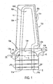
- the turbine blade is made as a single crystal investment casting having an airfoil region 10a with a leading edge 10b and trailing edge 10c.
- the airfoil includes a concave side 10d and convex side 10e.
- the turbine blade 10 includes a root region 10f and a platform region 10g between the root region and airfoil region.
- the root region can include a plurality of fir-tree ribs 10r.
- the platform region includes a pair of damper pockets or recesses 12 (one shown in Figure 1 ) with one damper pocket being located on the platform region at the concave side 10d and the other on the platform region at the convex side 10e of the airfoil region.
- Each damper pocket 12 is defined by an overhanging surface 12a of the platform region 10g and a side surface 12b thereof that has a surface extent defined by the dashed line L in Figure 1 . Damper pocket surface 12a extends generally perpendicular to damper pocket surface 12b.
- the platform region 10g also includes external first and second peripheral end surfaces 13a at the respective leading and trailing edges, first and second peripheral side surfaces 13b disposed at the concave and convex sides, upwardly facing surfaces 14 that face toward the airfoil region 10a, and outwardly facing surfaces 15 that face toward and away from the root region 10f.
- the turbine blade 10 includes an internal cooling passage 11 illustrated schematically having cooling air inlet openings 11a, 11b at the end E of the root region 10f.
- the internal cooling passage 11 extends from the inlet openings 11a, 11b through root region 10f and through the airfoil region 10a, the configuration of the passage 11 being simplified for convenience.
- the cooling passage 11 communicates to a plurality of exit openings 11e at the trailing edge 10c where cooling air is discharged.
- the exemplary turbine blade 10 described above is coated externally and internally with a protective outward diffusion aluminide coating in order to withstand oxidation and hot corrosion in service in the turbine section of the gas turbine engine.
- the damper pocket surfaces 12a, 12b are gas phase aluminized pursuant to the invention to form an outwardly grown, platinum graded single phase diffusion aluminide coating of the invention locally on surfaces 12a, 12b, while an outwardly grown, Pt-free nickel aluminide diffusion coating is formed on the external surfaces of airfoil region 10a and the surfaces 13a, 13b, 14 of platform region 10g.
- the root region 10f and surfaces 15 of the platform region 10g are uncoated.
- the surfaces of the internal cooling passage 11 are coated to form a Pt-free outward diffusion aluminide coating.
- the following steps are involved in coating the turbine blade 10 with the coatings described above.
- the investment cast turbine blades 10 are each subjected to multiple abrasive blasting operations where the damper pocket surfaces 12a, 12b are blasted with 240 mesh aluminum oxide grit at 68948 to 2757901 N/m 2 (10 to 40 psi) with a 76,2 to 177,8 mm (3 to 7 inch) grit blast nozzle standoff distance.
- each turbine blade 10 In preparation for electroplating of platinum on the damper pocket surfaces 12a, 12b, the external surfaces of each turbine blade 10, other than damper pocket surfaces 12a, 12b, are masked by a conventional peel type of maskant, while the internal cooling passage 11 is filled with wax.
- a useful electroplating solution comprised of a conventional aqueous phosphate buffer solution including hexachloroplatinic acid (Pt concentation of 1 to 12 grams per liter, pH of 6.5 to 7.5, specific gravity of 1.1285 to 1.1690 (16.5 to 21.0 Baume), electrolyte temperature of 71 to 77 °C (160 to 170 degrees F)) and a current density comprised 0.038 to 0.075 amperes/cm 2 (0.243-0.485 amperes/inch 2 ) to deposit a platinum layer.
- hexachloroplatinic acid Pt concentation of 1 to 12 grams per liter, pH of 6.5 to 7.5, specific gravity of 1.1285 to 1.1690 (16.5 to 21.0 Baume)
- electrolyte temperature 71 to 77 °C (160 to 170 degrees F)
- a current density comprised 0.038 to 0.075 amperes/cm 2 (0.243-0.485 amperes/inch 2
- a suitable platinum plating solution including hexachloroplatinic acid is described in US Patents 3 677 789 and 3 819 338 .
- a hydroxide based aqueous plating solution is described in US Patent 5 788 823 .
- the platinum layer can be deposited in an amount of 0.017 to 0.024 grams/cm 2 (0.109 to 0.153 grams/inch 2 ), typically 0.020 grams/cm 2 (0.131 grams/inch 2 ), on damper pocket surfaces 12a, 12b.
- These electroplating parameters are offered merely for purposes of illustration as other platinum electroplating solutions and parameters can be employed.
- the platinum layer also can be deposited on surfaces 12a, 12b by techniques other than electroplating, such as including, but not limited to sputtering and other deposition techniques.
- the maskant and the wax in internal passage 11 are removed from each turbine blade.
- the maskant and wax can be removed by heating the blades to 667 °C (1250 degrees F) in air.
- the blades then are high pressure spray washed internally in deionized water followed by washing in a washer available from Man-Gill Chemical Company, Magnus Division, which is operated at medium stroke for 15 to 30 minutes at 71 to 99 °C (160 to 210 degrees F) water temperature.
- the turbine blades then are dried for 30 minutes at 107 to 135 °C (225 to 275) degrees F.
- the turbine blades 10 can be subjected to an optional prediffusion heat treatment to diffuse the platinum layer into the superalloy substrate at the electroplated damper pocket surfaces 12a, 12b.
- the turbine blades can be heated in a flowing argon atmosphere in a retort to 1051 °C (1925 degrees F) for 5 to 10 minutes.
- the turbine blades are fan cooled from 1051 °C to 871 °C (1925 degrees F to 1600 degrees F) at 5.5 °C/minute (10 degrees F/minute) or faster to below 482 °C (900 degrees F)under argon atmosphere. The turbine blades then are removed from the retort.
- the airfoil region 10a and platform region 10g are then subjected to abrasive blasting using 240 mesh aluminum oxide grit at 275790 to 413685 N/m 2 (40 to 60 psi) with a 76.2 to 127 mm (3 to 5 inch) grit blast nozzle standoff distance.
- the root region 10f and damper pocket surfaces 12a, 12b are shielded and not grit blasted.
- the prediffusion heat treatment can be optional in practicing the invention such that the turbine blades with aselectroplated damper pocket surfaces 12a, 12b can be gas phase aluminized directly without the prediffusion heat treatment.
- the turbine blades 10 with or without the prediffusion heat treatment then are subjected to a gas phase aluminizing operation pursuant to the invention in a coating chamber, Figure 3 , disposed in a coating retort, Figure 4 .
- a pin fixture 20 comprising an hollow pins 20a and 20b on a base plate 20c is adhered to the end E of the root region 10f.
- the pins 20a, 20b extend into and communicate to the respective openings 11a, 11b of the internal passage 11 at the root end, Figure 2 .
- the maskant then is applied to root region 10f and surfaces 15 in Figure 1 .
- the maskant can comprise multiple layers of conventional M-1 maskant (stop-off comprising alumina in a binder) and M-7 maskant (sheath coat comprising mostly nickel powder in a binder), both maskants being available from Alloy Surfaces Co., Inc., Wilmington, Delaware.
- M-1 maskant stop-off comprising alumina in a binder
- M-7 maskant sheath coat comprising mostly nickel powder in a binder
- 2 coats of M-1 maskant and 4 coats of M-7 maskant can be applied to the above surfaces.
- These maskants are described only for purposes of illustration and not limitation as any other suitable maskant, such as a dry maskant, can be used.
- gas phase aluminizing of the turbine blades to form the coatings described above is conducted in a plurality of coating chambers 30, Figures 3 and 4 , carried on supports 40a on lifting post 40 positioned in coating retort 50.
- Each coating chamber 30 comprises a cylindrical, annular chamber 30a and a lid 301, the chamber and lid having a central passage 30p to receive lifting post 40 as illustrated in Figure 4 .
- Each coating chamber includes therein a lower chamber region 31a and upper coating chamber region 31b.
- a plurality of turbine blades 10 are held root-down in cofferdams 34 in upper chamber region 31b with the hollow pins 20a, 20b adhered on the root ends extending through respective pairs of holes in the bottom walls of the cofferdams 34 and wall W1 so as to communicate the hollow pins 20a, 20b to lower chamber 31a.
- each pin 20b and the corresponding holes in each cofferdam 34 and wall W1 are hidden behind pin 20a.
- the root regions 10f of a plurality of blades 10 are held in beds 37 of alumina (or other refractory) particulates in annular cofferdams 34, Figure 3 .
- each blade 10 Although only one blade 10 is shown so held in each cofferdam 34 for sake of convenience, the root regions 10f of a plurality of blades 10 typically are so held circumferentially spaced apart in each cofferdam 34.
- the root regions 10f are placed in each cofferdam 34 with the respective pins 20a, 20b communicated to the lower chamber region 31a and the alumina particulates of bed 37 then are introduced into the cofferdams 34 to embed the root regions 10f in the alumina particulates to an extent shown in Figure 3a .
- Inner and outer gas seals 30i, 30o are formed between the lower chamber region 31a and upper chamber region 31b by alumina grit filled and packed in the spaces between the annular chamber walls as illustrated in Figure 3 .
- the lower chamber region 31a includes a solid source S1 of aluminum (e. g. aluminum alloy particles) received in annular open wire basket B1 to generate at the elevated coating temperature to be employed (e. g. 1079 °C (1975 degrees F) plus or minus 13.8 °C (25 degrees F)) aluminum-bearing coating gas to form the diffusion aluminide coating on the interior surfaces of the cooling passage 11 of each turbine blade.
- a conventional halide activator (not shown), such as for example only AlF 3 , is used to initiate generation of the aluminum-bearing coating gas (e. g. AlF gas) from solid source S1 at the elevated coating temperature to be employed.
- An argon (or other carrier gas) ring-shaped inlet conduit 32 is positioned in the lower chamber region 31a to discharge argon carrier gas that carries the generated aluminumbearing coating gas through the pins 20a, 20b and the cooling passage 11 for discharge from the exit openings 11e at the trailing edge of the turbine blades.
- Each conduit 32 is connected to a conventional common source SA of argon (Ar) as shown in Figure 4 for the two topmost chambers 30 by individual piping 33 extending through the retort lid to a fitting (not shown) on each conduit 32.
- Each piping 33 is connected to a common pressure regulator R and a respective individual flowmeter FM outside the retort to control argon pressure and flow rate.
- argon source SA pressure regulator R, flowmeter FM, and piping 33 are shown only for the two topmost coating chambers 30 in the retort 50.
- Each conduit 32 of each of the other coating chambers 30 is connected in similar fashion to the common argon source SA and the common regulator R by its own piping (not shown).
- the aluminum activity in the solid source S1 (i. e. the activity of aluminum in the binary aluminum alloy particles S1) is controlled to form the desired type of diffusion aluminide coating on interior cooling passage surfaces at the elevated coating temperature.
- the aluminum activity in source S1 is controlled by selection of a particular aluminum alloy particle composition effective to form the desired type of coating at the particular coating temperature involved.
- the source S1 can comprise Co-Al binary alloy particulates with the particulates comprising, for example, 50 weight % Co and balance Al.
- the particulates can have a particle size of 4 mm by 16 mm (mm is millimeters).
- the activator can comprise AlF 3 powder sprinkled beneath each basket B1. During transport through the cooling passage 11 by the argon carrier gas, the aluminum-bearing coating gas will form the outward diffusion aluminide coating on the interior cooling passage surfaces.
- each coating chamber 30 to internally coat up to 36 turbine blades in each coating chamber 30 to form the above outward aluminide diffusion coating in internal passage 11, about 600 grams of AlF 3 powder activator can be sprinkled in each lower chamber region 31a beneath each basket B1 and 60-75 pounds of Co-Al alloy particulates placed in each basket B1 in each lower chamber region 31a.
- the outward diffusion aluminide coating so formed on internal passage walls has a microstructure comprising an inner diffusion zone and a single NiAl phase outer additive layer and has a total thickness in the range of 0.0127 to 0.0762 mm (0.0005 to 0.003 inch) for purposes of illustration.
- the upper chamber region 31b includes a plurality (three shown) of solid sources S2 of aluminum received in three respective annular open wire baskets B2 on horizontal chamber wall W1 with aluminum activity of sources S2 controlled by the binary alloy composition to form the desired diffusion aluminide coating on the exterior surfaces of the airfoil region 10a and on platform surfaces 13a, 13b and 14.
- a conventional halide activator (not shown), such as for example only, aluminum fluoride (AlF 3 ) powder, is sprinkled beneath the baskets B2 on wall W1 in an amount to initiate generation of aluminum-bearing coating gas (e. g. AlF gas) from solid sources S2 in upper chamber region 31b at the elevated coating temperature (e. g. 1079 °C (1975 degrees F) plus or minus 13.8 °C (25 degrees F)) to be employed.
- AlF gas aluminum-bearing coating gas
- the sources S2 can comprise a Cr-Al binary alloy particulates with the particles comprising for example, 70 weight % Cr and balance Al.
- the particulates can have a particle size of 4 mm by 16 mm.
- the activator can comprise AlF 3 powder.
- the outwardly grown, Pt-free nickel aluminide diffusion coating includes an inner diffusion zone proximate the substrate and an outer, Pt-free additive single phase NiAl layer and typically has a total thickness in the range of 0.0254 to 0.0762 mm (0.001 to 0.003 inch).
- the upper chamber region 31b also includes solid sources S3 of aluminum (e. g. binary aluminum alloy particles) disposed in the annular cofferdams 34.
- the solid sources S3 have a predetermined aluminum activity in the solid sources S3 and are in close enough proximity to the damper pocket surfaces 12a, 12b to form thereon a diffusion aluminide coating 100, Figure 5 , different from that formed on the surfaces of airfoil region 10a and platform surfaces 13a, 13b and 14 at the elevated coating temperature.
- the activity of aluminum in the sources S3 is controlled by selection of a particular binary aluminum alloy particle composition effective to form the desired type of coating at the particular coating temperature involved.
- the diffusion aluminide coating 100 formed only on damper pocket surfaces 12a, 12b includes an inner diffusion zone 100a and outer, additive Pt-bearing single phase (Ni, Pt) Al layer 100b, Figure 5 , having a concentration of platinum that is relatively higher at an outermost coating region (e. g. outer 20% of the additive layer thickness) than at an innermost coating region adjacent the diffusion zone 100a.
- This is in contrast to the above outwardly grown, Pt-free diffusion aluminide coating formed on the surfaces of airfoil region 10a and platform surfaces 13a, 13b and 14 to have an outer, additive single phase NiAl layer that is devoid of platinum.
- the coating 100 typically has a total thickness (layer 100a plus 100b) in the range of 0.0254 to 0.0762 mm (0.001 to 0.003 inch), typically 0.0508 mm (0.002 inch).
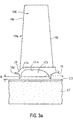
- the solid sources S3 can comprise the same aluminum alloy particulates as used in beds S2 (i. e. 70 weight % Cr and balance Al particles of 4 mm by 16 mm particle size) but positioned within a close enough distance D to the lowermost extent of damper pocket surface 12a delineated by the dashed line in Figure 1 to provide, at the elevated coating temperature, a higher aluminum species activity in the aluminum-bearing coating gas proximate the damper pocket surfaces 12a, 12b than is provided at the surfaces of the airfoil region 10a and upwardly facing surfaces of the platform region 10g by the solid sources S2 as a result of their being more remotely spaced from the airfoil surfaces and platform surfaces.
- each coating chamber 30 For purposes of illustration only, to coat 36 turbine blades in each coating chamber 30, 2.27 to 4.54 kg (5 to 10 pounds) of the Cr-Al alloy particulates (70 weight % Cr and balance Al) are placed in each cofferdam 34 with the upper surface of the source S3 positioned within a close enough distance D, Figure 3a , of from 9.52 to 12.70 mm (3/8 to 1/2 inch) to the lowermost extent of damper pocket surface 12a defined by the dashed line L to form the above graded platinum concentration (Pt gradient) through the thickness of the outer additive layer 100b.
- the sources S2 typically are spaced a distance of about 25.40 mm (1.00 inch) at their closest distance to the surfaces of the airfoil region 10a and platform surfaces 13a, 13b and 14.
- the solid sources S3 alternately can comprise aluminum alloy particulate having a different composition from that of solid sources S2.
- Gas phase aluminizing is effected by loading the coating chambers 30 having the turbine blades 10 and sources S1, S2, S3 therein on the supports 40a on lifting post 40 and placing the loaded post in the retort 50, Figure 4 , for heating to an elevated coating temperature (e. g. 1079 °C (1975 degrees F) plus or minus 13.8 °C (25 degrees F)) in a heating furnace (not shown).
- the elevated coating temperature can be selected as desired in dependence upon the compositions of solid aluminum sources S1, S2, S3, the composition of the substrates being coated and coating gas composition.
- the coating temperature of 1079 °C (1975 degrees F) plus or minus 13.8 °C (25 degrees F) is offered only for purposes of illustration with respect to coating the PWA 1484 nickel base superalloy turbine blades described above using the sources S1, S2, S3 and activators described above.
- the solid source S1 in the lower chamber region 31a generates aluminum-bearing coating gas (e. g. AIF gas) which is carried by the carrier gas (e. g. argon) supplied by piping 33 and conduits 32 for flow through the internal cooling passage 11 of each turbine blade to form the outward diffusion aluminide coating on the interior cooling passage surfaces.
- the spent coating gas is discharged from the exit openings Ile at the trailing edge of each turbine blade and flows out of a space SP between the coating chamber 30a and loose lid 301 thereon into the retort 50 from which it is exhausted through exhaust pipe 52.
- the aluminum-bearing coating gas generated from sources S2, S3 in the upper chamber region 31b forms the different diffusion aluminide coatings described above on the damper pocket surfaces 12a, 12b and the exterior surfaces of the airfoil region 10a and platform surfaces 13a, 13b and 14.
- the coating gases from sources S2, S3 are carried by the argon flow from gas discharge openings lie out of chamber 31b through space SP into the retort 50 from which it is exhausted via pipe 52.
- a coating chamber argon flow rate typically can be 2.662 m 3 /h (94 cf/h (cubic feet per hour)) plus or minus 0.170 m 3 /h (6 cf/h) at 206841 N/m 2 (30 psi) Ar plus or minus 17237 N/m 2 (2.5 psi).
- the retort argon flow is provided by the common argon source SA and the common pressure regulator R connected to piping 35 that extends through the retort lid behind the post 40 in Figure 4 to the bottom of the retort where the argon is discharged from the piping 35.
- Piping 35 is connected to a flowmeter FM1 downstream of the common regulator R to control argon pressure and flow rate.
- a retort argon flow rate typically can be 2.832 m 3 /h (100 cf/h) Ar plus or minus 0.170 m 3 /h (6 cf/h) at 86184 N/m 2 (12.5 psi) plus or minus 17237 N/m 2 (2.5 psi).
- the elevated coating temperature can be 1079 °C (1975 degrees F plus or minus 13.8 °C (25 degrees F) and coating time can be 5 hours plus or minus 15 minutes.
- the elevated coating temperature is controlled by adjustment of the heating furnace temperature in which the retort 50 is received.
- the heating furnace can comprise a conventional gas fired type of furnace or an electrical resistance heated furnace. After coating time has elapsed, the retort is removed from the heating furnace and fan cooled to below 204.4 °C (400 degrees F) while maintaining the argon atmosphere.
- the coated turbine blades then can be removed from the coating chambers 30, demasked to remove the M-1 and M-7 maskant layers, grit blasted with 240 mesh alumina at 103421 to 137895 N/m 2 (15-20 psi) with a 127 to 178 mm (5 to 7 inch) nozzle standoff distance, and washed as described above to clean the turbine blades.
- the coated turbine blades then can be subjected to a diffusion heat treatment (1079 °C (1975 degrees F) plus or minus 13.8 °C (25 degrees F) for 4 hours), precipitation hardening heat treatment (871 °C (1600 degrees F) plus or minus 13.8 °C (25 degrees F) for 8 hours followed by fan cool from 871 °C (1600 degrees F) to 648 °C (1200 degrees F) at 5.5 °C/minute (10 degrees F/minute) or faster to below 482°C (900 degrees F)), abrasive blasting using 240 mesh alumina grit at 103421 to 137895 N/m 2 (15 to 20 psi) with a 5 to 7 grit blast nozzle standoff distance, then conventionally heat tint inspected to evaluate surface coverage by the diffusion aluminide coating, which heat tint inspection forms no part of the present invention.
- a diffusion heat treatment (1079 °C (1975 degrees F) plus or minus 13.8 °C (25 degrees F) for 4 hours
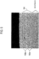
- Figure 5 illustrates a typical diffusion aluminide coating 100 formed on damper pocket surfaces 12a, 12b as including inner diffusion zone 100a and outer, additive single phase (Ni, Pt) Al layer 100b having a concentration of platinum that is relatively higher at an outermost coating region (e. g. outer 20% of the additive layer thickness) than at an innermost coating region adjacent the diffusion zone 100a.
- the outer additive (Ni, Pt) Al layer typically will have a Pt concentration of 25 to 45 weight % and up to 60 weight % in the outer 20% of the outer additive layer 100b and an Al concentration of 20 to 30 weight % and up to 35 weight % in the outer 20% of the outer additive layer 100b.
- the outer, additive (Ni, Pt) Al layer typically will have a Pt concentration of 10 to 25 weight % in the inner 20% of the outer additive layer 100b adjacent the diffusion zone 100a and an Al concentration of 20 to 25 weight % in the inner 20% of the outer additive layer 100b adjacent the diffusion zone 100a.
- the black regions in the additive layer 100b in Figure 5 are oxide and/or grit particles present at the original substrate surface.
- the Table below illustrates contents of elements at selected individual areas of the outer, additive single phase (Ni, Pt) Al layer 100b formed on damper pocket surfaces of PWA 1484 turbine blades.
- the compositions were measured at different depths (in microns) from the outermost surface of the outer additive layer 100b toward the diffusion zone by energy dispersive X-ray spectroscopy. The samples were measured before the diffusion and precipitation hardening heat treatments.
- the area designations 12, 13 indicate samples coated in the inner basket of Figure 3 .
- Microns ( ⁇ m) is the depth from the outermost surface of the additive layer 100b.
- the Table reveals a distinct Pt gradient in the outer, additive layer 100b from the outermost surface thereof toward the diffusion zone 100a in the as-aluminized condition. Gradients of Al, Cr, Co and Ni are also evident.
- the present invention is advantageous to provide an outwardly grown platinum modified diffusion aluminide coating having a single phase additive outer layer with a Pt content that is relatively higher at an outermost coating region than at an innermost coating region adjacent a diffusion zone to impart oxidation and hot corrosion resistance thereto and improved ductility as compared to conventional two phase platinum modified diffusion coatings.
- Such outwardly grown, graded platinum modified diffusion aluminide coating can be formed at other regions of turbine blades and vanes (referred to as airfoils).
- airfoils regions of turbine blades and vanes
- some or all of the exterior surfaces of the airfoil region 10a and/or platform region 10g can be coated pursuant to the invention to form the outwardly grown, graded platinum modified diffusion aluminide coating, Figure 5 , thereon.
- the airfoil region would be platinum electroplated as described above and the distance of the airfoil region to the aluminum sources S2 would be reduced to form the outwardly grown, graded platinum modified diffusion aluminide coating of Figure 5 thereon.
Landscapes
- Chemical & Material Sciences (AREA)
- Engineering & Computer Science (AREA)
- Materials Engineering (AREA)
- Mechanical Engineering (AREA)
- Metallurgy (AREA)
- Organic Chemistry (AREA)
- Chemical Kinetics & Catalysis (AREA)
- General Engineering & Computer Science (AREA)
- Turbine Rotor Nozzle Sealing (AREA)
- Solid-Phase Diffusion Into Metallic Material Surfaces (AREA)
- Other Surface Treatments For Metallic Materials (AREA)
Abstract
Description
- The present invention relates to forming a platinum modified diffusion aluminide coating on a superalloy component, such as a gas turbine engine blade and vane, exposed to high service temperatures.
- Advancements in propulsion technologies have required gas turbine engines to operate at higher temperatures. This increase in operating temperature has required concomitant advancements in the operating temperatures of metallic (e. g. nickel and cobalt base superalloy) turbine engine components to withstand oxidation and hot corrosion in service. Inwardly grown and outwardly grown platinum modified diffusion aluminide coatings have been formed on superalloy turbine engine components to meet these higher temperature requirements. One such inwardly grown platinum modified diffusion coating is formed by chemical vapor deposition using aluminide halide coating gas and comprises an inward diffusion zone and an outer two phase [PtAl2 + (Ni, Pt) Al] layer. The two phase Pt modified diffusion aluminide coatings are relatively hard and brittle and have been observed to be sensitive to thermal mechanical fatigue (TMF) cracking in gas turbine engine service.
- One such outwardly grown platinum modified diffusion coating is formed by chemical vapor deposition using a low activity aluminide halide coating gas as described in
US Patents 5 658 614 ;5 716 720 ;5 989 733 ; and5 788 823 and comprises an inward diffusion zone and an outer (additive) single phase (Ni, Pt) Al layer. Furthermore,EP 0 897 966 discloses that high temperature oxidation resistance of an aluminide diffusion overcoated MCrALY coating system is substantially improved by chemical vapor deposition over aluminizing. - An object of the present invention is to provide a gas phase aluminizing method using one or more solid sources of aluminum for forming on a substrate surface an outwardly grown, single phase diffusion aluminide coating that includes an outer additive layer having a graded Pt content from an outer toward an inner region thereof.
- The present invention also involves forming on a substrate, such as a nickel or cobalt base superalloy substrate, a platinum modified diffusion aluminide coating by depositing a layer comprising platinum on the substrate and then gas phase aluminizing the substrate in a coating chamber having a solid source of aluminum (e. g. aluminum alloy particulates) disposed therein close enough to the substrate surface as to form at an elevated coating temperature an outwardly grown diffusion aluminide coating having an inner diffusion zone and outer, single phase (Ni, Pt) Al additive layer having a concentration of platinum that is relatively higher at an outermost coating region than at an innermost coating region adjacent the diffusion zone. Gas phase aluminizing can be conducted with or without a prediffusion of the platinum layer into the substrate.
- The present invention also envisions forming on a substrate a platinum graded, single phase diffusion aluminide coating at a first surface area of the substrate and concurrently a different diffusion aluminide coating at a second surface area of the substrate in the same coating chamber.
- The present invention is advantageous to form on a nickel or cobalt base superalloy substrate an outwardly grown platinum modified diffusion aluminide coating having an outer, single phase (Ni, Pt) Al additive layer with a Pt content that is relatively higher at an outermost coating region than at an innermost coating region adjacent to a diffusion zone to impart oxidation and hot corrosion resistance thereto and improved ductility as compared to conventional two phase platinum modified diffusion coatings.
- The above objects and advantages of the present invention will become more readily apparent from the following description taken with the following drawings.
-
-
Figure 1 is an elevational view of a gas turbine engine blade having an airfoil region, a root region and a platform region with a damper pocket or recess beneath the platform region and located on the concave side and convex side of the airfoil. -
Figure 2 is an elevational view of a pin fixture to be positioned in the root end of a turbine blade for conducting coating gas through internal cooling passages of the turbine blade. -
Figure 3 is a partial schematic view of a coating chamber in which the turbine blades are coated. The coating chamber comprises a cylindrical annular chamber with a lid and having a central passage to receive a lifting post as illustrated inFigure 4 . -
Figure 3a is partial enlarged elevational view of the turbine blade with the damper pocket proximate a source of aluminum. -
Figure 4 is a schematic sectional view of the retort showing a plurality of coating chambers positioned therein on a lifting post. -
Figure 5 is a photomicrograph at 475X of an outwardly grown diffusion aluminide coating having an inner diffusion zone and outer single phase additive layer having a concentration of platinum that is relatively higher at an outermost coating region than at an innermost coating region adjacent the diffusion zone. - The topmost layer of
Fig. 5 is not part of the coating and is present only to make the metallographic sample. - The invention involves forming on a nickel base superalloy, cobalt base superallloy, an outwardly grown diffusion aluminide coating characterized by having an inner diffusion zone and outer, additive single phase (Ni, Pt) Al layer having a concentration of platinum that is relatively higher at an outermost coating region than at an innermost coating region adjacent the diffusion zone. The single phase (Ni, Pt) Al layer comprises a platinum modified nickel aluminide where platinum is in solid solution in the aluminide.
- The substrate comprises a nickel or cobalt base superalloy which may comprise equiaxed, directionally solidified and single crystal castings as well as other forms of these materials, such as forgings, pressed powder components, machined components, and other forms. For example only, the substrate may comprise the PWA 1484 nickel base superalloy having a nominal composition of 10.0% Co, 8.7% Ta, 5.9% W, 5.65% Al, 5.0% Cr, 3.0% Re, 1.9% Mo, 0.10% Hf, and balance Ni (where % is in weight %) used for making single crystal turbine blades and vanes. Other nickel base superalloys which can be used include, but are not limited to, PWA 655, PWA 1422, PWA 1447, PWA 1455, PWA 1480, Rene N-5, Rene N-6, Rene 77, Rene 80, Rene 125, CSMX-4, and CMSX-10 nickel base superalloys. Cobalt based superalloys which can be used include, but are not limited to, Mar-M-509, Stellite 31, and WI 52 and other cobalt base superalloys.
- For purposes of illustration and not limitation, the invention will be described herebelow with respect to forming the outwardly grown, graded platinum modified diffusion aluminide coating on a selected region of a
gas turbine blade 10 as illustrated inFigure 1 . The turbine blade comprises the aforementioned PWA 1484 nickel base superalloy. The turbine blade is made as a single crystal investment casting having anairfoil region 10a with a leadingedge 10b andtrailing edge 10c. The airfoil includes aconcave side 10d andconvex side 10e. Theturbine blade 10 includes aroot region 10f and aplatform region 10g between the root region and airfoil region. The root region can include a plurality of fir-tree ribs 10r. The platform region includes a pair of damper pockets or recesses 12 (one shown inFigure 1 ) with one damper pocket being located on the platform region at theconcave side 10d and the other on the platform region at theconvex side 10e of the airfoil region. Eachdamper pocket 12 is defined by anoverhanging surface 12a of theplatform region 10g and aside surface 12b thereof that has a surface extent defined by the dashed line L inFigure 1 .Damper pocket surface 12a extends generally perpendicular todamper pocket surface 12b. - The
platform region 10g also includes external first and secondperipheral end surfaces 13a at the respective leading and trailing edges, first and secondperipheral side surfaces 13b disposed at the concave and convex sides, upwardly facingsurfaces 14 that face toward theairfoil region 10a, and outwardly facingsurfaces 15 that face toward and away from theroot region 10f. - The
turbine blade 10 includes aninternal cooling passage 11 illustrated schematically having coolingair inlet openings root region 10f. Theinternal cooling passage 11 extends from theinlet openings root region 10f and through theairfoil region 10a, the configuration of thepassage 11 being simplified for convenience. In the airfoil region, thecooling passage 11 communicates to a plurality of exit openings 11e at thetrailing edge 10c where cooling air is discharged. - The
exemplary turbine blade 10 described above is coated externally and internally with a protective outward diffusion aluminide coating in order to withstand oxidation and hot corrosion in service in the turbine section of the gas turbine engine. - In a particular embodiment offered for purposes of illustration and not limitation, the
damper pocket surfaces surfaces airfoil region 10a and thesurfaces platform region 10g. Theroot region 10f andsurfaces 15 of theplatform region 10g are uncoated. The surfaces of theinternal cooling passage 11 are coated to form a Pt-free outward diffusion aluminide coating. - For purposes of illustration and not limitation, the following steps are involved in coating the
turbine blade 10 with the coatings described above. In particular, the investmentcast turbine blades 10 are each subjected to multiple abrasive blasting operations where thedamper pocket surfaces - In preparation for electroplating of platinum on the
damper pocket surfaces turbine blade 10, other thandamper pocket surfaces internal cooling passage 11 is filled with wax. - Each masked turbine blade then is subjected to an electroplating operation to deposit a platinum layer on the
damper pocket surfaces US Patents 3 677 789 and3 819 338 . A hydroxide based aqueous plating solution is described inUS Patent 5 788 823 . The platinum layer can be deposited in an amount of 0.017 to 0.024 grams/cm2 (0.109 to 0.153 grams/inch2), typically 0.020 grams/cm2 (0.131 grams/inch2), ondamper pocket surfaces surfaces - After plating, the maskant and the wax in
internal passage 11 are removed from each turbine blade. The maskant and wax can be removed by heating the blades to 667 °C (1250 degrees F) in air. The blades then are high pressure spray washed internally in deionized water followed by washing in a washer available from Man-Gill Chemical Company, Magnus Division, which is operated at medium stroke for 15 to 30 minutes at 71 to 99 °C (160 to 210 degrees F) water temperature. The turbine blades then are dried for 30 minutes at 107 to 135 °C (225 to 275) degrees F. - After cleaning as described above, the
turbine blades 10 can be subjected to an optional prediffusion heat treatment to diffuse the platinum layer into the superalloy substrate at the electroplateddamper pocket surfaces airfoil region 10a andplatform region 10g are then subjected to abrasive blasting using 240 mesh aluminum oxide grit at 275790 to 413685 N/m2 (40 to 60 psi) with a 76.2 to 127 mm (3 to 5 inch) grit blast nozzle standoff distance. Theroot region 10f anddamper pocket surfaces damper pocket surfaces - The
turbine blades 10 with or without the prediffusion heat treatment then are subjected to a gas phase aluminizing operation pursuant to the invention in a coating chamber,Figure 3 , disposed in a coating retort,Figure 4 . - Prior to gas phase aluminizing, a
pin fixture 20 comprising anhollow pins root region 10f. Thepins respective openings internal passage 11 at the root end,Figure 2 . - Maskant then is applied to root
region 10f and surfaces 15 inFigure 1 . The maskant can comprise multiple layers of conventional M-1 maskant (stop-off comprising alumina in a binder) and M-7 maskant (sheath coat comprising mostly nickel powder in a binder), both maskants being available from Alloy Surfaces Co., Inc., Wilmington, Delaware. For example, 2 coats of M-1 maskant and 4 coats of M-7 maskant can be applied to the above surfaces. These maskants are described only for purposes of illustration and not limitation as any other suitable maskant, such as a dry maskant, can be used. - For purposes of illustration and not limitation, gas phase aluminizing of the turbine blades to form the coatings described above is conducted in a plurality of
coating chambers 30,Figures 3 and4 , carried onsupports 40a on liftingpost 40 positioned incoating retort 50. Eachcoating chamber 30 comprises a cylindrical,annular chamber 30a and alid 301, the chamber and lid having acentral passage 30p to receive liftingpost 40 as illustrated inFigure 4 . - Each coating chamber includes therein a
lower chamber region 31a and uppercoating chamber region 31b. A plurality ofturbine blades 10 are held root-down incofferdams 34 inupper chamber region 31b with thehollow pins cofferdams 34 and wall W1 so as to communicate thehollow pins lower chamber 31a. InFigure 3 , eachpin 20b and the corresponding holes in eachcofferdam 34 and wall W1 are hidden behindpin 20a. Theroot regions 10f of a plurality ofblades 10 are held inbeds 37 of alumina (or other refractory) particulates inannular cofferdams 34,Figure 3 . Although only oneblade 10 is shown so held in eachcofferdam 34 for sake of convenience, theroot regions 10f of a plurality ofblades 10 typically are so held circumferentially spaced apart in eachcofferdam 34. Theroot regions 10f are placed in eachcofferdam 34 with therespective pins lower chamber region 31a and the alumina particulates ofbed 37 then are introduced into thecofferdams 34 to embed theroot regions 10f in the alumina particulates to an extent shown inFigure 3a . Inner and outer gas seals 30i, 30o are formed between thelower chamber region 31a andupper chamber region 31b by alumina grit filled and packed in the spaces between the annular chamber walls as illustrated inFigure 3 . - The
lower chamber region 31a includes a solid source S1 of aluminum (e. g. aluminum alloy particles) received in annular open wire basket B1 to generate at the elevated coating temperature to be employed (e. g. 1079 °C (1975 degrees F) plus or minus 13.8 °C (25 degrees F)) aluminum-bearing coating gas to form the diffusion aluminide coating on the interior surfaces of thecooling passage 11 of each turbine blade. An amount of a conventional halide activator (not shown), such as for example only AlF3, is used to initiate generation of the aluminum-bearing coating gas (e. g. AlF gas) from solid source S1 at the elevated coating temperature to be employed. An argon (or other carrier gas) ring-shapedinlet conduit 32 is positioned in thelower chamber region 31a to discharge argon carrier gas that carries the generated aluminumbearing coating gas through thepins cooling passage 11 for discharge from the exit openings 11e at the trailing edge of the turbine blades. Eachconduit 32 is connected to a conventional common source SA of argon (Ar) as shown inFigure 4 for the twotopmost chambers 30 by individual piping 33 extending through the retort lid to a fitting (not shown) on eachconduit 32. Each piping 33 is connected to a common pressure regulator R and a respective individual flowmeter FM outside the retort to control argon pressure and flow rate. For sake of convenience, the argon source SA, pressure regulator R, flowmeter FM, and piping 33 are shown only for the twotopmost coating chambers 30 in theretort 50. Eachconduit 32 of each of theother coating chambers 30 is connected in similar fashion to the common argon source SA and the common regulator R by its own piping (not shown). - The aluminum activity in the solid source S1 (i. e. the activity of aluminum in the binary aluminum alloy particles S1) is controlled to form the desired type of diffusion aluminide coating on interior cooling passage surfaces at the elevated coating temperature. The aluminum activity in source S1 is controlled by selection of a particular aluminum alloy particle composition effective to form the desired type of coating at the particular coating temperature involved. For purposes of illustration and not limitation, to form the above described outward type of diffusion aluminide coating on the interior cooling passage surfaces, the source S1 can comprise Co-Al binary alloy particulates with the particulates comprising, for example, 50 weight % Co and balance Al. The particulates can have a particle size of 4 mm by 16 mm (mm is millimeters). The activator can comprise AlF3 powder sprinkled beneath each basket B1. During transport through the
cooling passage 11 by the argon carrier gas, the aluminum-bearing coating gas will form the outward diffusion aluminide coating on the interior cooling passage surfaces. - For purposes of illustration and not limitation, to internally coat up to 36 turbine blades in each
coating chamber 30 to form the above outward aluminide diffusion coating ininternal passage 11, about 600 grams of AlF3 powder activator can be sprinkled in eachlower chamber region 31a beneath each basket B1 and 60-75 pounds of Co-Al alloy particulates placed in each basket B1 in eachlower chamber region 31a. The outward diffusion aluminide coating so formed on internal passage walls has a microstructure comprising an inner diffusion zone and a single NiAl phase outer additive layer and has a total thickness in the range of 0.0127 to 0.0762 mm (0.0005 to 0.003 inch) for purposes of illustration. - The
upper chamber region 31b includes a plurality (three shown) of solid sources S2 of aluminum received in three respective annular open wire baskets B2 on horizontal chamber wall W1 with aluminum activity of sources S2 controlled by the binary alloy composition to form the desired diffusion aluminide coating on the exterior surfaces of theairfoil region 10a and onplatform surfaces upper chamber region 31b at the elevated coating temperature (e. g. 1079 °C (1975 degrees F) plus or minus 13.8 °C (25 degrees F)) to be employed. - For purposes of illustration and not limitation, to form the above outwardly grown, Pt-free nickel aluminide diffusion coating on the exterior surfaces of the
airfoil region 10a andplatform surfaces upper chamber region 31b. The outwardly grown, Pt-free nickel aluminide diffusion coating includes an inner diffusion zone proximate the substrate and an outer, Pt-free additive single phase NiAl layer and typically has a total thickness in the range of 0.0254 to 0.0762 mm (0.001 to 0.003 inch). - Pursuant to an embodiment of the invention, the
upper chamber region 31b also includes solid sources S3 of aluminum (e. g. binary aluminum alloy particles) disposed in theannular cofferdams 34. The solid sources S3 have a predetermined aluminum activity in the solid sources S3 and are in close enough proximity to thedamper pocket surfaces diffusion aluminide coating 100,Figure 5 , different from that formed on the surfaces ofairfoil region 10a andplatform surfaces - In particular, the
diffusion aluminide coating 100 formed only ondamper pocket surfaces inner diffusion zone 100a and outer, additive Pt-bearing single phase (Ni, Pt)Al layer 100b,Figure 5 , having a concentration of platinum that is relatively higher at an outermost coating region (e. g. outer 20% of the additive layer thickness) than at an innermost coating region adjacent thediffusion zone 100a. This is in contrast to the above outwardly grown, Pt-free diffusion aluminide coating formed on the surfaces ofairfoil region 10a andplatform surfaces coating 100 typically has a total thickness (layer 100a plus 100b) in the range of 0.0254 to 0.0762 mm (0.001 to 0.003 inch), typically 0.0508 mm (0.002 inch). - For purposes of illustration and not limitation, the solid sources S3 can comprise the same aluminum alloy particulates as used in beds S2 (i. e. 70 weight % Cr and balance Al particles of 4 mm by 16 mm particle size) but positioned within a close enough distance D to the lowermost extent of
damper pocket surface 12a delineated by the dashed line inFigure 1 to provide, at the elevated coating temperature, a higher aluminum species activity in the aluminum-bearing coating gas proximate thedamper pocket surfaces airfoil region 10a and upwardly facing surfaces of theplatform region 10g by the solid sources S2 as a result of their being more remotely spaced from the airfoil surfaces and platform surfaces. - For purposes of illustration only, to coat 36 turbine blades in each
coating chamber 30, 2.27 to 4.54 kg (5 to 10 pounds) of the Cr-Al alloy particulates (70 weight % Cr and balance Al) are placed in eachcofferdam 34 with the upper surface of the source S3 positioned within a close enough distance D,Figure 3a , of from 9.52 to 12.70 mm (3/8 to 1/2 inch) to the lowermost extent ofdamper pocket surface 12a defined by the dashed line L to form the above graded platinum concentration (Pt gradient) through the thickness of theouter additive layer 100b. On the other hand, the sources S2 typically are spaced a distance of about 25.40 mm (1.00 inch) at their closest distance to the surfaces of theairfoil region 10a andplatform surfaces - The solid sources S3 alternately can comprise aluminum alloy particulate having a different composition from that of solid sources S2. The composition (i. e. activity) of the solid sources
- S3 and their distance from the
damper pocket surfaces outer additive layer 100b. - Gas phase aluminizing is effected by loading the
coating chambers 30 having theturbine blades 10 and sources S1, S2, S3 therein on thesupports 40a on liftingpost 40 and placing the loaded post in theretort 50,Figure 4 , for heating to an elevated coating temperature (e. g. 1079 °C (1975 degrees F) plus or minus 13.8 °C (25 degrees F)) in a heating furnace (not shown). The elevated coating temperature can be selected as desired in dependence upon the compositions of solid aluminum sources S1, S2, S3, the composition of the substrates being coated and coating gas composition. The coating temperature of 1079 °C (1975 degrees F) plus or minus 13.8 °C (25 degrees F) is offered only for purposes of illustration with respect to coating the PWA 1484 nickel base superalloy turbine blades described above using the sources S1, S2, S3 and activators described above. - During gas phase aluminizing in the
coating chambers 30 in theretort 50, the solid source S1 in thelower chamber region 31a generates aluminum-bearing coating gas (e. g. AIF gas) which is carried by the carrier gas (e. g. argon) supplied by piping 33 andconduits 32 for flow through theinternal cooling passage 11 of each turbine blade to form the outward diffusion aluminide coating on the interior cooling passage surfaces. The spent coating gas is discharged from the exit openings Ile at the trailing edge of each turbine blade and flows out of a space SP between thecoating chamber 30a andloose lid 301 thereon into theretort 50 from which it is exhausted throughexhaust pipe 52. - The aluminum-bearing coating gas generated from sources S2, S3 in the
upper chamber region 31b forms the different diffusion aluminide coatings described above on thedamper pocket surfaces airfoil region 10a andplatform surfaces chamber 31b through space SP into theretort 50 from which it is exhausted viapipe 52. - For forming the different internal and external aluminide diffusion coatings described in detail above on the PWA 1484
alloy turbine blades 10, thecoating chambers 30 andretort 50 initially are purged of air using argon flow. During gas phase aluminizing, a coating chamber argon flow rate typically can be 2.662 m3/h (94 cf/h (cubic feet per hour)) plus or minus 0.170 m3/h (6 cf/h) at 206841 N/m2 (30 psi) Ar plus or minus 17237 N/m2 (2.5 psi). The retort argon flow is provided by the common argon source SA and the common pressure regulator R connected to piping 35 that extends through the retort lid behind thepost 40 inFigure 4 to the bottom of the retort where the argon is discharged from thepiping 35.Piping 35 is connected to a flowmeter FM1 downstream of the common regulator R to control argon pressure and flow rate. A retort argon flow rate typically can be 2.832 m3/h (100 cf/h) Ar plus or minus 0.170 m3/h (6 cf/h) at 86184 N/m2 (12.5 psi) plus or minus 17237 N/m2 (2.5 psi). - The elevated coating temperature can be 1079 °C (1975 degrees F plus or minus 13.8 °C (25 degrees F) and coating time can be 5 hours plus or minus 15 minutes. The elevated coating temperature is controlled by adjustment of the heating furnace temperature in which the
retort 50 is received. The heating furnace can comprise a conventional gas fired type of furnace or an electrical resistance heated furnace. After coating time has elapsed, the retort is removed from the heating furnace and fan cooled to below 204.4 °C (400 degrees F) while maintaining the argon atmosphere. - The coated turbine blades then can be removed from the
coating chambers 30, demasked to remove the M-1 and M-7 maskant layers, grit blasted with 240 mesh alumina at 103421 to 137895 N/m2 (15-20 psi) with a 127 to 178 mm (5 to 7 inch) nozzle standoff distance, and washed as described above to clean the turbine blades. The coated turbine blades then can be subjected to a diffusion heat treatment (1079 °C (1975 degrees F) plus or minus 13.8 °C (25 degrees F) for 4 hours), precipitation hardening heat treatment (871 °C (1600 degrees F) plus or minus 13.8 °C (25 degrees F) for 8 hours followed by fan cool from 871 °C (1600 degrees F) to 648 °C (1200 degrees F) at 5.5 °C/minute (10 degrees F/minute) or faster to below 482°C (900 degrees F)), abrasive blasting using 240 mesh alumina grit at 103421 to 137895 N/m2 (15 to 20 psi) with a 5 to 7 grit blast nozzle standoff distance, then conventionally heat tint inspected to evaluate surface coverage by the diffusion aluminide coating, which heat tint inspection forms no part of the present invention. -
Figure 5 illustrates a typicaldiffusion aluminide coating 100 formed ondamper pocket surfaces inner diffusion zone 100a and outer, additive single phase (Ni, Pt)Al layer 100b having a concentration of platinum that is relatively higher at an outermost coating region (e. g. outer 20% of the additive layer thickness) than at an innermost coating region adjacent thediffusion zone 100a. For example, the outer additive (Ni, Pt) Al layer typically will have a Pt concentration of 25 to 45 weight % and up to 60 weight % in the outer 20% of theouter additive layer 100b and an Al concentration of 20 to 30 weight % and up to 35 weight % in the outer 20% of theouter additive layer 100b. In contrast, the outer, additive (Ni, Pt) Al layer typically will have a Pt concentration of 10 to 25 weight % in the inner 20% of theouter additive layer 100b adjacent thediffusion zone 100a and an Al concentration of 20 to 25 weight % in the inner 20% of theouter additive layer 100b adjacent thediffusion zone 100a. The black regions in theadditive layer 100b inFigure 5 are oxide and/or grit particles present at the original substrate surface. - The Table below illustrates contents of elements at selected individual areas of the outer, additive single phase (Ni, Pt)
Al layer 100b formed on damper pocket surfaces of PWA 1484 turbine blades. The compositions were measured at different depths (in microns) from the outermost surface of theouter additive layer 100b toward the diffusion zone by energy dispersive X-ray spectroscopy. The samples were measured before the diffusion and precipitation hardening heat treatments. The area designations 12, 13 indicate samples coated in the inner basket ofFigure 3 . Microns (µm) is the depth from the outermost surface of theadditive layer 100b.TABLE 1 ELEMENTAL COMPOSITION (WEIGHT %) SAMPLE/AREA/DISTANCE FROM SURFACE, MICRONS Al Cr Co Ni Pt 1-I2-2 28.7 4.3 1.9 31.8 33.4 5 30.5 3.2 2.7 29.3 34.3 8 27.5 5.8 2.1 23.8 40.7 11 31.8 1.7 4.9 45.5 16.1 14 31.1 1.3 6.9 47.3 13.4 17 24.5 12.3 7.9 48.2 7.1 20 19.1 14.4 8.9 50.0 7.6 23 8.7 30.5 6.6 50.7 3.8 1-I3-2 26.9 2.1 1.0 28.4 41.6 5 26.7 2.2 1.8 26.3 43.1 8 28.5 1.7 2.5 34.1 33.2 11 27.1 1.6 3.3 35.4 32.6 14 24.1 2.7 5.3 41.3 26.6 17 16.6 16.9 4.8 36.5 25.1 20 11.3 27.5 8.7 34.9 17.7 23 6.1 41.9 11.6 29.8 10.6 - The Table reveals a distinct Pt gradient in the outer,
additive layer 100b from the outermost surface thereof toward thediffusion zone 100a in the as-aluminized condition. Gradients of Al, Cr, Co and Ni are also evident. - The present invention is advantageous to provide an outwardly grown platinum modified diffusion aluminide coating having a single phase additive outer layer with a Pt content that is relatively higher at an outermost coating region than at an innermost coating region adjacent a diffusion zone to impart oxidation and hot corrosion resistance thereto and improved ductility as compared to conventional two phase platinum modified diffusion coatings.
- Although the invention has been described in detail above with respect to forming the outwardly grown platinum modified diffusion aluminide coating having the outer, graded Pt single phase additive outer layer,
Figure 5 , only on thedamper pocket surfaces - Such outwardly grown, graded platinum modified diffusion aluminide coating can be formed at other regions of turbine blades and vanes (referred to as airfoils). For example, some or all of the exterior surfaces of the
airfoil region 10a and/orplatform region 10g can be coated pursuant to the invention to form the outwardly grown, graded platinum modified diffusion aluminide coating,Figure 5 , thereon. To coat theentire airfoil region 10a, the airfoil region would be platinum electroplated as described above and the distance of the airfoil region to the aluminum sources S2 would be reduced to form the outwardly grown, graded platinum modified diffusion aluminide coating ofFigure 5 thereon.
Claims (9)
- A method of forming modified diffusion aluminide coatings on a nickel superalloy substrate having a first surface area and a second surface area, comprising
depositing a layer comprising platinum on said first surface area of the substrate, and
positioning the substrate in a coating chamber (30)
having a first solid source comprising aluminum (S3) therein disposed proximate said substrate and
a second solid source comprising aluminum (S2),
with said first surface area proximate to the first solid source (S3) and
with said second surface area remote from said first solid source (S3) and proximate to the second solid source (S2),
gas phase aluminizing the substrate by
heating said substrate, first solid source, and second solid source to an elevated coating temperature
to concurrently form on said first surface area a platinum graded outwardly grown diffusion aluminide coating having an inner diffusion zone (100a) and an outer additive single phase (Ni, Pt) Al layer (100b), and
on said second surface area a platinum-free diffusion aluminide coating,
wherein the outer additive layer has a concentration of between 25 to 60 weight % platinum and 20 to 35 weight % aluminum in the outer 20% of the outer additive layer and a concentration of between 10 to 25 weight % platinum and 20 to 25 weight % aluminum in the inner 20% of the outer additive layer adjacent said diffusion zone. - A method according to claim 1, wherein said coating (100) is formed without a prediffusion of said layer.
- A method according to claim 1, wherein said coating (100) is formed with a prediffusion of said layer at least partially into said substrate.
- A method according to any one of the preceding claims, wherein said first solid source of aluminum (S3) comprises an alloy of aluminum with another metal,
- A method according to claim 4, wherein said first solid source (S3) comprises a binary aluminum alloy particulate bed.
- A method according to any one of the preceding claims including providing a halide activator in said coating chamber (30).
- A method according to any one of the preceding claims, wherein said first surface area comprises surfaces forming a damper pocket (12) of a gas turbine engine blade (10).
- A method according to any one of the preceding claim wherein said second surface area comprises an airfoil (10a) of a gas turbine engine blade (10).
- A nickel base superalloy substrate produced by the method according to any one of the preceding claims, having an outward diffusion aluminide coating (100) formed on at least a first surface area which includes an inner diffusion zone (100a) and an outer additive single phase (Ni, Pt) Al layer (100b) having a concentration of between 25 to 60 weight % platinum and 20 to 35 weight % aluminum in the outer 20% of the outer additive layer and a concentration of between 10 to 25 weight % platinum and 20 to 25 weight % aluminum in the inner 20% of the outer additive layer adjacent said diffusion zone, and a second surface area having a platinum free diffusion aluminide coating formed thereon.
Priority Applications (1)
| Application Number | Priority Date | Filing Date | Title |
|---|---|---|---|
| EP10006774.3A EP2253464B1 (en) | 2000-06-21 | 2001-06-18 | Graded platinum diffusion aluminide coating |
Applications Claiming Priority (4)
| Application Number | Priority Date | Filing Date | Title |
|---|---|---|---|
| US09/598,088 US6589668B1 (en) | 2000-06-21 | 2000-06-21 | Graded platinum diffusion aluminide coating |
| US598088 | 2000-06-21 | ||
| PCT/US2001/019407 WO2001098561A2 (en) | 2000-06-21 | 2001-06-18 | Graded platinum diffusion aluminide coating |
| CA2414694A CA2414694C (en) | 2000-06-21 | 2002-12-17 | Graded platinum diffusion aluminide coating |
Related Child Applications (1)
| Application Number | Title | Priority Date | Filing Date |
|---|---|---|---|
| EP10006774.3 Division-Into | 2010-06-30 |
Publications (3)
| Publication Number | Publication Date |
|---|---|
| EP1301654A2 EP1301654A2 (en) | 2003-04-16 |
| EP1301654A4 EP1301654A4 (en) | 2006-06-07 |
| EP1301654B1 true EP1301654B1 (en) | 2012-04-25 |
Family
ID=32991654
Family Applications (2)
| Application Number | Title | Priority Date | Filing Date |
|---|---|---|---|
| EP10006774.3A Expired - Lifetime EP2253464B1 (en) | 2000-06-21 | 2001-06-18 | Graded platinum diffusion aluminide coating |
| EP01944587A Expired - Lifetime EP1301654B1 (en) | 2000-06-21 | 2001-06-18 | Method of producing graded platinum diffusion aluminide coating |
Family Applications Before (1)
| Application Number | Title | Priority Date | Filing Date |
|---|---|---|---|
| EP10006774.3A Expired - Lifetime EP2253464B1 (en) | 2000-06-21 | 2001-06-18 | Graded platinum diffusion aluminide coating |
Country Status (5)
| Country | Link |
|---|---|
| US (1) | US6589668B1 (en) |
| EP (2) | EP2253464B1 (en) |
| JP (1) | JP5230053B2 (en) |
| CA (1) | CA2414694C (en) |
| WO (1) | WO2001098561A2 (en) |
Families Citing this family (37)
| Publication number | Priority date | Publication date | Assignee | Title |
|---|---|---|---|---|
| US20040206804A1 (en) * | 2002-07-16 | 2004-10-21 | Jaeyeon Kim | Traps for particle entrapment in deposition chambers |
| US6929825B2 (en) * | 2003-02-04 | 2005-08-16 | General Electric Company | Method for aluminide coating of gas turbine engine blade |
| US7026011B2 (en) * | 2003-02-04 | 2006-04-11 | General Electric Company | Aluminide coating of gas turbine engine blade |
| DE10331351A1 (en) * | 2003-07-11 | 2005-01-27 | Mtu Aero Engines Gmbh | Production of corrosion-resistant and oxidation-resistant coating for a component comprises preparing a paste containing a binder and a metal, applying the paste, drying and heat treating the coated component |
| FR2861423B1 (en) * | 2003-10-28 | 2008-05-30 | Snecma Moteurs | GAS TURBINE PIECE HAVING A PROTECTIVE COATING AND METHOD OF MAKING A COATING COATING ON A SUPERALLIATION METALLIC SUBSTRATE |
| DE10350727A1 (en) * | 2003-10-30 | 2005-06-02 | Mtu Aero Engines Gmbh | Component with a platinum-aluminum substrate area, platinum-aluminum coating and manufacturing process |
| DE10355036A1 (en) * | 2003-11-25 | 2005-06-23 | Mtu Aero Engines Gmbh | Process for the preparation of a protective layer, protective layer and component with such a protective layer |
| US20060051212A1 (en) * | 2004-09-08 | 2006-03-09 | O'brien Timothy | Coated turbine blade, turbine wheel with plurality of coated turbine blades, and process of coating turbine blade |
| US7384522B2 (en) * | 2005-04-29 | 2008-06-10 | United Technologies Corporation | Ergonomic loading apparatus for electroplating processes |
| DE102005036162A1 (en) | 2005-08-02 | 2007-02-08 | Mtu Aero Engines Gmbh | Corrosion- and/or oxidation-resistant coating for nickel-based substrates, e.g. gas turbine component, comprises platinum-aluminum region with outer 2-phase and inner single-phase zones |
| US7371428B2 (en) * | 2005-11-28 | 2008-05-13 | Howmet Corporation | Duplex gas phase coating |
| EP1806426A1 (en) * | 2006-01-09 | 2007-07-11 | Siemens Aktiengesellschaft | Supporting device for metallic turbine components |
| US7531220B2 (en) * | 2006-02-07 | 2009-05-12 | Honeywell International Inc. | Method for forming thick quasi-single phase and single phase platinum nickel aluminide coatings |
| DE102007008278A1 (en) * | 2007-02-20 | 2008-08-21 | Mtu Aero Engines Gmbh | Gas turbine component coating and method and apparatus for providing a coating |
| US8808852B2 (en) * | 2007-07-11 | 2014-08-19 | United Technologies Corporation | Process for controlling fatigue debit of a coated article |
| US20090134035A1 (en) * | 2007-08-02 | 2009-05-28 | United Technologies Corporation | Method for forming platinum aluminide diffusion coatings |
| FR2919897B1 (en) * | 2007-08-08 | 2014-08-22 | Snecma | TURBINE DISPENSER SECTOR |
| EP2045351A1 (en) * | 2007-10-05 | 2009-04-08 | AVIO S.p.A. | Method and plant for simultaneously coating internal and external surfaces of metal elements, in particular blades for turbines |
| DE102008052247A1 (en) * | 2008-10-18 | 2010-04-22 | Mtu Aero Engines Gmbh | Component for a gas turbine and method for producing the component |
| GB0902633D0 (en) | 2009-02-18 | 2009-04-01 | Rolls Royce Plc | A method and an arrangement for vapour phase coating of an internal surface of at least one hollow article |
| ES2704138T3 (en) * | 2009-05-20 | 2019-03-14 | Howmet Corp | Coating of Pt-Al-Hf / Zr and method |
| CN103060639B (en) * | 2011-10-24 | 2015-04-01 | 贵州华科铝材料工程技术研究有限公司 | Noble-metal-modified aluminum alloy material and preparation method thereof |
| FR2992977B1 (en) * | 2012-07-03 | 2017-03-10 | Snecma | PROCESS AND TOOLS FOR DEPOSITING A STEAM-PHASE METAL COATING ON SUPER-ALLOY PARTS |
| GB2511768A (en) * | 2013-03-12 | 2014-09-17 | Rolls Royce Plc | Erosion Resistant Coating |
| US9840918B2 (en) | 2013-04-26 | 2017-12-12 | Howmet Corporation | Internal airfoil component electroplating |
| EP3049547B1 (en) * | 2013-09-24 | 2019-01-16 | United Technologies Corporation | Method of simultaneously applying three different diffusion aluminide coatings to a single part |
| CA2866479C (en) | 2013-12-20 | 2021-08-17 | Will N. Kirkendall | Internal turbine component electroplating |
| CN105624522B (en) * | 2014-10-31 | 2017-07-07 | 中国科学院金属研究所 | A kind of single-phase platinum modified aluminide coating and its preparation technology |
| EP3075880A1 (en) * | 2015-04-01 | 2016-10-05 | Siemens Aktiengesellschaft | Dual alloy blade |
| US20170241273A1 (en) * | 2016-02-18 | 2017-08-24 | General Electric Company | System and Method for Simultaneously Depositing Multiple Coatings on a Turbine Blade of a Gas Turbine Engine |
| US20170241267A1 (en) * | 2016-02-18 | 2017-08-24 | General Electric Company | System and Method for Rejuvenating Coated Components of Gas Turbine Engines |
| SG11202008268RA (en) | 2018-03-19 | 2020-10-29 | Applied Materials Inc | Methods for depositing coatings on aerospace components |
| CN111286720B (en) * | 2018-12-10 | 2021-12-17 | 北京北方华创微电子装备有限公司 | Source bottle and semiconductor equipment |
| US11466364B2 (en) | 2019-09-06 | 2022-10-11 | Applied Materials, Inc. | Methods for forming protective coatings containing crystallized aluminum oxide |
| US11098395B2 (en) * | 2019-12-18 | 2021-08-24 | General Electric Company | Nickel-based superalloy with microstructure including rafting-resistant gamma prime phase and article prepared therefrom |
| CN115125592B (en) * | 2022-07-19 | 2024-05-07 | 中国科学院宁波材料技术与工程研究所 | A Pt modified aluminide coating and its preparation method and application |
| CN117004912B (en) * | 2023-08-21 | 2025-08-15 | 北航成都航空动力创新研究院有限公司 | Pt modified gradient NiCoCrFeAl high-entropy coating and preparation method thereof |
Family Cites Families (25)
| Publication number | Priority date | Publication date | Assignee | Title |
|---|---|---|---|---|
| DE1796175C2 (en) | 1968-09-14 | 1974-05-30 | Deutsche Edelstahlwerke Gmbh, 4150 Krefeld | High temperature corrosion and scaling resistant diffusion protection layer on objects made of high temperature alloys based on nickel and / or cobalt |
| US3819338A (en) | 1968-09-14 | 1974-06-25 | Deutsche Edelstahlwerke Ag | Protective diffusion layer on nickel and/or cobalt-based alloys |
| US4132816A (en) | 1976-02-25 | 1979-01-02 | United Technologies Corporation | Gas phase deposition of aluminum using a complex aluminum halide of an alkali metal or an alkaline earth metal as an activator |
| JPS57155364A (en) * | 1981-03-20 | 1982-09-25 | Hitachi Ltd | Heat resistant alloy member |
| US4501776A (en) * | 1982-11-01 | 1985-02-26 | Turbine Components Corporation | Methods of forming a protective diffusion layer on nickel, cobalt and iron base alloys |
| US4978558A (en) * | 1988-06-10 | 1990-12-18 | United Technologies Corporation | Method for applying diffusion coating masks |
| US5139824A (en) | 1990-08-28 | 1992-08-18 | Liburdi Engineering Limited | Method of coating complex substrates |
| US5071678A (en) * | 1990-10-09 | 1991-12-10 | United Technologies Corporation | Process for applying gas phase diffusion aluminide coatings |
| US5057196A (en) | 1990-12-17 | 1991-10-15 | General Motors Corporation | Method of forming platinum-silicon-enriched diffused aluminide coating on a superalloy substrate |
| EP0567755B1 (en) | 1992-04-29 | 1996-09-04 | WALBAR INC. (a Delaware Corporation) | Improved diffusion coating process and products |
| JPH0618602U (en) * | 1992-08-10 | 1994-03-11 | 石川島播磨重工業株式会社 | Turbine blade damper |
| DE69417515T2 (en) | 1993-11-19 | 1999-07-15 | Walbar Inc., Peabody, Mass. | Improved process for a platinum group silicide modified aluminide coating and products |
| US5650235A (en) | 1994-02-28 | 1997-07-22 | Sermatech International, Inc. | Platinum enriched, silicon-modified corrosion resistant aluminide coating |
| US6129991A (en) * | 1994-10-28 | 2000-10-10 | Howmet Research Corporation | Aluminide/MCrAlY coating system for superalloys |
| US5658614A (en) | 1994-10-28 | 1997-08-19 | Howmet Research Corporation | Platinum aluminide CVD coating method |
| EP0718420B1 (en) | 1994-12-24 | 1999-04-21 | Rolls Royce Plc | A method of applying a thermal barrier coating to a superalloy article and a thermal barrier coating |
| US5716720A (en) * | 1995-03-21 | 1998-02-10 | Howmet Corporation | Thermal barrier coating system with intermediate phase bondcoat |
| JP3651710B2 (en) * | 1996-01-11 | 2005-05-25 | 株式会社東芝 | Chemical vapor deposition aluminized film forming method for gas turbine blade |
| US5897966A (en) | 1996-02-26 | 1999-04-27 | General Electric Company | High temperature alloy article with a discrete protective coating and method for making |
| GB9612811D0 (en) | 1996-06-19 | 1996-08-21 | Rolls Royce Plc | A thermal barrier coating for a superalloy article and a method of application thereof |
| US5989733A (en) * | 1996-07-23 | 1999-11-23 | Howmet Research Corporation | Active element modified platinum aluminide diffusion coating and CVD coating method |
| US5788823A (en) | 1996-07-23 | 1998-08-04 | Howmet Research Corporation | Platinum modified aluminide diffusion coating and method |
| JPH1072658A (en) * | 1996-08-30 | 1998-03-17 | Ishikawajima Harima Heavy Ind Co Ltd | Method and apparatus for aluminum diffusion coating of metal material |
| JP3488602B2 (en) | 1997-08-20 | 2004-01-19 | 株式会社リード | Blue to blue-green luminous aluminum silicate phosphor and method for producing the same |
| US6435835B1 (en) | 1999-12-20 | 2002-08-20 | United Technologies Corporation | Article having corrosion resistant coating |
-
2000
- 2000-06-21 US US09/598,088 patent/US6589668B1/en not_active Expired - Lifetime
-
2001
- 2001-06-18 WO PCT/US2001/019407 patent/WO2001098561A2/en not_active Ceased
- 2001-06-18 EP EP10006774.3A patent/EP2253464B1/en not_active Expired - Lifetime
- 2001-06-18 JP JP2002504705A patent/JP5230053B2/en not_active Expired - Lifetime
- 2001-06-18 EP EP01944587A patent/EP1301654B1/en not_active Expired - Lifetime
-
2002
- 2002-12-17 CA CA2414694A patent/CA2414694C/en not_active Expired - Lifetime
Also Published As
| Publication number | Publication date |
|---|---|
| US6589668B1 (en) | 2003-07-08 |
| EP2253464B1 (en) | 2013-11-27 |
| CA2414694C (en) | 2015-10-20 |
| JP5230053B2 (en) | 2013-07-10 |
| WO2001098561A2 (en) | 2001-12-27 |
| WO2001098561A3 (en) | 2002-03-21 |
| EP1301654A4 (en) | 2006-06-07 |
| EP2253464A2 (en) | 2010-11-24 |
| JP2004501282A (en) | 2004-01-15 |
| CA2414694A1 (en) | 2004-06-17 |
| EP2253464A3 (en) | 2011-05-25 |
| EP1301654A2 (en) | 2003-04-16 |
Similar Documents
| Publication | Publication Date | Title |
|---|---|---|
| EP2253464B1 (en) | Graded platinum diffusion aluminide coating | |
| EP1790753B1 (en) | Duplex gas phase coating | |
| US6274193B1 (en) | Repair of a discrete selective surface of an article | |
| KR101523099B1 (en) | Slurry diffusion aluminide coating composition and process | |
| US6929825B2 (en) | Method for aluminide coating of gas turbine engine blade | |
| EP0567755B1 (en) | Improved diffusion coating process and products | |
| EP2612951B1 (en) | Method for making a honeycomb seal | |
| CA1222719A (en) | Methods of forming a protective diffusion layer on nickel, cobalt and iron base alloys | |
| JPH11172463A (en) | Aluminide diffusion coating system of superalloy | |
| EP1209247B1 (en) | CVD aluminiding process for producing a modified platinum aluminide bond coat for improved high temperature performance | |
| JPH0788564B2 (en) | Method for forming platinum-silicon-doped diffusion aluminide coating on superalloy substrate | |
| US7026011B2 (en) | Aluminide coating of gas turbine engine blade | |
| Warnes et al. | Cyclic oxidation of diffusion aluminide coatings on cobalt base super alloys | |
| EP1123987A1 (en) | Repairable diffusion aluminide coatings | |
| US6863925B1 (en) | Method for vapor phase aluminiding including a modifying element | |
| US20040115467A1 (en) | Method for protecting a surface with a silicon-containing diffusion coating | |
| CN116479370A (en) | Cr-Al coating with high-temperature oxidation resistance and hot corrosion resistance and vapor infiltration preparation process thereof |
Legal Events
| Date | Code | Title | Description |
|---|---|---|---|
| PUAI | Public reference made under article 153(3) epc to a published international application that has entered the european phase |
Free format text: ORIGINAL CODE: 0009012 |
|
| 17P | Request for examination filed |
Effective date: 20030116 |
|
| AK | Designated contracting states |
Designated state(s): AT BE CH CY DE DK ES FI FR GB GR IE IT LI LU MC NL PT SE TR |
|
| AX | Request for extension of the european patent |
Extension state: AL LT LV MK RO SI |
|
| RIC1 | Information provided on ipc code assigned before grant |
Ipc: 7B 32B 15/04 A |
|
| RBV | Designated contracting states (corrected) |
Designated state(s): DE FR GB |
|
| A4 | Supplementary search report drawn up and despatched |
Effective date: 20060504 |
|
| 17Q | First examination report despatched |
Effective date: 20060724 |
|
| 17Q | First examination report despatched |
Effective date: 20060724 |
|
| RAP1 | Party data changed (applicant data changed or rights of an application transferred) |
Owner name: HOWMET CORPORATION |
|
| GRAP | Despatch of communication of intention to grant a patent |
Free format text: ORIGINAL CODE: EPIDOSNIGR1 |
|
| RTI1 | Title (correction) |
Free format text: METHOD OF PRODUCING GRADED PLATINUM DIFFUSION ALUMINIDE COATING |
|
| GRAS | Grant fee paid |
Free format text: ORIGINAL CODE: EPIDOSNIGR3 |
|
| GRAA | (expected) grant |
Free format text: ORIGINAL CODE: 0009210 |
|
| AK | Designated contracting states |
Kind code of ref document: B1 Designated state(s): DE FR GB |
|
| REG | Reference to a national code |
Ref country code: GB Ref legal event code: FG4D |
|
| REG | Reference to a national code |
Ref country code: DE Ref legal event code: R096 Ref document number: 60146461 Country of ref document: DE Effective date: 20120621 |
|
| PLBE | No opposition filed within time limit |
Free format text: ORIGINAL CODE: 0009261 |
|
| STAA | Information on the status of an ep patent application or granted ep patent |
Free format text: STATUS: NO OPPOSITION FILED WITHIN TIME LIMIT |
|
| 26N | No opposition filed |
Effective date: 20130128 |
|
| REG | Reference to a national code |
Ref country code: DE Ref legal event code: R097 Ref document number: 60146461 Country of ref document: DE Effective date: 20130128 |
|
| REG | Reference to a national code |
Ref country code: FR Ref legal event code: PLFP Year of fee payment: 16 |
|
| REG | Reference to a national code |
Ref country code: FR Ref legal event code: PLFP Year of fee payment: 17 |
|
| REG | Reference to a national code |
Ref country code: FR Ref legal event code: PLFP Year of fee payment: 18 |
|
| REG | Reference to a national code |
Ref country code: DE Ref legal event code: R082 Ref document number: 60146461 Country of ref document: DE Representative=s name: MEISSNER BOLTE PATENTANWAELTE RECHTSANWAELTE P, DE |
|
| PGFP | Annual fee paid to national office [announced via postgrant information from national office to epo] |
Ref country code: DE Payment date: 20200519 Year of fee payment: 20 Ref country code: FR Payment date: 20200520 Year of fee payment: 20 |
|
| PGFP | Annual fee paid to national office [announced via postgrant information from national office to epo] |
Ref country code: GB Payment date: 20200525 Year of fee payment: 20 |
|
| REG | Reference to a national code |
Ref country code: DE Ref legal event code: R071 Ref document number: 60146461 Country of ref document: DE |
|
| REG | Reference to a national code |
Ref country code: GB Ref legal event code: PE20 Expiry date: 20210617 |
|
| PG25 | Lapsed in a contracting state [announced via postgrant information from national office to epo] |
Ref country code: GB Free format text: LAPSE BECAUSE OF EXPIRATION OF PROTECTION Effective date: 20210617 |