EP2612951B1 - Method for making a honeycomb seal - Google Patents
Method for making a honeycomb seal Download PDFInfo
- Publication number
- EP2612951B1 EP2612951B1 EP12198665.7A EP12198665A EP2612951B1 EP 2612951 B1 EP2612951 B1 EP 2612951B1 EP 12198665 A EP12198665 A EP 12198665A EP 2612951 B1 EP2612951 B1 EP 2612951B1
- Authority
- EP
- European Patent Office
- Prior art keywords
- seal
- aluminum
- substrate
- coating
- honeycomb
- Prior art date
- Legal status (The legal status is an assumption and is not a legal conclusion. Google has not performed a legal analysis and makes no representation as to the accuracy of the status listed.)
- Active
Links
- 238000000034 method Methods 0.000 title claims description 51
- 238000000576 coating method Methods 0.000 claims description 78
- 238000009792 diffusion process Methods 0.000 claims description 51
- 239000011248 coating agent Substances 0.000 claims description 49
- 229910000951 Aluminide Inorganic materials 0.000 claims description 44
- XAGFODPZIPBFFR-UHFFFAOYSA-N aluminium Chemical compound [Al] XAGFODPZIPBFFR-UHFFFAOYSA-N 0.000 claims description 44
- 239000000758 substrate Substances 0.000 claims description 44
- 239000000463 material Substances 0.000 claims description 43
- 229910052782 aluminium Inorganic materials 0.000 claims description 38
- 239000002002 slurry Substances 0.000 claims description 38
- PXHVJJICTQNCMI-UHFFFAOYSA-N Nickel Chemical compound [Ni] PXHVJJICTQNCMI-UHFFFAOYSA-N 0.000 claims description 33
- 239000012190 activator Substances 0.000 claims description 27
- 239000011230 binding agent Substances 0.000 claims description 25
- XEEYBQQBJWHFJM-UHFFFAOYSA-N Iron Chemical compound [Fe] XEEYBQQBJWHFJM-UHFFFAOYSA-N 0.000 claims description 24
- 238000005219 brazing Methods 0.000 claims description 23
- 229910052759 nickel Inorganic materials 0.000 claims description 16
- 229910000601 superalloy Inorganic materials 0.000 claims description 15
- 239000000843 powder Substances 0.000 claims description 14
- 229910052742 iron Inorganic materials 0.000 claims description 12
- 229910017052 cobalt Inorganic materials 0.000 claims description 10
- 239000010941 cobalt Substances 0.000 claims description 10
- GUTLYIVDDKVIGB-UHFFFAOYSA-N cobalt atom Chemical compound [Co] GUTLYIVDDKVIGB-UHFFFAOYSA-N 0.000 claims description 10
- 150000004820 halides Chemical class 0.000 claims description 10
- 238000010438 heat treatment Methods 0.000 claims description 9
- 230000008018 melting Effects 0.000 claims description 9
- 238000002844 melting Methods 0.000 claims description 9
- 229910000838 Al alloy Inorganic materials 0.000 claims description 7
- NLXLAEXVIDQMFP-UHFFFAOYSA-N Ammonia chloride Chemical compound [NH4+].[Cl-] NLXLAEXVIDQMFP-UHFFFAOYSA-N 0.000 claims description 5
- 229920000620 organic polymer Polymers 0.000 claims description 5
- 238000000151 deposition Methods 0.000 claims description 4
- 239000002245 particle Substances 0.000 claims description 4
- SWLVFNYSXGMGBS-UHFFFAOYSA-N ammonium bromide Chemical compound [NH4+].[Br-] SWLVFNYSXGMGBS-UHFFFAOYSA-N 0.000 claims description 3
- DDFHBQSCUXNBSA-UHFFFAOYSA-N 5-(5-carboxythiophen-2-yl)thiophene-2-carboxylic acid Chemical compound S1C(C(=O)O)=CC=C1C1=CC=C(C(O)=O)S1 DDFHBQSCUXNBSA-UHFFFAOYSA-N 0.000 claims description 2
- QRRWWGNBSQSBAM-UHFFFAOYSA-N alumane;chromium Chemical compound [AlH3].[Cr] QRRWWGNBSQSBAM-UHFFFAOYSA-N 0.000 claims description 2
- 235000019270 ammonium chloride Nutrition 0.000 claims description 2
- 238000009736 wetting Methods 0.000 claims description 2
- 230000001413 cellular effect Effects 0.000 description 60
- 230000003647 oxidation Effects 0.000 description 12
- 238000007254 oxidation reaction Methods 0.000 description 12
- 239000000203 mixture Substances 0.000 description 11
- 239000000654 additive Substances 0.000 description 10
- 230000000996 additive effect Effects 0.000 description 10
- 230000008569 process Effects 0.000 description 10
- 239000012071 phase Substances 0.000 description 8
- 239000011651 chromium Substances 0.000 description 7
- MCMNRKCIXSYSNV-UHFFFAOYSA-N Zirconium dioxide Chemical compound O=[Zr]=O MCMNRKCIXSYSNV-UHFFFAOYSA-N 0.000 description 6
- 229910045601 alloy Inorganic materials 0.000 description 6
- 239000000956 alloy Substances 0.000 description 6
- 229910052804 chromium Inorganic materials 0.000 description 6
- 239000007789 gas Substances 0.000 description 6
- 238000007581 slurry coating method Methods 0.000 description 6
- 238000005260 corrosion Methods 0.000 description 5
- 230000007797 corrosion Effects 0.000 description 5
- 238000004519 manufacturing process Methods 0.000 description 5
- 239000012720 thermal barrier coating Substances 0.000 description 5
- XLYOFNOQVPJJNP-UHFFFAOYSA-N water Substances O XLYOFNOQVPJJNP-UHFFFAOYSA-N 0.000 description 5
- VYZAMTAEIAYCRO-UHFFFAOYSA-N Chromium Chemical compound [Cr] VYZAMTAEIAYCRO-UHFFFAOYSA-N 0.000 description 4
- LFQSCWFLJHTTHZ-UHFFFAOYSA-N Ethanol Chemical compound CCO LFQSCWFLJHTTHZ-UHFFFAOYSA-N 0.000 description 4
- 238000006243 chemical reaction Methods 0.000 description 4
- -1 CrAl Inorganic materials 0.000 description 3
- NPXOKRUENSOPAO-UHFFFAOYSA-N Raney nickel Chemical compound [Al].[Ni] NPXOKRUENSOPAO-UHFFFAOYSA-N 0.000 description 3
- 239000012298 atmosphere Substances 0.000 description 3
- 230000001680 brushing effect Effects 0.000 description 3
- 238000007598 dipping method Methods 0.000 description 3
- 230000007613 environmental effect Effects 0.000 description 3
- 229910052710 silicon Inorganic materials 0.000 description 3
- 238000005507 spraying Methods 0.000 description 3
- 238000011282 treatment Methods 0.000 description 3
- KLZUFWVZNOTSEM-UHFFFAOYSA-K Aluminium flouride Chemical compound F[Al](F)F KLZUFWVZNOTSEM-UHFFFAOYSA-K 0.000 description 2
- XKRFYHLGVUSROY-UHFFFAOYSA-N Argon Chemical compound [Ar] XKRFYHLGVUSROY-UHFFFAOYSA-N 0.000 description 2
- 239000004372 Polyvinyl alcohol Substances 0.000 description 2
- 241001463139 Vitta Species 0.000 description 2
- 230000009471 action Effects 0.000 description 2
- 238000005275 alloying Methods 0.000 description 2
- PNEYBMLMFCGWSK-UHFFFAOYSA-N aluminium oxide Inorganic materials [O-2].[O-2].[O-2].[Al+3].[Al+3] PNEYBMLMFCGWSK-UHFFFAOYSA-N 0.000 description 2
- VSCWAEJMTAWNJL-UHFFFAOYSA-K aluminium trichloride Chemical compound Cl[Al](Cl)Cl VSCWAEJMTAWNJL-UHFFFAOYSA-K 0.000 description 2
- 230000015572 biosynthetic process Effects 0.000 description 2
- 239000003795 chemical substances by application Substances 0.000 description 2
- 238000005229 chemical vapour deposition Methods 0.000 description 2
- 239000000470 constituent Substances 0.000 description 2
- 238000005328 electron beam physical vapour deposition Methods 0.000 description 2
- 239000000945 filler Substances 0.000 description 2
- 239000012535 impurity Substances 0.000 description 2
- 238000005304 joining Methods 0.000 description 2
- 229910000907 nickel aluminide Inorganic materials 0.000 description 2
- 230000001590 oxidative effect Effects 0.000 description 2
- 238000007750 plasma spraying Methods 0.000 description 2
- BASFCYQUMIYNBI-UHFFFAOYSA-N platinum Chemical compound [Pt] BASFCYQUMIYNBI-UHFFFAOYSA-N 0.000 description 2
- 229920002451 polyvinyl alcohol Polymers 0.000 description 2
- 239000007787 solid Substances 0.000 description 2
- 229910001233 yttria-stabilized zirconia Inorganic materials 0.000 description 2
- 229910052727 yttrium Inorganic materials 0.000 description 2
- RUDFQVOCFDJEEF-UHFFFAOYSA-N yttrium(III) oxide Inorganic materials [O-2].[O-2].[O-2].[Y+3].[Y+3] RUDFQVOCFDJEEF-UHFFFAOYSA-N 0.000 description 2
- 229910052726 zirconium Inorganic materials 0.000 description 2
- KWSLGOVYXMQPPX-UHFFFAOYSA-N 5-[3-(trifluoromethyl)phenyl]-2h-tetrazole Chemical compound FC(F)(F)C1=CC=CC(C2=NNN=N2)=C1 KWSLGOVYXMQPPX-UHFFFAOYSA-N 0.000 description 1
- VEXZGXHMUGYJMC-UHFFFAOYSA-M Chloride anion Chemical compound [Cl-] VEXZGXHMUGYJMC-UHFFFAOYSA-M 0.000 description 1
- 229910002515 CoAl Inorganic materials 0.000 description 1
- 229910015372 FeAl Inorganic materials 0.000 description 1
- KRHYYFGTRYWZRS-UHFFFAOYSA-M Fluoride anion Chemical compound [F-] KRHYYFGTRYWZRS-UHFFFAOYSA-M 0.000 description 1
- 229910000943 NiAl Inorganic materials 0.000 description 1
- XUIMIQQOPSSXEZ-UHFFFAOYSA-N Silicon Chemical compound [Si] XUIMIQQOPSSXEZ-UHFFFAOYSA-N 0.000 description 1
- 229910010038 TiAl Inorganic materials 0.000 description 1
- RTAQQCXQSZGOHL-UHFFFAOYSA-N Titanium Chemical compound [Ti] RTAQQCXQSZGOHL-UHFFFAOYSA-N 0.000 description 1
- QCWXUUIWCKQGHC-UHFFFAOYSA-N Zirconium Chemical compound [Zr] QCWXUUIWCKQGHC-UHFFFAOYSA-N 0.000 description 1
- 238000010521 absorption reaction Methods 0.000 description 1
- LDDQLRUQCUTJBB-UHFFFAOYSA-N ammonium fluoride Chemical compound [NH4+].[F-] LDDQLRUQCUTJBB-UHFFFAOYSA-N 0.000 description 1
- 229910052786 argon Inorganic materials 0.000 description 1
- 239000011324 bead Substances 0.000 description 1
- 238000009835 boiling Methods 0.000 description 1
- 239000003054 catalyst Substances 0.000 description 1
- 239000003245 coal Substances 0.000 description 1
- 239000008199 coating composition Substances 0.000 description 1
- 230000000052 comparative effect Effects 0.000 description 1
- 239000002131 composite material Substances 0.000 description 1
- 150000001875 compounds Chemical class 0.000 description 1
- 230000003247 decreasing effect Effects 0.000 description 1
- 238000005137 deposition process Methods 0.000 description 1
- 238000004090 dissolution Methods 0.000 description 1
- 238000005538 encapsulation Methods 0.000 description 1
- 230000003628 erosive effect Effects 0.000 description 1
- 238000001704 evaporation Methods 0.000 description 1
- 239000011888 foil Substances 0.000 description 1
- 239000011521 glass Substances 0.000 description 1
- 229910052735 hafnium Inorganic materials 0.000 description 1
- VBJZVLUMGGDVMO-UHFFFAOYSA-N hafnium atom Chemical compound [Hf] VBJZVLUMGGDVMO-UHFFFAOYSA-N 0.000 description 1
- 238000007749 high velocity oxygen fuel spraying Methods 0.000 description 1
- 239000001257 hydrogen Substances 0.000 description 1
- 229910052739 hydrogen Inorganic materials 0.000 description 1
- 125000004435 hydrogen atom Chemical class [H]* 0.000 description 1
- 239000004615 ingredient Substances 0.000 description 1
- 238000002347 injection Methods 0.000 description 1
- 239000007924 injection Substances 0.000 description 1
- 229910000765 intermetallic Inorganic materials 0.000 description 1
- 239000007788 liquid Substances 0.000 description 1
- 229910052748 manganese Inorganic materials 0.000 description 1
- 239000011159 matrix material Substances 0.000 description 1
- 229910052751 metal Inorganic materials 0.000 description 1
- 239000002184 metal Substances 0.000 description 1
- 150000002739 metals Chemical class 0.000 description 1
- 230000005012 migration Effects 0.000 description 1
- 238000013508 migration Methods 0.000 description 1
- TWNQGVIAIRXVLR-UHFFFAOYSA-N oxo(oxoalumanyloxy)alumane Chemical compound O=[Al]O[Al]=O TWNQGVIAIRXVLR-UHFFFAOYSA-N 0.000 description 1
- 238000010422 painting Methods 0.000 description 1
- 239000006072 paste Substances 0.000 description 1
- 230000000704 physical effect Effects 0.000 description 1
- 238000005240 physical vapour deposition Methods 0.000 description 1
- 229910052697 platinum Inorganic materials 0.000 description 1
- 229920005862 polyol Polymers 0.000 description 1
- 150000003077 polyols Chemical class 0.000 description 1
- 230000001681 protective effect Effects 0.000 description 1
- 238000005086 pumping Methods 0.000 description 1
- 229910052703 rhodium Inorganic materials 0.000 description 1
- 239000010948 rhodium Substances 0.000 description 1
- MHOVAHRLVXNVSD-UHFFFAOYSA-N rhodium atom Chemical compound [Rh] MHOVAHRLVXNVSD-UHFFFAOYSA-N 0.000 description 1
- 238000007650 screen-printing Methods 0.000 description 1
- 238000004904 shortening Methods 0.000 description 1
- 239000010703 silicon Substances 0.000 description 1
- 238000005245 sintering Methods 0.000 description 1
- 238000007613 slurry method Methods 0.000 description 1
- 229910001379 sodium hypophosphite Inorganic materials 0.000 description 1
- 229910000679 solder Inorganic materials 0.000 description 1
- 238000005476 soldering Methods 0.000 description 1
- 239000000243 solution Substances 0.000 description 1
- 150000005846 sugar alcohols Polymers 0.000 description 1
- 238000004381 surface treatment Methods 0.000 description 1
- 238000007751 thermal spraying Methods 0.000 description 1
- 229910052719 titanium Inorganic materials 0.000 description 1
- 239000010936 titanium Substances 0.000 description 1
- 230000007723 transport mechanism Effects 0.000 description 1
- 239000012808 vapor phase Substances 0.000 description 1
- VWQVUPCCIRVNHF-UHFFFAOYSA-N yttrium atom Chemical compound [Y] VWQVUPCCIRVNHF-UHFFFAOYSA-N 0.000 description 1
Images


Classifications
-
- C—CHEMISTRY; METALLURGY
- C23—COATING METALLIC MATERIAL; COATING MATERIAL WITH METALLIC MATERIAL; CHEMICAL SURFACE TREATMENT; DIFFUSION TREATMENT OF METALLIC MATERIAL; COATING BY VACUUM EVAPORATION, BY SPUTTERING, BY ION IMPLANTATION OR BY CHEMICAL VAPOUR DEPOSITION, IN GENERAL; INHIBITING CORROSION OF METALLIC MATERIAL OR INCRUSTATION IN GENERAL
- C23C—COATING METALLIC MATERIAL; COATING MATERIAL WITH METALLIC MATERIAL; SURFACE TREATMENT OF METALLIC MATERIAL BY DIFFUSION INTO THE SURFACE, BY CHEMICAL CONVERSION OR SUBSTITUTION; COATING BY VACUUM EVAPORATION, BY SPUTTERING, BY ION IMPLANTATION OR BY CHEMICAL VAPOUR DEPOSITION, IN GENERAL
- C23C10/00—Solid state diffusion of only metal elements or silicon into metallic material surfaces
- C23C10/28—Solid state diffusion of only metal elements or silicon into metallic material surfaces using solids, e.g. powders, pastes
- C23C10/34—Embedding in a powder mixture, i.e. pack cementation
- C23C10/36—Embedding in a powder mixture, i.e. pack cementation only one element being diffused
- C23C10/48—Aluminising
- C23C10/50—Aluminising of ferrous surfaces
-
- C—CHEMISTRY; METALLURGY
- C23—COATING METALLIC MATERIAL; COATING MATERIAL WITH METALLIC MATERIAL; CHEMICAL SURFACE TREATMENT; DIFFUSION TREATMENT OF METALLIC MATERIAL; COATING BY VACUUM EVAPORATION, BY SPUTTERING, BY ION IMPLANTATION OR BY CHEMICAL VAPOUR DEPOSITION, IN GENERAL; INHIBITING CORROSION OF METALLIC MATERIAL OR INCRUSTATION IN GENERAL
- C23C—COATING METALLIC MATERIAL; COATING MATERIAL WITH METALLIC MATERIAL; SURFACE TREATMENT OF METALLIC MATERIAL BY DIFFUSION INTO THE SURFACE, BY CHEMICAL CONVERSION OR SUBSTITUTION; COATING BY VACUUM EVAPORATION, BY SPUTTERING, BY ION IMPLANTATION OR BY CHEMICAL VAPOUR DEPOSITION, IN GENERAL
- C23C10/00—Solid state diffusion of only metal elements or silicon into metallic material surfaces
- C23C10/60—After-treatment
-
- F—MECHANICAL ENGINEERING; LIGHTING; HEATING; WEAPONS; BLASTING
- F01—MACHINES OR ENGINES IN GENERAL; ENGINE PLANTS IN GENERAL; STEAM ENGINES
- F01D—NON-POSITIVE DISPLACEMENT MACHINES OR ENGINES, e.g. STEAM TURBINES
- F01D11/00—Preventing or minimising internal leakage of working-fluid, e.g. between stages
- F01D11/08—Preventing or minimising internal leakage of working-fluid, e.g. between stages for sealing space between rotor blade tips and stator
- F01D11/12—Preventing or minimising internal leakage of working-fluid, e.g. between stages for sealing space between rotor blade tips and stator using a rubstrip, e.g. erodible. deformable or resiliently-biased part
- F01D11/127—Preventing or minimising internal leakage of working-fluid, e.g. between stages for sealing space between rotor blade tips and stator using a rubstrip, e.g. erodible. deformable or resiliently-biased part with a deformable or crushable structure, e.g. honeycomb
-
- F—MECHANICAL ENGINEERING; LIGHTING; HEATING; WEAPONS; BLASTING
- F05—INDEXING SCHEMES RELATING TO ENGINES OR PUMPS IN VARIOUS SUBCLASSES OF CLASSES F01-F04
- F05D—INDEXING SCHEME FOR ASPECTS RELATING TO NON-POSITIVE-DISPLACEMENT MACHINES OR ENGINES, GAS-TURBINES OR JET-PROPULSION PLANTS
- F05D2250/00—Geometry
- F05D2250/20—Three-dimensional
- F05D2250/28—Three-dimensional patterned
- F05D2250/283—Three-dimensional patterned honeycomb
Definitions
- the present invention relates to a method of making a cellular (e.g. honeycomb) seal as may be used, for example, in a turbine.
- a cellular (e.g. honeycomb) seal as may be used, for example, in a turbine.
- Honeycomb seals are used in multiple locations in various gas turbines. For example, such seals may be used against the rails on shrouded buckets as an abradable material. The temperatures encountered at these locations can be relatively high, including 870°C or more. Unfortunately, even a honeycomb material made from an oxidation resistant alloy can experience oxidation and a shortening of useful life under these conditions. For this reason, advances in high temperature capabilities have been achieved through the development of iron, nickel and cobalt-based superalloys for making honeycomb materials and the use of oxidation-resistant environmental coatings capable of protecting superalloys from oxidation, hot corrosion, etc.
- Haynes 214® (provided by Haynes International of Kokomo, Indiana) is an oxidation-resistant alloy constructed from 75 Ni, 16 Cr, 4.5 Al, 3 Fe, 0.05 C, 0.01 Y, 0.5 Mn, 0.2 Si, 0.1 Zr, and 0.01 B (by weight percent).
- the expected life of a honeycomb seal in stage 2 shrouds can be less than 20,000 hours.
- Aluminum-containing coatings particularly diffusion aluminide coatings, have found widespread use as environmental coatings on gas turbine engine components. During high temperature exposure in air, aluminum-containing coatings form a protective aluminum oxide (alumina) scale or layer that inhibits corrosion and oxidation of the coating and the underlying substrate. Diffusion coatings can be generally characterized as having an additive layer that primarily overlies the original surface of the coated substrate and a diffusion zone below the original surface.
- the additive layer of a diffusion aluminide coating contains the environmentally-resistant intermetallic phase MAI, where M is iron, nickel or cobalt, depending on the substrate material (mainly ⁇ (NiAl) if the substrate is Ni-base).
- the diffusion zone comprises various intermetallic and metastable phases that form during the coating reaction as a result of compositional gradients and changes in elemental solubility in the local region of the substrate.
- Diffusion aluminide coatings are generally formed by depositing and diffusing aluminum into the surface of a component at temperatures at or above about 760°C. Notable processes include pack cementation and vapor phase aluminiding (VPA) techniques, and diffusing aluminum deposited by chemical vapor deposition (CVD), slurry coating, or another deposition process. Aluminum deposited by slurry coating is typically diffused without an activator in contrast to the other methods, relying instead on melting and subsequent diffusion of the deposited aluminum.
- the processing temperature and whether an activator is used will influence whether a diffusion coating is categorized as an outward-type or inward-type.
- Outward-type coatings are formed as a result of using higher temperatures (e.g., at or above the solution temperature of the alloy being coated) and lower amounts of activator as compared to inward-type coatings.
- higher temperatures e.g., at or above the solution temperature of the alloy being coated
- lower amounts of activator as compared to inward-type coatings.
- such conditions promote the outward diffusion of nickel from the substrate into the deposited aluminum layer to form the additive layer, and also reduce the inward diffusion of aluminum from the deposited aluminum layer into the substrate, resulting in a relatively thick additive layer above the original surface of the substrate.
- outward-type diffusion aluminide coatings typically have a more ductile and stable nickel aluminide intermetallic phase and exhibit better oxidation and low cycle fatigue (LCF) properties as compared to inward-type diffusion aluminide coatings.
- Slurries used to form diffusion aluminide coatings are typically aluminum-rich, containing only an unalloyed aluminum powder in an inorganic binder.
- the slurry is directly applied to surfaces to be aluminized, and aluminiding occurs as a result of heating the component in a non-oxidizing atmosphere or vacuum to a temperature above about 760°C, which is maintained for a duration sufficient to melt the aluminum powder and diffuse the molten aluminum into the surface.
- the thickness of a diffusion aluminide coating produced by a slurry method is typically proportional to the amount of the slurry applied to the surface, and as such, the amount of slurry applied must be very carefully controlled.
- Document US 2002/0158417 A1 describes a method of joining/attaching an aluminized honeycomb seal on a superalloy turbine component by brazing the honeycomb onto the component.
- the region of attachment of the honeycomb to the backing plate/structure may be masked before the brazing step or the coating is applied after brazing the honeycomb to the backing structure.
- Document DE 102 38 551 A1 describes a method for the production of a composite component by joining a structure to a support by soldering using aluminum as the solder material.
- the structure and the support are made from high melting alloys made from iron, nickel, cobalt, chromium, titanium or other combination.
- a method and composition for coating honeycomb seals and, more specifically, a method and slurry for applying an aluminide coating onto honeycomb seals is described in US2011/0074113 to Cavanaugh et al.
- the method includes preparing a slurry of a powder containing a metallic aluminum alloy having a melting temperature higher than aluminum, an activator capable of forming a reactive halide vapor with the metallic aluminum, and a binder containing an organic polymer.
- the slurry is applied to surfaces of the honeycomb seal, which is then heated to remove or burn off the binder, vaporize and react the activator with the metallic aluminum to form the halide vapor, react the halide vapor at the substrate surfaces to deposit aluminum on the surfaces of the seal, and diffuse the deposited aluminum into the surfaces to form a diffusion aluminide coating. While this process is very useful for forming an aluminide coating on honeycomb materials attached to superalloy substrates, various issues have been observed, including entrapment of residue from the aluminiding process in the cells, and migration of braze materials used to attach the cellular seal to the seal substrate within the cells during aluminiding where they may form undesirable compounds. Therefore, an improved method for making aluminized cellular seals is very desirable.
- a method for making a honeycomb seal for a turbine is provided, as defined in claim 1.
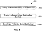
- a method 100 for making a cellular seal member 1 for a turbine includes, in sequence, forming 110 a diffusion aluminide coating on a surface of a cellular seal to form a coated cellular seal 10.
- the method also includes brazing 120 the coated cellular seal 10 to a seal substrate 50 to form the cellular seal member 1.
- the cellular seal member 1 includes the coated (aluminized) cellular seal 10, the seal substrate 50 and a braze joint 40 formed by brazing 120.
- the coated cellular seal 10 may have any cellular wall 12 structure, and includes cells 15 having hexagonal or honeycomb shapes.
- the coated cellular seal 10 having cells 15 that are hexagonal or honeycomb shape is herein equivalent to the term honeycomb seal 10.
- the method 100 includes forming 110 a diffusion aluminide coating 20 on a surface of an uncoated cellular seal to form a coated cellular seal 10.
- FIG. 1 provides a perspective view of a coated cellular seal 10 on which an aluminide coating 20 has been formed.
- the coated cellular seal 10 includes a plurality of individual, hexagonally-shaped cells 15.
- the coated cellular seal 10 may be formed from any suitable high temperature material, including various oxidation and hot corrosion resistant nickel-based, cobalt-based or iron-based superalloys, such as, for example, a nickel-based superalloy comprising 75% Ni, 16% Cr, 4.5% Al, 3% Fe, 0.05% C, 0.01% Y, 0.5% Mn, 0.2% Si, 0.1% Zr, and 0.01% B (in weight percent) sold commercially as e.g., Haynes 214®.
- the coated cellular seal 10 is configured to encounter conditions during operation of the gas turbine engine that can cause severe oxidation, corrosion and erosion.
- Coated cellular seal 10 is protected from the hostile environment of the turbine section by the diffusion aluminide coating 20, shown in FIG. 2 as being formed on a substrate region 22 of the coated cellular seal 10.
- the substrate region 22 may be the base superalloy of the coated cellular seal 10, or an overlay coating such as MCrAlY deposited by known methods on the surface of the coated cellular seal 10.
- the aluminide coating 20 develops an alumina (Al 2 O 3 ) layer or scale (not shown) on its surface that inhibits oxidation of the diffusion coating 20 and the underlying substrate region 22.
- the diffusion aluminide coating 20 overlies all surfaces 28, 29, 30, 31 of the individual cells 15 of coated cellular seal 10.
- the surfaces of the coated cellular seal 10 may be further protected by a thermal barrier coating (TBC) deposited on the aluminide coating 20, and the method 100 may optionally include depositing 130 a TBC on the coated cellular seal 10.
- TBC thermal barrier coating
- the TBC may be deposited by thermal spraying such as air plasma spraying (APS), low pressure plasma spraying (LPPS) and HVOF, or by a physical vapor deposition technique such as electron beam physical vapor deposition (EBPVD).
- Preferred TBC materials are zirconia partially stabilized with yttria (yttria-stabilized zirconia, or YSZ), though zirconia fully stabilized with yttria could be used, as well as zirconia stabilized by other oxides.
- the aluminide coating 20 is represented in FIG. 2 as having two distinct zones, an outermost of which is an additive layer 26 that contains environmentally-resistant intermetallic phases such as MAI, where M is iron, nickel or cobalt, depending on the substrate material.
- the chemistry of the additive layer 26 may be modified by the addition of elements, such as chromium, silicon, platinum, rhodium, hafnium, yttrium and zirconium, for the purpose of modifying the environmental and physical properties of the coating 20.
- a typical thickness for the additive layer 26 is up to about 75 micrometers.
- the diffusion zone 24 comprises various intermetallic and metastable phases that form during the coating reaction as a result of compositional or diffusional gradients and changes in elemental solubility in the local region of the substrate. These phases are distributed in a matrix of the substrate material.
- the diffusion aluminide coating 20 is formed by a slurry process by which aluminum is deposited and diffused into the surfaces 28 and 30 to form aluminide intermetallics.
- the slurry process makes use of a gel aluminum-containing slurry, the composition of which includes a donor material containing metallic aluminum, a halide activator, and a binder containing an organic polymer. Notably missing from the ingredients of the slurry compositions are inert fillers and inorganic binders. In the absence of inert fillers, whose particles are prone to sintering, the coating process and slurry composition of this invention are well-suited for use on an uncoated cellular seal to form the coated cellular seal 10 of FIGS. 1A-4 .
- Suitable donor materials are aluminum alloys with higher melting temperatures than aluminum (melting point of about 660°C).
- Particularly suitable donor metals include metallic aluminum alloyed with chromium, cobalt, iron, and/or another aluminum alloying agent with a sufficiently higher melting point so that the alloying agent does not deposit during the diffusion aluminiding process, but instead serves as an inert carrier for the aluminum of the donor material.
- Preferred donor materials are chromium-aluminum alloys.
- the donor material is in the form of a fine powder to reduce the likelihood that the donor material would become lodged or entrapped within the cellular seal during the coating process. For this reason, a preferred particle size for the donor material powder is -200 mesh (a maximum dimension of not larger than 74 micrometers), though it is foreseeable that powders with a mesh size of as large as 100 mesh (a maximum dimension of up to 149 micrometers) could be used.
- Suitable halide activators include ammonium chloride (NH 4 Cl), ammonium fluoride (NH 4 F), and ammonium bromide (NH4Br), though the use of other halide activators is also believed to be possible.
- Suitable activators must be capable of reacting with aluminum in the donor material to form a volatile aluminum halide (e.g., AlCl 3 , AlF 3 ) that reacts at the surfaces (e.g., used to form surfaces 28 and 30) of the uncoated cellular seal to deposit aluminum, which is then diffused into the surfaces 28 and 30 to form the diffusion aluminide coating 20 and coated cellular seal 10 as shown in FIGS. 2 and 3 .
- a volatile aluminum halide e.g., AlCl 3 , AlF 3
- a preferred activator for a given process will depend on what type of aluminide coating desired. For example, chloride activators promote a slower reaction to produce a thinner and/or outward-type coating, whereas fluoride activators promote a faster reaction capable of producing thicker and/or inward-type coatings.
- the activator is in a fine powder form. In some embodiments of the invention, the activator powder is preferably encapsulated to inhibit the absorption of moisture.
- Suitable binders preferably consist essentially or entirely of alcohol-based or water-based organic polymers.
- a preferred aspect of the invention is that the binder is able to burn off entirely and cleanly at temperatures below that required to vaporize and react the halide activator, with the remaining residue being essentially in the form of an ash that can be easily removed, for example, by forcing a gas such as air over the surfaces (e.g., surfaces 28 and 30) following the diffusion process.
- burn or “burn off' means raising the temperature to a point where the binder is removed by evaporating or boiling off.
- a water-based binder generally necessitates the above-noted encapsulation of the activator powder to prevent dissolution, while the use of an alcohol-based binder does not.
- suitable water-based organic polymeric binders include a polymeric gel available under the name Vitta Braz-Binder Gel available from the Vitta Corporation.
- Suitable alcohol-based binders can be low molecular weight polyalcohols (polyols), such as polyvinyl alcohol (PVA).
- the binder may also incorporate a cure catalyst or accelerant such as sodium hypophosphite. It is foreseeable that other alcohol or water-based organic polymeric binders could also be used.
- Suitable slurry compositions for use with this invention have a solids loading (donor material and activator) of about 10 to about 80 weight percent, with the balance binder. More particularly, suitable slurry compositions of this invention contain, by weight, about 35 to about 65% donor material powder, about 25 to about 60% binder, and about 1 to about 25% activator. More preferred ranges are, by weight, about 35 to about 65% donor material powder, about 25 to about 50% binder, and about 5 to about 25% activator. Within these ranges, the slurry composition has consistencies that allow its application to the external and internal surfaces of an uncoated cellular seal by a variety of methods, including spraying, dipping, brushing, injection, etc. where it can then be diffused to form the diffusion aluminide coating 20 on the surfaces 28, 29, 30 and 31 as described herein.
- slurries can be applied to have a nonuniform green state (i.e., undried) thicknesses, yet produce diffusion aluminide coatings of very uniform thickness.
- slurry coatings deposited to have thicknesses of about 0.010 inch (about 0.25 mm) to about 1 inch (about 25 mm) and greater have been shown to produce diffusion aluminide coatings whose thicknesses are very uniform, for example, varying by as little as about 0.0005 inch (about 0.01 mm) or less.
- slurry compositions of this invention can be applied to an uncoated cellular seal by brushing onto uncoated seal including application into the cells.
- Slurry compositions can also be applied by any suitable application method, including dipping an uncoated cellular seal into the slurry such as e.g., filling a trough or container with the slurry and placing the uncoated cellular seal face down into the slurry so that the cells are filled.
- slurry may be applied by pouring over an uncoated cellular seal to fill individual cells.
- the slurry could be applied to the cellular seal 10 by spraying onto all cells.
- the slurry could also be applied by pumping the slurry into the cells individually or all at one time. For some methods, the viscosity of the slurry may be decreased to facilitate application. Combinations of these and other techniques may be used to apply the slurry as well.
- the slurry coating composition is capable of producing diffusion aluminide coatings 20 over a broad range of diffusion treatment temperatures, generally in a range of about 815°C to about 1150°C. Within this broad range, the diffusion temperature can be tailored to preferentially produce either an inward or outward-type coating, along with the different properties associated with these different types of coatings.
- the high temperature capability of the slurry composition of this invention enables the production of an outward-type diffusion aluminide coating which, as previously noted, is typically more ductile, has a more stable nickel aluminide intermetallic phase, and exhibits better oxidation and LCF properties as compared to inward-type diffusion aluminide coatings. It is believed the particular types and amounts of donor material and activator can also be used to influence whether an inward or outward-type coating is produced within the above-noted treatment temperature range.
- the slurry-coated cellular seal can be immediately placed in a coating chamber (retort) to perform the diffusion process. Additional coating or activator materials are not required to be present in the retort, other than what is present in the slurry.
- the retort is evacuated and preferably backfilled with an inert or reducing atmosphere (such as argon or hydrogen, respectively).
- the temperature within the retort is then raised to a temperature sufficient to burn off the binder, for example about 150°C to about 200°C, with further heating being performed to attain the desired diffusion temperature as described above, during which time the activator is volatilized, the aluminum halide is formed, aluminum is deposited on the surfaces (e.g., surfaces 28 and 30) to form the coated cellular seal 10.
- the coated cellular seal 10 is held at the diffusion temperature for a duration of about one to about eight hours, again depending on the final thickness desired for the coating 20.
- the coated cellular seal 10 is removed from the retort and cleaned of any residues from the coating process remaining in and on the coated cellular seal 10.
- residues have been observed to be essentially limited to an ash-like residue of the binder and residue of donor material particles, the latter of which is primarily the metallic constituent (or constituents) of the donor material other than aluminum.
- the residues remaining following the coating process of this invention have been found to be readily removable, such as with forced gas flow, without resorting to more aggressive removal techniques such as wire brushing, glass bead or oxide grit burnishing, high pressure water jet, or other such methods that entail physical contact with a solid or liquid to remove firmly attached residues.
- the coating process of this invention is well suited for depositing aluminide coatings on surfaces (such as e.g., the surfaces of the coated cellular seal 10 that are internal) that cannot be reached by the aforementioned aggressive surface treatments.
- the thickness of the aluminide coating 20 may be controlled by controlling the initial thickness of the additive layer 26, as well as the temperature and time for which the aluminiding is performed. For example, treatment between 927°C and 1093°C for between about 2 to about 12 hours resulted in coating thicknesses on the seals of about 1.6 mils to about 2.6 mils.
- the method 100 also includes brazing 120 the coated cellular seal 10 to a seal substrate 50.
- the seal substrate 50 may be any suitable high temperature material, and in an exemplary embodiment may include various oxidation and hot corrosion resistant nickel-based, cobalt-based or iron-based superalloys, as described herein.
- the seal substrate 50 may comprise any suitable substrate shape or form, including those of various turbine engine components, and more particularly, may include a turbine shroud or liner.
- the seal substrate 50 has a substrate brazing surface 52 that is configured to receive a seal brazing surface 16 of the coated cellular seal 10.
- Brazing 120 may be performed by any suitable method. In an exemplary embodiment, brazing 120 may include applying a braze material 42 ( FIG.
- Braze material 42 comprises a nickel-based, cobalt-based or iron-based superalloy.
- braze material 42 includes a nickel-based superalloy having a composition, in weight percent of the alloy, of 7% Cr, 4.5% Si, 3% Fe, 3% B and the balance Ni and incidental impurities.
- heating the braze material 42, seal substrate 50 and coated cellular seal 10 sufficiently to form a braze joint 40 comprises heating to a temperature of about 1046°C (1915°F) for about 5 minutes.
- the braze material 42 may be applied as a sheet or foil to either or both of the seal substrate 50 or the coated cellular seal 10, and may be held in place by a tack weld or other temporary joint.
- the braze material may be applied to either or both of the seal substrate 50 or the coated cellular seal 10 as a powder, paste, slurry or the like by painting, dipping, spraying, screen printing, calendar rolls or any other suitable method of application.
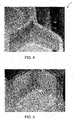
- the braze joint 40 is shown schematically in FIG. 1C and 3 and in the photograph of FIG. 4 .
- the formation of the aluminide layer 20 on the coated cellular seal 10 prior to brazing 120 is very advantageous because the braze material 42 tends to form a fillet 44 and wetting of the walls 12 of the cellular seal is limited to the area of the fillet 44, which is proximate the seal brazing surface 16 of the cellular seal and the substrate brazing surface 52 of the seal substrate 50. It also enables the braze material 42 to have a lower melting point and the brazing 120 to be performed at a lower temperature than is the case if the aluminiding is performed after brazing. This is in contrast to what may occur if the braze joint 60 is formed prior forming the aluminide coating on the uncoated cellular seal as shown comparatively in FIG. 5 .
- forming the aluminide coating causes the braze material 62 to remelt and be transported by capillarity or other transport mechanisms away from the surfaces and along the corners or edges of the cells away from the braze joint. This action weakens the braze joint and causes the formation of brittle phases 64 along the edges, which can impede the action of the seal or cause greater wear of turbine components that touch the degradable seal.
Description
- The present invention relates to a method of making a cellular (e.g. honeycomb) seal as may be used, for example, in a turbine.
- Honeycomb seals are used in multiple locations in various gas turbines. For example, such seals may be used against the rails on shrouded buckets as an abradable material. The temperatures encountered at these locations can be relatively high, including 870°C or more. Unfortunately, even a honeycomb material made from an oxidation resistant alloy can experience oxidation and a shortening of useful life under these conditions. For this reason, advances in high temperature capabilities have been achieved through the development of iron, nickel and cobalt-based superalloys for making honeycomb materials and the use of oxidation-resistant environmental coatings capable of protecting superalloys from oxidation, hot corrosion, etc. For example, Haynes 214® (provided by Haynes International of Kokomo, Indiana) is an oxidation-resistant alloy constructed from 75 Ni, 16 Cr, 4.5 Al, 3 Fe, 0.05 C, 0.01 Y, 0.5 Mn, 0.2 Si, 0.1 Zr, and 0.01 B (by weight percent). However, even when constructed from this material, the expected life of a honeycomb seal in
stage 2 shrouds can be less than 20,000 hours. - Aluminum-containing coatings, particularly diffusion aluminide coatings, have found widespread use as environmental coatings on gas turbine engine components. During high temperature exposure in air, aluminum-containing coatings form a protective aluminum oxide (alumina) scale or layer that inhibits corrosion and oxidation of the coating and the underlying substrate. Diffusion coatings can be generally characterized as having an additive layer that primarily overlies the original surface of the coated substrate and a diffusion zone below the original surface. The additive layer of a diffusion aluminide coating contains the environmentally-resistant intermetallic phase MAI, where M is iron, nickel or cobalt, depending on the substrate material (mainly β(NiAl) if the substrate is Ni-base). The diffusion zone comprises various intermetallic and metastable phases that form during the coating reaction as a result of compositional gradients and changes in elemental solubility in the local region of the substrate.
- Diffusion aluminide coatings are generally formed by depositing and diffusing aluminum into the surface of a component at temperatures at or above about 760°C. Notable processes include pack cementation and vapor phase aluminiding (VPA) techniques, and diffusing aluminum deposited by chemical vapor deposition (CVD), slurry coating, or another deposition process. Aluminum deposited by slurry coating is typically diffused without an activator in contrast to the other methods, relying instead on melting and subsequent diffusion of the deposited aluminum.
- The processing temperature and whether an activator is used will influence whether a diffusion coating is categorized as an outward-type or inward-type. Outward-type coatings are formed as a result of using higher temperatures (e.g., at or above the solution temperature of the alloy being coated) and lower amounts of activator as compared to inward-type coatings. In the case of a nickel-based substrate, such conditions promote the outward diffusion of nickel from the substrate into the deposited aluminum layer to form the additive layer, and also reduce the inward diffusion of aluminum from the deposited aluminum layer into the substrate, resulting in a relatively thick additive layer above the original surface of the substrate. Conversely, lower processing temperatures and larger amounts of activator reduce the outward diffusion of nickel from the substrate into the deposited aluminum layer and promote the inward diffusion of aluminum from the deposited aluminum layer into the substrate, yielding an inward-type diffusion coating characterized by an additive layer that extends below the original surface of the substrate.
- The choice of donor material influences whether an outward or inward-type diffusion coating can be produced since aluminum alloys such as CrAl, CoAl, FeAl, TiAl, etc., have higher melting temperatures than unalloyed aluminum and, therefore, can be used with the higher processing temperatures used to form outward-type coatings. Though both outward and inward-type diffusion aluminide coatings are successfully used, outward-type diffusion aluminide coatings typically have a more ductile and stable nickel aluminide intermetallic phase and exhibit better oxidation and low cycle fatigue (LCF) properties as compared to inward-type diffusion aluminide coatings.
- Slurries used to form diffusion aluminide coatings are typically aluminum-rich, containing only an unalloyed aluminum powder in an inorganic binder. The slurry is directly applied to surfaces to be aluminized, and aluminiding occurs as a result of heating the component in a non-oxidizing atmosphere or vacuum to a temperature above about 760°C, which is maintained for a duration sufficient to melt the aluminum powder and diffuse the molten aluminum into the surface. The thickness of a diffusion aluminide coating produced by a slurry method is typically proportional to the amount of the slurry applied to the surface, and as such, the amount of slurry applied must be very carefully controlled.
- The difficulty of consistently producing diffusion aluminide coatings of uniform thickness has discouraged the use of slurry processes on components that require a very uniform diffusion coating and/or have complicated geometries. As a result, though capable of forming diffusion aluminide coatings on internal and external surfaces, slurry coating processes have been typically employed to coat limited, noncritical regions of gas turbine engines. Another limitation of slurry coating processes is that, because of the use of unalloyed aluminum, they are typically performed at relatively low temperatures (e.g., below 980°C), and are therefore limited to producing an inward-type coating with high aluminum content.
- Document
US 2002/0158417 A1 describes a method of joining/attaching an aluminized honeycomb seal on a superalloy turbine component by brazing the honeycomb onto the component. The region of attachment of the honeycomb to the backing plate/structure may be masked before the brazing step or the coating is applied after brazing the honeycomb to the backing structure. DocumentDE 102 38 551 A1 describes a method for the production of a composite component by joining a structure to a support by soldering using aluminum as the solder material. The structure and the support are made from high melting alloys made from iron, nickel, cobalt, chromium, titanium or other combination. - A method and composition for coating honeycomb seals and, more specifically, a method and slurry for applying an aluminide coating onto honeycomb seals is described in
US2011/0074113 to Cavanaugh et al. The method includes preparing a slurry of a powder containing a metallic aluminum alloy having a melting temperature higher than aluminum, an activator capable of forming a reactive halide vapor with the metallic aluminum, and a binder containing an organic polymer. The slurry is applied to surfaces of the honeycomb seal, which is then heated to remove or burn off the binder, vaporize and react the activator with the metallic aluminum to form the halide vapor, react the halide vapor at the substrate surfaces to deposit aluminum on the surfaces of the seal, and diffuse the deposited aluminum into the surfaces to form a diffusion aluminide coating. While this process is very useful for forming an aluminide coating on honeycomb materials attached to superalloy substrates, various issues have been observed, including entrapment of residue from the aluminiding process in the cells, and migration of braze materials used to attach the cellular seal to the seal substrate within the cells during aluminiding where they may form undesirable compounds. Therefore, an improved method for making aluminized cellular seals is very desirable. - According to the invention, a method for making a honeycomb seal for a turbine is provided, as defined in
claim 1. - These and other advantages and features will become more apparent from the following description taken in conjunction with the drawings.
- The subject matter, which is regarded as the invention, is particularly pointed out and distinctly claimed in the claims at the conclusion of the specification. The foregoing and other features, and advantages of the invention are apparent from the following detailed description taken in conjunction with the accompanying drawings in which:
A full and enabling disclosure of the present invention, including the best mode thereof, directed to one of ordinary skill in the art, is set forth in the specification, which makes reference to the appended figures, in which: -
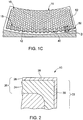
FIGS. 1A-1C are perspective partial cross-sectional views illustrating an exemplary embodiment of a method of making a cellular seal member; -
FIG. 2 is a partial cross-sectional view ofsection 2--2 ofFIG. 1A illustrating a portion of a cellular seal illustrating an exemplary embodiment of a diffusion aluminide coating as may be applied to an internal or an external surface of the seal, or to both surfaces; -
FIG. 3 is a cross-sectional view ofsection 3--3 ofFIG. 1C illustrating an exemplary embodiment of a braze joint as disclosed herein; -
FIG. 4 is a photograph of an exemplary embodiment of a cellular seal member and braze joint as disclosed herein; -
FIG. 5 is a photograph of comparative cellular seal member and braze joint; and -
FIG. 6 is a flow chart of an exemplary embodiment of a method of making a cellular seal as disclosed herein. - The detailed description explains embodiments of the invention, together with advantages and features, by way of example with reference to the drawings.
- Referring to the Figures, and particularly
FIGS. 1A-1C and6 , in an exemplary embodiment, amethod 100 for making acellular seal member 1 for a turbine is disclosed. The method includes, in sequence, forming 110 a diffusion aluminide coating on a surface of a cellular seal to form a coatedcellular seal 10. The method also includes brazing 120 the coatedcellular seal 10 to aseal substrate 50 to form thecellular seal member 1. Thecellular seal member 1 includes the coated (aluminized)cellular seal 10, theseal substrate 50 and abraze joint 40 formed by brazing 120. The coatedcellular seal 10 may have anycellular wall 12 structure, and includescells 15 having hexagonal or honeycomb shapes. The coatedcellular seal 10 havingcells 15 that are hexagonal or honeycomb shape is herein equivalent to theterm honeycomb seal 10. - The
method 100 includes forming 110 adiffusion aluminide coating 20 on a surface of an uncoated cellular seal to form a coatedcellular seal 10.FIG. 1 provides a perspective view of a coatedcellular seal 10 on which analuminide coating 20 has been formed. The coatedcellular seal 10 includes a plurality of individual, hexagonally-shaped cells 15. The coatedcellular seal 10 may be formed from any suitable high temperature material, including various oxidation and hot corrosion resistant nickel-based, cobalt-based or iron-based superalloys, such as, for example, a nickel-based superalloy comprising 75% Ni, 16% Cr, 4.5% Al, 3% Fe, 0.05% C, 0.01% Y, 0.5% Mn, 0.2% Si, 0.1% Zr, and 0.01% B (in weight percent) sold commercially as e.g., Haynes 214®. The coatedcellular seal 10 is configured to encounter conditions during operation of the gas turbine engine that can cause severe oxidation, corrosion and erosion. - Coated
cellular seal 10 is protected from the hostile environment of the turbine section by thediffusion aluminide coating 20, shown inFIG. 2 as being formed on asubstrate region 22 of the coatedcellular seal 10. Thesubstrate region 22 may be the base superalloy of the coatedcellular seal 10, or an overlay coating such as MCrAlY deposited by known methods on the surface of the coatedcellular seal 10. When subjected to sufficiently high temperatures in an oxidizing atmosphere, thealuminide coating 20 develops an alumina (Al2O3) layer or scale (not shown) on its surface that inhibits oxidation of thediffusion coating 20 and theunderlying substrate region 22. Thediffusion aluminide coating 20 overlies allsurfaces individual cells 15 of coatedcellular seal 10. - The surfaces of the coated
cellular seal 10 may be further protected by a thermal barrier coating (TBC) deposited on thealuminide coating 20, and themethod 100 may optionally include depositing 130 a TBC on the coatedcellular seal 10. The TBC may be deposited by thermal spraying such as air plasma spraying (APS), low pressure plasma spraying (LPPS) and HVOF, or by a physical vapor deposition technique such as electron beam physical vapor deposition (EBPVD). Preferred TBC materials are zirconia partially stabilized with yttria (yttria-stabilized zirconia, or YSZ), though zirconia fully stabilized with yttria could be used, as well as zirconia stabilized by other oxides. - The
aluminide coating 20 is represented inFIG. 2 as having two distinct zones, an outermost of which is anadditive layer 26 that contains environmentally-resistant intermetallic phases such as MAI, where M is iron, nickel or cobalt, depending on the substrate material. The chemistry of theadditive layer 26 may be modified by the addition of elements, such as chromium, silicon, platinum, rhodium, hafnium, yttrium and zirconium, for the purpose of modifying the environmental and physical properties of thecoating 20. A typical thickness for theadditive layer 26 is up to about 75 micrometers. - Beneath the
additive layer 26 is a diffusion zone (DZ) 24 that typically extends about 25 to 50 micrometers into thesubstrate region 22. Thediffusion zone 24 comprises various intermetallic and metastable phases that form during the coating reaction as a result of compositional or diffusional gradients and changes in elemental solubility in the local region of the substrate. These phases are distributed in a matrix of the substrate material. - The
diffusion aluminide coating 20 is formed by a slurry process by which aluminum is deposited and diffused into thesurfaces cellular seal 10 ofFIGS. 1A-4 . - Suitable donor materials are aluminum alloys with higher melting temperatures than aluminum (melting point of about 660°C). Particularly suitable donor metals include metallic aluminum alloyed with chromium, cobalt, iron, and/or another aluminum alloying agent with a sufficiently higher melting point so that the alloying agent does not deposit during the diffusion aluminiding process, but instead serves as an inert carrier for the aluminum of the donor material. Preferred donor materials are chromium-aluminum alloys.
- An alloy that appears to be particularly well-suited for diffusion processes performed over the wide range of temperatures contemplated by this invention is believed to be 56Cr-44Al (about 44 weight percent aluminum, the balance chromium and incidental impurities). The donor material is in the form of a fine powder to reduce the likelihood that the donor material would become lodged or entrapped within the cellular seal during the coating process. For this reason, a preferred particle size for the donor material powder is -200 mesh (a maximum dimension of not larger than 74 micrometers), though it is foreseeable that powders with a mesh size of as large as 100 mesh (a maximum dimension of up to 149 micrometers) could be used.
- Suitable halide activators include ammonium chloride (NH4Cl), ammonium fluoride (NH4F), and ammonium bromide (NH4Br), though the use of other halide activators is also believed to be possible. Suitable activators must be capable of reacting with aluminum in the donor material to form a volatile aluminum halide (e.g., AlCl3, AlF3) that reacts at the surfaces (e.g., used to form
surfaces 28 and 30) of the uncoated cellular seal to deposit aluminum, which is then diffused into thesurfaces diffusion aluminide coating 20 and coatedcellular seal 10 as shown inFIGS. 2 and3 . A preferred activator for a given process will depend on what type of aluminide coating desired. For example, chloride activators promote a slower reaction to produce a thinner and/or outward-type coating, whereas fluoride activators promote a faster reaction capable of producing thicker and/or inward-type coatings. For use in the slurry, the activator is in a fine powder form. In some embodiments of the invention, the activator powder is preferably encapsulated to inhibit the absorption of moisture. - Suitable binders preferably consist essentially or entirely of alcohol-based or water-based organic polymers. A preferred aspect of the invention is that the binder is able to burn off entirely and cleanly at temperatures below that required to vaporize and react the halide activator, with the remaining residue being essentially in the form of an ash that can be easily removed, for example, by forcing a gas such as air over the surfaces (e.g., surfaces 28 and 30) following the diffusion process. As used herein, "burn" or "burn off' means raising the temperature to a point where the binder is removed by evaporating or boiling off. The use of a water-based binder generally necessitates the above-noted encapsulation of the activator powder to prevent dissolution, while the use of an alcohol-based binder does not. Commercial examples of suitable water-based organic polymeric binders include a polymeric gel available under the name Vitta Braz-Binder Gel available from the Vitta Corporation. Suitable alcohol-based binders can be low molecular weight polyalcohols (polyols), such as polyvinyl alcohol (PVA). The binder may also incorporate a cure catalyst or accelerant such as sodium hypophosphite. It is foreseeable that other alcohol or water-based organic polymeric binders could also be used.
- Suitable slurry compositions for use with this invention have a solids loading (donor material and activator) of about 10 to about 80 weight percent, with the balance binder. More particularly, suitable slurry compositions of this invention contain, by weight, about 35 to about 65% donor material powder, about 25 to about 60% binder, and about 1 to about 25% activator. More preferred ranges are, by weight, about 35 to about 65% donor material powder, about 25 to about 50% binder, and about 5 to about 25% activator. Within these ranges, the slurry composition has consistencies that allow its application to the external and internal surfaces of an uncoated cellular seal by a variety of methods, including spraying, dipping, brushing, injection, etc. where it can then be diffused to form the
diffusion aluminide coating 20 on thesurfaces - In one exemplary aspect of the invention, slurries can be applied to have a nonuniform green state (i.e., undried) thicknesses, yet produce diffusion aluminide coatings of very uniform thickness. For example, slurry coatings deposited to have thicknesses of about 0.010 inch (about 0.25 mm) to about 1 inch (about 25 mm) and greater have been shown to produce diffusion aluminide coatings whose thicknesses are very uniform, for example, varying by as little as about 0.0005 inch (about 0.01 mm) or less.
- As a result, slurry compositions of this invention can be applied to an uncoated cellular seal by brushing onto uncoated seal including application into the cells. Slurry compositions can also be applied by any suitable application method, including dipping an uncoated cellular seal into the slurry such as e.g., filling a trough or container with the slurry and placing the uncoated cellular seal face down into the slurry so that the cells are filled. By way of further example, slurry may be applied by pouring over an uncoated cellular seal to fill individual cells. The slurry could be applied to the
cellular seal 10 by spraying onto all cells. The slurry could also be applied by pumping the slurry into the cells individually or all at one time. For some methods, the viscosity of the slurry may be decreased to facilitate application. Combinations of these and other techniques may be used to apply the slurry as well. - Another advantageous aspect of certain embodiments of the present invention is that the slurry coating composition is capable of producing
diffusion aluminide coatings 20 over a broad range of diffusion treatment temperatures, generally in a range of about 815°C to about 1150°C. Within this broad range, the diffusion temperature can be tailored to preferentially produce either an inward or outward-type coating, along with the different properties associated with these different types of coatings. - For example, the high temperature capability of the slurry composition of this invention enables the production of an outward-type diffusion aluminide coating which, as previously noted, is typically more ductile, has a more stable nickel aluminide intermetallic phase, and exhibits better oxidation and LCF properties as compared to inward-type diffusion aluminide coatings. It is believed the particular types and amounts of donor material and activator can also be used to influence whether an inward or outward-type coating is produced within the above-noted treatment temperature range.
- After applying the slurry to the surfaces (e.g. surfaces 28 and 30 as shown in
FIG. 2 ) of the uncoated cellular seal, the slurry-coated cellular seal can be immediately placed in a coating chamber (retort) to perform the diffusion process. Additional coating or activator materials are not required to be present in the retort, other than what is present in the slurry. The retort is evacuated and preferably backfilled with an inert or reducing atmosphere (such as argon or hydrogen, respectively). The temperature within the retort is then raised to a temperature sufficient to burn off the binder, for example about 150°C to about 200°C, with further heating being performed to attain the desired diffusion temperature as described above, during which time the activator is volatilized, the aluminum halide is formed, aluminum is deposited on the surfaces (e.g., surfaces 28 and 30) to form the coatedcellular seal 10. The coatedcellular seal 10 is held at the diffusion temperature for a duration of about one to about eight hours, again depending on the final thickness desired for thecoating 20. - Following the coating process, the coated
cellular seal 10 is removed from the retort and cleaned of any residues from the coating process remaining in and on the coatedcellular seal 10. Such residues have been observed to be essentially limited to an ash-like residue of the binder and residue of donor material particles, the latter of which is primarily the metallic constituent (or constituents) of the donor material other than aluminum. In any case, the residues remaining following the coating process of this invention have been found to be readily removable, such as with forced gas flow, without resorting to more aggressive removal techniques such as wire brushing, glass bead or oxide grit burnishing, high pressure water jet, or other such methods that entail physical contact with a solid or liquid to remove firmly attached residues. Because of the ease with which the residues can be removed, the coating process of this invention is well suited for depositing aluminide coatings on surfaces (such as e.g., the surfaces of the coatedcellular seal 10 that are internal) that cannot be reached by the aforementioned aggressive surface treatments. - The thickness of the
aluminide coating 20 may be controlled by controlling the initial thickness of theadditive layer 26, as well as the temperature and time for which the aluminiding is performed. For example, treatment between 927°C and 1093°C for between about 2 to about 12 hours resulted in coating thicknesses on the seals of about 1.6 mils to about 2.6 mils. - Referring again to
FIGS. 1A-1C , themethod 100 also includes brazing 120 the coatedcellular seal 10 to aseal substrate 50. Theseal substrate 50 may be any suitable high temperature material, and in an exemplary embodiment may include various oxidation and hot corrosion resistant nickel-based, cobalt-based or iron-based superalloys, as described herein. Theseal substrate 50 may comprise any suitable substrate shape or form, including those of various turbine engine components, and more particularly, may include a turbine shroud or liner. Theseal substrate 50 has asubstrate brazing surface 52 that is configured to receive aseal brazing surface 16 of the coatedcellular seal 10. Brazing 120 may be performed by any suitable method. In an exemplary embodiment, brazing 120 may include applying a braze material 42 (FIG. 1B ) to at least one of the coatedcellular seal 10 or theseal substrate 50 and heating thebraze material 42,seal substrate 50 and coatedcellular seal 10 sufficiently to form a braze joint 40 (FIG. 1C ).Braze material 42 comprises a nickel-based, cobalt-based or iron-based superalloy. In one embodiment,braze material 42 includes a nickel-based superalloy having a composition, in weight percent of the alloy, of 7% Cr, 4.5% Si, 3% Fe, 3% B and the balance Ni and incidental impurities. In an exemplary embodiment, heating thebraze material 42,seal substrate 50 and coatedcellular seal 10 sufficiently to form a braze joint 40 comprises heating to a temperature of about 1046°C (1915°F) for about 5 minutes. In an exemplary embodiment, thebraze material 42 may be applied as a sheet or foil to either or both of theseal substrate 50 or the coatedcellular seal 10, and may be held in place by a tack weld or other temporary joint. In another embodiment, the braze material may be applied to either or both of theseal substrate 50 or the coatedcellular seal 10 as a powder, paste, slurry or the like by painting, dipping, spraying, screen printing, calendar rolls or any other suitable method of application. The braze joint 40 is shown schematically inFIG. 1C and3 and in the photograph ofFIG. 4 . The formation of thealuminide layer 20 on the coatedcellular seal 10 prior tobrazing 120 is very advantageous because thebraze material 42 tends to form afillet 44 and wetting of thewalls 12 of the cellular seal is limited to the area of thefillet 44, which is proximate theseal brazing surface 16 of the cellular seal and thesubstrate brazing surface 52 of theseal substrate 50. It also enables thebraze material 42 to have a lower melting point and thebrazing 120 to be performed at a lower temperature than is the case if the aluminiding is performed after brazing. This is in contrast to what may occur if the braze joint 60 is formed prior forming the aluminide coating on the uncoated cellular seal as shown comparatively inFIG. 5 . In this case, forming the aluminide coating causes thebraze material 62 to remelt and be transported by capillarity or other transport mechanisms away from the surfaces and along the corners or edges of the cells away from the braze joint. This action weakens the braze joint and causes the formation ofbrittle phases 64 along the edges, which can impede the action of the seal or cause greater wear of turbine components that touch the degradable seal.
Claims (15)
- A method (100) for making a honeycomb seal member (1) for a turbine, comprising, in sequence:forming (110) a diffusion aluminide coating (20) on all surfaces (16, 28, 29, 30, 31) of a honeycomb seal (10) to form a coated honeycomb seal (10); one of the surfaces comprising a seal brazing surface (16); andbrazing (120) the seal brazing surface (16) of the coated honeycomb seal (10) to a substrate brazing surface (52) of a seal substrate (50) with a braze material (42) comprising a nickel-based, cobalt-based or iron-based superalloy to form a braze joint (40)wherein the braze material (42) forms a fillet (44) and wetting of the walls (12) of the honeycomb seal (10) is limited to the area of the fillet (44), which is proximate the seal brazing surface (16) of the honeycomb seal (10) and the substrate brazing surface (52) of the seal substrate 50, wherein forming the diffusion aluminide coating (20) comprises:preparing a gel aluminide slurry comprising a powder containing a metallic aluminum alloy having a melting temperature higher than aluminum, an activator capable of forming a reactive halide vapor with aluminum in the aluminum alloy, and a binder containing at least one organic polymer;applying the gel aluminide slurry onto the surfaces of the honeycomb seal;heating the honeycomb seal to remove the binder, vaporize and react the activator with the metallic aluminum to form the halide vapor, react the halide vapor at the surfaces of the honeycomb seal to deposit aluminum on the surfaces, and diffuse the deposited aluminum into the surfaces of the honeycomb seal to form a diffusion aluminide coating, wherein the binder is removed to form a readily removable ash residue.
- A method according to claim 1, wherein the seal substrate (50) comprises a component of a turbine engine.
- A method according to claim 2, wherein the component comprises a turbine shroud, bucket nozzle, liner.
- A method according to claim 2 or claim 3, wherein the component comprises a nickel-based, cobalt-based or iron-based superalloy.
- A method according to any preceding claim, wherein brazing comprises:applying a braze material (42) to at least one of the honeycomb seal (10) or the seal substrate (50); andheating the braze material (42), seal substrate (50) and honeycomb seal (10) sufficiently to form a braze joint (40) .
- A method according to claim 5, wherein heating comprises heating to a temperature of 1046°C (1915°F) for 5 minutes.
- A method according to claim 1, wherein the powder contains a chromium-aluminum alloy.
- A method according to claim 1 or claim 7, wherein the powder has a particle size of up to 149 micrometers (100 mesh).
- A method according to any one of claims 1, 7 and 8, wherein the activator is chosen from the group consisting of ammonium chloride, ammonium fluoride, and ammonium bromide.
- A method according to any one of claims 1 and 7 to 9, wherein the binder consists of the at least one organic polymer.
- A method according to anyone of claims 1 and 7 to 10, wherein the slurry consists essentially of, by weight, 35 to 65% of the powder, 1 to 25% of the activator, and 25 to 60% of the binder.
- A method according to any one of claims 1 and 7, wherein the honeycomb seals with gel aluminide slurry are heated to a temperature within a range of 815°C to 1150°C.
- A method according to any preceding claim, wherein the diffusion aluminide coating is an inward-type coating or an outward-type coating.
- A method according to any preceding claim, further comprising depositing a TBC coating on the coated honeycomb seal following brazing.
- A method according to any preceding claim, wherein the honeycomb seal is formed of a nickel-based superalloy, a Co-based superalloy, or a Fe-based superalloy.
Applications Claiming Priority (1)
| Application Number | Priority Date | Filing Date | Title |
|---|---|---|---|
| US13/344,058 US8973808B2 (en) | 2012-01-05 | 2012-01-05 | Method for making a cellular seal |
Publications (3)
| Publication Number | Publication Date |
|---|---|
| EP2612951A2 EP2612951A2 (en) | 2013-07-10 |
| EP2612951A3 EP2612951A3 (en) | 2016-03-16 |
| EP2612951B1 true EP2612951B1 (en) | 2020-10-28 |
Family
ID=47435810
Family Applications (1)
| Application Number | Title | Priority Date | Filing Date |
|---|---|---|---|
| EP12198665.7A Active EP2612951B1 (en) | 2012-01-05 | 2012-12-20 | Method for making a honeycomb seal |
Country Status (4)
| Country | Link |
|---|---|
| US (1) | US8973808B2 (en) |
| EP (1) | EP2612951B1 (en) |
| JP (1) | JP6205128B2 (en) |
| HU (1) | HUE053283T2 (en) |
Families Citing this family (17)
| Publication number | Priority date | Publication date | Assignee | Title |
|---|---|---|---|---|
| PL223710B1 (en) * | 2012-12-12 | 2016-10-31 | Aic Spółka Z Ograniczoną Odpowiedzialnością | Soldering element |
| US20150375259A1 (en) * | 2014-06-27 | 2015-12-31 | General Electric Company | Method and apparatus for manufacturing pre-coated honeycomb segments for turbomachines |
| US20160319690A1 (en) * | 2015-04-30 | 2016-11-03 | General Electric Company | Additive manufacturing methods for turbine shroud seal structures |
| CN106541221A (en) * | 2015-09-21 | 2017-03-29 | 北京安达泰克科技有限公司 | The solder paste dipped and its preparation technology and using method |
| EP3228826B1 (en) * | 2016-04-05 | 2021-03-17 | MTU Aero Engines GmbH | Seal segment arrangement having a connector, corresponding gas turbine engine and method of manufacturing |
| US10053779B2 (en) | 2016-06-22 | 2018-08-21 | General Electric Company | Coating process for applying a bifurcated coating |
| US10718352B2 (en) | 2016-07-26 | 2020-07-21 | Rolls-Royce Corporation | Multi-cellular abradable liner |
| US10077494B2 (en) | 2016-09-13 | 2018-09-18 | General Electric Company | Process for forming diffusion coating on substrate |
| US10024185B2 (en) * | 2016-09-21 | 2018-07-17 | General Electric Company | Braze gel, brazing process, and brazing article |
| US10369630B2 (en) * | 2017-02-24 | 2019-08-06 | General Electric Company | Polyhedral-sealed article and method for forming polyhedral-sealed article |
| US10774670B2 (en) * | 2017-06-07 | 2020-09-15 | General Electric Company | Filled abradable seal component and associated methods thereof |
| US10109383B1 (en) * | 2017-08-15 | 2018-10-23 | General Electric Company | Target assembly and nuclide production system |
| US10822964B2 (en) * | 2018-11-13 | 2020-11-03 | Raytheon Technologies Corporation | Blade outer air seal with non-linear response |
| US10920618B2 (en) | 2018-11-19 | 2021-02-16 | Raytheon Technologies Corporation | Air seal interface with forward engagement features and active clearance control for a gas turbine engine |
| US10934941B2 (en) | 2018-11-19 | 2021-03-02 | Raytheon Technologies Corporation | Air seal interface with AFT engagement features and active clearance control for a gas turbine engine |
| EP3945246B1 (en) * | 2020-07-27 | 2024-02-07 | Ansaldo Energia Switzerland AG | Gas turbine for power plants having a honeycomb seal device |
| US11370070B1 (en) | 2021-02-26 | 2022-06-28 | Raytheon Technologies Corporation | Repair methods and systems for honeycomb structures in gas turbine engines |
Family Cites Families (13)
| Publication number | Priority date | Publication date | Assignee | Title |
|---|---|---|---|---|
| US2856281A (en) * | 1954-10-05 | 1958-10-14 | Solar Aircraft Co | High temperature brazing alloys |
| US3084770A (en) * | 1957-09-03 | 1963-04-09 | Martin Marietta Corp | Brazed honeycomb structures |
| US3478413A (en) | 1966-05-09 | 1969-11-18 | Trw Inc | Aluminide coating braze stop-off |
| US3342563A (en) * | 1967-01-03 | 1967-09-19 | Gen Electric | Cellular material and method for making |
| JPH05202701A (en) * | 1992-01-28 | 1993-08-10 | Mitsubishi Heavy Ind Ltd | Joining method |
| US5702050A (en) * | 1995-04-28 | 1997-12-30 | Mitsubishi Jukogyo Kabushiki Kaisha | Method of brazing a honeycomb |
| JP2002126868A (en) * | 2000-10-20 | 2002-05-08 | Mitsubishi Heavy Ind Ltd | Manufacturing method for member including groove inside |
| US6610416B2 (en) * | 2001-04-26 | 2003-08-26 | General Electric Company | Material treatment for reduced cutting energy and improved temperature capability of honeycomb seals |
| IES20010834A2 (en) * | 2001-09-17 | 2003-03-19 | Sifco Res & Dev Ltd | Component repair materials |
| DE10238551A1 (en) * | 2002-08-22 | 2004-03-04 | Rolls-Royce Deutschland Ltd & Co Kg | Production of a composite component used as a sealing element in gas turbines comprises joining a structure to a support by soldering using aluminum as the solder material |
| US20040200549A1 (en) * | 2002-12-10 | 2004-10-14 | Cetel Alan D. | High strength, hot corrosion and oxidation resistant, equiaxed nickel base superalloy and articles and method of making |
| US8916005B2 (en) | 2007-11-15 | 2014-12-23 | General Electric Company | Slurry diffusion aluminide coating composition and process |
| US8318251B2 (en) | 2009-09-30 | 2012-11-27 | General Electric Company | Method for coating honeycomb seal using a slurry containing aluminum |
-
2012
- 2012-01-05 US US13/344,058 patent/US8973808B2/en active Active
- 2012-12-20 EP EP12198665.7A patent/EP2612951B1/en active Active
- 2012-12-20 JP JP2012277542A patent/JP6205128B2/en active Active
- 2012-12-20 HU HUE12198665A patent/HUE053283T2/en unknown
Non-Patent Citations (1)
| Title |
|---|
| None * |
Also Published As
| Publication number | Publication date |
|---|---|
| HUE053283T2 (en) | 2021-06-28 |
| US8973808B2 (en) | 2015-03-10 |
| JP2013139780A (en) | 2013-07-18 |
| EP2612951A3 (en) | 2016-03-16 |
| US20130175325A1 (en) | 2013-07-11 |
| EP2612951A2 (en) | 2013-07-10 |
| JP6205128B2 (en) | 2017-09-27 |
Similar Documents
| Publication | Publication Date | Title |
|---|---|---|
| EP2612951B1 (en) | Method for making a honeycomb seal | |
| US8318251B2 (en) | Method for coating honeycomb seal using a slurry containing aluminum | |
| EP2060653B1 (en) | Slurry diffusion aluminide coating composition and process | |
| EP1839800B1 (en) | Method for local application of diffusion aluminide coating | |
| JP4549490B2 (en) | Method for simultaneously aluminizing nickel-base and cobalt-base superalloys | |
| CN105899707B (en) | Method for applying chromium diffusion coatings on selected regions of a component | |
| EP0933448A1 (en) | Improved diffusion aluminide bond coat for a thermal barrier coating system and a method therefor | |
| JP4615677B2 (en) | Method for controlling the thickness and aluminum content of diffusion aluminide coatings | |
| US20120324902A1 (en) | Method of maintaining surface-related properties of gas turbine combustor components | |
| EP1528117B1 (en) | Diffusion coating process | |
| EP2022868A2 (en) | Method for forming platinum aluminide diffusion coatings | |
| US20100124670A1 (en) | Coated components and methods of fabricating coated components and coated turbine disks | |
| EP2886677B1 (en) | A slurry and a coating method | |
| EP0739427B1 (en) | Improved pack coating process for articles containing small passageways | |
| EP1091013A1 (en) | Method for forming a coating by use of an activated foam technique | |
| EP3351653A1 (en) | Aluminide diffusion coating system and process for forming an aluminide diffusion coating system | |
| US20050265851A1 (en) | Active elements modified chromium diffusion patch coating | |
| EP3144409A1 (en) | Thermal barrier coating system and processes for forming a thermal barrier coating system | |
| EP2020452A2 (en) | Method for forming aluminide diffusion coatings | |
| EP3475459B1 (en) | Coating process for applying a bifurcated coating |
Legal Events
| Date | Code | Title | Description |
|---|---|---|---|
| PUAI | Public reference made under article 153(3) epc to a published international application that has entered the european phase |
Free format text: ORIGINAL CODE: 0009012 |
|
| AK | Designated contracting states |
Kind code of ref document: A2 Designated state(s): AL AT BE BG CH CY CZ DE DK EE ES FI FR GB GR HR HU IE IS IT LI LT LU LV MC MK MT NL NO PL PT RO RS SE SI SK SM TR |
|
| AX | Request for extension of the european patent |
Extension state: BA ME |
|
| PUAL | Search report despatched |
Free format text: ORIGINAL CODE: 0009013 |
|
| AK | Designated contracting states |
Kind code of ref document: A3 Designated state(s): AL AT BE BG CH CY CZ DE DK EE ES FI FR GB GR HR HU IE IS IT LI LT LU LV MC MK MT NL NO PL PT RO RS SE SI SK SM TR |
|
| AX | Request for extension of the european patent |
Extension state: BA ME |
|
| RIC1 | Information provided on ipc code assigned before grant |
Ipc: F01D 11/12 20060101ALI20160210BHEP Ipc: C23C 10/48 20060101AFI20160210BHEP Ipc: C23C 10/50 20060101ALI20160210BHEP Ipc: C23C 10/60 20060101ALI20160210BHEP |
|
| 17P | Request for examination filed |
Effective date: 20160916 |
|
| RBV | Designated contracting states (corrected) |
Designated state(s): AL AT BE BG CH CY CZ DE DK EE ES FI FR GB GR HR HU IE IS IT LI LT LU LV MC MK MT NL NO PL PT RO RS SE SI SK SM TR |
|
| STAA | Information on the status of an ep patent application or granted ep patent |
Free format text: STATUS: REQUEST FOR EXAMINATION WAS MADE |
|
| R17P | Request for examination filed (corrected) |
Effective date: 20160916 |
|
| STAA | Information on the status of an ep patent application or granted ep patent |
Free format text: STATUS: EXAMINATION IS IN PROGRESS |
|
| 17Q | First examination report despatched |
Effective date: 20170407 |
|
| GRAP | Despatch of communication of intention to grant a patent |
Free format text: ORIGINAL CODE: EPIDOSNIGR1 |
|
| STAA | Information on the status of an ep patent application or granted ep patent |
Free format text: STATUS: GRANT OF PATENT IS INTENDED |
|
| INTG | Intention to grant announced |
Effective date: 20191127 |
|
| GRAJ | Information related to disapproval of communication of intention to grant by the applicant or resumption of examination proceedings by the epo deleted |
Free format text: ORIGINAL CODE: EPIDOSDIGR1 |
|
| STAA | Information on the status of an ep patent application or granted ep patent |
Free format text: STATUS: EXAMINATION IS IN PROGRESS |
|
| INTC | Intention to grant announced (deleted) | ||
| GRAP | Despatch of communication of intention to grant a patent |
Free format text: ORIGINAL CODE: EPIDOSNIGR1 |
|
| STAA | Information on the status of an ep patent application or granted ep patent |
Free format text: STATUS: GRANT OF PATENT IS INTENDED |
|
| INTG | Intention to grant announced |
Effective date: 20200527 |
|
| GRAS | Grant fee paid |
Free format text: ORIGINAL CODE: EPIDOSNIGR3 |
|
| GRAA | (expected) grant |
Free format text: ORIGINAL CODE: 0009210 |
|
| STAA | Information on the status of an ep patent application or granted ep patent |
Free format text: STATUS: THE PATENT HAS BEEN GRANTED |
|
| AK | Designated contracting states |
Kind code of ref document: B1 Designated state(s): AL AT BE BG CH CY CZ DE DK EE ES FI FR GB GR HR HU IE IS IT LI LT LU LV MC MK MT NL NO PL PT RO RS SE SI SK SM TR |
|
| REG | Reference to a national code |
Ref country code: GB Ref legal event code: FG4D |
|
| REG | Reference to a national code |
Ref country code: CH Ref legal event code: EP |
|
| REG | Reference to a national code |
Ref country code: DE Ref legal event code: R096 Ref document number: 602012072969 Country of ref document: DE |
|
| REG | Reference to a national code |
Ref country code: AT Ref legal event code: REF Ref document number: 1328309 Country of ref document: AT Kind code of ref document: T Effective date: 20201115 |
|
| REG | Reference to a national code |
Ref country code: IE Ref legal event code: FG4D |
|
| REG | Reference to a national code |
Ref country code: AT Ref legal event code: MK05 Ref document number: 1328309 Country of ref document: AT Kind code of ref document: T Effective date: 20201028 |
|
| REG | Reference to a national code |
Ref country code: NL Ref legal event code: MP Effective date: 20201028 |
|
| PG25 | Lapsed in a contracting state [announced via postgrant information from national office to epo] |
Ref country code: PT Free format text: LAPSE BECAUSE OF FAILURE TO SUBMIT A TRANSLATION OF THE DESCRIPTION OR TO PAY THE FEE WITHIN THE PRESCRIBED TIME-LIMIT Effective date: 20210301 Ref country code: NL Free format text: LAPSE BECAUSE OF FAILURE TO SUBMIT A TRANSLATION OF THE DESCRIPTION OR TO PAY THE FEE WITHIN THE PRESCRIBED TIME-LIMIT Effective date: 20201028 Ref country code: NO Free format text: LAPSE BECAUSE OF FAILURE TO SUBMIT A TRANSLATION OF THE DESCRIPTION OR TO PAY THE FEE WITHIN THE PRESCRIBED TIME-LIMIT Effective date: 20210128 Ref country code: FI Free format text: LAPSE BECAUSE OF FAILURE TO SUBMIT A TRANSLATION OF THE DESCRIPTION OR TO PAY THE FEE WITHIN THE PRESCRIBED TIME-LIMIT Effective date: 20201028 Ref country code: RS Free format text: LAPSE BECAUSE OF FAILURE TO SUBMIT A TRANSLATION OF THE DESCRIPTION OR TO PAY THE FEE WITHIN THE PRESCRIBED TIME-LIMIT Effective date: 20201028 Ref country code: GR Free format text: LAPSE BECAUSE OF FAILURE TO SUBMIT A TRANSLATION OF THE DESCRIPTION OR TO PAY THE FEE WITHIN THE PRESCRIBED TIME-LIMIT Effective date: 20210129 |
|
| REG | Reference to a national code |
Ref country code: LT Ref legal event code: MG4D |
|
| PG25 | Lapsed in a contracting state [announced via postgrant information from national office to epo] |
Ref country code: LV Free format text: LAPSE BECAUSE OF FAILURE TO SUBMIT A TRANSLATION OF THE DESCRIPTION OR TO PAY THE FEE WITHIN THE PRESCRIBED TIME-LIMIT Effective date: 20201028 Ref country code: PL Free format text: LAPSE BECAUSE OF FAILURE TO SUBMIT A TRANSLATION OF THE DESCRIPTION OR TO PAY THE FEE WITHIN THE PRESCRIBED TIME-LIMIT Effective date: 20201028 Ref country code: SE Free format text: LAPSE BECAUSE OF FAILURE TO SUBMIT A TRANSLATION OF THE DESCRIPTION OR TO PAY THE FEE WITHIN THE PRESCRIBED TIME-LIMIT Effective date: 20201028 Ref country code: IS Free format text: LAPSE BECAUSE OF FAILURE TO SUBMIT A TRANSLATION OF THE DESCRIPTION OR TO PAY THE FEE WITHIN THE PRESCRIBED TIME-LIMIT Effective date: 20210228 Ref country code: AT Free format text: LAPSE BECAUSE OF FAILURE TO SUBMIT A TRANSLATION OF THE DESCRIPTION OR TO PAY THE FEE WITHIN THE PRESCRIBED TIME-LIMIT Effective date: 20201028 Ref country code: BG Free format text: LAPSE BECAUSE OF FAILURE TO SUBMIT A TRANSLATION OF THE DESCRIPTION OR TO PAY THE FEE WITHIN THE PRESCRIBED TIME-LIMIT Effective date: 20210128 Ref country code: ES Free format text: LAPSE BECAUSE OF FAILURE TO SUBMIT A TRANSLATION OF THE DESCRIPTION OR TO PAY THE FEE WITHIN THE PRESCRIBED TIME-LIMIT Effective date: 20201028 |
|
| REG | Reference to a national code |
Ref country code: HU Ref legal event code: AG4A Ref document number: E053283 Country of ref document: HU |
|
| PG25 | Lapsed in a contracting state [announced via postgrant information from national office to epo] |
Ref country code: HR Free format text: LAPSE BECAUSE OF FAILURE TO SUBMIT A TRANSLATION OF THE DESCRIPTION OR TO PAY THE FEE WITHIN THE PRESCRIBED TIME-LIMIT Effective date: 20201028 |
|
| REG | Reference to a national code |
Ref country code: DE Ref legal event code: R097 Ref document number: 602012072969 Country of ref document: DE |
|
| PG25 | Lapsed in a contracting state [announced via postgrant information from national office to epo] |
Ref country code: SM Free format text: LAPSE BECAUSE OF FAILURE TO SUBMIT A TRANSLATION OF THE DESCRIPTION OR TO PAY THE FEE WITHIN THE PRESCRIBED TIME-LIMIT Effective date: 20201028 Ref country code: CZ Free format text: LAPSE BECAUSE OF FAILURE TO SUBMIT A TRANSLATION OF THE DESCRIPTION OR TO PAY THE FEE WITHIN THE PRESCRIBED TIME-LIMIT Effective date: 20201028 Ref country code: EE Free format text: LAPSE BECAUSE OF FAILURE TO SUBMIT A TRANSLATION OF THE DESCRIPTION OR TO PAY THE FEE WITHIN THE PRESCRIBED TIME-LIMIT Effective date: 20201028 Ref country code: RO Free format text: LAPSE BECAUSE OF FAILURE TO SUBMIT A TRANSLATION OF THE DESCRIPTION OR TO PAY THE FEE WITHIN THE PRESCRIBED TIME-LIMIT Effective date: 20201028 Ref country code: SK Free format text: LAPSE BECAUSE OF FAILURE TO SUBMIT A TRANSLATION OF THE DESCRIPTION OR TO PAY THE FEE WITHIN THE PRESCRIBED TIME-LIMIT Effective date: 20201028 Ref country code: LT Free format text: LAPSE BECAUSE OF FAILURE TO SUBMIT A TRANSLATION OF THE DESCRIPTION OR TO PAY THE FEE WITHIN THE PRESCRIBED TIME-LIMIT Effective date: 20201028 |
|
| REG | Reference to a national code |
Ref country code: CH Ref legal event code: PL |
|
| PG25 | Lapsed in a contracting state [announced via postgrant information from national office to epo] |
Ref country code: DK Free format text: LAPSE BECAUSE OF FAILURE TO SUBMIT A TRANSLATION OF THE DESCRIPTION OR TO PAY THE FEE WITHIN THE PRESCRIBED TIME-LIMIT Effective date: 20201028 Ref country code: MC Free format text: LAPSE BECAUSE OF FAILURE TO SUBMIT A TRANSLATION OF THE DESCRIPTION OR TO PAY THE FEE WITHIN THE PRESCRIBED TIME-LIMIT Effective date: 20201028 |
|
| PLBE | No opposition filed within time limit |
Free format text: ORIGINAL CODE: 0009261 |
|
| REG | Reference to a national code |
Ref country code: BE Ref legal event code: MM Effective date: 20201231 |
|
| STAA | Information on the status of an ep patent application or granted ep patent |
Free format text: STATUS: NO OPPOSITION FILED WITHIN TIME LIMIT |
|
| 26N | No opposition filed |
Effective date: 20210729 |
|
| PG25 | Lapsed in a contracting state [announced via postgrant information from national office to epo] |
Ref country code: IE Free format text: LAPSE BECAUSE OF NON-PAYMENT OF DUE FEES Effective date: 20201220 Ref country code: AL Free format text: LAPSE BECAUSE OF FAILURE TO SUBMIT A TRANSLATION OF THE DESCRIPTION OR TO PAY THE FEE WITHIN THE PRESCRIBED TIME-LIMIT Effective date: 20201028 Ref country code: LU Free format text: LAPSE BECAUSE OF NON-PAYMENT OF DUE FEES Effective date: 20201220 |
|
| PG25 | Lapsed in a contracting state [announced via postgrant information from national office to epo] |
Ref country code: LI Free format text: LAPSE BECAUSE OF NON-PAYMENT OF DUE FEES Effective date: 20201231 Ref country code: SI Free format text: LAPSE BECAUSE OF FAILURE TO SUBMIT A TRANSLATION OF THE DESCRIPTION OR TO PAY THE FEE WITHIN THE PRESCRIBED TIME-LIMIT Effective date: 20201028 Ref country code: CH Free format text: LAPSE BECAUSE OF NON-PAYMENT OF DUE FEES Effective date: 20201231 |
|
| PG25 | Lapsed in a contracting state [announced via postgrant information from national office to epo] |
Ref country code: IS Free format text: LAPSE BECAUSE OF FAILURE TO SUBMIT A TRANSLATION OF THE DESCRIPTION OR TO PAY THE FEE WITHIN THE PRESCRIBED TIME-LIMIT Effective date: 20210228 Ref country code: TR Free format text: LAPSE BECAUSE OF FAILURE TO SUBMIT A TRANSLATION OF THE DESCRIPTION OR TO PAY THE FEE WITHIN THE PRESCRIBED TIME-LIMIT Effective date: 20201028 Ref country code: MT Free format text: LAPSE BECAUSE OF FAILURE TO SUBMIT A TRANSLATION OF THE DESCRIPTION OR TO PAY THE FEE WITHIN THE PRESCRIBED TIME-LIMIT Effective date: 20201028 Ref country code: CY Free format text: LAPSE BECAUSE OF FAILURE TO SUBMIT A TRANSLATION OF THE DESCRIPTION OR TO PAY THE FEE WITHIN THE PRESCRIBED TIME-LIMIT Effective date: 20201028 |
|
| PG25 | Lapsed in a contracting state [announced via postgrant information from national office to epo] |
Ref country code: MK Free format text: LAPSE BECAUSE OF FAILURE TO SUBMIT A TRANSLATION OF THE DESCRIPTION OR TO PAY THE FEE WITHIN THE PRESCRIBED TIME-LIMIT Effective date: 20201028 |
|
| PG25 | Lapsed in a contracting state [announced via postgrant information from national office to epo] |
Ref country code: BE Free format text: LAPSE BECAUSE OF NON-PAYMENT OF DUE FEES Effective date: 20201231 |
|
| PGFP | Annual fee paid to national office [announced via postgrant information from national office to epo] |
Ref country code: IT Payment date: 20221122 Year of fee payment: 11 |
|
| P01 | Opt-out of the competence of the unified patent court (upc) registered |
Effective date: 20230522 |
|
| REG | Reference to a national code |
Ref country code: DE Ref legal event code: R081 Ref document number: 602012072969 Country of ref document: DE Owner name: GENERAL ELECTRIC TECHNOLOGY GMBH, CH Free format text: FORMER OWNER: GENERAL ELECTRIC COMPANY, SCHENECTADY, NY, US |
|
| REG | Reference to a national code |
Ref country code: HU Ref legal event code: GB9C Owner name: GENERAL ELECTRIC TECHNOLOGY GMBH, CH |
|
| PGFP | Annual fee paid to national office [announced via postgrant information from national office to epo] |
Ref country code: GB Payment date: 20231121 Year of fee payment: 12 |
|
| PGFP | Annual fee paid to national office [announced via postgrant information from national office to epo] |
Ref country code: HU Payment date: 20231204 Year of fee payment: 12 Ref country code: FR Payment date: 20231122 Year of fee payment: 12 Ref country code: DE Payment date: 20231121 Year of fee payment: 12 |
|
| REG | Reference to a national code |
Ref country code: GB Ref legal event code: 732E Free format text: REGISTERED BETWEEN 20240222 AND 20240228 |