US10077494B2 - Process for forming diffusion coating on substrate - Google Patents
Process for forming diffusion coating on substrate Download PDFInfo
- Publication number
- US10077494B2 US10077494B2 US15/264,313 US201615264313A US10077494B2 US 10077494 B2 US10077494 B2 US 10077494B2 US 201615264313 A US201615264313 A US 201615264313A US 10077494 B2 US10077494 B2 US 10077494B2
- Authority
- US
- United States
- Prior art keywords
- slurry
- substrate
- layer
- diffusion coating
- covering
- Prior art date
- Legal status (The legal status is an assumption and is not a legal conclusion. Google has not performed a legal analysis and makes no representation as to the accuracy of the status listed.)
- Active
Links
- 238000000576 coating method Methods 0.000 title claims abstract description 93
- 239000011248 coating agent Substances 0.000 title claims abstract description 89
- 239000000758 substrate Substances 0.000 title claims abstract description 80
- 238000009792 diffusion process Methods 0.000 title claims abstract description 79
- 238000000034 method Methods 0.000 title claims abstract description 45
- 239000002002 slurry Substances 0.000 claims abstract description 125
- 239000000843 powder Substances 0.000 claims abstract description 41
- 229910052751 metal Inorganic materials 0.000 claims abstract description 31
- 239000002184 metal Substances 0.000 claims abstract description 31
- 239000000203 mixture Substances 0.000 claims abstract description 29
- 239000000654 additive Substances 0.000 claims abstract description 25
- 230000000996 additive effect Effects 0.000 claims abstract description 24
- 239000011230 binding agent Substances 0.000 claims abstract description 18
- 239000012190 activator Substances 0.000 claims abstract description 16
- 238000005269 aluminizing Methods 0.000 claims description 26
- 229910000951 Aluminide Inorganic materials 0.000 claims description 16
- 238000005254 chromizing Methods 0.000 claims description 16
- 238000010438 heat treatment Methods 0.000 claims description 14
- XAGFODPZIPBFFR-UHFFFAOYSA-N aluminium Chemical compound [Al] XAGFODPZIPBFFR-UHFFFAOYSA-N 0.000 claims description 13
- 229910052782 aluminium Inorganic materials 0.000 claims description 11
- 230000015572 biosynthetic process Effects 0.000 claims description 10
- 239000000919 ceramic Substances 0.000 claims description 8
- NLXLAEXVIDQMFP-UHFFFAOYSA-N Ammonia chloride Chemical group [NH4+].[Cl-] NLXLAEXVIDQMFP-UHFFFAOYSA-N 0.000 claims description 7
- 239000000853 adhesive Substances 0.000 claims description 5
- 230000001070 adhesive effect Effects 0.000 claims description 5
- SWLVFNYSXGMGBS-UHFFFAOYSA-N ammonium bromide Chemical compound [NH4+].[Br-] SWLVFNYSXGMGBS-UHFFFAOYSA-N 0.000 claims description 5
- 239000003795 chemical substances by application Substances 0.000 claims description 5
- 238000004140 cleaning Methods 0.000 claims description 5
- 238000002844 melting Methods 0.000 claims description 5
- 230000008018 melting Effects 0.000 claims description 5
- 229920000642 polymer Polymers 0.000 claims description 5
- 239000012749 thinning agent Substances 0.000 claims description 5
- 229910000838 Al alloy Inorganic materials 0.000 claims description 4
- 230000001680 brushing effect Effects 0.000 claims description 4
- 238000010422 painting Methods 0.000 claims description 4
- LDDQLRUQCUTJBB-UHFFFAOYSA-N ammonium fluoride Chemical compound [NH4+].[F-] LDDQLRUQCUTJBB-UHFFFAOYSA-N 0.000 claims description 3
- 238000007598 dipping method Methods 0.000 claims description 3
- 238000001035 drying Methods 0.000 claims description 3
- 229920000620 organic polymer Polymers 0.000 claims description 3
- 238000005507 spraying Methods 0.000 claims description 3
- DDFHBQSCUXNBSA-UHFFFAOYSA-N 5-(5-carboxythiophen-2-yl)thiophene-2-carboxylic acid Chemical compound S1C(C(=O)O)=CC=C1C1=CC=C(C(O)=O)S1 DDFHBQSCUXNBSA-UHFFFAOYSA-N 0.000 claims description 2
- QRRWWGNBSQSBAM-UHFFFAOYSA-N alumane;chromium Chemical compound [AlH3].[Cr] QRRWWGNBSQSBAM-UHFFFAOYSA-N 0.000 claims description 2
- 235000019270 ammonium chloride Nutrition 0.000 claims description 2
- 239000000463 material Substances 0.000 description 14
- VYZAMTAEIAYCRO-UHFFFAOYSA-N Chromium Chemical compound [Cr] VYZAMTAEIAYCRO-UHFFFAOYSA-N 0.000 description 8
- 229910052804 chromium Inorganic materials 0.000 description 7
- 239000011651 chromium Substances 0.000 description 7
- 238000011282 treatment Methods 0.000 description 7
- QTBSBXVTEAMEQO-UHFFFAOYSA-N Acetic acid Chemical compound CC(O)=O QTBSBXVTEAMEQO-UHFFFAOYSA-N 0.000 description 6
- -1 but not limited to Substances 0.000 description 6
- 241000501667 Etroplus Species 0.000 description 5
- 239000002243 precursor Substances 0.000 description 5
- VEXZGXHMUGYJMC-UHFFFAOYSA-N Hydrochloric acid Chemical compound Cl VEXZGXHMUGYJMC-UHFFFAOYSA-N 0.000 description 4
- XEEYBQQBJWHFJM-UHFFFAOYSA-N Iron Chemical compound [Fe] XEEYBQQBJWHFJM-UHFFFAOYSA-N 0.000 description 4
- PXHVJJICTQNCMI-UHFFFAOYSA-N Nickel Chemical compound [Ni] PXHVJJICTQNCMI-UHFFFAOYSA-N 0.000 description 4
- VSCWAEJMTAWNJL-UHFFFAOYSA-K aluminium trichloride Chemical compound Cl[Al](Cl)Cl VSCWAEJMTAWNJL-UHFFFAOYSA-K 0.000 description 4
- 239000002245 particle Substances 0.000 description 4
- 150000004820 halides Chemical class 0.000 description 3
- 229910017053 inorganic salt Inorganic materials 0.000 description 3
- 229910000601 superalloy Inorganic materials 0.000 description 3
- KLZUFWVZNOTSEM-UHFFFAOYSA-K Aluminium flouride Chemical compound F[Al](F)F KLZUFWVZNOTSEM-UHFFFAOYSA-K 0.000 description 2
- 241001463139 Vitta Species 0.000 description 2
- 239000002253 acid Substances 0.000 description 2
- 238000005275 alloying Methods 0.000 description 2
- 239000010941 cobalt Substances 0.000 description 2
- 229910017052 cobalt Inorganic materials 0.000 description 2
- GUTLYIVDDKVIGB-UHFFFAOYSA-N cobalt atom Chemical compound [Co] GUTLYIVDDKVIGB-UHFFFAOYSA-N 0.000 description 2
- 239000000945 filler Substances 0.000 description 2
- 239000012535 impurity Substances 0.000 description 2
- 230000003993 interaction Effects 0.000 description 2
- 229910052742 iron Inorganic materials 0.000 description 2
- 229910052759 nickel Inorganic materials 0.000 description 2
- 230000035515 penetration Effects 0.000 description 2
- XLYOFNOQVPJJNP-UHFFFAOYSA-N water Substances O XLYOFNOQVPJJNP-UHFFFAOYSA-N 0.000 description 2
- KWSLGOVYXMQPPX-UHFFFAOYSA-N 5-[3-(trifluoromethyl)phenyl]-2h-tetrazole Chemical compound FC(F)(F)C1=CC=CC(C2=NNN=N2)=C1 KWSLGOVYXMQPPX-UHFFFAOYSA-N 0.000 description 1
- 229910021554 Chromium(II) chloride Inorganic materials 0.000 description 1
- 229910021556 Chromium(III) chloride Inorganic materials 0.000 description 1
- 239000004372 Polyvinyl alcohol Substances 0.000 description 1
- XUIMIQQOPSSXEZ-UHFFFAOYSA-N Silicon Chemical compound [Si] XUIMIQQOPSSXEZ-UHFFFAOYSA-N 0.000 description 1
- WGLPBDUCMAPZCE-UHFFFAOYSA-N Trioxochromium Chemical compound O=[Cr](=O)=O WGLPBDUCMAPZCE-UHFFFAOYSA-N 0.000 description 1
- 235000019647 acidic taste Nutrition 0.000 description 1
- 150000007513 acids Chemical class 0.000 description 1
- 238000005422 blasting Methods 0.000 description 1
- 239000003054 catalyst Substances 0.000 description 1
- 239000003153 chemical reaction reagent Substances 0.000 description 1
- 229910000423 chromium oxide Inorganic materials 0.000 description 1
- QSWDMMVNRMROPK-UHFFFAOYSA-K chromium(3+) trichloride Chemical compound [Cl-].[Cl-].[Cl-].[Cr+3] QSWDMMVNRMROPK-UHFFFAOYSA-K 0.000 description 1
- 239000011636 chromium(III) chloride Substances 0.000 description 1
- XBWRJSSJWDOUSJ-UHFFFAOYSA-L chromium(ii) chloride Chemical compound Cl[Cr]Cl XBWRJSSJWDOUSJ-UHFFFAOYSA-L 0.000 description 1
- 238000011010 flushing procedure Methods 0.000 description 1
- 238000012986 modification Methods 0.000 description 1
- 230000004048 modification Effects 0.000 description 1
- TWNQGVIAIRXVLR-UHFFFAOYSA-N oxo(oxoalumanyloxy)alumane Chemical compound O=[Al]O[Al]=O TWNQGVIAIRXVLR-UHFFFAOYSA-N 0.000 description 1
- SIWVEOZUMHYXCS-UHFFFAOYSA-N oxo(oxoyttriooxy)yttrium Chemical compound O=[Y]O[Y]=O SIWVEOZUMHYXCS-UHFFFAOYSA-N 0.000 description 1
- RVTZCBVAJQQJTK-UHFFFAOYSA-N oxygen(2-);zirconium(4+) Chemical compound [O-2].[O-2].[Zr+4] RVTZCBVAJQQJTK-UHFFFAOYSA-N 0.000 description 1
- 229920005862 polyol Polymers 0.000 description 1
- 150000003077 polyols Chemical class 0.000 description 1
- 229920002451 polyvinyl alcohol Polymers 0.000 description 1
- 229910052710 silicon Inorganic materials 0.000 description 1
- 239000010703 silicon Substances 0.000 description 1
- 238000005245 sintering Methods 0.000 description 1
- 229910001379 sodium hypophosphite Inorganic materials 0.000 description 1
- 239000002904 solvent Substances 0.000 description 1
- 239000000126 substance Substances 0.000 description 1
- 238000004506 ultrasonic cleaning Methods 0.000 description 1
- 229910001928 zirconium oxide Inorganic materials 0.000 description 1
Images

Classifications
-
- C—CHEMISTRY; METALLURGY
- C23—COATING METALLIC MATERIAL; COATING MATERIAL WITH METALLIC MATERIAL; CHEMICAL SURFACE TREATMENT; DIFFUSION TREATMENT OF METALLIC MATERIAL; COATING BY VACUUM EVAPORATION, BY SPUTTERING, BY ION IMPLANTATION OR BY CHEMICAL VAPOUR DEPOSITION, IN GENERAL; INHIBITING CORROSION OF METALLIC MATERIAL OR INCRUSTATION IN GENERAL
- C23C—COATING METALLIC MATERIAL; COATING MATERIAL WITH METALLIC MATERIAL; SURFACE TREATMENT OF METALLIC MATERIAL BY DIFFUSION INTO THE SURFACE, BY CHEMICAL CONVERSION OR SUBSTITUTION; COATING BY VACUUM EVAPORATION, BY SPUTTERING, BY ION IMPLANTATION OR BY CHEMICAL VAPOUR DEPOSITION, IN GENERAL
- C23C10/00—Solid state diffusion of only metal elements or silicon into metallic material surfaces
- C23C10/18—Solid state diffusion of only metal elements or silicon into metallic material surfaces using liquids, e.g. salt baths, liquid suspensions
-
- C—CHEMISTRY; METALLURGY
- C23—COATING METALLIC MATERIAL; COATING MATERIAL WITH METALLIC MATERIAL; CHEMICAL SURFACE TREATMENT; DIFFUSION TREATMENT OF METALLIC MATERIAL; COATING BY VACUUM EVAPORATION, BY SPUTTERING, BY ION IMPLANTATION OR BY CHEMICAL VAPOUR DEPOSITION, IN GENERAL; INHIBITING CORROSION OF METALLIC MATERIAL OR INCRUSTATION IN GENERAL
- C23C—COATING METALLIC MATERIAL; COATING MATERIAL WITH METALLIC MATERIAL; SURFACE TREATMENT OF METALLIC MATERIAL BY DIFFUSION INTO THE SURFACE, BY CHEMICAL CONVERSION OR SUBSTITUTION; COATING BY VACUUM EVAPORATION, BY SPUTTERING, BY ION IMPLANTATION OR BY CHEMICAL VAPOUR DEPOSITION, IN GENERAL
- C23C10/00—Solid state diffusion of only metal elements or silicon into metallic material surfaces
- C23C10/02—Pretreatment of the material to be coated
-
- C—CHEMISTRY; METALLURGY
- C23—COATING METALLIC MATERIAL; COATING MATERIAL WITH METALLIC MATERIAL; CHEMICAL SURFACE TREATMENT; DIFFUSION TREATMENT OF METALLIC MATERIAL; COATING BY VACUUM EVAPORATION, BY SPUTTERING, BY ION IMPLANTATION OR BY CHEMICAL VAPOUR DEPOSITION, IN GENERAL; INHIBITING CORROSION OF METALLIC MATERIAL OR INCRUSTATION IN GENERAL
- C23C—COATING METALLIC MATERIAL; COATING MATERIAL WITH METALLIC MATERIAL; SURFACE TREATMENT OF METALLIC MATERIAL BY DIFFUSION INTO THE SURFACE, BY CHEMICAL CONVERSION OR SUBSTITUTION; COATING BY VACUUM EVAPORATION, BY SPUTTERING, BY ION IMPLANTATION OR BY CHEMICAL VAPOUR DEPOSITION, IN GENERAL
- C23C10/00—Solid state diffusion of only metal elements or silicon into metallic material surfaces
- C23C10/18—Solid state diffusion of only metal elements or silicon into metallic material surfaces using liquids, e.g. salt baths, liquid suspensions
- C23C10/20—Solid state diffusion of only metal elements or silicon into metallic material surfaces using liquids, e.g. salt baths, liquid suspensions only one element being diffused
-
- C—CHEMISTRY; METALLURGY
- C23—COATING METALLIC MATERIAL; COATING MATERIAL WITH METALLIC MATERIAL; CHEMICAL SURFACE TREATMENT; DIFFUSION TREATMENT OF METALLIC MATERIAL; COATING BY VACUUM EVAPORATION, BY SPUTTERING, BY ION IMPLANTATION OR BY CHEMICAL VAPOUR DEPOSITION, IN GENERAL; INHIBITING CORROSION OF METALLIC MATERIAL OR INCRUSTATION IN GENERAL
- C23C—COATING METALLIC MATERIAL; COATING MATERIAL WITH METALLIC MATERIAL; SURFACE TREATMENT OF METALLIC MATERIAL BY DIFFUSION INTO THE SURFACE, BY CHEMICAL CONVERSION OR SUBSTITUTION; COATING BY VACUUM EVAPORATION, BY SPUTTERING, BY ION IMPLANTATION OR BY CHEMICAL VAPOUR DEPOSITION, IN GENERAL
- C23C10/00—Solid state diffusion of only metal elements or silicon into metallic material surfaces
- C23C10/60—After-treatment
-
- C—CHEMISTRY; METALLURGY
- C23—COATING METALLIC MATERIAL; COATING MATERIAL WITH METALLIC MATERIAL; CHEMICAL SURFACE TREATMENT; DIFFUSION TREATMENT OF METALLIC MATERIAL; COATING BY VACUUM EVAPORATION, BY SPUTTERING, BY ION IMPLANTATION OR BY CHEMICAL VAPOUR DEPOSITION, IN GENERAL; INHIBITING CORROSION OF METALLIC MATERIAL OR INCRUSTATION IN GENERAL
- C23C—COATING METALLIC MATERIAL; COATING MATERIAL WITH METALLIC MATERIAL; SURFACE TREATMENT OF METALLIC MATERIAL BY DIFFUSION INTO THE SURFACE, BY CHEMICAL CONVERSION OR SUBSTITUTION; COATING BY VACUUM EVAPORATION, BY SPUTTERING, BY ION IMPLANTATION OR BY CHEMICAL VAPOUR DEPOSITION, IN GENERAL
- C23C28/00—Coating for obtaining at least two superposed coatings either by methods not provided for in a single one of groups C23C2/00 - C23C26/00 or by combinations of methods provided for in subclasses C23C and C25C or C25D
- C23C28/30—Coatings combining at least one metallic layer and at least one inorganic non-metallic layer
- C23C28/32—Coatings combining at least one metallic layer and at least one inorganic non-metallic layer including at least one pure metallic layer
- C23C28/321—Coatings combining at least one metallic layer and at least one inorganic non-metallic layer including at least one pure metallic layer with at least one metal alloy layer
-
- C—CHEMISTRY; METALLURGY
- C23—COATING METALLIC MATERIAL; COATING MATERIAL WITH METALLIC MATERIAL; CHEMICAL SURFACE TREATMENT; DIFFUSION TREATMENT OF METALLIC MATERIAL; COATING BY VACUUM EVAPORATION, BY SPUTTERING, BY ION IMPLANTATION OR BY CHEMICAL VAPOUR DEPOSITION, IN GENERAL; INHIBITING CORROSION OF METALLIC MATERIAL OR INCRUSTATION IN GENERAL
- C23C—COATING METALLIC MATERIAL; COATING MATERIAL WITH METALLIC MATERIAL; SURFACE TREATMENT OF METALLIC MATERIAL BY DIFFUSION INTO THE SURFACE, BY CHEMICAL CONVERSION OR SUBSTITUTION; COATING BY VACUUM EVAPORATION, BY SPUTTERING, BY ION IMPLANTATION OR BY CHEMICAL VAPOUR DEPOSITION, IN GENERAL
- C23C30/00—Coating with metallic material characterised only by the composition of the metallic material, i.e. not characterised by the coating process
-
- F—MECHANICAL ENGINEERING; LIGHTING; HEATING; WEAPONS; BLASTING
- F01—MACHINES OR ENGINES IN GENERAL; ENGINE PLANTS IN GENERAL; STEAM ENGINES
- F01D—NON-POSITIVE DISPLACEMENT MACHINES OR ENGINES, e.g. STEAM TURBINES
- F01D11/00—Preventing or minimising internal leakage of working-fluid, e.g. between stages
- F01D11/08—Preventing or minimising internal leakage of working-fluid, e.g. between stages for sealing space between rotor blade tips and stator
-
- F—MECHANICAL ENGINEERING; LIGHTING; HEATING; WEAPONS; BLASTING
- F01—MACHINES OR ENGINES IN GENERAL; ENGINE PLANTS IN GENERAL; STEAM ENGINES
- F01D—NON-POSITIVE DISPLACEMENT MACHINES OR ENGINES, e.g. STEAM TURBINES
- F01D25/00—Component parts, details, or accessories, not provided for in, or of interest apart from, other groups
- F01D25/005—Selecting particular materials
-
- F—MECHANICAL ENGINEERING; LIGHTING; HEATING; WEAPONS; BLASTING
- F01—MACHINES OR ENGINES IN GENERAL; ENGINE PLANTS IN GENERAL; STEAM ENGINES
- F01D—NON-POSITIVE DISPLACEMENT MACHINES OR ENGINES, e.g. STEAM TURBINES
- F01D5/00—Blades; Blade-carrying members; Heating, heat-insulating, cooling or antivibration means on the blades or the members
- F01D5/12—Blades
- F01D5/28—Selecting particular materials; Particular measures relating thereto; Measures against erosion or corrosion
- F01D5/288—Protective coatings for blades
-
- F—MECHANICAL ENGINEERING; LIGHTING; HEATING; WEAPONS; BLASTING
- F01—MACHINES OR ENGINES IN GENERAL; ENGINE PLANTS IN GENERAL; STEAM ENGINES
- F01D—NON-POSITIVE DISPLACEMENT MACHINES OR ENGINES, e.g. STEAM TURBINES
- F01D9/00—Stators
- F01D9/02—Nozzles; Nozzle boxes; Stator blades; Guide conduits, e.g. individual nozzles
- F01D9/04—Nozzles; Nozzle boxes; Stator blades; Guide conduits, e.g. individual nozzles forming ring or sector
- F01D9/041—Nozzles; Nozzle boxes; Stator blades; Guide conduits, e.g. individual nozzles forming ring or sector using blades
-
- F—MECHANICAL ENGINEERING; LIGHTING; HEATING; WEAPONS; BLASTING
- F05—INDEXING SCHEMES RELATING TO ENGINES OR PUMPS IN VARIOUS SUBCLASSES OF CLASSES F01-F04
- F05D—INDEXING SCHEME FOR ASPECTS RELATING TO NON-POSITIVE-DISPLACEMENT MACHINES OR ENGINES, GAS-TURBINES OR JET-PROPULSION PLANTS
- F05D2220/00—Application
- F05D2220/30—Application in turbines
- F05D2220/32—Application in turbines in gas turbines
-
- F—MECHANICAL ENGINEERING; LIGHTING; HEATING; WEAPONS; BLASTING
- F05—INDEXING SCHEMES RELATING TO ENGINES OR PUMPS IN VARIOUS SUBCLASSES OF CLASSES F01-F04
- F05D—INDEXING SCHEME FOR ASPECTS RELATING TO NON-POSITIVE-DISPLACEMENT MACHINES OR ENGINES, GAS-TURBINES OR JET-PROPULSION PLANTS
- F05D2230/00—Manufacture
- F05D2230/90—Coating; Surface treatment
-
- F—MECHANICAL ENGINEERING; LIGHTING; HEATING; WEAPONS; BLASTING
- F05—INDEXING SCHEMES RELATING TO ENGINES OR PUMPS IN VARIOUS SUBCLASSES OF CLASSES F01-F04
- F05D—INDEXING SCHEME FOR ASPECTS RELATING TO NON-POSITIVE-DISPLACEMENT MACHINES OR ENGINES, GAS-TURBINES OR JET-PROPULSION PLANTS
- F05D2300/00—Materials; Properties thereof
- F05D2300/60—Properties or characteristics given to material by treatment or manufacturing
- F05D2300/611—Coating
Definitions
- the present invention is directed to a process for forming a diffusion coating on a substrate. More particularly, the present invention is directed to a process for forming a diffusion coating on a substrate utilizing a covering composition to enclose a slurry against the substrate during formation of the diffusion coating.
- Gas turbines include components, such as buckets (blades), nozzles (vanes), combustors, shrouds, and other hot gas path components which are coated to protect the components from the extreme temperatures, chemical environments and physical conditions found within the gas turbines.
- Certain coating systems such as diffusion coatings, may be formed by applying a layer of coating precursor material to the area of a substrate to be coated, and subjecting the coating precursor material and the substrate to conditions suitable for forming the coating system.
- coating systems may be incomplete or inefficient, however, due the interaction of the coating precursor material with the external environment in addition or in lieu of the interaction of the coating precursor material with the desired substrate.
- formation of a diffusion coating may be inhibited or incomplete due to the release of coating-forming gas or vapor from the coating precursor material to the exterior environment without the gas or vapor contacting the substrate surface to be coated. Further, such incomplete or inhibited coating may be exacerbated when the surface to be coated includes narrow channels, cracks in the substrate surface, or other reduced-access areas.
- a process for forming a diffusion coating on a substrate includes preparing a slurry including a donor metal powder, an activator powder, and a binder, and applying the slurry to the substrate.
- the slurry is dried on the substrate, forming a slurry layer on the substrate.
- a covering composition is applied over the slurry layer, and the covering composition is dried, forming at least one covering layer enclosing the slurry layer against the substrate.
- the slurry layer and the at least one covering layer are heated to form the diffusion coating on the substrate, the diffusion coating including an additive layer and an interdiffusion zone disposed between the substrate and the additive layer.
- FIG. 1 is a sectioned view of a substrate with a slurry applied thereto, according to an embodiment of the present disclosure.
- FIG. 2 is a sectioned view of the substrate of FIG. 1 after the slurry has been dried to a slurry layer, according to an embodiment of the present disclosure.
- FIG. 3 is a sectioned view of the substrate of FIG. 2 with a covering composition applied over the slurry layer, according to an embodiment of the present disclosure.
- FIG. 4 is a sectioned view of the substrate of FIG. 3 after the covering composition has been dried to at least one covering layer, according to an embodiment of the present disclosure.
- FIG. 5 is a sectioned view of the substrate of FIG. 4 after formation of a diffusion coating on the substrate, according to an embodiment of the present disclosure.
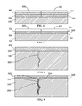
- FIG. 6 is a sectioned view of a substrate, with a slurry layer having a first region and a second region, and at least one covering layer applied thereto, according to an embodiment of the present disclosure.
- FIG. 7 is a sectioned view of the substrate of FIG. 6 after formation of a diffusion coating on the substrate, according to an embodiment of the present disclosure.
- FIG. 8 is a sectioned view of a substrate having a crack, with a slurry layer and at least one covering layer applied thereto, according to an embodiment of the present disclosure.
- FIG. 9 is a sectioned view of the substrate of FIG. 8 after formation of a diffusion coating on the substrate, according to an embodiment of the present disclosure.
- Embodiments of the present disclosure in comparison to processes not utilizing one or more features disclosed herein, decrease costs, increase process efficiency, increase operating lifetime, increase coating uniformity, increase crack coating penetration, add diffusion coating around cracks to prevent crack propagation, ensure a uniform coating, or a combination thereof.
- a process for forming a diffusion coating 500 on a substrate 100 is disclosed.
- the diffusion coating 500 may be any suitable diffusion coating, including, but not limited to, an aluminide diffusion coating, a chromide diffusion coating, or a combination thereof.
- the process includes preparing a slurry 102 including a donor metal powder, an activator powder, and a binder.
- the slurry 102 is applied to the substrate 100 .
- the slurry 102 is dried on the substrate 100 , forming a slurry layer 200 on the substrate 100 .
- a covering composition 300 is applied over the slurry layer 200 .
- the covering composition 300 is dried, forming at least one covering layer 400 enclosing the slurry layer 200 against the substrate 100 .
- the slurry layer 200 and the at least one covering layer 400 are heated to form the diffusion coating 500 on the substrate 100 , the diffusion coating including an additive layer 502 and an interdiffusion zone 504 disposed between the substrate 100 and the additive layer 502 .
- the at least one covering layer 400 may be removed following the heating of the slurry layer 200 and the at least one covering layer 400 . Any portion of the slurry layer 200 remaining following the heating of the slurry layer 200 and the at least one covering layer 400 may also be removed.
- the heating of the slurry layer 200 and the at least one covering layer 400 may transform the at least one covering layer 400 to residues, in which case the removal of the at least one covering layer 400 may include removal of the residues of the at least one covering layer 400 .
- Applying the covering composition 300 and drying the covering composition 300 to form at least one covering layer 400 may be repeated to form a plurality of covering layers 400 including any suitable number of covering layers 400 .
- the at least one covering layer 400 partially covers the slurry layer 200 . In another embodiment, the at least one covering layer 400 fully covers the slurry layer 200 . In yet another embodiment, the at least one covering layer 400 and the substrate 100 enclose the slurry layer 200 . In a further embodiment, the at least one covering layer 400 and the substrate 100 hermetically enclose the slurry layer 200 .
- Applying the at least one covering layer 400 over the slurry layer 200 may increase the uniformity of the diffusion coating 500 relative to a comparable process lacking the at least one covering layer 400 .
- the diffusion coating 500 has heightened uniformity.
- “heightened uniformity” indicates that the diffusion coating 500 covers the substrate 100 without break throughout the area which was covered by the at least one covering layer 400 , and the thickness of the diffusion coating 500 (including both the additive layer 502 and the interdiffusion zone 504 ) does not vary across the diffusion coating 500 by more than about 50% of the greatest thickness of the diffusion coating 500 .
- the diffusion coating 500 is substantially uniform.
- substantially uniform indicates that the diffusion coating 500 covers the substrate 100 without break throughout the area which was covered by the at least one covering layer 400 , and the thickness of the diffusion coating 500 (including both the additive layer 502 and the interdiffusion zone 504 ) does not vary across the diffusion coating 500 by more than about 25% of the greatest thickness of the diffusion coating 500 .
- the diffusion coating 500 is essentially uniform.
- “essentially uniform” indicates that the diffusion coating 500 covers the substrate 100 without break throughout the area which was covered by the at least one covering layer 400 , and the thickness of the diffusion coating 500 (including both the additive layer 502 and the interdiffusion zone 504 ) does not vary across the diffusion coating 500 by more than about 10% of the greatest thickness of the diffusion coating 500 .
- the diffusion coating 500 is uniform.
- “uniform” indicates that the diffusion coating 500 covers the substrate 100 without break throughout the area which was covered by the at least one covering layer 400 , and the thickness of the diffusion coating 500 (including both the additive layer 502 and the interdiffusion zone 504 ) does not vary across the diffusion coating 500 by more than about 5% of the greatest thickness of the diffusion coating 500 .
- the covering composition 300 may include any suitable additives, including, but not limited to, polymer adhesives, ceramic powders, viscosity thinning agents, or a combination thereof.
- the covering composition 300 includes at least one polymer adhesive and at least one ceramic powder.
- Suitable viscosity thinning agents include, but are not limited to, NH 4 Cl, NH 4 F, NH 4 Br, and combinations thereof.
- Applying the slurry 102 may include any suitable technique, including, but not limited to, spraying, dipping, painting, brushing, and combinations thereof.
- Applying the covering composition 300 may include any suitable technique, including, but not limited to spraying, painting, brushing, dipping, and combinations thereof.
- the substrate 100 may include any suitable material composition, including, but not limited to, an iron-based superalloy, a nickel-based superalloy, a cobalt-based superalloy, or a combination thereof.
- the slurry 102 may be applied directly to the substrate 100 .
- the substrate 100 includes a bond coat.
- the slurry 102 may be applied directly to the bond coat.
- the bond coat may be any suitable material, including, but not limited to a MCrAlY, an aluminide diffusion coating, a chromide diffusion coating, or a combination thereof.
- heating the slurry layer 200 and the at least one covering layer 400 to form the diffusion coating 500 includes heating the slurry layer 200 and the at least one covering layer 400 to a temperature within a range of about 550° C. to about 1250° C., alternatively within a range of about 750° C. to about 1200° C., alternatively within a range of about 815° C. to about 1150° C.
- Heating the slurry layer 200 and the at least one covering layer 400 to form the diffusion coating 500 may include any heating duration, including, but not limited to, a duration of from about 0.5 hours to about 12 hours, alternatively about 2 hours to about 8 hours, alternatively about 4 hours to about 6 hours, alternatively less than about 8 hours, alternatively less than about 6 hours.
- Forming the diffusion coating 500 having the additive layer 502 and the interdiffusion zone 504 may include forming the diffusion coating 500 as an additive coating which adds a metal onto the substrate 100 , the added metal forming the additive layer 502 as well as interdiffusing with the substrate 100 to form the interdiffusion zone 504 between the substrate 100 and the additive layer 502 .
- the process for forming the diffusion coating 500 on the substrate 100 further includes a pre-coating cleaning prior to applying the slurry 102 .
- the process for forming the diffusion coating 500 includes a post-coating cleaning while removing the at least one covering layer 400 from the diffusion coating 500 or after removing the at least one covering layer 400 from the diffusion coating 500 .
- the post-coating cleaning may include any suitable technique, and may remove the at least one covering layer 400 , residues of the at least one covering layer 400 remaining following the heating of the at least one covering layer 400 and the slurry layer 200 , the covering composition 300 , the slurry layer 200 , the slurry 102 , impurities, or a combination thereof.
- the suitable technique for cleaning may include, but is not limited to, ultrasonic cleaning in a solvent bath (e.g., water and a suitable reagent), water flushing, grit blasting, or a combination thereof.
- the substrate may be any suitable substrate, including, but not limited to turbine components.
- Suitable turbine components include, but are not limited to buckets (blades), nozzles (vanes), shrouds, diaphragms, combustors, hot gas path components, or combinations thereof.
- the slurry 102 is an aluminizing slurry
- the donor metal powder includes a metallic aluminum alloy having a melting temperature higher than aluminum (melting point of about 660° C.)
- the binder includes at least one organic polymer gel
- the diffusion coating 500 formed is an aluminide diffusion coating including an aluminide additive layer as the additive layer 502 and an aluminide interdiffusion zone as the interdiffusion zone 504 .
- the aluminizing slurry may include any suitable composition, including, but not limited to, a composition having, by weight, about 35% to about 65% of the donor metal powder, about 1% to about 50% of the activator powder, and about 25% to about 60% of the binder.
- the donor metal powder of the aluminizing slurry form of the slurry 102 includes metallic aluminum alloyed with chromium, iron, another aluminum alloying agent, or a combination thereof, provided that the alloying agent does not deposit during the diffusion aluminizing process, but instead serves as an inert carrier for the aluminum of the donor material.
- the donor metal powder includes a chromium-aluminum alloy such as, but not limited to, by weight, about 10% to about 60% aluminum, balance chromium and incidental impurities.
- the donor metal powder has a particle size of up to 100 mesh (149 ⁇ m), alternatively up to ⁇ 200 mesh (74 ⁇ m). Without being bound by theory, it is believed that the donor metal powder being a fine powder reduces the likelihood that the donor metal powder will be lodged or entrapped within the substrate 100 .
- the activator powder of the aluminizing slurry form of the slurry 102 may include any suitable material, including, but not limited to, ammonium chloride, ammonium fluoride, ammonium bromide, another halide activator or combinations thereof. Suitable materials for the activator powder react with aluminum in the donor metal powder to form a volatile aluminum halide, such as, but not limited to, AlCl 3 or AlF 3 , which reacts at the substrate 100 to deposit aluminum, which diffuses into the substrate 100 .
- a volatile aluminum halide such as, but not limited to, AlCl 3 or AlF 3
- the at least one organic polymer gel of the binder of the aluminizing slurry form of the slurry 102 may include, but is not limited to, a polymeric gel available under the name Vitta Braz-Binder Gel from the Vitta Corporation, and low molecular weight polyols such as polyvinyl alcohol.
- the binder further includes a cure catalyst, an accelerant, or both, such as, but not limited to, sodium hypophosphite.
- the aluminizing slurry 102 form of the slurry 102 is free of inert fillers and inorganic binders.
- the absence of inert fillers and inorganic binders prevents such materials from sintering and becoming entrapped in the substrate 100 .
- the aluminizing slurry form of the slurry 102 may further include, by weight, about 1% to about 30% ceramic powder, about 1% to about 10% oxide removal agent, or a combination thereof.
- the ceramic powder may include any suitable material, including, but not limited to, aluminum oxide, chromium oxide, yttrium oxide, zirconium oxide, or a combination thereof.
- the oxide removal agent may include any suitable material, including, but not limited to, an acid such as acetic acid, hydrochloric acid, acids having acidities between acetic acid and hydrochloric acid, inclusive, or a combination thereof.
- the slurry 102 is a chromizing slurry, and the donor metal powder includes chromium.
- the chromizing slurry form of the slurry 102 further includes an inorganic salt having a melting point that is less than or equal to about 800° C.
- the diffusion coating 500 formed is a chromide diffusion coating including a chromide additive layer as the additive layer 502 and a chromide interdiffusion zone as the interdiffusion zone 504 .
- the chromizing slurry may include any suitable composition, including, but not limited to, a composition having, by weight, about 1% to about 60% of the donor metal powder, about 1% to about 70% of the inorganic salt, about 1% to about 30% of the activator powder, and at least about 1% of the binder.
- the chromizing slurry form of the slurry 102 includes a donor metal powder, an inorganic salt having a melting point that is less than or equal to about 800° C., an activator, and a binder, wherein the donor metal powder includes chromium.
- the donor metal powder may include chromium in the form for chromium powder, and may further include an aluminum powder.
- the chromium powder includes an additive such as aluminum, cobalt, nickel, silicon, or mixtures thereof.
- the chromizing slurry form of the slurry 102 includes donor metal powder particles having any suitable size, including, but not limited to, particles having a mean diameter of about 1 to about 10 microns (i.e., micrometers ( ⁇ m)) as measured using a conventional particle size analyzer.
- the activator of the chromizing slurry form of the slurry 102 may be any suitable activator, including, but not limited to, ammonium halides, chromium halides, aluminum halides, and mixtures thereof.
- the activator is NH 4 Cl, NH 4 F, NH 4 Br, CrCl 2 , CrCl 3 , AlCl 3 , or a combination thereof.
- the binder of the chromizing slurry form of the slurry 102 may be any suitable binder which promotes cohesiveness of the chromizing slurry form of the slurry 102 and which decomposes when exposed to a predetermined temperature.
- the slurry layer 102 includes a first region 600 and a second region 602 .
- the first region 600 may be adjacent to or remote from the second region 602 .
- the first region 600 and the second region 602 may be formed from slurries 102 having the same composition or different compositions.
- the first region 600 is an aluminizing slurry layer form of the slurry layer 200 (formed from an aluminizing slurry) and the second region 602 is a chromizing slurry layer form of the slurry layer 200 (formed from a chromizing slurry).
- the first region 600 remains distinct from the second region 602 during and after the formation of the diffusion coating 500 such that the diffusion coating 500 , additive layer 502 , and interdiffusion zone 504 retain the first region 600 and the second region 602 .
- the slurry layer 102 and the diffusion coating 500 may include a third or any number of additional regions.
- the first region 600 includes cracks (not shown) suitable for treatment with an aluminizing slurry, and the first region is 600 is an aluminizing slurry layer form of the slurry layer 200 .
- the second region 600 includes cracks (not shown) suitable for treatment with a chromizing slurry, and the second region is 602 is a chromizing slurry layer form of the slurry layer 200 .
- the first region 600 includes cracks (not shown) suitable for treatment with an aluminizing slurry, and the first region is 600 is an aluminizing slurry layer form of the slurry layer 200
- the second region 600 includes cracks (not shown) suitable for treatment with a chromizing slurry
- the second region is 602 is a chromizing slurry layer form of the slurry layer 200 .
- Tailoring diffusion treatment of cracks based on the exposed internal composition of the cracks in different regions of the substrate 100 may improve diffusion treatment of the cracks, particularly, for example, if the exposed internal compositions of the cracks are different than other portions of the substrate 100 to which diffusion treatments are being applied.
- the substrate 100 includes a crack 800 , and applying the at least one covering layer 400 over the slurry layer 200 adjacent to the crack 800 increases formation of the diffusion coating 500 within the crack relative to a comparable process lacking the at least one covering layer 400 .
- the at least one covering layer 400 may reduce propagation of the crack 800 relative to the comparable process lacking the at least one covering layer 400 .
- the crack 800 may penetrate through less than a thickness of the substrate 100 or may penetrate through the entire thickness of the substrate 100 .
- the slurry layer 200 covers the opening of the crack 800 , and during the heating of the slurry layer 200 and the at least one covering layer 400 , at least a portion of the binder in the slurry layer 200 burns off, and at least a portion of the activator in the slurry layer vaporizes and reacts with the metallic donor of the donor metal powder to form a halide vapor which reacts at the crack surface within the crack 800 to deposit metal (e.g., aluminum or chromium) on the crack surfaces, and diffuse the deposited metal into the crack surfaces to form a diffusion metal coating.
- metal e.g., aluminum or chromium
- the presence of the at least one covering layer 400 enhances the penetration of the halide vapor into the crack 800 , and promotes the formation of the metal diffusion coatings on both sides of the crack 800 , growing the metal diffusion coating from both sides of the crack 800 to heal the crack 800 when the metal diffusion coatings from both sides join together.
- it is the additive layer 502 which grows outward during the heating of the slurry layer 200 and the at least one covering layer 400 to heal the crack 800 .
Landscapes
- Chemical & Material Sciences (AREA)
- Engineering & Computer Science (AREA)
- Mechanical Engineering (AREA)
- Materials Engineering (AREA)
- Chemical Kinetics & Catalysis (AREA)
- Metallurgy (AREA)
- Organic Chemistry (AREA)
- General Engineering & Computer Science (AREA)
- Inorganic Chemistry (AREA)
- Other Surface Treatments For Metallic Materials (AREA)
- Turbine Rotor Nozzle Sealing (AREA)
- Application Of Or Painting With Fluid Materials (AREA)
Abstract
Description
Claims (20)
Priority Applications (3)
| Application Number | Priority Date | Filing Date | Title |
|---|---|---|---|
| US15/264,313 US10077494B2 (en) | 2016-09-13 | 2016-09-13 | Process for forming diffusion coating on substrate |
| JP2017168111A JP7019349B2 (en) | 2016-09-13 | 2017-09-01 | Process for forming a diffusion coating on a substrate |
| EP17189764.8A EP3293281A1 (en) | 2016-09-13 | 2017-09-07 | Process for forming diffusion coating on substrate |
Applications Claiming Priority (1)
| Application Number | Priority Date | Filing Date | Title |
|---|---|---|---|
| US15/264,313 US10077494B2 (en) | 2016-09-13 | 2016-09-13 | Process for forming diffusion coating on substrate |
Publications (2)
| Publication Number | Publication Date |
|---|---|
| US20180073123A1 US20180073123A1 (en) | 2018-03-15 |
| US10077494B2 true US10077494B2 (en) | 2018-09-18 |
Family
ID=59974124
Family Applications (1)
| Application Number | Title | Priority Date | Filing Date |
|---|---|---|---|
| US15/264,313 Active US10077494B2 (en) | 2016-09-13 | 2016-09-13 | Process for forming diffusion coating on substrate |
Country Status (3)
| Country | Link |
|---|---|
| US (1) | US10077494B2 (en) |
| EP (1) | EP3293281A1 (en) |
| JP (1) | JP7019349B2 (en) |
Cited By (1)
| Publication number | Priority date | Publication date | Assignee | Title |
|---|---|---|---|---|
| US20210054744A1 (en) * | 2019-08-23 | 2021-02-25 | United Technologies Corporation | Slurry based diffusion coatings for blade under platform of internally-cooled components and process therefor |
Families Citing this family (2)
| Publication number | Priority date | Publication date | Assignee | Title |
|---|---|---|---|---|
| US10378094B2 (en) | 2009-05-21 | 2019-08-13 | Battelle Memorial Institute | Reactive coating processes |
| US10577694B2 (en) * | 2009-05-21 | 2020-03-03 | Battelle Memorial Institute | Protective aluminum oxide surface coatings and low-temperature forming process for high-temperature applications |
Citations (44)
| Publication number | Priority date | Publication date | Assignee | Title |
|---|---|---|---|---|
| US2685543A (en) | 1951-01-17 | 1954-08-03 | Wearex Corp | Production of chromium carbide surfaced wear resistant ferrous bodies |
| US3741791A (en) | 1971-08-05 | 1973-06-26 | United Aircraft Corp | Slurry coating superalloys with fecraiy coatings |
| US3867266A (en) | 1971-05-14 | 1975-02-18 | Nippon Kokan Kk | Method of plating aluminum-chromium alloys |
| US3903338A (en) | 1971-07-02 | 1975-09-02 | Alloy Surfaces Co Inc | Continuous diffusion coating |
| USRE29212E (en) | 1973-01-31 | 1977-05-10 | Alloy Surfaces Company, Inc. | Pack diffusion coating of metals |
| JPS5696067A (en) | 1979-09-07 | 1981-08-03 | Alloy Surfaces Co Inc | Diffusion coating through limited part |
| US4617202A (en) * | 1970-11-18 | 1986-10-14 | Alloy Surfaces Company, Inc. | Diffusion coating mixtures |
| JPS63190158A (en) | 1986-11-03 | 1988-08-05 | ユナイテッド・テクノロジーズ・コーポレイション | Method for forming aluminite coating |
| US5366765A (en) | 1993-05-17 | 1994-11-22 | United Technologies Corporation | Aqueous slurry coating system for aluminide coatings |
| US6022632A (en) | 1996-10-18 | 2000-02-08 | United Technologies | Low activity localized aluminide coating |
| US6110262A (en) | 1998-08-31 | 2000-08-29 | Sermatech International, Inc. | Slurry compositions for diffusion coatings |
| US6296705B1 (en) | 1999-12-15 | 2001-10-02 | United Technologies Corporation | Masking fixture and method |
| US6395406B1 (en) * | 2000-04-24 | 2002-05-28 | General Electric Company | Methods for preparing and applying coatings on metal-based substrates, and related compositions and articles |
| JP2003183809A (en) | 2001-08-31 | 2003-07-03 | Sermatech Internatl Inc | Method for forming local aluminide cover |
| US6706325B2 (en) | 2000-04-11 | 2004-03-16 | General Electric Company | Article protected by a thermal barrier coating system and its fabrication |
| US20040115355A1 (en) | 2002-12-13 | 2004-06-17 | Bauer Steven Earl | Method for coating an internal surface of an article with an aluminum-containing coating |
| GB2401117A (en) * | 2003-05-01 | 2004-11-03 | Rolls Royce Plc | A method of preventing aluminising and a mask to prevent aluminising |
| US20050014010A1 (en) | 2003-04-22 | 2005-01-20 | Dumm Timothy Francis | Method to provide wear-resistant coating and related coated articles |
| US20050031877A1 (en) | 2003-08-04 | 2005-02-10 | Gigliotti Michael Francis X. | Organic coating compositions for aluminizing metal substrates, and related methods and articles |
| US20060141283A1 (en) | 2004-12-29 | 2006-06-29 | Honeywell International, Inc. | Low cost inovative diffused MCrAIY coatings |
| JP2006199988A (en) | 2005-01-19 | 2006-08-03 | Ishikawajima Harima Heavy Ind Co Ltd | Local execution method of diffusion aluminide coating |
| US7150926B2 (en) | 2003-07-16 | 2006-12-19 | Honeywell International, Inc. | Thermal barrier coating with stabilized compliant microstructure |
| US20090126833A1 (en) * | 2007-11-15 | 2009-05-21 | General Electric Company | Slurry diffusion aluminide coating composition and process |
| US20090169750A1 (en) * | 2007-12-27 | 2009-07-02 | Melvin Howard Wilkins | Methods for Improving Corrosion and Oxidation Resistance to the Under Platform Region of a Gas Turbine Blade |
| US7597966B2 (en) | 2005-06-10 | 2009-10-06 | General Electric Company | Thermal barrier coating and process therefor |
| US20100151125A1 (en) | 2003-08-04 | 2010-06-17 | General Electric Company | Slurry chromizing process |
| US20110058591A1 (en) | 2009-09-07 | 2011-03-10 | Electronics And Telecommunications Research Institute | Frequency selective modulating apparatus and method using re-spreading code |
| US20110058952A1 (en) | 2009-09-08 | 2011-03-10 | Mtu Aero Engines Gmbh | High-temperature anti-corrosive layer and method for the production thereof |
| US8124426B2 (en) | 2010-01-06 | 2012-02-28 | International Business Machines Corporation | Tunnel junction via |
| US20120060721A1 (en) | 2003-08-04 | 2012-03-15 | General Electric Company | Slurry chromizing compositions |
| US20120094021A1 (en) * | 2010-10-13 | 2012-04-19 | Goodrich Corporation | Method of forming a diffusion aluminide coating on a surface of a turbine component and a homogeneous paste for coating such surfaces |
| US8262812B2 (en) | 2007-04-04 | 2012-09-11 | General Electric Company | Process for forming a chromium diffusion portion and articles made therefrom |
| US20120324902A1 (en) | 2011-06-27 | 2012-12-27 | General Electric Company | Method of maintaining surface-related properties of gas turbine combustor components |
| US20130004712A1 (en) | 2011-06-13 | 2013-01-03 | Irina Belov | Multilayer overlay system for thermal and corrosion protection of superalloy substrates |
| US20130175325A1 (en) | 2012-01-05 | 2013-07-11 | General Electric Company | Method for making a cellular seal |
| US8596985B2 (en) | 2006-06-24 | 2013-12-03 | Siemens Aktiengesellschaft | Method of protecting a component against hot corrosion and a component protected by said method |
| US20140044986A1 (en) | 2012-08-08 | 2014-02-13 | MTU Aero Engines AG | DUPLEX-PHASE CrAl COATING FOR IMPROVED CORROSION/OXIDATION PROTECTION |
| US20140044938A1 (en) | 2012-08-10 | 2014-02-13 | MTU Aero Engines AG | Process for producing a COMPONENT-MATCHED PROTECTIVE LAYER and component having such a protective layer |
| US8741381B2 (en) | 2012-05-04 | 2014-06-03 | General Electric Company | Method for removing a coating and a method for rejuvenating a coated superalloy component |
| JP5696067B2 (en) | 2012-02-22 | 2015-04-08 | 株式会社日立産機システム | Programmable controller |
| US20150144496A1 (en) * | 2013-11-26 | 2015-05-28 | Honeywell International Inc. | Methods and systems for manufacturing components from articles formed by additive-manufacturing processes |
| US20150197841A1 (en) * | 2014-01-14 | 2015-07-16 | Zhihong Tang | Methods of applying chromium diffusion coatings onto selective regions of a component |
| US20160010472A1 (en) * | 2012-02-21 | 2016-01-14 | Howment Corporation | Coating and coating method for gas turbine engine component |
| US20160230284A1 (en) * | 2015-02-10 | 2016-08-11 | Arcanum Alloy Design, Inc. | Methods and systems for slurry coating |
Family Cites Families (2)
| Publication number | Priority date | Publication date | Assignee | Title |
|---|---|---|---|---|
| US7270852B2 (en) * | 2003-08-04 | 2007-09-18 | General Electric Company | Aluminizing slurry compositions free of hexavalent chromium, and related methods and articles |
| CN102851634B (en) * | 2012-09-11 | 2015-01-21 | 中国科学院金属研究所 | Environment-friendly chromium-ion-free aqueous phosphate-based silicon-aluminizing slurry |
-
2016
- 2016-09-13 US US15/264,313 patent/US10077494B2/en active Active
-
2017
- 2017-09-01 JP JP2017168111A patent/JP7019349B2/en active Active
- 2017-09-07 EP EP17189764.8A patent/EP3293281A1/en not_active Withdrawn
Patent Citations (50)
| Publication number | Priority date | Publication date | Assignee | Title |
|---|---|---|---|---|
| US2685543A (en) | 1951-01-17 | 1954-08-03 | Wearex Corp | Production of chromium carbide surfaced wear resistant ferrous bodies |
| US4617202A (en) * | 1970-11-18 | 1986-10-14 | Alloy Surfaces Company, Inc. | Diffusion coating mixtures |
| US3867266A (en) | 1971-05-14 | 1975-02-18 | Nippon Kokan Kk | Method of plating aluminum-chromium alloys |
| US3903338A (en) | 1971-07-02 | 1975-09-02 | Alloy Surfaces Co Inc | Continuous diffusion coating |
| US3741791A (en) | 1971-08-05 | 1973-06-26 | United Aircraft Corp | Slurry coating superalloys with fecraiy coatings |
| USRE29212E (en) | 1973-01-31 | 1977-05-10 | Alloy Surfaces Company, Inc. | Pack diffusion coating of metals |
| JPS5696067A (en) | 1979-09-07 | 1981-08-03 | Alloy Surfaces Co Inc | Diffusion coating through limited part |
| JPS63190158A (en) | 1986-11-03 | 1988-08-05 | ユナイテッド・テクノロジーズ・コーポレイション | Method for forming aluminite coating |
| US5217757A (en) | 1986-11-03 | 1993-06-08 | United Technologies Corporation | Method for applying aluminide coatings to superalloys |
| US5366765A (en) | 1993-05-17 | 1994-11-22 | United Technologies Corporation | Aqueous slurry coating system for aluminide coatings |
| US6022632A (en) | 1996-10-18 | 2000-02-08 | United Technologies | Low activity localized aluminide coating |
| US6444054B1 (en) | 1998-08-31 | 2002-09-03 | Sermatech International, Inc. | Slurry compositions for diffusion coatings |
| US6110262A (en) | 1998-08-31 | 2000-08-29 | Sermatech International, Inc. | Slurry compositions for diffusion coatings |
| US6296705B1 (en) | 1999-12-15 | 2001-10-02 | United Technologies Corporation | Masking fixture and method |
| US6706325B2 (en) | 2000-04-11 | 2004-03-16 | General Electric Company | Article protected by a thermal barrier coating system and its fabrication |
| US6395406B1 (en) * | 2000-04-24 | 2002-05-28 | General Electric Company | Methods for preparing and applying coatings on metal-based substrates, and related compositions and articles |
| JP2003183809A (en) | 2001-08-31 | 2003-07-03 | Sermatech Internatl Inc | Method for forming local aluminide cover |
| US6730179B2 (en) | 2001-08-31 | 2004-05-04 | Sermatech International Inc. | Method for producing local aluminide coating |
| US20040115355A1 (en) | 2002-12-13 | 2004-06-17 | Bauer Steven Earl | Method for coating an internal surface of an article with an aluminum-containing coating |
| US20050014010A1 (en) | 2003-04-22 | 2005-01-20 | Dumm Timothy Francis | Method to provide wear-resistant coating and related coated articles |
| GB2401117A (en) * | 2003-05-01 | 2004-11-03 | Rolls Royce Plc | A method of preventing aluminising and a mask to prevent aluminising |
| US7150926B2 (en) | 2003-07-16 | 2006-12-19 | Honeywell International, Inc. | Thermal barrier coating with stabilized compliant microstructure |
| US20050031877A1 (en) | 2003-08-04 | 2005-02-10 | Gigliotti Michael Francis X. | Organic coating compositions for aluminizing metal substrates, and related methods and articles |
| US20100151125A1 (en) | 2003-08-04 | 2010-06-17 | General Electric Company | Slurry chromizing process |
| US20120060721A1 (en) | 2003-08-04 | 2012-03-15 | General Electric Company | Slurry chromizing compositions |
| US20060141283A1 (en) | 2004-12-29 | 2006-06-29 | Honeywell International, Inc. | Low cost inovative diffused MCrAIY coatings |
| JP2006199988A (en) | 2005-01-19 | 2006-08-03 | Ishikawajima Harima Heavy Ind Co Ltd | Local execution method of diffusion aluminide coating |
| US20070009660A1 (en) | 2005-01-19 | 2007-01-11 | Akiko Sasaki | Method for local application of diffusion aluminide coating |
| US7597966B2 (en) | 2005-06-10 | 2009-10-06 | General Electric Company | Thermal barrier coating and process therefor |
| US8596985B2 (en) | 2006-06-24 | 2013-12-03 | Siemens Aktiengesellschaft | Method of protecting a component against hot corrosion and a component protected by said method |
| US8262812B2 (en) | 2007-04-04 | 2012-09-11 | General Electric Company | Process for forming a chromium diffusion portion and articles made therefrom |
| US20090126833A1 (en) * | 2007-11-15 | 2009-05-21 | General Electric Company | Slurry diffusion aluminide coating composition and process |
| US8916005B2 (en) | 2007-11-15 | 2014-12-23 | General Electric Company | Slurry diffusion aluminide coating composition and process |
| US20090169750A1 (en) * | 2007-12-27 | 2009-07-02 | Melvin Howard Wilkins | Methods for Improving Corrosion and Oxidation Resistance to the Under Platform Region of a Gas Turbine Blade |
| US20110058591A1 (en) | 2009-09-07 | 2011-03-10 | Electronics And Telecommunications Research Institute | Frequency selective modulating apparatus and method using re-spreading code |
| US20110058952A1 (en) | 2009-09-08 | 2011-03-10 | Mtu Aero Engines Gmbh | High-temperature anti-corrosive layer and method for the production thereof |
| US8124426B2 (en) | 2010-01-06 | 2012-02-28 | International Business Machines Corporation | Tunnel junction via |
| US20120094021A1 (en) * | 2010-10-13 | 2012-04-19 | Goodrich Corporation | Method of forming a diffusion aluminide coating on a surface of a turbine component and a homogeneous paste for coating such surfaces |
| US20130004712A1 (en) | 2011-06-13 | 2013-01-03 | Irina Belov | Multilayer overlay system for thermal and corrosion protection of superalloy substrates |
| US20120324902A1 (en) | 2011-06-27 | 2012-12-27 | General Electric Company | Method of maintaining surface-related properties of gas turbine combustor components |
| US20130175325A1 (en) | 2012-01-05 | 2013-07-11 | General Electric Company | Method for making a cellular seal |
| US8973808B2 (en) | 2012-01-05 | 2015-03-10 | General Electric Company | Method for making a cellular seal |
| US20160010472A1 (en) * | 2012-02-21 | 2016-01-14 | Howment Corporation | Coating and coating method for gas turbine engine component |
| JP5696067B2 (en) | 2012-02-22 | 2015-04-08 | 株式会社日立産機システム | Programmable controller |
| US8741381B2 (en) | 2012-05-04 | 2014-06-03 | General Electric Company | Method for removing a coating and a method for rejuvenating a coated superalloy component |
| US20140044986A1 (en) | 2012-08-08 | 2014-02-13 | MTU Aero Engines AG | DUPLEX-PHASE CrAl COATING FOR IMPROVED CORROSION/OXIDATION PROTECTION |
| US20140044938A1 (en) | 2012-08-10 | 2014-02-13 | MTU Aero Engines AG | Process for producing a COMPONENT-MATCHED PROTECTIVE LAYER and component having such a protective layer |
| US20150144496A1 (en) * | 2013-11-26 | 2015-05-28 | Honeywell International Inc. | Methods and systems for manufacturing components from articles formed by additive-manufacturing processes |
| US20150197841A1 (en) * | 2014-01-14 | 2015-07-16 | Zhihong Tang | Methods of applying chromium diffusion coatings onto selective regions of a component |
| US20160230284A1 (en) * | 2015-02-10 | 2016-08-11 | Arcanum Alloy Design, Inc. | Methods and systems for slurry coating |
Non-Patent Citations (14)
| Title |
|---|
| APV Engineered Coatings, Safety Data Sheet for S-0099-01, date prepared Sep. 17, 2015, pp. 1-8, Akron. |
| Cao, et al.; "A Novel Duplex Low-temperature Chromizing Process at 500 degrees C.," J. Mater Sci. Technol., vol. 23, No. 6, 2007, pp. 823-827. |
| Cao, et al.; Phase transformations in low-temperature chromized 0.45 wt. per cent C plain carbon steel, Surface and Coatings Technology, vol. 201, 2007, pp. 7970-7977. |
| Extended European Search Report and Opinion issued in connection with corresponding EP Application No. 17189764.8 dated Nov. 7, 2017. |
| G.W. Goward; "Progress in coatings for gas turbine airfoils," Surface and Coatings Technology, Oct. 10, 1998, vols. 108-109, pp. 73-79. |
| Harada and Negoro. Inner Diffusion Behavior of Chromium Diffusion Coating Layer Studies on Chromium Diffusion Coating of Nickel Superalloys (1973)(Part 7). (Year: 1973). * |
| Huiliang et al. A Novel Duplex Low-temperature Chromizing Process at 500° C. Journal of Material Science Technology vol. 23 No. 6 (2007) (Year: 2007). * |
| Kool, et al.; "Chromide Coatings, Articles Coated with Chromide Coatings, and Processes for Forming Chromide Coatings," filed Dec. 30, 2014 as U.S. Appl. No. 14/585,890 (not yet published). |
| Leferink, et al.; "Chromium Diffusion Coatings on Low-Alloyed Steels for Corrosion Protection Under Sulphidizing Conditions," VGB Kraftwerkstechnik, vol. 73, No. 3, 1993, pp. 1-14. |
| Sikalidis, ed., Advances in Ceramics-Synthesis and Characterization, Processing and Specific Applications, Chapter 4 by Kimura entitled "Molten Salt Synthesis of Ceramic Powders", Aug. 2001, pp. 75-100. |
| Sikalidis, ed., Advances in Ceramics—Synthesis and Characterization, Processing and Specific Applications, Chapter 4 by Kimura entitled "Molten Salt Synthesis of Ceramic Powders", Aug. 2001, pp. 75-100. |
| Wang, et al.; "Diffusion Coatings for Metal-Based Substrate and Methods of Preparation Thereof", filed Jun. 24, 2015 as U.S. Appl. No. 14/749,096 (not yet published). |
| Zhang, et al.; "Coating Process for Applying a Bifurcated Coating", filed Jun. 22, 2016 as U.S. Appl. No. 15/189,854 (not yet published). |
| Zhu, et al.; "Oxidation of a Novel Chromium Coating with CeO2 Dispersions," Oxidation of Metals, Dec. 2004, vol. 62, Issue 516, pp. 411-426. |
Cited By (2)
| Publication number | Priority date | Publication date | Assignee | Title |
|---|---|---|---|---|
| US20210054744A1 (en) * | 2019-08-23 | 2021-02-25 | United Technologies Corporation | Slurry based diffusion coatings for blade under platform of internally-cooled components and process therefor |
| US11970953B2 (en) * | 2019-08-23 | 2024-04-30 | Rtx Corporation | Slurry based diffusion coatings for blade under platform of internally-cooled components and process therefor |
Also Published As
| Publication number | Publication date |
|---|---|
| JP7019349B2 (en) | 2022-02-15 |
| JP2018076586A (en) | 2018-05-17 |
| EP3293281A1 (en) | 2018-03-14 |
| US20180073123A1 (en) | 2018-03-15 |
Similar Documents
| Publication | Publication Date | Title |
|---|---|---|
| JP5698896B2 (en) | Slurry diffusion aluminide coating method | |
| JP4549490B2 (en) | Method for simultaneously aluminizing nickel-base and cobalt-base superalloys | |
| US8973808B2 (en) | Method for making a cellular seal | |
| US6485780B1 (en) | Method for applying coatings on substrates | |
| CN105899707B (en) | Method for applying chromium diffusion coatings on selected regions of a component | |
| US8318251B2 (en) | Method for coating honeycomb seal using a slurry containing aluminum | |
| US10077494B2 (en) | Process for forming diffusion coating on substrate | |
| US7390534B2 (en) | Diffusion coating process | |
| EP2886677B1 (en) | A slurry and a coating method | |
| US20220213585A1 (en) | Aluminum-chromium diffusion coating | |
| JP2001064763A (en) | Method for controlling thickness and aluminum content of diffused aluminide film | |
| US20050191421A1 (en) | Method for coating a component | |
| KR102146700B1 (en) | Slurry formulation for formation of reactive element-doped aluminide coating and method of forming same | |
| EP3144409A1 (en) | Thermal barrier coating system and processes for forming a thermal barrier coating system | |
| EP3475459B1 (en) | Coating process for applying a bifurcated coating | |
| JP2019534375A5 (en) | ||
| US20180087141A1 (en) | Method for treating coated article and treated article |
Legal Events
| Date | Code | Title | Description |
|---|---|---|---|
| AS | Assignment |
Owner name: GENERAL ELECTRIC COMPANY, NEW YORK Free format text: ASSIGNMENT OF ASSIGNORS INTEREST;ASSIGNORS:LIN, DECHAO;BUCCI, DAVID VINCENT;LIU, SHAN;AND OTHERS;SIGNING DATES FROM 20160909 TO 20160912;REEL/FRAME:039738/0212 |
|
| STCF | Information on status: patent grant |
Free format text: PATENTED CASE |
|
| MAFP | Maintenance fee payment |
Free format text: PAYMENT OF MAINTENANCE FEE, 4TH YEAR, LARGE ENTITY (ORIGINAL EVENT CODE: M1551); ENTITY STATUS OF PATENT OWNER: LARGE ENTITY Year of fee payment: 4 |
|
| AS | Assignment |
Owner name: GE INFRASTRUCTURE TECHNOLOGY LLC, SOUTH CAROLINA Free format text: ASSIGNMENT OF ASSIGNORS INTEREST;ASSIGNOR:GENERAL ELECTRIC COMPANY;REEL/FRAME:065727/0001 Effective date: 20231110 |