EP1301419B1 - Verpackung für haushaltsgeräte mit umverpackungsfilm zum anheben unter dem verpackungsdeckel - Google Patents
Verpackung für haushaltsgeräte mit umverpackungsfilm zum anheben unter dem verpackungsdeckel Download PDFInfo
- Publication number
- EP1301419B1 EP1301419B1 EP01952650A EP01952650A EP1301419B1 EP 1301419 B1 EP1301419 B1 EP 1301419B1 EP 01952650 A EP01952650 A EP 01952650A EP 01952650 A EP01952650 A EP 01952650A EP 1301419 B1 EP1301419 B1 EP 1301419B1
- Authority
- EP
- European Patent Office
- Prior art keywords
- basiloid
- top cap
- appliance
- corner posts
- glued
- Prior art date
- Legal status (The legal status is an assumption and is not a legal conclusion. Google has not performed a legal analysis and makes no representation as to the accuracy of the status listed.)
- Expired - Lifetime
Links
Images


Classifications
-
- B—PERFORMING OPERATIONS; TRANSPORTING
- B65—CONVEYING; PACKING; STORING; HANDLING THIN OR FILAMENTARY MATERIAL
- B65D—CONTAINERS FOR STORAGE OR TRANSPORT OF ARTICLES OR MATERIALS, e.g. BAGS, BARRELS, BOTTLES, BOXES, CANS, CARTONS, CRATES, DRUMS, JARS, TANKS, HOPPERS, FORWARDING CONTAINERS; ACCESSORIES, CLOSURES, OR FITTINGS THEREFOR; PACKAGING ELEMENTS; PACKAGES
- B65D85/00—Containers, packaging elements or packages, specially adapted for particular articles or materials
- B65D85/68—Containers, packaging elements or packages, specially adapted for particular articles or materials for machines, engines or vehicles in assembled or dismantled form
-
- B—PERFORMING OPERATIONS; TRANSPORTING
- B65—CONVEYING; PACKING; STORING; HANDLING THIN OR FILAMENTARY MATERIAL
- B65D—CONTAINERS FOR STORAGE OR TRANSPORT OF ARTICLES OR MATERIALS, e.g. BAGS, BARRELS, BOTTLES, BOXES, CANS, CARTONS, CRATES, DRUMS, JARS, TANKS, HOPPERS, FORWARDING CONTAINERS; ACCESSORIES, CLOSURES, OR FITTINGS THEREFOR; PACKAGING ELEMENTS; PACKAGES
- B65D2585/00—Containers, packaging elements or packages specially adapted for particular articles or materials
- B65D2585/68—Containers, packaging elements or packages specially adapted for particular articles or materials for machines, engines, or vehicles in assembled or dismantled form
- B65D2585/6802—Containers, packaging elements or packages specially adapted for particular articles or materials for machines, engines, or vehicles in assembled or dismantled form specific machines, engines or vehicles
- B65D2585/6845—Containers, packaging elements or packages specially adapted for particular articles or materials for machines, engines, or vehicles in assembled or dismantled form specific machines, engines or vehicles other household devices
- B65D2585/6855—Containers, packaging elements or packages specially adapted for particular articles or materials for machines, engines, or vehicles in assembled or dismantled form specific machines, engines or vehicles other household devices washing machine
Definitions
- This patent relates to packaging for large appliances. More particularly, this patent relates to a Clearview packaging assembly for basiloid handling of appliances with irregular top surfaces.
- See-through containers for large appliances have been proposed in U.S. Patents Nos. 3,891,086, 4;811,840, 5,289,969 and 5,307,928.
- These proposed see-through containers generally comprise top and bottom caps, corner support posts extending between the top and bottom caps, and heavy plastic see-through wrapping.
- the top and bottom caps may be secured to the support posts with horizontal retaining bands, as in U.S. Patent No. 3,891,086, or vertical retaining bands, as in U.S. Patent No. 5,307,928.
- the appliances When packaged in this way the appliances can be moved with standard fork lift trucks or with basiloid lift trucks.
- Basiloid lift trucks lifts an appliance container by the top cap instead of by the bottom of the container.
- Basiloid lift trucks have a vertically oriented lift blade extending from an upper frame that is secured to an elevator mechanism mounted on the front end of the lift truck.
- the vertical blade is placed in flat contact with the side of the packaged appliance.
- the elevator mechanism raises the lift blade, the top edge of the blade extends into the crease between the side of the package and the downwardly extending lip of the top cap.
- the lift blade is raised until a horizontal lifting bar mounted on the blade abuts the bottom edge of the top cap lip.
- the appliance can then be lifted off the floor by the elevator mechanism and moved.
- the lift blade must be slightly shorter than the top cap lip so that the blade does not pierce the top cap.
- the force of the blade lifting at the top of the unit is transferred to the bottom of the unit. No significant force is applied to the front edge of the top cap opposite the basiloid blade.
- the weight of the top unit since it is not all on top of the basiloid flap, tends to shift forward.
- the front edge of the bottom unit top cap deflects downwardly, a phenomenon referred to as trapezoiding.
- the front edge of the bottom unit deflects downwardly, the top unit tips forward and can fall off.
- the front edge of the top cap can deflect up to 15.24 cm (six inches) or more, depending on the vertical space between the front edge of the top cap and the top surface of the irregular shaped appliance.
- One method for preventing trapezoiding of packages containing irregular shaped appliances is to use a standoff made of a resilient material such as expanded polystyrene to take up the space between the top cap and the appliance top surface, thereby transferring the force from the top appliance directly to the top surface of the bottom appliance.
- standoffs waste material and put extra undue force on the bottom of the bottom package.
- a further object of the present invention is to provide a packaging assembly for irregular shaped appliances that resists trapezoiding during basiloid lifting with a second unit on top.
- a still further object of the present invention is to provide a packaging assembly having an integral basiloid flap formed by the cooperation of the top cap and a separate basiloid piece.
- Another object of the present invention is to provide a clamshell-type packaging assembly that can be easily installed over an appliance mounted on a base pad.
- the present invention provides a packaging assembly for an irregular top appliance, said appliance having a top surface and a raised portion extending above the top surface, said packaging assembly comprising a framework having:
- Packaging assemblies in accordance with the present invention are particularly suited for an irregular top appliance, that is, an appliance having a relatively flat top surface and a raised portion extending above the top surface, typically in the rear.
- the packaging assembly comprises a clamshell-like framework that is glued together prior to installing it over the appliance, and a transparent polymer film wrapped tightly around the framework after it has been installed over the appliance.
- the clamshell-like framework is preferably made from a corrugated top cap, front and rear corner posts, two bottom pieces and a basiloid piece.
- the top cap preferably has a large flat top panel, substantially triangular shaped side panels extending downward from opposite sides of the top panel, and a rear flap separated from the top panel by a fold line that functions as the clamshell hinge.
- the two front corner posts are glued to the triangular shaped side panels.
- the lower ends of the two front corner posts are, glued to one of the bottom pieces to form one half of the clamshell.
- the basiloid piece has a rear panel and a basiloid flap separated by a fold line.
- the top cap rear flap and the basiloid flap are glued together to form a basiloid handling flange which facilitates lifting and moving of the packaging assembly with the appliance contained therein by a basiloid fork lift truck.
- the two rear corner posts are glued along their upper ends to the basiloid piece rear panel and along their lower ends to the second bottom piece to form the other half of the clamshell.
- the clamshell framework can be easily installed over an appliance mounted on a base pad.
- the framework and appliance, except for the basiloid flap, is preferably wrapped in a transparent polymer wrapping material, leaving much of the appliance visible.
- the basiloid flap is preferably retained by a horizontal retaining band to from the completed structure.
- the downward force caused by a second unit stacked on top during basiloid lifting can cause the front edge of the bottom unit top cap to deflect downward, a phenomenon referred to as trapezoiding. This deflection can continue until the front edge of the top cap meets the top surface of the bottom appliance, causing the top appliance to tip forward
- the present invention prevents such trapezoiding by providing side panels, which are preferably substantially triangular-shaped, glued to the front corner posts.
- the front corner posts abut the front vertical corners of the appliance.
- the front vertical corners prevent the corner posts and top cap from rotating about the clamshell hinge, thereby preventing the trapezoiding associated with conventional see-through appliance packages.
- the front corner posts serve as an extension of the triangle defined by the top cap sidewalls, and serve to spread the force created by the top unit during basiloid lifting to an area along the entire front vertical edges of the bottom appliance. If the front corner posts are not glued to the top cap, the top cap could slide downward along the front corner posts, resulting in trapezoiding.
- the present invention is a packaging assembly comprising a framework and transparent wrapping.
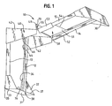
- a framework made according to the present invention.
- the framework 10 is designed for basiloid handling of irregular top appliances, and comprises four structural support members 12, 13, 14 and 15, two bottom pieces 30, a top cap 40 and a basiloid flange piece 50.
- the assembly framework 10 has a two-piece hinged design that installs easily over an appliance 20.
- the appliance is mounted to a base pad 60 that supports the appliance 20 during assembly and handling.
- the base pad 60 may be formed of wood, paper and paperboard, expanded foam, or any other suitable material or combination of materials.
- the base pad may be made from a combination of low and high density materials, such as the type manufactured by Sonoco Products Company under the trademark SonobaseTM, which is the subject of a pending United States patent application.
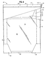
- the packaging assembly framework 10 After installation over an appliance, the packaging assembly framework 10, with the exception of the basiloid handling flange 70 to be described later, is wrapped in transparent plastic film 80 ("Clearview") that allows much of the appliance 20 to be seen ( Figure 6).
- a retaining band 28 is tightly wrapped around the top end of the top cap 40 and the basiloid handling flange 70 to maintain the flange 70 in the proper position during basiloid lifting and handling.
- the final packaging assembly, including the framework 10 and transparent wrapping 80 may be referred to as a Clearview basiloid pack.
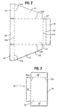
- Figure 2 shows a cardboard blank used to form the top cap 40.
- the blank has a top panel 41 defined by fold lines 42a, 43a, 46a and 47a, the width and depth of the top panel being determined by the dimensions of the appliance to be packaged.
- left and right side panels 42, 43 extend downward from the top panel 41 and are glued to the two front corner posts 12, 13.
- the side panels 42, 43 are cut at an angle so that they are substantially triangular in shape, with their front edges extending farther down than their rear edges.
- the front edges of the side panels 42, 43 extend near or below the plane defined by the top surface 21 of the appliance 20 (see Figures 5 and 6).
- the left side panel 42 is folded along fold line 44a to create a left front flap 44 that is folded at a right angle to the top panel 41 and glued to the left front corner post 12.
- the right side panel 43 is folded at a right angle along fold line 45a to create a right front flap 45 that is then glued to the right front corner post 13.
- a front panel 46 extends downward from the front edge 46a of the top panel 41 and is glued to the upper portions of the left and right front flaps 44, 45.
- a fold line or hinge 47a separates the top panel 41 from a short rear flap 47.
- This hinge 47a allows for the framework's clamshell operation.
- the short rear flap 47 extends downward from the top panel 41 and terminates at upturned edge 49.
- An inner flap 48 which is a continuation of the top panel 40, extends upward from the edge 49 parallel to rear flap 47, defining a space therebetween to accommodate a separate basiloid flap 55 as will now be described.
- FIG 3 is a top view of a blank used to form the basiloid piece 50.
- the blank has a rear panel 51 defined by fold lines 53a, 54a, a lower edge 54 and a down turned edge 55a.
- the basiloid piece 50 preferably extends below the plane defined by the top surface 21 of the appliance 20.
- the basiloid piece 50 forms a three-sided shell around the rear elevated portion 23 of the irregular shaped appliance 20.
- left and right side flaps 52, 53 extend from the rear panel 51 and are glued to the upper portions of the rear left and right corner posts 14, 15 respectively.
- a basiloid flap 55 extends downward between the rear flap 47 and the upturned inner flap 48 of the top cap 40 and is secured therebetween by glue or other adhesive means to form a basiloid handling flange 70.
- a retainer band 28 is wrapped tightly around the upper portion of,the assembly to retain the basiloid handling flange 70.
- the basiloid flange 70 is three layers thick and has a lower edge 49 that bears the lifting force of a basiloid blade.
- the basiloid handling flange 70 preferably extends about 15.24 to 35.56 cm (six to fourteen inches) downward from the top panel 41 and is held in place by the retaining band 28.
- the purpose of the flap 70 is to accommodate the basiloid lifting blade of a basiloid fork lift truck.
- the basiloid blade (not shown) is inserted into the slot 71 between the basiloid flange 70 and the rear panel 51 of the basiloid piece 50.
- the basiloid blade has a rounded top edge so that the forklift operator doesn't inadvertently hook the blade into the plastic film cover 70 and rear panel 51 of the basiloid piece 50.
- the basiloid blade is slightly shorter than the length of the basiloid flange 70 so that, when fully inserted into slot 71, the top edge of the blade does not pierce upper edge 55a of the basiloid flap 55.
- a horizontal bar mounted on the basiloid blade abuts the lower edge 49 of the basiloid flap 55 to lift the package and appliance.
- the retaining band 28 keeps the basiloid flap 55 in position during lifting.
- Figure 4 shows a cardboard blank used to form each of the bottom pieces 30.
- the blank has a bottom panel 31 defined by fold lines 32a, 33a, 36a and edge 37.
- side panels 32, 33 extend upward from the bottom panel 31 and are glued to the sides of lower portions of the front left and front right corner posts 12, 13 respectively.
- the left and right side flaps 32, 33 are folded at about a ninety degree angle to form front flaps 34, 35 which are glued to the lower front surfaces of the front corner posts 12, 13.
- a front flap 36 extends upward from the bottom panel 31 and is glued to the lower outer surfaces of the front flaps 34, 35.
- a similar blank is used to make the rear bottom piece 30 which is glued to the rear corner posts 14, 15.
- the four corner posts 12, 13, 14 and 15, two bottom pieces 30, top cap 40, and basiloid flange piece 50 are glued together as shown in Figure 1 to form the packaging framework 10.
- the packaging framework 10 is then slipped onto an appliance 20 resting on a base pad 60 in clamshell fashion as shown in Figure 5.
- a tight clear poly covering 80 is wrapped around the appliance 20 and package framework 10.
- the basiloid handling flange 70 is folded down to the position shown in Figures 6 and 7 and the metal or plastic retaining band 28 is wrapped tightly around the top of the Clearview basiloid pack.
- the packaging assembly When installed around an appliance 20, the packaging assembly is resistant to the trapezoiding phenomenon that can occur when irregular shaped appliances are packaged inside conventional appliance packages, stacked one on top of the other, and lifted with a basiloid blade. This resistance to trapezoiding is due to the unique structure and geometry of the Clearview basiloid package.
- the top cap and sidewalls are glued to the front corner posts 12, 13 which abut the front vertical corners of the appliance 20, thereby resisting rotation of the top cap side walls 42, 43 about the hinge 47a.
- the triangular shaped side panels 42, 43 extend below the top surface of the appliance 20, but the system is also operable if the side panels 42, 43 extend downward to an area slightly above the top surface.
- the front corner posts 12, 13 serve as an extension of a side of the triangle defined by the top cap side panels 42, 43. Gluing the top cap 40 to the front corner posts 12, 13 prevents the top cap from sliding down the corner posts 12, 13, which would result in trapezoiding. During basiloid lifting, the corner posts 12, 13 spread the downward force caused by the top appliance unit to those areas along the front vertical edges of the bottom appliance 20 that contact the corner posts 12, 13.
- the bottom pieces 30, top cap 40 and basiloid piece 50 are made from corrugated board, although other suitable materials may be used.
- the corner posts 12, 13, 14 and 15 are formed of multiple sheets of paper laminated together in a sufficient number of layers to provide adequate structural strength.
- Other corner post materials are contemplated, such as convolutely wound paperboard, recycled paper, treated paper, mixtures of paper and paperboard, and corrugated board.
- the corner posts must be able to be glued to the top cap.
- the corner posts 12, 13, 14 and 15 may be of the type manufactured by Sonoco Products Company of Hartsville, South Carolina under the trademark Sonopost.
Landscapes
- Engineering & Computer Science (AREA)
- Mechanical Engineering (AREA)
- Packages (AREA)
- Packaging Of Machine Parts And Wound Products (AREA)
- Manufacture Of Macromolecular Shaped Articles (AREA)
Claims (5)
- Verpackungsanordnung für ein Gerät (20) mit unregelmäßiger Oberseite, welches Gerät (20) eine obere Fläche (21) und einen über die obere Fläche (21) herausragenden, erhöhten Abschnitt (23) aufweist, wobei die Verpackungsanordnung ein Rahmenwerk (10) mit folgenden Teilen aufweist:eine Deckelkappe (40), die eine obere Fläche (41), sich davon nach unten erstreckende Seitenflächen (42, 43) und einen sich von der oberen Fläche nach unten erstreckenden hinteren Teil (47, 48, 49) enthält, der dann nach innen gefaltet ist, um einen Schlitz zu bilden;vordere und hintere Bodenteile (30);zwei vordere Eckpfosten (12,13), die sich zwischen der Deckelkappe (40) und dem vorderen Bodenteil (30) erstrecken und obere und untere Enden aufweisen, wobei die oberen Enden der vorderen Eckpfosten (12,13) mit den Seitenflächen (42, 43) der Deckelkappe und die unteren Enden der vorderen Eckpfosten (12, 13) mit dem vorderen Bodenteil (30) verklebt sind;zwei hintere Eckpfosten (14,15), die sich zwischen der Deckelkappe (40) und dem hinteren Bodenteil (30) erstrecken und obere und untere Enden aufweisen, wobei die unteren Enden der hinteren Eckpfosten (14,15) mit dem hinteren Bodenteil (30) verklebt sind; undein Basiloid-Teil (50) mit einer hinteren Fläche (51), die mit den oberen Enden der hinteren Eckpfosten (14, 15) verklebt ist, wobei das BasiloidTeil (50) einen Basiloid-Streifen (55) aufweist, der sich von der hinteren Fläche (51) entlang einer Faltlinie erstreckt und mit dem hinteren Teil der Bodenkappe zur Bildung eines Basiloid-Handhabungsflansches (70) verklebt ist, um das Anheben und Bewegen der Verpackungsanordnung mit dem darin befindlichen Gerät (20) durch einen Basiloid-Gabelstapler zu erleichtern.
- Verpackungsanordnung nach Anspruch 1, weiter gekennzeichnet durch eine transparente Polymer-Verpackungshülle (80), die stramm um das gesamte Rahmenwerk (10) außer um den BasiloidHandhabungsflansch (70) herumgezogen ist.
- Verpackungsanordnung nach Anspruch 1 oder 2, weiter gekennzeichnet durch ein Halteband (28), das stramm um die Deckelkappe (40) und den Basiloid-Handhabungsflansch (70) gezogen ist, um den Basiloid Handhabungsflansch (70) während der BasiloidHandhabung in Position zu halten.
- Verpackungsanordnung nah Anspruch 1, 2 oder 3, dadurch gekennzeichnet dass der Basiloid-Streifen (55) in den Schlitz gesteckt ist, der durch den hinteren Teil (47, 48, 49) der Deckelkappe gebildet wird.
- Verpackungsanordnung nach einem oder mehreren der vorhergehenden Ansprüche, dadurch gekennzeichnet, dass die Seitenwände (42, 43) der Deckelkappe eine etwa dreieckige Form sowie Vorder- und Hinterkanten haben, wobei die Vorderkanten weiter nach unten reichen als die Hinterkanten.
Applications Claiming Priority (3)
| Application Number | Priority Date | Filing Date | Title |
|---|---|---|---|
| US613651 | 1996-03-11 | ||
| US09/613,651 US6367626B1 (en) | 2000-07-11 | 2000-07-11 | Clearview packaging assembly for basiloid handling of irregular top appliances |
| PCT/US2001/021919 WO2002004319A1 (en) | 2000-07-11 | 2001-07-11 | Packaging assembly for appliances with an overwrapping film for top lifting |
Publications (2)
| Publication Number | Publication Date |
|---|---|
| EP1301419A1 EP1301419A1 (de) | 2003-04-16 |
| EP1301419B1 true EP1301419B1 (de) | 2005-12-21 |
Family
ID=24458148
Family Applications (1)
| Application Number | Title | Priority Date | Filing Date |
|---|---|---|---|
| EP01952650A Expired - Lifetime EP1301419B1 (de) | 2000-07-11 | 2001-07-11 | Verpackung für haushaltsgeräte mit umverpackungsfilm zum anheben unter dem verpackungsdeckel |
Country Status (8)
| Country | Link |
|---|---|
| US (1) | US6367626B1 (de) |
| EP (1) | EP1301419B1 (de) |
| JP (1) | JP2004502612A (de) |
| AT (1) | ATE313497T1 (de) |
| CA (1) | CA2414159C (de) |
| DE (1) | DE60116100T2 (de) |
| MX (1) | MXPA03000343A (de) |
| WO (1) | WO2002004319A1 (de) |
Families Citing this family (7)
| Publication number | Priority date | Publication date | Assignee | Title |
|---|---|---|---|---|
| US7048119B2 (en) * | 2003-10-31 | 2006-05-23 | Sonoco Development, Inc. | Bottom lifting see-through baseloid handling package for appliances |
| KR20050082327A (ko) * | 2004-02-18 | 2005-08-23 | 삼성전자주식회사 | 포장용기 |
| US20070212531A1 (en) * | 2006-03-07 | 2007-09-13 | Mcintyre Dan | Process for recycling fiber material and binder with novel injection mold and parts made thereby |
| US20070214750A1 (en) * | 2006-03-15 | 2007-09-20 | Display Pack, Inc. | Articulating dunnage and method of use |
| US20110031258A1 (en) * | 2008-10-15 | 2011-02-10 | Bryan Wilks | Clear-View Packaging System and Method of Lifting and Transporting a Product |
| US20100213100A1 (en) * | 2008-10-15 | 2010-08-26 | Bryan Wilks | Clear-view packaging system |
| US9789993B2 (en) | 2014-05-08 | 2017-10-17 | Westrock Shared Services, Llc | Folded-cap containers and method for making same |
Family Cites Families (18)
| Publication number | Priority date | Publication date | Assignee | Title |
|---|---|---|---|---|
| US2779463A (en) | 1953-12-07 | 1957-01-29 | Bendix Aviat Corp | Shipping container and package |
| US2797800A (en) | 1954-08-06 | 1957-07-02 | Int Paper Co | Appliance container |
| US2972440A (en) | 1957-10-30 | 1961-02-21 | Moraine Box Company | Refrigerator crate |
| US3162351A (en) | 1962-05-31 | 1964-12-22 | Owens Illinois Glass Co | Shipping container |
| US3504842A (en) * | 1967-03-17 | 1970-04-07 | Charles W Grafslund | Shipping container for bulky items |
| US3616986A (en) * | 1969-10-03 | 1971-11-02 | Universal Rundle Corp | Bathtub container-protector |
| US3891086A (en) | 1974-06-17 | 1975-06-24 | Gen Electric | Composite package |
| US4260071A (en) * | 1979-08-13 | 1981-04-07 | Manville Forest Products | Bulk material container |
| US4762226A (en) * | 1983-10-12 | 1988-08-09 | White Consolidated Industries, Inc. | Shipping container for major appliances |
| US4811840A (en) | 1988-05-09 | 1989-03-14 | White Consolidated Industries, Inc. | Appliance shipping container with integral corner posts |
| US5131541A (en) * | 1990-07-10 | 1992-07-21 | Shippers Paper Products Company | Corner post and packaging system |
| CA2085045C (en) | 1992-01-07 | 1998-05-05 | Norampac Inc. | Six piece appliance package |
| US5277310A (en) | 1992-06-23 | 1994-01-11 | Container Corporation Of America | Composite appliance package |
| US5289969A (en) * | 1992-07-14 | 1994-03-01 | Inland Container Corporation | Carton and packaging assembly therefor |
| US5573176A (en) | 1994-09-22 | 1996-11-12 | The Procter & Gamble Company | Minimal shipping container and method of construction |
| US5520325A (en) | 1995-01-06 | 1996-05-28 | International Paper Company | Channel H divider pack |
| US5535941A (en) | 1995-03-27 | 1996-07-16 | Smurfit Carton Y Papel De Mexico | Corrugated box having corner support posts |
| US6155419A (en) * | 1999-01-29 | 2000-12-05 | Illinois Tool Works Inc. | Appliance package cover |
-
2000
- 2000-07-11 US US09/613,651 patent/US6367626B1/en not_active Expired - Fee Related
-
2001
- 2001-07-11 WO PCT/US2001/021919 patent/WO2002004319A1/en not_active Ceased
- 2001-07-11 JP JP2002508995A patent/JP2004502612A/ja active Pending
- 2001-07-11 DE DE60116100T patent/DE60116100T2/de not_active Expired - Fee Related
- 2001-07-11 CA CA002414159A patent/CA2414159C/en not_active Expired - Fee Related
- 2001-07-11 MX MXPA03000343A patent/MXPA03000343A/es active IP Right Grant
- 2001-07-11 AT AT01952650T patent/ATE313497T1/de not_active IP Right Cessation
- 2001-07-11 EP EP01952650A patent/EP1301419B1/de not_active Expired - Lifetime
Also Published As
| Publication number | Publication date |
|---|---|
| WO2002004319A1 (en) | 2002-01-17 |
| DE60116100D1 (de) | 2006-01-26 |
| DE60116100T2 (de) | 2006-06-29 |
| ATE313497T1 (de) | 2006-01-15 |
| EP1301419A1 (de) | 2003-04-16 |
| CA2414159C (en) | 2005-10-04 |
| MXPA03000343A (es) | 2004-04-05 |
| CA2414159A1 (en) | 2002-01-17 |
| JP2004502612A (ja) | 2004-01-29 |
| US6367626B1 (en) | 2002-04-09 |
Similar Documents
| Publication | Publication Date | Title |
|---|---|---|
| JP4319354B2 (ja) | フードパックに関する改良 | |
| US7654390B2 (en) | Means for securing a transport base to a shipping pallet | |
| US5934473A (en) | Method for packaging article and cradle insert | |
| US4798294A (en) | Shipping tray assembly for an article having casters | |
| KR101055325B1 (ko) | 제품을 지지하기 위한 개선된 베이스 | |
| US7048119B2 (en) | Bottom lifting see-through baseloid handling package for appliances | |
| EP1301419B1 (de) | Verpackung für haushaltsgeräte mit umverpackungsfilm zum anheben unter dem verpackungsdeckel | |
| US7258235B2 (en) | Fiberboard carton with secured die cut insert | |
| US5183155A (en) | Packaging system for a toilet water tank and cover | |
| KR20100107786A (ko) | 터널형 과일포장박스 | |
| KR101378543B1 (ko) | 자동화 공정이 가능한 포장 상자 | |
| CA2682181C (en) | Means for securing a transport base to a shipping pallet | |
| US7441658B2 (en) | Container for glass products | |
| CN210391907U (zh) | 一种防潮的堆垛纸箱 | |
| KR101394632B1 (ko) | 자동화 공정이 가능한 포장 상자 | |
| KR200168412Y1 (ko) | 원자재 포장용 종이박스 | |
| KR101558300B1 (ko) | 포장용 박스 | |
| JP3022136U (ja) | 紙製包装容器 | |
| JP3059376U (ja) | 内装材の脱出防止装置付き贈答箱 | |
| JP2694526B2 (ja) | ダンボール梱包用外装箱及びその製法 | |
| JP4097828B2 (ja) | ディスク嵌合緩衝材 | |
| KR20030030641A (ko) | 비닐을 이용한 완충 포장박스 구조 | |
| JP2599140Y2 (ja) | 脆弱物の梱包用ケース | |
| KR970004142Y1 (ko) | 뚜껑달린 절첩식 운반용기 | |
| RU107778U1 (ru) | Упаковка для пакетированного или упакованного в коробки груза (варианты) и наружный кожух для этой упаковки |
Legal Events
| Date | Code | Title | Description |
|---|---|---|---|
| PUAI | Public reference made under article 153(3) epc to a published international application that has entered the european phase |
Free format text: ORIGINAL CODE: 0009012 |
|
| 17P | Request for examination filed |
Effective date: 20030210 |
|
| AK | Designated contracting states |
Designated state(s): AT BE CH CY DE DK ES FI FR GB GR IE IT LI LU MC NL PT SE TR |
|
| 17Q | First examination report despatched |
Effective date: 20040324 |
|
| GRAP | Despatch of communication of intention to grant a patent |
Free format text: ORIGINAL CODE: EPIDOSNIGR1 |
|
| GRAS | Grant fee paid |
Free format text: ORIGINAL CODE: EPIDOSNIGR3 |
|
| GRAA | (expected) grant |
Free format text: ORIGINAL CODE: 0009210 |
|
| AK | Designated contracting states |
Kind code of ref document: B1 Designated state(s): AT BE CH CY DE DK ES FI FR GB GR IE IT LI LU MC NL PT SE TR |
|
| PG25 | Lapsed in a contracting state [announced via postgrant information from national office to epo] |
Ref country code: FI Free format text: LAPSE BECAUSE OF FAILURE TO SUBMIT A TRANSLATION OF THE DESCRIPTION OR TO PAY THE FEE WITHIN THE PRESCRIBED TIME-LIMIT Effective date: 20051221 Ref country code: NL Free format text: LAPSE BECAUSE OF FAILURE TO SUBMIT A TRANSLATION OF THE DESCRIPTION OR TO PAY THE FEE WITHIN THE PRESCRIBED TIME-LIMIT Effective date: 20051221 Ref country code: LI Free format text: LAPSE BECAUSE OF FAILURE TO SUBMIT A TRANSLATION OF THE DESCRIPTION OR TO PAY THE FEE WITHIN THE PRESCRIBED TIME-LIMIT Effective date: 20051221 Ref country code: AT Free format text: LAPSE BECAUSE OF FAILURE TO SUBMIT A TRANSLATION OF THE DESCRIPTION OR TO PAY THE FEE WITHIN THE PRESCRIBED TIME-LIMIT Effective date: 20051221 Ref country code: BE Free format text: LAPSE BECAUSE OF FAILURE TO SUBMIT A TRANSLATION OF THE DESCRIPTION OR TO PAY THE FEE WITHIN THE PRESCRIBED TIME-LIMIT Effective date: 20051221 Ref country code: CH Free format text: LAPSE BECAUSE OF FAILURE TO SUBMIT A TRANSLATION OF THE DESCRIPTION OR TO PAY THE FEE WITHIN THE PRESCRIBED TIME-LIMIT Effective date: 20051221 |
|
| REG | Reference to a national code |
Ref country code: GB Ref legal event code: FG4D |
|
| REG | Reference to a national code |
Ref country code: CH Ref legal event code: EP |
|
| REG | Reference to a national code |
Ref country code: IE Ref legal event code: FG4D |
|
| REF | Corresponds to: |
Ref document number: 60116100 Country of ref document: DE Date of ref document: 20060126 Kind code of ref document: P |
|
| PG25 | Lapsed in a contracting state [announced via postgrant information from national office to epo] |
Ref country code: SE Free format text: LAPSE BECAUSE OF FAILURE TO SUBMIT A TRANSLATION OF THE DESCRIPTION OR TO PAY THE FEE WITHIN THE PRESCRIBED TIME-LIMIT Effective date: 20060321 Ref country code: GR Free format text: LAPSE BECAUSE OF FAILURE TO SUBMIT A TRANSLATION OF THE DESCRIPTION OR TO PAY THE FEE WITHIN THE PRESCRIBED TIME-LIMIT Effective date: 20060321 Ref country code: DK Free format text: LAPSE BECAUSE OF FAILURE TO SUBMIT A TRANSLATION OF THE DESCRIPTION OR TO PAY THE FEE WITHIN THE PRESCRIBED TIME-LIMIT Effective date: 20060321 |
|
| PG25 | Lapsed in a contracting state [announced via postgrant information from national office to epo] |
Ref country code: ES Free format text: LAPSE BECAUSE OF FAILURE TO SUBMIT A TRANSLATION OF THE DESCRIPTION OR TO PAY THE FEE WITHIN THE PRESCRIBED TIME-LIMIT Effective date: 20060401 |
|
| PG25 | Lapsed in a contracting state [announced via postgrant information from national office to epo] |
Ref country code: PT Free format text: LAPSE BECAUSE OF FAILURE TO SUBMIT A TRANSLATION OF THE DESCRIPTION OR TO PAY THE FEE WITHIN THE PRESCRIBED TIME-LIMIT Effective date: 20060522 |
|
| NLV1 | Nl: lapsed or annulled due to failure to fulfill the requirements of art. 29p and 29m of the patents act | ||
| REG | Reference to a national code |
Ref country code: CH Ref legal event code: PL |
|
| PG25 | Lapsed in a contracting state [announced via postgrant information from national office to epo] |
Ref country code: IE Free format text: LAPSE BECAUSE OF NON-PAYMENT OF DUE FEES Effective date: 20060711 |
|
| PG25 | Lapsed in a contracting state [announced via postgrant information from national office to epo] |
Ref country code: MC Free format text: LAPSE BECAUSE OF NON-PAYMENT OF DUE FEES Effective date: 20060731 |
|
| ET | Fr: translation filed | ||
| PLBE | No opposition filed within time limit |
Free format text: ORIGINAL CODE: 0009261 |
|
| STAA | Information on the status of an ep patent application or granted ep patent |
Free format text: STATUS: NO OPPOSITION FILED WITHIN TIME LIMIT |
|
| 26N | No opposition filed |
Effective date: 20060922 |
|
| REG | Reference to a national code |
Ref country code: IE Ref legal event code: MM4A |
|
| PGFP | Annual fee paid to national office [announced via postgrant information from national office to epo] |
Ref country code: DE Payment date: 20070727 Year of fee payment: 7 |
|
| PGFP | Annual fee paid to national office [announced via postgrant information from national office to epo] |
Ref country code: GB Payment date: 20070621 Year of fee payment: 7 |
|
| PGFP | Annual fee paid to national office [announced via postgrant information from national office to epo] |
Ref country code: IT Payment date: 20070731 Year of fee payment: 7 |
|
| PGFP | Annual fee paid to national office [announced via postgrant information from national office to epo] |
Ref country code: FR Payment date: 20070710 Year of fee payment: 7 |
|
| PG25 | Lapsed in a contracting state [announced via postgrant information from national office to epo] |
Ref country code: LU Free format text: LAPSE BECAUSE OF NON-PAYMENT OF DUE FEES Effective date: 20060711 Ref country code: TR Free format text: LAPSE BECAUSE OF FAILURE TO SUBMIT A TRANSLATION OF THE DESCRIPTION OR TO PAY THE FEE WITHIN THE PRESCRIBED TIME-LIMIT Effective date: 20051221 |
|
| PG25 | Lapsed in a contracting state [announced via postgrant information from national office to epo] |
Ref country code: CY Free format text: LAPSE BECAUSE OF FAILURE TO SUBMIT A TRANSLATION OF THE DESCRIPTION OR TO PAY THE FEE WITHIN THE PRESCRIBED TIME-LIMIT Effective date: 20051221 |
|
| GBPC | Gb: european patent ceased through non-payment of renewal fee |
Effective date: 20080711 |
|
| PG25 | Lapsed in a contracting state [announced via postgrant information from national office to epo] |
Ref country code: DE Free format text: LAPSE BECAUSE OF NON-PAYMENT OF DUE FEES Effective date: 20090203 |
|
| REG | Reference to a national code |
Ref country code: FR Ref legal event code: ST Effective date: 20090331 |
|
| PG25 | Lapsed in a contracting state [announced via postgrant information from national office to epo] |
Ref country code: GB Free format text: LAPSE BECAUSE OF NON-PAYMENT OF DUE FEES Effective date: 20080711 |
|
| PG25 | Lapsed in a contracting state [announced via postgrant information from national office to epo] |
Ref country code: FR Free format text: LAPSE BECAUSE OF NON-PAYMENT OF DUE FEES Effective date: 20080731 Ref country code: IT Free format text: LAPSE BECAUSE OF NON-PAYMENT OF DUE FEES Effective date: 20080711 |