EP1301114B1 - Staubsauger - Google Patents
Staubsauger Download PDFInfo
- Publication number
- EP1301114B1 EP1301114B1 EP01951652A EP01951652A EP1301114B1 EP 1301114 B1 EP1301114 B1 EP 1301114B1 EP 01951652 A EP01951652 A EP 01951652A EP 01951652 A EP01951652 A EP 01951652A EP 1301114 B1 EP1301114 B1 EP 1301114B1
- Authority
- EP
- European Patent Office
- Prior art keywords
- channel
- vacuum cleaner
- secondary air
- control element
- temperature
- Prior art date
- Legal status (The legal status is an assumption and is not a legal conclusion. Google has not performed a legal analysis and makes no representation as to the accuracy of the status listed.)
- Expired - Lifetime
Links
- 230000004913 activation Effects 0.000 claims description 8
- 238000013021 overheating Methods 0.000 abstract description 8
- 230000003213 activating effect Effects 0.000 abstract 1
- 230000001105 regulatory effect Effects 0.000 abstract 1
- 238000001816 cooling Methods 0.000 description 8
- 239000002184 metal Substances 0.000 description 8
- 238000011156 evaluation Methods 0.000 description 7
- 239000000126 substance Substances 0.000 description 3
- 230000036760 body temperature Effects 0.000 description 2
- 238000001514 detection method Methods 0.000 description 2
- 238000009434 installation Methods 0.000 description 2
- 238000012544 monitoring process Methods 0.000 description 2
- 230000009467 reduction Effects 0.000 description 2
- 239000012190 activator Substances 0.000 description 1
- 238000009529 body temperature measurement Methods 0.000 description 1
- 230000007547 defect Effects 0.000 description 1
- 238000013461 design Methods 0.000 description 1
- 238000011161 development Methods 0.000 description 1
- 239000000428 dust Substances 0.000 description 1
- 230000006870 function Effects 0.000 description 1
- 238000010438 heat treatment Methods 0.000 description 1
- 230000006872 improvement Effects 0.000 description 1
- 230000007794 irritation Effects 0.000 description 1
- 238000005259 measurement Methods 0.000 description 1
- 230000004044 response Effects 0.000 description 1
- 238000000926 separation method Methods 0.000 description 1
Images

Classifications
-
- A—HUMAN NECESSITIES
- A47—FURNITURE; DOMESTIC ARTICLES OR APPLIANCES; COFFEE MILLS; SPICE MILLS; SUCTION CLEANERS IN GENERAL
- A47L—DOMESTIC WASHING OR CLEANING; SUCTION CLEANERS IN GENERAL
- A47L9/00—Details or accessories of suction cleaners, e.g. mechanical means for controlling the suction or for effecting pulsating action; Storing devices specially adapted to suction cleaners or parts thereof; Carrying-vehicles specially adapted for suction cleaners
- A47L9/28—Installation of the electric equipment, e.g. adaptation or attachment to the suction cleaner; Controlling suction cleaners by electric means
- A47L9/2889—Safety or protection devices or systems, e.g. for prevention of motor over-heating or for protection of the user
-
- A—HUMAN NECESSITIES
- A47—FURNITURE; DOMESTIC ARTICLES OR APPLIANCES; COFFEE MILLS; SPICE MILLS; SUCTION CLEANERS IN GENERAL
- A47L—DOMESTIC WASHING OR CLEANING; SUCTION CLEANERS IN GENERAL
- A47L9/00—Details or accessories of suction cleaners, e.g. mechanical means for controlling the suction or for effecting pulsating action; Storing devices specially adapted to suction cleaners or parts thereof; Carrying-vehicles specially adapted for suction cleaners
- A47L9/0072—Mechanical means for controlling the suction or for effecting pulsating action
-
- A—HUMAN NECESSITIES
- A47—FURNITURE; DOMESTIC ARTICLES OR APPLIANCES; COFFEE MILLS; SPICE MILLS; SUCTION CLEANERS IN GENERAL
- A47L—DOMESTIC WASHING OR CLEANING; SUCTION CLEANERS IN GENERAL
- A47L9/00—Details or accessories of suction cleaners, e.g. mechanical means for controlling the suction or for effecting pulsating action; Storing devices specially adapted to suction cleaners or parts thereof; Carrying-vehicles specially adapted for suction cleaners
- A47L9/28—Installation of the electric equipment, e.g. adaptation or attachment to the suction cleaner; Controlling suction cleaners by electric means
- A47L9/2805—Parameters or conditions being sensed
-
- A—HUMAN NECESSITIES
- A47—FURNITURE; DOMESTIC ARTICLES OR APPLIANCES; COFFEE MILLS; SPICE MILLS; SUCTION CLEANERS IN GENERAL
- A47L—DOMESTIC WASHING OR CLEANING; SUCTION CLEANERS IN GENERAL
- A47L9/00—Details or accessories of suction cleaners, e.g. mechanical means for controlling the suction or for effecting pulsating action; Storing devices specially adapted to suction cleaners or parts thereof; Carrying-vehicles specially adapted for suction cleaners
- A47L9/28—Installation of the electric equipment, e.g. adaptation or attachment to the suction cleaner; Controlling suction cleaners by electric means
- A47L9/2805—Parameters or conditions being sensed
- A47L9/2821—Pressure, vacuum level or airflow
-
- A—HUMAN NECESSITIES
- A47—FURNITURE; DOMESTIC ARTICLES OR APPLIANCES; COFFEE MILLS; SPICE MILLS; SUCTION CLEANERS IN GENERAL
- A47L—DOMESTIC WASHING OR CLEANING; SUCTION CLEANERS IN GENERAL
- A47L9/00—Details or accessories of suction cleaners, e.g. mechanical means for controlling the suction or for effecting pulsating action; Storing devices specially adapted to suction cleaners or parts thereof; Carrying-vehicles specially adapted for suction cleaners
- A47L9/28—Installation of the electric equipment, e.g. adaptation or attachment to the suction cleaner; Controlling suction cleaners by electric means
- A47L9/2836—Installation of the electric equipment, e.g. adaptation or attachment to the suction cleaner; Controlling suction cleaners by electric means characterised by the parts which are controlled
Definitions
- the invention initially relates to a vacuum cleaner with an electric motor, a suction channel, a pressure channel and a secondary air channel, wherein an opening of the secondary air channel takes place as a function of the temperature in the pressure channel.
- Vacuum cleaner of the type in question are known.
- the cooling of the engine proves to be problematic in certain cases, in particular when blockages, for example in the area of the dust filter, are present. Such a blockage has the consequence that the suction air flow, which usually also takes over the cooling of the electric motor, is too low.
- Known solutions have a permanent secondary air opening, which is dimensioned so that even with clogging sufficient air can flow.
- solutions are known in which negative pressure or temperature controlled valves are opened or the power is electronically reduced. The main disadvantage of a permanent opening is that even during normal operation secondary air is sucked in, so that the efficiency of the unit drops.
- the latter closes in a basic position a suction side mounted opening of the secondary air duct.
- the closure is effected by an actuator which covers the opening of the secondary air channel in the cold of the component to be monitored, for example the electric motor. If the temperature rises above the limit value, then the actuator is actuated, which actuation, contrary to the known state of the art, does not take place mechanically via lever and linkage or pneumatically by means of vacuum lines, but electrically.
- temperature information of the component to be monitored is used to control a spatially remote actuator for opening the secondary air duct.
- the inventive electrical activation of the actuator hardly results in restrictions with respect to the installation of Temperature sensor and actuator, where further limits can be maintained exactly.
- auxiliary air duct is opened by the electrical activation of the actuator without a time delay.
- an electrically actuated bi-metal actuator is provided. This or even a memory metal is electrically heated when the limit temperature is exceeded until it deforms and releases the air duct opening. If the temperature falls below the limit again, the heating of the bi-metal is stopped so that it closes the opening again.
- an electrically actuated solenoid actuator may be provided which is electrically energized when the limit temperature is exceeded and the secondary air duct opening releases.
- an electrically actuatable piezo actuator, an electrochemical actuator or an actuator in the form of a servomotor can be provided.
- the inventive electrical activation of the actuator also larger distances between actuator and temperature measuring point can be bridged in the simplest way, so that other, high-temperature components, such as. Filter, plastic housing parts or electronic components, which are in Luftströmungsweg protected become. This can be done a measurement of body temperature. However, it is also conceivable to measure the Saugstrom Kunststoff temperature in the immediate vicinity of the components to be protected.
- an evaluation electronics which is constructed discretely or is designed as a microcontroller. This evaluation electronics processed sensor signals, which corresponds to the temperature of the component to be monitored, on the input side and thereafter performs a target-actual comparison with fixed or variable limits. When the limit value is exceeded, a switching signal for the actuator for opening the secondary air duct is generated.
- the actuator or the secondary air duct can basically arbitrarily on the negative pressure side of the Be provided electric motor; but preferred behind a motor protection filter.
- the invention further relates to a vacuum cleaner with an electric motor, a suction channel, a pressure channel and a secondary air channel, wherein an opening of the secondary air channel takes place in dependence on the pressure in the suction channel.
- a vacuum cleaner with secondary air duct are well known.
- US Pat. No. 4,124,916 discloses such a vacuum cleaner.
- the activation of the actuator for opening the secondary air duct is electrically.
- Such a design proves to be particularly advantageous when using a nozzle attachment to the vacuum cleaner. High pushing forces of such a nozzle or other attachments are coupled to high negative pressures in the suction paths in front of the filter chamber.
- an electrically actuated bi-metal actuator which is electrically heated when a preset pressure limit is exceeded until it releases the secondary air duct opening by deformation.
- an electrically actuated solenoid actuator may be provided.
- electrically operated piezo actuators, electrochemical actuators and servomotor actuators can be used.
- the invention relates to a vacuum cleaner with an electric motor, a suction channel, a pressure channel and a secondary air channel, wherein in Depending on the temperature in the pressure channel, an opening of the secondary air channel takes place.
- the electric motor it is proposed that the opening of the secondary air duct via vacuum and that the electric motor in response to the temperature in the pressure channel is controlled to a higher speed.
- secondary air is only supplied for cooling if the suction flow in the unit is too low. Therefore, the temperature of the components to be protected is monitored by means of electronic temperature sensors.
- the vacuum-controlled valve opens the secondary air channel, due to the fact that the vacuum cleaner is electronically brought into a power level at which sufficient negative pressure is generated to exceed the switching threshold of the valve, with the result that the Valve opens.
- the activation of the valve or an actuator to open the Side air ducts can be carried out electrically, wherein further can be provided as an actuator bi-metal or a magnetic activator.
- piezo, electro-chemical and servomotor actuators are conceivable.
- the secondary air duct is closed by a flap which opens when a threshold negative pressure is exceeded.
- This may be, for example, a closure spring-assisted, pivotable about an axis cap.
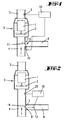
- FIG. 1 Shown and described is first with reference to FIG. 1, an electric motor 1 for a vacuum cleaner, not shown, on which electric motor 1, a driven by this impeller 2 is arranged.
- the blower unit formed thereby is provided with the numeral 3.
- the blower unit 3 is a suction channel 4 and behind the blower unit 3, a suction channel 5 is arranged.
- the temperature in the suction flow direction r behind the electric motor 1, d. H. in the region of the pressure channel 5 by means of a temperature sensor 9, for example.
- a temperature sensor 9 for example.
- the determined temperature value is compared in a control / evaluation unit 10 with a predetermined actual value. If the determined temperature exceeds a predetermined desired value, a signal for opening the secondary air channel is generated.
- the temperature detection can be done by measuring the body temperature or by measuring the Saugstrom Kunststoff temperature in the immediate vicinity of the electric motor 1 or other components to be protected. Further components endangered by high temperatures may be, for example, filters, plastic housing parts or even electronic components.
- the Evaluation electronics in the control / evaluation unit 10 may be constructed discretely or also in the form of a microcontroller, wherein a limit value for generating a control signal for opening the secondary air duct 6 may be fixed or may be present as a variable value.
- the opening 7 of the secondary air channel 6 can basically be arranged arbitrarily on the negative pressure side of the electric motor 1 in the region of the suction channel 4, but preferably an arrangement is selected behind a motor protection filter.
- the opening of the secondary air duct 6 first closing actuator 8 is electrically activated according to the invention, which also spatially remote, formed by actuator 8 and secondary air duct opening 7 valves are controlled.
- the actuator 8 is provided in the form of a bi-metal actuator 11 which is electrically heated when the limit temperature is exceeded until it deforms to release the secondary air duct opening 7 (see dash-dotted representation in Fig. 1). If the temperature drops below the limit value due to the cooling air sucked in via the secondary air duct 6 again, then the heater 12 of the bi-metal actuator 11 is switched off, so that the actuator is returned to close the opening 7.
- FIG. 2 shows a further embodiment in which the present pressure is measured via a pressure sensor 25 in the suction channel 4 and evaluated in a control / evaluation unit 10.
- the actuator 8 is electrically driven to open the secondary air duct 6 from a predetermined limit.
- Shown here is an actuator 8 in the form of a pivotable by means of a servo motor 13 the valve flap 14.
- the temperature in the flow direction r is detected behind it, ie in the pressure channel 5, by means of an electronic temperature sensor 9. Cooling secondary air is supplied when a suitably defined temperature limit is exceeded in that a, the auxiliary air duct opening 7 occlusive actuator 8 is opened under pressure control.
- the switching point of the actuator 8 ie the necessary negative pressure at which an opening occurs., Is set so high that this does not affect regular applications. In general, opening takes place at higher negative pressure values.
- the switching threshold of the actuator 8 is not reached and thus this does not open to allow cooling secondary air to flow.
- the vacuum-controlled actuator is opened against the spring force of a spring 30 acting on the actuator 8 in the closed position, this being due to the fact that the electric motor 1 is controlled via the control / evaluation Unit 10 is spent in a power level at which sufficient negative pressure is generated to exceed the switching threshold of the actuator 8.
Landscapes
- Engineering & Computer Science (AREA)
- Mechanical Engineering (AREA)
- Electric Vacuum Cleaner (AREA)
- Filters For Electric Vacuum Cleaners (AREA)
- Addition Polymer Or Copolymer, Post-Treatments, Or Chemical Modifications (AREA)
- Electric Suction Cleaners (AREA)
Description
- Die Erfindung betrifft zunächst einen Staubsauger mit einem Elektromotor, einem Saugkanal, einem Druckkanal und einem Nebenluftkanal, wobei in Abhängigkeit von der Temperatur in dem Druckkanal eine Öffnung des Nebenluftkanals erfolgt.
- Staubsauger der in Rede stehenden Art sind bekannt. Problematisch erweist sich in bestimmten Fällen die Kühlung des Motors, insbesondere dann, wenn Verstopfungen, bspw. im Bereich des Staubfilters, vorliegen. Eine solche Verstopfung hat zur Folge, dass der Saugluftstrom, der üblicherweise auch die Kühlung des Elektromotors übernimmt, zu gering ist. Bekannte Lösungen weisen eine permanente Nebenluft-Öffnung auf, die so bemessen ist, dass auch bei Verstopfung hinreichend Luft einströmen kann. Weiterhin sind Lösungen bekannt, bei denen unterdruck- oder temperaturgesteuert Ventile geöffnet werden oder die Leistung elektronisch reduziert wird. Prinzipieller Nachteil einer permanenten Öffnung ist es, dass auch bei normalem Betrieb Nebenluft angesaugt wird, so dass der Wirkungsgrad des Gerätes sinkt. Bekannte temperatur- bzw. unterdruckgesteuerte Ventile erweisen sich dahingehend als nachteilig, dass diese Lösungen aufgrund der räumlichen Trennung von Temperaturmessung und Einbauort der Ventile im allgemeinen mechanisch aufwändig sind. Eine elektronische Leistungsreduzierung bis zum Abschalten des Gerätes für zu Irritationen des Benutzers, da dieser nicht erkennt, dass das Herunterregeln bzw. Abschalten zum Schutz des Gerätes gewollt ist und keinesfalls einen Defekt darstellt.
- Aus der US-A-3,936,282 ist ein Staubsauger mit einem Elektromotor, einem Saugkanal, einem Druckkanal und einem Nebenluftkanal bekannt, wobei in Abhängigkeit von der Temperatur in dem Druckkanal eine Öffnung des Nebenluftkanals erfolgt.
- Im Hinblick auf den zuvor beschriebenen Stand der Technik wird eine technische Problematik der Erfindung darin gesehen, einen Staubsauger der in Rede stehenden Art anzugeben, bei welchem ein Schutz vor Überhitzung des Elektromotors mit geringem mechanischem Aufwand realisiert ist.
- Diese Aufgabe ist zunächst und im wesentlichen beim Gegenstand des Anspruches 1 gelöst, wobei darauf abgestellt ist, dass die Aktivierung des Stellorgans zur Öffnung des Nebenluftkanals elektrisch erfolgt. Zum Schutz vor Überhitzung wird Nebenluft zum Kühlen nur dann zugeführt, wenn der Saugstrom im Gerät zu gering wird. Daher wird die Temperatur der zu schützenden Bauteile, insbesondere des Elektromotors, mittels elektronischen Temperatursensoren überwacht. Nur bei Überschreiten eines geeignet definierten Temperatur-Grenzwertes wird Nebenluft zugeführt, vorzugsweise dadurch, dass ein Nebenluft-Ventil des Nebenluftkanals geöffnet wird. So wird bevorzugt erfindungsgemäß die Temperatur mittels eines geeigneten Sensors, z.B. einem NTC oder PTC, im kritischen Bereich überwacht. Bei Überschreiten einer Grenztemperatur wird ein Stellorgan geöffnet. Letzteres verschließt in einer Grundstellung eine saugseitig angebrachte Öffnung des Nebenluftkanals. Der Verschluss erfolgt durch einen Aktuator, welcher im kalten des zu überwachenden Bauteils, bspw. des Elektromotors, die Öffnung des Nebenluftkanals abdeckt. Steigt die Temperatur über den Grenzwert, so wird der Aktuator betätigt, welche Betätigung entgegen dem bekannten Stand der Technik nicht mechanisch über Hebel und Gestänge oder pneumatisch mittels Unterdruckleitungen, sondern elektrisch erfolgt. Zufolge dieser Ausgestaltung werden Temperatur-Informationen des zu überwachenden Bauteils benutzt, um ein räumlich entfernt liegendes Stellorgan zur Öffnung des Nebenluftkanals anzusteuern. Durch die erfindungsgemäße elektrische Aktivierung des Stellorgans ergeben sich kaum Einschränkungen bezüglich des Einbauortes von Temperatursensor und Stellorgan, wobei weiter Grenzwerte exakt eingehalten werden können. Weiter ist von Vorteil, das ein Öffnen des Nebenluftkanals durch die elektrische Aktivierung des Stellorgans ohne Zeitverzögerung erfolgt. Als vorteilhaft erweist sich diesbezüglich weiter, dass ein elektrisch betätigbares Bi-Metall-Stellorgan vorgesehen ist. Dieses oder auch ein Memorymetall wird bei Überschreiten der Grenztemperatur elektrisch beheizt, bis sich dieses verformt und die Luftkanalöffnung freigibt. Sinkt die Temperatur wieder unter den Grenzwert, so wird das Aufheizen des Bi-Metalls beendet, so dass dieses die Öffnung wieder verschließt. Alternativ kann ein elektrisch betätigbares Magnet-Stellorgan vorgesehen sein, welches bei Überschreiten der Grenztemperatur elektrisch angesteuert wird und die Nebenluftkanal-Öffnung freigibt. Des Weiteren kann ein elektrisch betätigbares Piezo-Stellorgan, ein elektro-chemisches Stellorgan oder ein Stellorgan in Form eines Servomotors vorgesehen sein. Durch die erfindungsgemäße elektrische Aktivierung des Stellorgans können auch größere Entfernungen zwischen Stellorgan und Temperatur-Messpunkt in einfachster Weise überbrückt werden, so dass auch andere, durch hohe Temperaturen gefährdete Bauteile, wie bspw. Filter, Kunststoffgehäuseteile oder auch Elektronikbauteile, welche im Luftströmungsweg liegen, geschützt werden. Hierbei kann eine Messung der Körpertemperatur erfolgen. Denkbar ist jedoch auch die Messung der Saugstromluft-Temperatur in unmittelbarer Nähe der zu schützenden Bauteile. Zudem wird vorgeschlagen, eine Auswerte-Elektronik vorzusehen, welche diskret aufgebaut oder auch als Mikrokontroller ausgebildet ist. Diese Auswerte-Elektronik verarbeitet Sensorsignale, welche der Temperatur des zu überwachenden Bauteiles entspricht, auf der Eingangsseite und führt hiernach einen Soll-Ist-Vergleich mit fest eingestellten oder variablen Grenzwerten durch. Bei Überschreiten des Grenzwertes wird ein Schaltsignal für das Stellorgan zur Öffnung des Nebenluftkanals generiert. Das Stellglied bzw. der Nebenluftkanal kann grundsätzlich beliebig auf der Unterdruckseite des Elektromotors vorgesehen sein; bevorzugt jedoch hinter einem Motorschutzfilter.
- Die Erfindung betrifft weiter einen Staubsauger mit einem Elektromotor, einem Saugkanal, einem Druckkanal und einem Nebenluftkanal, wobei in Abhängigkeit vom Druck in dem Saugkanal eine Öffnung des Nebenluftkanals erfolgt. Derartige Staubsauger mit Nebenluftkanal sind hinlänglich bekannt. So offenbart bspw. die US-A 4,124,916 einen solchen Staubsauger. Um einen derartigen Staubsauger in vorteilhafter Weise weiterzubilden, wird vorgeschlagen, dass die Aktivierung des Stellorgans zur Öffnung des Nebenluftkanals elektrisch erfolgt. Eine solche Ausgestaltung erweist sich insbesondere bei Einsatz einer Vorsatzdüse an dem Staubsauger von Vorteil. Hohe Schiebekräfte einer solchen Düse oder anderer Vorsatzgeräte sind gekoppelt an hohe Unterdrücke in den Saugwegen vor der Filterkammer. Übersteigt der Wert für den Unterdruck vor der Filterkammer einen voreingestellten Grenzwert, so wird ein entsprechendes Stellsignal für das Öffnen des Nebenluftkanals generiert, mit der Folge, dass die Schiebekraft sinkt. Ist eine Vorsatzgeräteerkennung vorhanden, so kann dies individuell für jedes Vorsatzgeräte bei unterschiedlichen Grenzwerten erfolgen. Als vorteilhaft erweist sich weiter, dass ein elektrisch betätigbares Bi-Metall-Stellorgan vorgesehen ist, welches bei Überschreiten eines voreingestellten Druck-Grenzwertes elektrisch beheizt wird, bis dieses durch Verformung die Nebenluftkanal-Öffnung freigibt. Alternativ kann auch ein elektrisch betätigbares Magnet-Stellorgan vorgesehen sein. Weiter sind auch elektrisch betätigbare Piezo-Stellorgane, elektro-chemische Stellorgane und Servomotor-Stellorgane einsetzbar.
- Weiter betrifft die Erfindung einen Staubsauger mit einem Elektromotor, einem Saugkanal, einem Druckkanal und einem Nebenluftkanal, wobei in Abhängigkeit von der Temperatur in dem Druckkanal eine Öffnung des Nebenluftkanals erfolgt. Um hier eine Verbesserung hinsichtlich eines Überhitzungsschutzes gefährdeter Bauteile, bspw. des Elektromotors, anzugeben, wird vorgeschlagen, dass die Öffnung des Nebenluftkanals über Unterdruck erfolgt und dass der Elektromotor in Abhängigkeit zur Temperatur im Druckkanal auf eine höhere Drehzahl regelbar ist. Zum Schutz vor Überhitzung wird Nebenluft zum Kühlen nur dann zugeführt, wenn der Saugstrom im Gerät zu gering wird. Daher wird die Temperatur der zu schützenden Bauteile mittels elektronischer Temperatursensoren überwacht. Nur bei Überschreiten eines geeignet definierten Temperatur-Grenzwertes wird Nebenluft zugeführt derart, dass ein Nebenluft-Ventil unterdruckgesteuert geöffnet wird. Der Schaltpunkt des Ventils, d. h. der Unterdruck, bei dem das Ventil öffnet, ist so bemessen, dass hierdurch keine regulären Anwendungen beeinflusst werden. Im allgemeinen öffnet das Ventil bei höheren Unterdruckwerten. Wird der Staubsauger jedoch bei einer niedrigen Leistungseinstellung betrieben, so besteht bei einer starken Verstopfung des Luftströmungsweges, bspw. bei vollständiger Füllung der Filterkammer die Gefahr, dass der Elektromotor des Staubsaugers überhitzt, da in dieser niedrigen Leistungsstufe die Schaltschwelle für das Nebenluftventil nicht erreicht wird und dieses somit nicht öffnet, um kühlende Nebenluft einströmen zu lassen. Erfindungsgemäß werden Schädigungen durch Überhitzung bei niedrigen Leistungsstellungen dadurch vermieden, dass die Temperatur an den gefährdeten Bauteilen, bspw. an dem Elektromotor, durch einen Temperatursensor überwacht wird. Wird ein Temperatur-Grenzwert erreicht, so öffnet das unterdruckgesteuerte Ventil den Nebenluftkanal, und zwar dadurch bedingt, dass der Staubsauger elektronisch in eine Leistungsstufe gebracht wird, bei der hinreichend Unterdruck erzeugt wird, um die Schaltschwelle des Ventils zu überschreiten mit der Folge, dass das Ventil öffnet. Die Aktivierung des Ventils bzw. eines Stellorgans zur Öffnung des Nebenluftkanals kann hierbei elektrisch erfolgen, wobei weiter als Stellorgan ein Bi-Metall- oder ein Magnetaktivator vorgesehen sein kann. Darüber hinaus sind auch Piezo-, elektro-chemische und Servomotor-Stellorgane denkbar. Durch eine erfindungsgemäße Lösung erfolgt ein Sensieren und Überwachen der temperaturgefährdeten Bauteile, z. B. mittels elektrischer Sensoren. Die Temperaturinformationen werden genutzt, um ein räumlich entfernt liegendes Ventil zu öffnen, wobei die Ansteuerung des Ventils nicht mechanisch, sondern über Unterdruck vor dem Motor erfolgt. In einer vorteilhaften Weiterbildung des Erfindungsgegenstandes kann vorgesehen sein, dass der Nebenluftkanal durch eine Klappe verschlossen ist, die bei Überschreiten eines Schwell-Unterdruckes öffnet. Hier kann es sich bspw. um eine in Verschlussrichtung federunterstützte, um eine Achse schwenkbare Verschlusskappe handeln.
- Nachstehend ist die Erfindung anhand der beigefügten Zeichnungen, welche lediglich mehrere Ausführungsbeispiele darstellen, näher erläutert. Es zeigt:
- Fig. 1
- eine schematische Darstellung eines Elektromotors mit einem Saugkanal, einem Druckkanal und einem Nebenluftkanal für einen Staubsauger, eine erste Ausführungsform betreffend;
- Fig. 2
- eine der Fig. 1 entsprechende Darstellung, jedoch eine zweite Ausführungsform betreffend;
- Fig. 3
- eine weitere, der Fig.1 entsprechende Darstellung, eine dritte Ausführungsform betreffend;
- Fig. 4
- in einer vierten Ausführungsform, den Erfindungsgegenstand in einer Darstellung gemäß Fig. 1 zeigend.
- Dargestellt und beschrieben ist zunächst mit Bezug zu Fig. 1 ein Elektromotor 1 für einen nicht näher dargestellten Staubsauger, an welchem Elektromotor 1 ein durch diesen angetriebenes Gebläserad 2 angeordnet ist. Die hierdurch gebildete Gebläseeinheit ist mit der Ziffer 3 versehen.
- In Saugrichtung r ist der Gebläseeinheit 3 ein Saugkanal 4 und hinter der Gebläseeinheit 3 ein Saugkanal 5 angeordnet.
- In den Saugkanal 4, d. h. in Saugrichtung r vor der Gebläseeinheit 3 mündet ein Nebenluftkanal 6, dessen saugkanalseitige Öffnung mittels eines Stellorgans 8 in einer Grundstellung gemäß Fig.1 verschlossen ist.
- Der Saugluftstrom übernimmt zugleich die Kühlung des Elektromotors 1. Störungen, wie bspw. Verstopfungen, können jedoch zu einer derartigen Reduzierung des Saugluftstromes führen, dass eine ausreichende Kühlung des Elektromotors 1 nicht mehr gegeben ist. Um hier den Elektromotor vor Schäden durch Überhitzung zu schützen, wird die Temperatur in Saugstromrichtung r hinter dem Elektromotor 1, d. h. im Bereich des Druckkanals 5 mittels eines Temperatursensors 9, bspw. in Form eines NTC, erfasst. Der ermittelte Temperaturwert wird in einer Steuer-/Auswert-Einheit 10 mit einem vorgegebenen Ist-Wert verglichen. Übersteigt die ermittelte Temperatur einen vorgegebenen Soll-Wert, so wird ein Signal zum Öffnen des Nebenluftkanals generiert.
- Die Temperaturerfassung kann mittels Messung der Körpertemperatur oder auch durch Messung der Saugstromluft-Temperatur in unmittelbarer Nähe des Elektromotors 1 bzw. auch anderer zu schützender Bauteile erfolgen. Weitere durch hohe Temperaturen gefährdete Bauteile können bspw. Filter, Kunststoffgehäuseteile oder auch Elektronikbauteile sein. Die Auswerteelektronik in der Steuer-/Auswerteeinheit 10 kann diskret aufgebaut oder auch in Form eines Mikrokontrollers ausgebildet sein, wobei ein Grenzwert zur Generierung eines Steuersignals zum Öffnen des Nebenluftkanals 6 fest voreingestellt sein oder auch als variabler Wert vorliegen kann.
- Die Öffnung 7 des Nebenluftkanals 6 kann grundsätzlich beliebig auf der Unterdruckseite des Elektromotors 1 im Bereich des Saugkanals 4 angeordnet sein, wobei jedoch bevorzugt eine Anordnung hinter einem Motorschutzfilter gewählt wird.
- Das die Öffnung des Nebenluftkanals 6 zunächst verschließende Stellorgan 8 wird erfindungsgemäß elektrisch aktiviert, womit auch räumlich entfernt liegende, durch Stellorgan 8 und Nebenluftkanal-Öffnung 7 gebildete Ventile ansteuerbar sind.
- In dem dargestellten Ausführungsbeispiel ist das Stellorgan 8 in Form eines Bi-Metall-Stellorgans 11 vorgesehen, welches bei Überschreiten der Grenztemperatur elektrisch beheizt wird, bis es sich zur Freigabe der Nebenluftkanal-Öffnung 7 verformt (siehe strichpunktierte Darstellung in Fig. 1). Sinkt die Temperatur aufgrund der über den Nebenluftkanal 6 angesaugten Kühlluft wieder unter den Grenzwert, so wird die Heizung 12 des Bi-Metall-Stellorgans 11 ausgeschaltet, so dass eine Rückstellung des Stellorgans unter Verschließen der Öffnung 7 erfolgt.
- Alternativ zu dem dargestellten Stellorgan 8 ist es auch denkbar, ein Magnet-Stellorgan vorzusehen, welches bei Überschreiten der Grenztemperatur elektrisch angesteuert wird und die Nebenluftkanal-Öffnung 7 freigibt. Darüber hinaus sind auch Piezo-Elemente oder elektro-chemische Aktuatoren als Stellorgane denkbar.
- In Fig. 2 ist eine weitere Ausführungsform dargestellt, bei welcher über einen Drucksensor 25 im Saugkanal 4 der vorliegende Druck gemessen und in einer Steuer-/Auswerteeinheit 10 ausgewertet wird. Über letztere wird ab einem vorbestimmten Grenzwert das Stellorgan 8 elektrisch zum Öffnen des Nebenluftkanals 6 angesteuert. Dargestellt ist hier ein Stellorgan 8 in Form einer mittels eines Servo-Motors 13 schwenkbeweglichen Ventilklappe 14. Denkbar sind hier jedoch auch Lösungen des Stellorgans 8 gemäß dem ersten Ausführungsbeispiel, d. h. in Form eines Bi-Metal-Stellorgans 11, eines Magnet-Stellorgans oder eines Stellorgans in Form eines Piezo-Elementes oder eines elektro-chemischen Aktuators.
- In der Ausführungsform gemäß Fig. 3 wird zum Schutz vor einer Überhitzung des Elektromotors 1 die Temperatur in Strömungsrichtung r hinter demselben, d. h. im Druckkanal 5, erfasst, dies mittels eines elektronischen Temperatursensors 9. Bei Überschreiten eines geeignet definierten Temperatur-Grenzwertes wird kühlende Nebenluft zugeführt, indem ein, die Nebenluftkanal-Öffnung 7 verschließendes Stellorgan 8 unterdruckgesteuert geöffnet wird. Der Schaltpunkt des Stellorgans 8, d. h. der nötige Unterdruck, bei welchem eine Öffnung erfolgt., ist so hoch angelegt, dass hierdurch keine regulären Anwendungen beeinflusst werden. Im allgemeinen erfolgt ein Öffnen bei höheren Unterdruckwerten. Wird der Staubsauger jedoch bei einer niedrigen Leistungsstellung betrieben, so besteht bei einer Verstopfung die Gefahr, dass der Elektromotor überhitzt, da in dieser niedrigen Leistungsstufe die Schaltschwelle des Stellorgans 8 nicht erreicht wird und dieses somit nicht öffnet, um kühlende Nebenluft einströmen zu lassen.
- Um eine Schädigung zu vermeiden, muss Nebenluft zugeführt werden. Wird in einer kleinen Leistungsstufe des Elektromotors der Temperatur-Grenzwert erreicht, so wird das unterdruckgesteuerte Stellorgan entgegen der Federkraft einer das Stellorgan 8 in die Schließstellung beaufschlagenden Feder 30 geöffnet, dies dadurch bedingt, dass der Elektromotor 1 mittels Ansteuerung über die Steuer-/Auswert-Einheit 10 in eine Leistungsstufe verbracht wird, bei welcher hinreichend Unterdruck erzeugt wird, um die Schaltschwelle des Stellorgans 8 zu überschreiten.
Claims (14)
- Staubsauger mit einem Elektromotor (1), einem Saugkanal (4), einem Druckkanal (5) und einem Nebenluftkanal (6), wobei in Abhängigkeit von der Temperatur in dem Druckkanal (5) eine Öffnung des Nebenluftkanals (6) erfolgt, dadurch gekennzeichnet, dass die Aktivierung eines Stellorgans (8) zur Öffnung des Nebenluftkanals (6) elektrisch erfolgt.
- Staubsauger nach Anspruch 1, dadurch gekennzeichnet, dass ein elektrisch betätigbares Bi-Metall-Stellorgan (11) vorgesehen ist.
- Staubsauger nach Anspruch 1, dadurch gekennzeichnet, dass ein elektrisch betätigbares Magnet-Stellorgan vorgesehen ist.
- Staubsauger nach Anspruch 1, dadurch gekennzeichnet, dass ein elektrisch betätigbares Piezo-Stellorgan vorgesehen ist.
- Staubsauger nach Anspruch 1, dadurch gekennzeichnet, dass ein elektrisch betätigbares elektro-chemisches Stellorganvorgesehen ist.
- Staubsauger nach Anspruch 1, dadurch gekennzeichnet, dass ein elektrisch betätigbares Servomotor-Stellorgan (13) vorgesehen ist.
- Staubsauger mit einem Elektromotor (1), einem Saugkanal (4), einem Druckkanal (5) und einem Nebenluftkanal (6), wobei in Abhängigkeit vom Druck in dem Saugkanal(4) eine Öffnung des Nebenluftkanals (6) erfolgt, dadurch gekennzeichnet, dass die Aktivierung eines Stellorgans (8) zur Öffnung des Nebenluftkanals (6) elektrisch erfolgt.
- Staubsauger nach Anspruch 7, dadurch gekennzeichnet, dass ein elektrisch betätigbares Bi-Metall-Stellorgan (11) vorgesehen ist.
- Staubsauger nach Anspruch 7, dadurch gekennzeichnet, dass ein elektrisch betätigbares Magnet-Stellorgan vorgesehen ist.
- Staubsauger nach Anspruch 7, dadurch gekennzeichnet, dass ein elektrisch betätigbares Piezo-Stellorgan vorgesehen ist.
- Staubsauger nach Anspruch 7, dadurch gekennzeichnet, dass ein elektrisch betätigbares elektro-chemisches Stellorgan vorgesehen ist.
- Staubsauger nach Anspruch 7, dadurch gekennzeichnet, dass ein elektrisch betätigbares Servomotor-Stellorgan vorgesehen ist.
- Staubsauger mit einem Elektromotor (1), einem Saugkanal (4), einem Druckkanal (5) und einem Nebenluftkanal (6), wobei in Abhängigkeit von der Temperatur in dem Druckkanal (5) eine Öffnung des Nebenluftkanals (6) über Unterdruck erfolgt und dass der Elektromotor (1) in Abhängigkeit zur Temperatur im Druckkanal (5) auf eine höhere Drehzahl regelbar ist.
- Staubsauger nach Anspruch 13, dadurch gekennzeichnet, dass der Nebenluftkanal (6) durch eine Klappe (14) verschlossen ist, die bei Überschreiten eines Schwell-Unterdruckes öffnet.
Priority Applications (1)
| Application Number | Priority Date | Filing Date | Title |
|---|---|---|---|
| EP06118794A EP1731074B1 (de) | 2000-07-21 | 2001-07-05 | Staubsauger |
Applications Claiming Priority (5)
| Application Number | Priority Date | Filing Date | Title |
|---|---|---|---|
| DE10035482 | 2000-07-21 | ||
| DE10035482 | 2000-07-21 | ||
| DE10129596A DE10129596A1 (de) | 2000-07-21 | 2001-06-20 | Staubsauger |
| DE10129596 | 2001-06-20 | ||
| PCT/EP2001/007701 WO2002007579A1 (de) | 2000-07-21 | 2001-07-05 | Staubsauger |
Related Child Applications (1)
| Application Number | Title | Priority Date | Filing Date |
|---|---|---|---|
| EP06118794A Division EP1731074B1 (de) | 2000-07-21 | 2001-07-05 | Staubsauger |
Publications (2)
| Publication Number | Publication Date |
|---|---|
| EP1301114A1 EP1301114A1 (de) | 2003-04-16 |
| EP1301114B1 true EP1301114B1 (de) | 2006-11-15 |
Family
ID=26006467
Family Applications (1)
| Application Number | Title | Priority Date | Filing Date |
|---|---|---|---|
| EP01951652A Expired - Lifetime EP1301114B1 (de) | 2000-07-21 | 2001-07-05 | Staubsauger |
Country Status (5)
| Country | Link |
|---|---|
| EP (1) | EP1301114B1 (de) |
| AT (1) | ATE345081T1 (de) |
| DE (1) | DE50111459D1 (de) |
| ES (1) | ES2271046T3 (de) |
| WO (1) | WO2002007579A1 (de) |
Cited By (1)
| Publication number | Priority date | Publication date | Assignee | Title |
|---|---|---|---|---|
| US20200054181A1 (en) * | 2015-01-28 | 2020-02-20 | Techtronic Industries Co. Ltd. | Above floor air bleed |
Families Citing this family (1)
| Publication number | Priority date | Publication date | Assignee | Title |
|---|---|---|---|---|
| CN119255739A (zh) * | 2022-05-24 | 2025-01-03 | 新埃莫斯欧洲有限责任公司 | 具有优化推力的清洁头 |
Family Cites Families (10)
| Publication number | Priority date | Publication date | Assignee | Title |
|---|---|---|---|---|
| NL274310A (de) * | 1961-02-04 | |||
| DE2246961A1 (de) * | 1972-09-25 | 1974-04-04 | Siemens Elektrogeraete Gmbh | Anzeigevorrichtung fuer den fuellgrad eines staubsaugerfilters |
| SE381982B (sv) * | 1974-03-01 | 1976-01-12 | Electrolux Ab | Anordning vid dammsugare innefattande en av ett temperaturkensligt organ paverkbar ventil |
| US4124916A (en) * | 1977-08-04 | 1978-11-14 | The Singer Company | Vacuum cleaner condition indicator and safety device |
| DE2819193A1 (de) * | 1978-05-02 | 1979-11-08 | Siemens Ag | Staubsauger mit einer drehzahlregeleinrichtung fuer das geblaeseaggregat |
| DE2911255C2 (de) * | 1979-03-22 | 1986-09-25 | Licentia Patent-Verwaltungs-Gmbh, 6000 Frankfurt | Staubsauger |
| DE2917142A1 (de) * | 1979-04-27 | 1980-11-06 | Mauz & Pfeiffer Progress | Staubsauger fuer haushalt, gewerbe o.dgl. |
| JP3146881B2 (ja) * | 1994-10-07 | 2001-03-19 | 松下電器産業株式会社 | 電気掃除機の制御装置 |
| GB2315231A (en) * | 1996-07-15 | 1998-01-28 | Notetry Ltd | Apparatus for Separating Particles |
| JPH11318772A (ja) * | 1998-05-21 | 1999-11-24 | Matsushita Electric Ind Co Ltd | 電気掃除機 |
-
2001
- 2001-07-05 WO PCT/EP2001/007701 patent/WO2002007579A1/de not_active Ceased
- 2001-07-05 DE DE50111459T patent/DE50111459D1/de not_active Expired - Lifetime
- 2001-07-05 AT AT01951652T patent/ATE345081T1/de active
- 2001-07-05 EP EP01951652A patent/EP1301114B1/de not_active Expired - Lifetime
- 2001-07-05 ES ES01951652T patent/ES2271046T3/es not_active Expired - Lifetime
Cited By (1)
| Publication number | Priority date | Publication date | Assignee | Title |
|---|---|---|---|---|
| US20200054181A1 (en) * | 2015-01-28 | 2020-02-20 | Techtronic Industries Co. Ltd. | Above floor air bleed |
Also Published As
| Publication number | Publication date |
|---|---|
| ES2271046T3 (es) | 2007-04-16 |
| DE50111459D1 (de) | 2006-12-28 |
| EP1301114A1 (de) | 2003-04-16 |
| WO2002007579A1 (de) | 2002-01-31 |
| ATE345081T1 (de) | 2006-12-15 |
Similar Documents
| Publication | Publication Date | Title |
|---|---|---|
| EP1758007B1 (de) | Fluidbetätigter Stellungsregler | |
| EP0128365B1 (de) | Vorichtung zum Kühlen eines Verbrennungsmotors | |
| DE102010054979B4 (de) | Ventilanordnung und Verfahren zum Betätigen eines Ventils | |
| DE102011008305B4 (de) | Vorrichtung zur Betätigung eines Stellventils | |
| EP1731074A2 (de) | Staubsauger | |
| DE202017007441U1 (de) | Staubsauger | |
| DE102009004570B4 (de) | Verfahren und elektronische Einrichtung zum Finden des Öffnungspunktes bei einem geregelten elektro-pneumatischen Ventil eines pneumatischen Stellantriebs | |
| CH664808A5 (de) | Regelventil fuer heizkoerper. | |
| EP2657584B1 (de) | Ventil mit einer vorrichtung zur überwachung von dessen funktionalität | |
| EP0589153B1 (de) | Vorrichtung zur Regelung der Temperatur der Ansaugluft von Brennkraftmaschinen | |
| US20200132208A1 (en) | Variable flow controlled diaphragm valve based on shape memory alloy | |
| WO2002007579A1 (de) | Staubsauger | |
| DE20313289U1 (de) | Trockenlaufschutz | |
| DE2833833A1 (de) | Vorrichtung zur regelung der temperatur der ansaugluft von brennkraftmaschinen | |
| EP0544985B1 (de) | Temperaturregeleinrichtung für das Kühlmittel von Brennkraftmaschinen | |
| DE102016206709A1 (de) | Versorgungseinrichtung, Versorgungssystem und Verfahren zur individuellen Versorgung eines Druckluftverbrauchers | |
| DE102014104959A1 (de) | System und Verfahren zum Steuern eines Aktors aus aktiven Materialien | |
| DE202008014236U1 (de) | Einrichtung zur Kühlung eines zu Mess- oder Überwachungszwecken vorgsehenen Sensors | |
| DE102011078388A1 (de) | Nebenluftventil und Staubsauger | |
| DE2732916A1 (de) | Temperaturabhaengiger elektronischer regelschalter | |
| EP0984257A1 (de) | Selbsttätig abgleichbare Einrichtung zur Messung einer Druckdifferenz | |
| DE2846444C2 (de) | Regelungsvorrichtung, insbesondere für Fahrzeuge, für eine Heizungs- oder Klimaanlage | |
| DE102014004509B4 (de) | Regelvorrichtung | |
| DE102006049651B4 (de) | Positionsgeber und Anordnung mit pneumatischem Antrieb | |
| DE1498185A1 (de) | Elektropneumatischer Wandler fuer Regelgeraete |
Legal Events
| Date | Code | Title | Description |
|---|---|---|---|
| PUAI | Public reference made under article 153(3) epc to a published international application that has entered the european phase |
Free format text: ORIGINAL CODE: 0009012 |
|
| AK | Designated contracting states |
Designated state(s): AT BE CH CY DE DK ES FI FR GB GR IE IT LI LU MC NL PT SE TR |
|
| AX | Request for extension of the european patent |
Extension state: LT LV RO SI |
|
| 17P | Request for examination filed |
Effective date: 20030116 |
|
| RIN1 | Information on inventor provided before grant (corrected) |
Inventor name: SCHEUREN, BERNHARD Inventor name: FIESELER, MARTIN Inventor name: HOFFMANN, THOMAS |
|
| GRAP | Despatch of communication of intention to grant a patent |
Free format text: ORIGINAL CODE: EPIDOSNIGR1 |
|
| GRAS | Grant fee paid |
Free format text: ORIGINAL CODE: EPIDOSNIGR3 |
|
| GRAA | (expected) grant |
Free format text: ORIGINAL CODE: 0009210 |
|
| AK | Designated contracting states |
Kind code of ref document: B1 Designated state(s): AT BE CH CY DE DK ES FI FR GB GR IE IT LI LU MC NL PT SE TR |
|
| PG25 | Lapsed in a contracting state [announced via postgrant information from national office to epo] |
Ref country code: FI Free format text: LAPSE BECAUSE OF FAILURE TO SUBMIT A TRANSLATION OF THE DESCRIPTION OR TO PAY THE FEE WITHIN THE PRESCRIBED TIME-LIMIT Effective date: 20061115 Ref country code: IE Free format text: LAPSE BECAUSE OF FAILURE TO SUBMIT A TRANSLATION OF THE DESCRIPTION OR TO PAY THE FEE WITHIN THE PRESCRIBED TIME-LIMIT Effective date: 20061115 |
|
| REG | Reference to a national code |
Ref country code: GB Ref legal event code: FG4D Free format text: NOT ENGLISH |
|
| GBT | Gb: translation of ep patent filed (gb section 77(6)(a)/1977) |
Effective date: 20061115 |
|
| REG | Reference to a national code |
Ref country code: CH Ref legal event code: EP |
|
| REF | Corresponds to: |
Ref document number: 50111459 Country of ref document: DE Date of ref document: 20061228 Kind code of ref document: P |
|
| REG | Reference to a national code |
Ref country code: IE Ref legal event code: FG4D Free format text: LANGUAGE OF EP DOCUMENT: GERMAN |
|
| PG25 | Lapsed in a contracting state [announced via postgrant information from national office to epo] |
Ref country code: DK Free format text: LAPSE BECAUSE OF FAILURE TO SUBMIT A TRANSLATION OF THE DESCRIPTION OR TO PAY THE FEE WITHIN THE PRESCRIBED TIME-LIMIT Effective date: 20070215 |
|
| REG | Reference to a national code |
Ref country code: SE Ref legal event code: TRGR |
|
| PG25 | Lapsed in a contracting state [announced via postgrant information from national office to epo] |
Ref country code: PT Free format text: LAPSE BECAUSE OF FAILURE TO SUBMIT A TRANSLATION OF THE DESCRIPTION OR TO PAY THE FEE WITHIN THE PRESCRIBED TIME-LIMIT Effective date: 20070416 |
|
| REG | Reference to a national code |
Ref country code: ES Ref legal event code: FG2A Ref document number: 2271046 Country of ref document: ES Kind code of ref document: T3 |
|
| ET | Fr: translation filed | ||
| REG | Reference to a national code |
Ref country code: IE Ref legal event code: FD4D |
|
| PLBE | No opposition filed within time limit |
Free format text: ORIGINAL CODE: 0009261 |
|
| STAA | Information on the status of an ep patent application or granted ep patent |
Free format text: STATUS: NO OPPOSITION FILED WITHIN TIME LIMIT |
|
| 26N | No opposition filed |
Effective date: 20070817 |
|
| PGFP | Annual fee paid to national office [announced via postgrant information from national office to epo] |
Ref country code: TR Payment date: 20070605 Year of fee payment: 7 |
|
| PGFP | Annual fee paid to national office [announced via postgrant information from national office to epo] |
Ref country code: GB Payment date: 20070705 Year of fee payment: 7 |
|
| BERE | Be: lapsed |
Owner name: VORWERK & CO. INTERHOLDING G.M.B.H. Effective date: 20070731 |
|
| PGFP | Annual fee paid to national office [announced via postgrant information from national office to epo] |
Ref country code: NL Payment date: 20070704 Year of fee payment: 7 Ref country code: SE Payment date: 20070706 Year of fee payment: 7 |
|
| REG | Reference to a national code |
Ref country code: CH Ref legal event code: PL |
|
| PG25 | Lapsed in a contracting state [announced via postgrant information from national office to epo] |
Ref country code: LI Free format text: LAPSE BECAUSE OF NON-PAYMENT OF DUE FEES Effective date: 20070731 Ref country code: CH Free format text: LAPSE BECAUSE OF NON-PAYMENT OF DUE FEES Effective date: 20070731 Ref country code: MC Free format text: LAPSE BECAUSE OF NON-PAYMENT OF DUE FEES Effective date: 20070731 Ref country code: GR Free format text: LAPSE BECAUSE OF FAILURE TO SUBMIT A TRANSLATION OF THE DESCRIPTION OR TO PAY THE FEE WITHIN THE PRESCRIBED TIME-LIMIT Effective date: 20070216 |
|
| PG25 | Lapsed in a contracting state [announced via postgrant information from national office to epo] |
Ref country code: BE Free format text: LAPSE BECAUSE OF NON-PAYMENT OF DUE FEES Effective date: 20070731 |
|
| EUG | Se: european patent has lapsed | ||
| GBPC | Gb: european patent ceased through non-payment of renewal fee |
Effective date: 20080705 |
|
| NLV4 | Nl: lapsed or anulled due to non-payment of the annual fee |
Effective date: 20090201 |
|
| PG25 | Lapsed in a contracting state [announced via postgrant information from national office to epo] |
Ref country code: NL Free format text: LAPSE BECAUSE OF NON-PAYMENT OF DUE FEES Effective date: 20090201 |
|
| PG25 | Lapsed in a contracting state [announced via postgrant information from national office to epo] |
Ref country code: GB Free format text: LAPSE BECAUSE OF NON-PAYMENT OF DUE FEES Effective date: 20080705 |
|
| PG25 | Lapsed in a contracting state [announced via postgrant information from national office to epo] |
Ref country code: LU Free format text: LAPSE BECAUSE OF NON-PAYMENT OF DUE FEES Effective date: 20070705 Ref country code: CY Free format text: LAPSE BECAUSE OF FAILURE TO SUBMIT A TRANSLATION OF THE DESCRIPTION OR TO PAY THE FEE WITHIN THE PRESCRIBED TIME-LIMIT Effective date: 20061115 |
|
| PG25 | Lapsed in a contracting state [announced via postgrant information from national office to epo] |
Ref country code: SE Free format text: LAPSE BECAUSE OF NON-PAYMENT OF DUE FEES Effective date: 20080706 |
|
| PG25 | Lapsed in a contracting state [announced via postgrant information from national office to epo] |
Ref country code: TR Free format text: LAPSE BECAUSE OF NON-PAYMENT OF DUE FEES Effective date: 20100927 |
|
| PG25 | Lapsed in a contracting state [announced via postgrant information from national office to epo] |
Ref country code: TR Free format text: LAPSE BECAUSE OF NON-PAYMENT OF DUE FEES Effective date: 20080705 |
|
| REG | Reference to a national code |
Ref country code: FR Ref legal event code: PLFP Year of fee payment: 16 |
|
| REG | Reference to a national code |
Ref country code: FR Ref legal event code: PLFP Year of fee payment: 17 |
|
| REG | Reference to a national code |
Ref country code: FR Ref legal event code: PLFP Year of fee payment: 18 |
|
| PGFP | Annual fee paid to national office [announced via postgrant information from national office to epo] |
Ref country code: FR Payment date: 20200727 Year of fee payment: 20 Ref country code: DE Payment date: 20200723 Year of fee payment: 20 Ref country code: ES Payment date: 20200818 Year of fee payment: 20 |
|
| PGFP | Annual fee paid to national office [announced via postgrant information from national office to epo] |
Ref country code: IT Payment date: 20200731 Year of fee payment: 20 Ref country code: AT Payment date: 20200720 Year of fee payment: 20 |
|
| REG | Reference to a national code |
Ref country code: DE Ref legal event code: R071 Ref document number: 50111459 Country of ref document: DE |
|
| REG | Reference to a national code |
Ref country code: AT Ref legal event code: MK07 Ref document number: 345081 Country of ref document: AT Kind code of ref document: T Effective date: 20210705 |
|
| REG | Reference to a national code |
Ref country code: ES Ref legal event code: FD2A Effective date: 20211013 |
|
| PG25 | Lapsed in a contracting state [announced via postgrant information from national office to epo] |
Ref country code: ES Free format text: LAPSE BECAUSE OF EXPIRATION OF PROTECTION Effective date: 20210706 |