EP1300859A2 - Switch operating mechanism - Google Patents
Switch operating mechanism Download PDFInfo
- Publication number
- EP1300859A2 EP1300859A2 EP02022122A EP02022122A EP1300859A2 EP 1300859 A2 EP1300859 A2 EP 1300859A2 EP 02022122 A EP02022122 A EP 02022122A EP 02022122 A EP02022122 A EP 02022122A EP 1300859 A2 EP1300859 A2 EP 1300859A2
- Authority
- EP
- European Patent Office
- Prior art keywords
- switch
- pusher
- pressing arm
- operating knob
- circuit board
- Prior art date
- Legal status (The legal status is an assumption and is not a legal conclusion. Google has not performed a legal analysis and makes no representation as to the accuracy of the status listed.)
- Granted
Links
Images


Classifications
-
- H—ELECTRICITY
- H01—ELECTRIC ELEMENTS
- H01H—ELECTRIC SWITCHES; RELAYS; SELECTORS; EMERGENCY PROTECTIVE DEVICES
- H01H21/00—Switches operated by an operating part in the form of a pivotable member acted upon directly by a solid body, e.g. by a hand
- H01H21/02—Details
- H01H21/18—Movable parts; Contacts mounted thereon
- H01H21/22—Operating parts, e.g. handle
- H01H21/24—Operating parts, e.g. handle biased to return to normal position upon removal of operating force
-
- H—ELECTRICITY
- H01—ELECTRIC ELEMENTS
- H01H—ELECTRIC SWITCHES; RELAYS; SELECTORS; EMERGENCY PROTECTIVE DEVICES
- H01H19/00—Switches operated by an operating part which is rotatable about a longitudinal axis thereof and which is acted upon directly by a solid body external to the switch, e.g. by a hand
- H01H19/54—Switches operated by an operating part which is rotatable about a longitudinal axis thereof and which is acted upon directly by a solid body external to the switch, e.g. by a hand the operating part having at least five or an unspecified number of operative positions
- H01H19/60—Angularly-movable actuating part carrying no contacts
- H01H19/635—Contacts actuated by rectilinearly-movable member linked to operating part, e.g. by pin and slot
-
- H—ELECTRICITY
- H01—ELECTRIC ELEMENTS
- H01H—ELECTRIC SWITCHES; RELAYS; SELECTORS; EMERGENCY PROTECTIVE DEVICES
- H01H2221/00—Actuators
- H01H2221/008—Actuators other then push button
- H01H2221/016—Lever; Rocker
-
- Y—GENERAL TAGGING OF NEW TECHNOLOGICAL DEVELOPMENTS; GENERAL TAGGING OF CROSS-SECTIONAL TECHNOLOGIES SPANNING OVER SEVERAL SECTIONS OF THE IPC; TECHNICAL SUBJECTS COVERED BY FORMER USPC CROSS-REFERENCE ART COLLECTIONS [XRACs] AND DIGESTS
- Y10—TECHNICAL SUBJECTS COVERED BY FORMER USPC
- Y10T—TECHNICAL SUBJECTS COVERED BY FORMER US CLASSIFICATION
- Y10T74/00—Machine element or mechanism
- Y10T74/20—Control lever and linkage systems
- Y10T74/20012—Multiple controlled elements
- Y10T74/20018—Transmission control
- Y10T74/2003—Electrical actuator
-
- Y—GENERAL TAGGING OF NEW TECHNOLOGICAL DEVELOPMENTS; GENERAL TAGGING OF CROSS-SECTIONAL TECHNOLOGIES SPANNING OVER SEVERAL SECTIONS OF THE IPC; TECHNICAL SUBJECTS COVERED BY FORMER USPC CROSS-REFERENCE ART COLLECTIONS [XRACs] AND DIGESTS
- Y10—TECHNICAL SUBJECTS COVERED BY FORMER USPC
- Y10T—TECHNICAL SUBJECTS COVERED BY FORMER US CLASSIFICATION
- Y10T74/00—Machine element or mechanism
- Y10T74/20—Control lever and linkage systems
- Y10T74/20012—Multiple controlled elements
- Y10T74/20018—Transmission control
- Y10T74/2014—Manually operated selector [e.g., remotely controlled device, lever, push button, rotary dial, etc.]
-
- Y—GENERAL TAGGING OF NEW TECHNOLOGICAL DEVELOPMENTS; GENERAL TAGGING OF CROSS-SECTIONAL TECHNOLOGIES SPANNING OVER SEVERAL SECTIONS OF THE IPC; TECHNICAL SUBJECTS COVERED BY FORMER USPC CROSS-REFERENCE ART COLLECTIONS [XRACs] AND DIGESTS
- Y10—TECHNICAL SUBJECTS COVERED BY FORMER USPC
- Y10T—TECHNICAL SUBJECTS COVERED BY FORMER US CLASSIFICATION
- Y10T74/00—Machine element or mechanism
- Y10T74/20—Control lever and linkage systems
- Y10T74/20576—Elements
- Y10T74/20732—Handles
- Y10T74/20834—Hand wheels
Definitions
- the present invention relates to a switch operating mechanism in which an operator turns a switch on and/or off by pressing the switch provided at a circuit board.
- Some automobile steering wheels are equipped with, for example, a switch for shifting gears.
- a switch for shifting gears there is a type which is arranged to activate the switch by moving the operating knob upward so that the switch can be operated while an operator is holding the steering wheel.
- a switch operating mechanism 50 of this type includes a circuit board 12 with a switch 14 (a contact member held by rubber) and an operating knob 54 that is supported by a spindle 52 so as to rotate about the spindle 52, which is provided at a lower position than the switch 14 as schematically illustrated in Fig. 4B.
- the operating knob 54 rotates about the spindle 52, and a front end 54A of the operating knob 54 presses a pusher 56 downward, thereby turning the switch 14 on and/or off (i.e., a hinge-type operating knob).
- the conventional switch operating mechanism 50 has some drawbacks.
- the operating knob 54 is cranked to operate the switch 14. Further, since the switch operating mechanism 50 is supported by a spindle provided at a lower position than the switch 14, the front end 54A of the operating knob 54 (the portion of the operating knob that presses the pusher 56) moves along an arcuate path around the spindle 52. Components of the pressing force act not only in an axial direction of the pusher 56 but also in a direction perpendicular thereto, and the relationship between a force F pressing the switch 14 and an operation stroke S deteriorates. As a result, operational feeling of the operating knob 54 is impaired. Moreover, there is a demand for using the space above the circuit board 12 effectively. However, a guide mechanism for guiding the pusher 56 occupies the space above the circuit board 12, making it impossible to use the space for other purposes in other ways.
- an object of the present invention is to provide a switch operating mechanism, which has an operating knob that gives the operator an improved operational feeling and, at the same time, meets the demand for effective use of the space above the circuit board.
- a first aspect of the present invention is a switch operating mechanism for turning a switch on and/or off by pressing the switch, which is provided at a circuit board, the mechanism comprising: an operating knob, which has a front end and a back end and is rotatably supported by a spindle that is provided at a lower position than the switch; and a pusher having a base, a first pressing arm, and a second pressing arm, the first pressing arm and the second pressing arm extending parallel to each other from both ends of the base in a direction perpendicular to an axial direction of the base such that the pusher has a substantial U-shape when seen in side view, wherein the switch of the circuit board is disposed between the first and the second pressing arms of the pusher, the first pressing arm being positioned directly above the switch and able to press the same; the operating knob is disposed such that the front end thereof is disposed between the circuit board and the second pressing arm so that the front end is able to press the second pressing arm; and when the back end of the operating knob is
- the switch operating mechanism of the first aspect of the present invention when the operator moves the operating knob upward, the operating knob rotates and the front end thereof moves the second pressing arm of the pusher downward.
- the pusher moves linearly along the direction perpendicular to the plane of the circuit board, and the first pressing arm of the pusher presses the switch to turn the switch on and/or off.
- the operating knob is supported by the spindle, which is disposed at a lower position than the switch, and the pusher is formed in a substantial U-shape when seen in side view. Accordingly, even if the front end of the operating knob (the portion of the operating knob that presses the second pressing arm of the pusher) moves along an arcuate path around the spindle, the linear movement of the pusher presses and activates the switch. Thus, operational feeling of the operating knob, i.e., a relationship between a force pressing the switch and an operation stroke can be much closer to an ideal relationship. Further, in the switch operating mechanism, the switch of the circuit board is disposed between the first and the second pressing arms of the pusher.
- a guide mechanism for guiding the pusher may be provided along the base of the pusher (at the base side of the pusher). In other words, it is not necessary to provide the guide mechanism above the circuit board, whereby the space above the circuit board can be used effectively.
- a second aspect of the present invention is a switch operating mechanism provided in a vehicle, for turning a switch on and/or off by pressing the switch provided at a circuit board, the mechanism comprising: an operating knob, which has a front end and a back end and is rotatably supported by a spindle that is provided at a lower position than the switch; and a pusher having a base, a first pressing arm, and a second pressing arm, the first pressing arm and the second pressing arm extending parallel to each other from both ends of the base in a direction perpendicular to an axial direction of the base such that the pusher has a substantial U-shape when seen in side view, wherein the switch of the circuit board is disposed between the first and the second pressing arms of the pusher, the first pressing arm being positioned directly above the switch and able to press the same; the operating knob is disposed such that the front end thereof is disposed between the circuit board and the second pressing arm so that the front end is able to press the second pressing arm; and when the back end of the
- a third aspect of the present invention is a method of manufacturing a switch operating mechanism for turning a switch on and/or off by pressing the switch, the method comprising the steps of: a. manufacturing a operating knob having a front end and a back end; b. manufacturing a pusher having a base, a first pressing arm, and a second pressing arm, the first pressing arm and the second pressing arm extending parallel to each other from both ends of the base in a direction perpendicular to an axial direction of the base such that the pusher has a substantial U-shape when seen in side view; c. mounting the operating knob to a spindle provided at a lower position than the switch so as to rotate about the spindle; and d. disposing the switch and the front end of the operating knob between the first pressing arm and the second pressing arm.
- a switch operating mechanism 10 relating to an embodiment of the present invention is provided at, for example, a steering wheel in an automobile as shown in Fig. 3.
- the switch operating mechanism 10 is used as an operating mechanism for shifting gears.
- Fig. 1 is a sectional view
- Fig. 2 is a schematic perspective view, of the structure of the switch operating mechanism 10.
- the switch operating mechanism 10 includes a circuit board (i.e., a PC board) 12.
- the circuit board 12 has a predetermined switch circuit formed thereon, and is provided with a switch 14.
- a contact member 18 of the switch 14 is held by a rubber holding sheet 16 which has a predetermined elasticity. When the contact member 18 is pressed on the circuit board 12 against the elastic force of the rubber holding sheet 16, the electric circuit is closed and/or opened (i.e., turned on and/or off).
- An operating knob 20 is provided at a lateral side of the circuit board 12.
- the operating knob 20 is supported by a spindle 22, which is provided at a lower position than the switch 14 of the circuit board 12 so that the operating knob 20 can rotate about the spindle 22.
- the switch operating mechanism 10 further includes a pusher 24.
- the pusher 24 has a base 26, a first pressing arm 28, and a second pressing arm 30.
- the first pressing arm 28 and the second pressing arm 30 extend parallel to each other from both ends of the base 26 in the direction perpendicular to the axial direction of the base 26.
- the pusher 24 has a substantial U-shape when seen in side view.
- the pusher 24 is supported by a guide 32, which is provided to stand vertically, so as to slide in the axial direction of the base 26.
- the switch 14 of the circuit board 12 is disposed between the first and the second pressing arms 28 and 30 of the pusher 24.
- the first pressing arm 28 is positioned directly above the switch 14 and is able to press the same.
- the front end 20A of the operating knob 20 is disposed between the circuit board 12 and the second pressing arm 30 so that the front end 20A is able to press the second pressing arm 30. Therefore, when the operating knob 20 is moved upward, the front end 20A moves the second pressing arm 30 downward.
- the pusher 24 is moved linearly along the direction perpendicular to the plane of the circuit board 12, and the switch 14 is turned on and/or off by the first pressing arm 28.
- the switch 14 can be pressed and activated by the linear movement of the pusher 24, which is formed in a substantial U-shape when seen in side view, even if the front end 20A (the portion of the operating knob that presses the second pressing arm 30) moves around the spindle 22 along an arcuate path.
- the operational feeling of the operating knob 20, i.e., a relationship between a force pressing the switch 14 and an operation stroke can be much closer to an ideal relationship.
- Figs. 4A through 4C The switch operating mechanism 10 of the present embodiment and conventional mechanisms to be compared therewith are illustrated in Figs. 4A through 4C.
- Fig. 4A shows the switch operating mechanism 10 of the present embodiment.
- Fig. 4B shows a conventional switch operating mechanism 50 with a hinge-type operating knob 54.
- Fig. 4C shows a switch operating mechanism 60, which only uses pusher 56 to press a switch instead of using an operating knob.
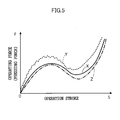
- Fig. 5 is a graph comparing the operational feeling (i.e., the relationship between the force F pressing the switch 14 and the operation stroke S) of the switch operating mechanism 10 of the present embodiment with those of the conventional mechanisms.
- a line X relates to the switch operating mechanism 10 of the present embodiment and a line Y relates to the conventional switch mechanism 50 with a hinge-type operating knob 54.
- a line Z relates to the switch operating mechanism 60, which only uses pusher 56 to press a switch instead of using an operating knob.
- the switch operating mechanism 60 which is constructed to press by only using the pusher 56 without the usage of an operating knob, provides the ideal characteristic of the operational feeling (i.e., the relationship between the force F pressing the switch 14 and the operation stroke S).
- the operating knob 54 is cranked to operate the switch 14 and is supported by a spindle 52 provided at a lower position than the switch 14. Since the front end 54A of the operating knob 54 (the portion at which the operating knob 54 presses the pusher 56) moves along an arcuate path around the spindle 52, noises occur in the pressing force F (i.e., components of the pressing force act not only in the axial direction of the pusher 56 but also in the direction perpendicular thereto), and the operational feeling of the operating knob 54 is impaired as shown by the line Y (i.e., the characteristic shown by the line Y differs significantly from that shown by the line Z).
- the line Y i.e., the characteristic shown by the line Y differs significantly from that shown by the line Z.
- the operational feeling of the operating knob 20 can be much closer to the ideal characteristic (i.e., the characteristic shown by the line Z).
- the switch 14 of the circuit board 12 is disposed between the first and the second pressing arms 28 and 30 of the pusher 24. Accordingly, a guide mechanism for guiding the pusher 24 may be provided along the base 26 of the pusher 24 (on the base 26 side of the pusher). That is, it is not necessary to provide the guide mechanism above the circuit board 12, whereby the space above the circuit board 12 can be used effectively.
- the switch operating mechanism of the present invention has excellent effects such as providing an operating knob that has an improved operational feeling, and at the same time, meets the demand for effective use of the space above the circuit board.
Abstract
Description
- The present invention relates to a switch operating mechanism in which an operator turns a switch on and/or off by pressing the switch provided at a circuit board.
- Some automobile steering wheels are equipped with, for example, a switch for shifting gears. Among such switch operating mechanisms, there is a type which is arranged to activate the switch by moving the operating knob upward so that the switch can be operated while an operator is holding the steering wheel.
- A
switch operating mechanism 50 of this type includes acircuit board 12 with a switch 14 (a contact member held by rubber) and anoperating knob 54 that is supported by aspindle 52 so as to rotate about thespindle 52, which is provided at a lower position than theswitch 14 as schematically illustrated in Fig. 4B. When the operator moves theoperating knob 54 upward, theoperating knob 54 rotates about thespindle 52, and afront end 54A of theoperating knob 54 presses apusher 56 downward, thereby turning theswitch 14 on and/or off (i.e., a hinge-type operating knob). - However, the conventional
switch operating mechanism 50 has some drawbacks. Theoperating knob 54 is cranked to operate theswitch 14. Further, since theswitch operating mechanism 50 is supported by a spindle provided at a lower position than theswitch 14, thefront end 54A of the operating knob 54 (the portion of the operating knob that presses the pusher 56) moves along an arcuate path around thespindle 52. Components of the pressing force act not only in an axial direction of thepusher 56 but also in a direction perpendicular thereto, and the relationship between a force F pressing theswitch 14 and an operation stroke S deteriorates. As a result, operational feeling of theoperating knob 54 is impaired. Moreover, there is a demand for using the space above thecircuit board 12 effectively. However, a guide mechanism for guiding thepusher 56 occupies the space above thecircuit board 12, making it impossible to use the space for other purposes in other ways. - In view of the aforementioned facts, an object of the present invention is to provide a switch operating mechanism, which has an operating knob that gives the operator an improved operational feeling and, at the same time, meets the demand for effective use of the space above the circuit board.
- A first aspect of the present invention is a switch operating mechanism for turning a switch on and/or off by pressing the switch, which is provided at a circuit board, the mechanism comprising: an operating knob, which has a front end and a back end and is rotatably supported by a spindle that is provided at a lower position than the switch; and a pusher having a base, a first pressing arm, and a second pressing arm, the first pressing arm and the second pressing arm extending parallel to each other from both ends of the base in a direction perpendicular to an axial direction of the base such that the pusher has a substantial U-shape when seen in side view, wherein the switch of the circuit board is disposed between the first and the second pressing arms of the pusher, the first pressing arm being positioned directly above the switch and able to press the same; the operating knob is disposed such that the front end thereof is disposed between the circuit board and the second pressing arm so that the front end is able to press the second pressing arm; and when the back end of the operating knob is moved upward, the front end thereof moves the second pressing arm of the pusher downward, whereby the pusher moves linearly along a direction perpendicular to the plane of the circuit board, and the first pressing arm of the pusher presses the switch to turn the switch on and/or off.
- In the switch operating mechanism of the first aspect of the present invention, when the operator moves the operating knob upward, the operating knob rotates and the front end thereof moves the second pressing arm of the pusher downward. Thus, the pusher moves linearly along the direction perpendicular to the plane of the circuit board, and the first pressing arm of the pusher presses the switch to turn the switch on and/or off.
- In the switch operating mechanism, the operating knob is supported by the spindle, which is disposed at a lower position than the switch, and the pusher is formed in a substantial U-shape when seen in side view. Accordingly, even if the front end of the operating knob (the portion of the operating knob that presses the second pressing arm of the pusher) moves along an arcuate path around the spindle, the linear movement of the pusher presses and activates the switch. Thus, operational feeling of the operating knob, i.e., a relationship between a force pressing the switch and an operation stroke can be much closer to an ideal relationship. Further, in the switch operating mechanism, the switch of the circuit board is disposed between the first and the second pressing arms of the pusher. Accordingly, a guide mechanism for guiding the pusher may be provided along the base of the pusher (at the base side of the pusher). In other words, it is not necessary to provide the guide mechanism above the circuit board, whereby the space above the circuit board can be used effectively.
- A second aspect of the present invention is a switch operating mechanism provided in a vehicle, for turning a switch on and/or off by pressing the switch provided at a circuit board, the mechanism comprising: an operating knob, which has a front end and a back end and is rotatably supported by a spindle that is provided at a lower position than the switch; and a pusher having a base, a first pressing arm, and a second pressing arm, the first pressing arm and the second pressing arm extending parallel to each other from both ends of the base in a direction perpendicular to an axial direction of the base such that the pusher has a substantial U-shape when seen in side view, wherein the switch of the circuit board is disposed between the first and the second pressing arms of the pusher, the first pressing arm being positioned directly above the switch and able to press the same; the operating knob is disposed such that the front end thereof is disposed between the circuit board and the second pressing arm so that the front end is able to press the second pressing arm; and when the back end of the operating knob is moved upward, the front end thereof moves the second pressing arm of the pusher downward, whereby the pusher moves linearly along a direction perpendicular to the plane of the circuit board, and the first pressing arm of the pusher presses the switch to turn the switch on and/or off.
- A third aspect of the present invention is a method of manufacturing a switch operating mechanism for turning a switch on and/or off by pressing the switch, the method comprising the steps of: a. manufacturing a operating knob having a front end and a back end; b. manufacturing a pusher having a base, a first pressing arm, and a second pressing arm, the first pressing arm and the second pressing arm extending parallel to each other from both ends of the base in a direction perpendicular to an axial direction of the base such that the pusher has a substantial U-shape when seen in side view; c. mounting the operating knob to a spindle provided at a lower position than the switch so as to rotate about the spindle; and d. disposing the switch and the front end of the operating knob between the first pressing arm and the second pressing arm.
-
- Fig. 1 is a sectional view showing a structure of a switch operating mechanism of an embodiment of the present invention.
- Fig. 2 is a schematic perspective view showing the structure of the switch operating mechanism of the embodiment of the present invention.
- Fig. 3 is a front view of a steering wheel equipped with the switch operating mechanism of the embodiment of the present invention.
- Fig. 4A is a diagram schematically showing the switch operating mechanism of the embodiment of the present invention.
- Fig. 4B is a diagram schematically showing a conventional switch operating mechanism with a hinge-type operating knob.
- Fig. 4C is a diagram schematically showing a switch operating mechanism, which only uses a pusher to press a switch instead of using an operating knob.
- Fig. 5 is a graph showing a relationship between a pressing force and an operation stroke, used for comparing an operational feeling of an operating knob of the switch operating mechanism of the present invention with those of conventional mechanisms.
-
- A
switch operating mechanism 10 relating to an embodiment of the present invention is provided at, for example, a steering wheel in an automobile as shown in Fig. 3. Theswitch operating mechanism 10 is used as an operating mechanism for shifting gears. - Fig. 1 is a sectional view, and Fig. 2 is a schematic perspective view, of the structure of the
switch operating mechanism 10. - The
switch operating mechanism 10 includes a circuit board (i.e., a PC board) 12. Thecircuit board 12 has a predetermined switch circuit formed thereon, and is provided with aswitch 14. Acontact member 18 of theswitch 14 is held by arubber holding sheet 16 which has a predetermined elasticity. When thecontact member 18 is pressed on thecircuit board 12 against the elastic force of therubber holding sheet 16, the electric circuit is closed and/or opened (i.e., turned on and/or off). - An
operating knob 20 is provided at a lateral side of thecircuit board 12. Theoperating knob 20 is supported by aspindle 22, which is provided at a lower position than theswitch 14 of thecircuit board 12 so that theoperating knob 20 can rotate about thespindle 22. - The
switch operating mechanism 10 further includes apusher 24. Thepusher 24 has abase 26, a firstpressing arm 28, and a secondpressing arm 30. The firstpressing arm 28 and the secondpressing arm 30 extend parallel to each other from both ends of thebase 26 in the direction perpendicular to the axial direction of thebase 26. Namely, thepusher 24 has a substantial U-shape when seen in side view. Thepusher 24 is supported by aguide 32, which is provided to stand vertically, so as to slide in the axial direction of thebase 26. - The
switch 14 of thecircuit board 12 is disposed between the first and the second pressingarms pusher 24. The firstpressing arm 28 is positioned directly above theswitch 14 and is able to press the same. Thefront end 20A of theoperating knob 20 is disposed between thecircuit board 12 and the secondpressing arm 30 so that thefront end 20A is able to press the secondpressing arm 30. Therefore, when theoperating knob 20 is moved upward, thefront end 20A moves the secondpressing arm 30 downward. Thepusher 24 is moved linearly along the direction perpendicular to the plane of thecircuit board 12, and theswitch 14 is turned on and/or off by the firstpressing arm 28. - Since the
operating knob 20 is supported by thespindle 22, which is disposed at a lower position than theswitch 14, theswitch 14 can be pressed and activated by the linear movement of thepusher 24, which is formed in a substantial U-shape when seen in side view, even if thefront end 20A (the portion of the operating knob that presses the second pressing arm 30) moves around thespindle 22 along an arcuate path. Thus, the operational feeling of theoperating knob 20, i.e., a relationship between a force pressing theswitch 14 and an operation stroke can be much closer to an ideal relationship. - The
switch operating mechanism 10 of the present embodiment and conventional mechanisms to be compared therewith are illustrated in Figs. 4A through 4C. Fig. 4A shows theswitch operating mechanism 10 of the present embodiment. Fig. 4B shows a conventionalswitch operating mechanism 50 with a hinge-type operating knob 54. Fig. 4C shows aswitch operating mechanism 60, which only usespusher 56 to press a switch instead of using an operating knob. - Fig. 5 is a graph comparing the operational feeling (i.e., the relationship between the force F pressing the
switch 14 and the operation stroke S) of theswitch operating mechanism 10 of the present embodiment with those of the conventional mechanisms. A line X relates to theswitch operating mechanism 10 of the present embodiment and a line Y relates to theconventional switch mechanism 50 with a hinge-type operating knob 54. a line Z relates to theswitch operating mechanism 60, which only usespusher 56 to press a switch instead of using an operating knob. - As the line Z shows, the
switch operating mechanism 60, which is constructed to press by only using thepusher 56 without the usage of an operating knob, provides the ideal characteristic of the operational feeling (i.e., the relationship between the force F pressing theswitch 14 and the operation stroke S). - In the conventional
switch operating mechanism 50 with a hinge-type operating knob 54, the operatingknob 54 is cranked to operate theswitch 14 and is supported by aspindle 52 provided at a lower position than theswitch 14. Since thefront end 54A of the operating knob 54 (the portion at which the operatingknob 54 presses the pusher 56) moves along an arcuate path around thespindle 52, noises occur in the pressing force F (i.e., components of the pressing force act not only in the axial direction of thepusher 56 but also in the direction perpendicular thereto), and the operational feeling of the operatingknob 54 is impaired as shown by the line Y (i.e., the characteristic shown by the line Y differs significantly from that shown by the line Z). - In the
switch operating mechanism 10 of the present embodiment, the linear movement of thepusher 24, which is formed in a substantial U-shape when seen in side view, presses and activates theswitch 14. Thus, as the line X shows, the operational feeling of the operatingknob 20 can be much closer to the ideal characteristic (i.e., the characteristic shown by the line Z). - Further, in the
switch operating mechanism 10, theswitch 14 of thecircuit board 12 is disposed between the first and the secondpressing arms pusher 24. Accordingly, a guide mechanism for guiding thepusher 24 may be provided along thebase 26 of the pusher 24 (on the base 26 side of the pusher). That is, it is not necessary to provide the guide mechanism above thecircuit board 12, whereby the space above thecircuit board 12 can be used effectively. - As described above, the switch operating mechanism of the present invention has excellent effects such as providing an operating knob that has an improved operational feeling, and at the same time, meets the demand for effective use of the space above the circuit board.
- The features disclosed in the foregoing description, in the claims and/or in the accompanying drawings may, both separately and in any combination thereof, be material for realising the invention in diverse forms thereof.
Claims (15)
- A switch operating mechanism for turning a switch on and/or off by pressing the switch, which is provided at a circuit board, the mechanism comprising:an operating knob, which has a front end and a back end and is rotatably supported by a spindle that is provided at a lower position than the switch; anda pusher having a base, a first pressing arm, and a second pressing arm, the first pressing arm and the second pressing arm extending parallel to each other from both ends of the base in a direction perpendicular to an axial direction of the base such that the pusher has a substantial U-shape when seen in side view, whereinthe switch of the circuit board is disposed between the first and the second pressing arms of the pusher, the first pressing arm being positioned directly above the switch and able to press the same;the operating knob is disposed such that the front end thereof is disposed between the circuit board and the second pressing arm so that the front end is able to press the second pressing arm; andwhen the back end of the operating knob is moved upward, the front end thereof moves the second pressing arm of the pusher downward, whereby the pusher moves linearly along a direction perpendicular to the plane of the circuit board, and the first pressing arm of the pusher presses the switch to turn the switch on and/or off.
- The mechanism according to claim 1, wherein the spindle is disposed at a higher position than the front end of the operating knob.
- The mechanism according to claim 1, further comprising a guide mechanism provided parallel to the pusher in an axial direction thereof, wherein the pusher is slidably supported by the guide mechanism so as to move linearly along the direction perpendicular to the plane of the circuit board.
- The mechanism according to claim 3, which is provided in a vehicle.
- The mechanism according to claim 3, which is provided at a steering wheel in a vehicle.
- The mechanism according to claim 5, which is used for shifting gears while the vehicle is driven.
- A switch operating mechanism provided in a vehicle, for turning a switch on and/or off by pressing the switch provided at a circuit board, the mechanism comprising:an operating knob, which has a front end and a back end and is rotatably supported by a spindle that is provided at a lower position than the switch; anda pusher having a base, a first pressing arm, and a second pressing arm, the first pressing arm and the second pressing arm extending parallel to each other from both ends of the base in a direction perpendicular to an axial direction of the base such that the pusher has a substantial U-shape when seen in side view, whereinthe switch of the circuit board is disposed between the first and the second pressing arms of the pusher, the first pressing arm being positioned directly above the switch and able to press the same;the operating knob is disposed such that the front end thereof is disposed between the circuit board and the second pressing arm so that the front end is able to press the second pressing arm; andwhen the back end of the operating knob is moved upward, the front end thereof moves the second pressing arm of the pusher downward, whereby the pusher moves linearly along a direction perpendicular to the plane of the circuit board, and the first pressing arm of the pusher presses the switch to turn the switch on and/or off.
- The mechanism according to claim 7, wherein the spindle is disposed at a higher position than the front end of the operating knob.
- The mechanism according to claim 7, further comprising a guide mechanism provided parallel to the pusher in an axial direction thereof, wherein the pusher is slidably supported by the guide mechanism so as to move linearly along the direction perpendicular to the plane of the circuit board.
- The mechanism according to claim 9, which is provided at a steering wheel in a vehicle.
- The mechanism according to claim 10, which is used for shifting gears while the vehicle is driven.
- A method of manufacturing a switch operating mechanism for turning a switch on and/or off by pressing the switch, the method comprising the steps of:a. manufacturing a operating knob having a front end and a back end;b. manufacturing a pusher having a base, a first pressing arm, and a second pressing arm, the first pressing arm and the second pressing arm extending parallel to each other from both ends of the base in a direction perpendicular to an axial direction of the base such that the pusher has a substantial U-shape when seen in side view;c. mounting the operating knob to a spindle provided at a lower position than the switch so as to rotate about the spindle; andd. disposing the switch and the front end of the operating knob between the first pressing arm and the second pressing arm.
- The method according to claim 12, wherein the spindle is disposed at a higher position than the front end of the operating knob.
- The method according to claim 13, wherein the switch is disposed directly below the first pressing arm.
- The method according to claim 14, further comprising the step for manufacturing a guide mechanism which slidably supports the pusher in an axial direction of the pusher.
Applications Claiming Priority (2)
| Application Number | Priority Date | Filing Date | Title |
|---|---|---|---|
| JP2001307466 | 2001-10-03 | ||
| JP2001307466A JP3875530B2 (en) | 2001-10-03 | 2001-10-03 | Switch operation mechanism |
Publications (3)
| Publication Number | Publication Date |
|---|---|
| EP1300859A2 true EP1300859A2 (en) | 2003-04-09 |
| EP1300859A3 EP1300859A3 (en) | 2004-12-15 |
| EP1300859B1 EP1300859B1 (en) | 2010-09-08 |
Family
ID=19126924
Family Applications (1)
| Application Number | Title | Priority Date | Filing Date |
|---|---|---|---|
| EP02022122A Expired - Fee Related EP1300859B1 (en) | 2001-10-03 | 2002-10-02 | Switch operating mechanism |
Country Status (4)
| Country | Link |
|---|---|
| US (1) | US6796202B2 (en) |
| EP (1) | EP1300859B1 (en) |
| JP (1) | JP3875530B2 (en) |
| DE (1) | DE60237571D1 (en) |
Cited By (3)
| Publication number | Priority date | Publication date | Assignee | Title |
|---|---|---|---|---|
| EP1310968A2 (en) † | 2001-11-07 | 2003-05-14 | Kabushiki Kaisha Tokai Rika Denki Seisakusho | Switch apparatus |
| DE102009019304A1 (en) * | 2009-04-24 | 2010-11-11 | Takata-Petri Ag | Circuit arrangement for steering wheel of motor vehicle, has circuit element for triggering horn signal which stands in communication connection with horn signal generating unit of motor vehicle by circuit arrangement |
| FR2975514A1 (en) * | 2011-05-16 | 2012-11-23 | Peugeot Citroen Automobiles Sa | Push-button assembly for steering wheel of car, has control unit actuated by push-button, switch offset from push-button, and another control unit actuating switch in response to operation of former control unit |
Families Citing this family (9)
| Publication number | Priority date | Publication date | Assignee | Title |
|---|---|---|---|---|
| DE20116306U1 (en) * | 2001-10-05 | 2002-02-14 | Trw Automotive Safety Sys Gmbh | vehicle steering wheel |
| US7762159B2 (en) * | 2002-08-28 | 2010-07-27 | Alps Electric Co., Ltd. | Steering switch for vehicle |
| KR100569951B1 (en) * | 2003-10-09 | 2006-04-10 | 현대자동차주식회사 | Steering wheel remocone switch button for vehicle |
| JP2005140242A (en) * | 2003-11-06 | 2005-06-02 | Iseki & Co Ltd | Shift control device for working vehicle |
| JP4184926B2 (en) * | 2003-11-10 | 2008-11-19 | アルプス電気株式会社 | Steering switch device |
| US7296490B2 (en) * | 2004-12-23 | 2007-11-20 | Chrysler Llc | Switch assembly for selecting among plurality of shift schedules on an electronically controlled transmission |
| CN104648464A (en) * | 2015-01-21 | 2015-05-27 | 天合汽车科技(上海)有限公司 | Steering wheel with horn press-sounding mechanism |
| FR3067133B1 (en) * | 2017-06-02 | 2020-10-30 | Valeo Schalter & Sensoren Gmbh | CONTROL DEVICE AND STEERING WHEEL EQUIPPED WITH SUCH A DEVICE, ESPECIALLY FOR MOTOR VEHICLES |
| JP7038325B2 (en) * | 2018-06-29 | 2022-03-18 | パナソニックIpマネジメント株式会社 | Switch device, mobile |
Citations (2)
| Publication number | Priority date | Publication date | Assignee | Title |
|---|---|---|---|---|
| GB1053962A (en) * | 1900-01-01 | |||
| US6054655A (en) * | 1998-05-11 | 2000-04-25 | Eaton Corporation | Power window switch |
Family Cites Families (7)
| Publication number | Priority date | Publication date | Assignee | Title |
|---|---|---|---|---|
| US2939447A (en) * | 1956-08-08 | 1960-06-07 | Ford Motor Co | Push button gear shift with neutral start button |
| US3665130A (en) * | 1970-10-28 | 1972-05-23 | Tokai Rika Co Ltd | Hazard warning switch for automotive vehicles |
| US3683144A (en) * | 1971-03-04 | 1972-08-08 | Columbus Electric Mfg Co | Non-snap-acting switch devices with s-shaped contact spring blade |
| US4230919A (en) * | 1978-03-13 | 1980-10-28 | Schantz Spencer C | Snap acting switch |
| US4877925A (en) * | 1987-10-23 | 1989-10-31 | Clarion Co., Ltd. | Multi-stage push button switch device |
| US5219070A (en) * | 1991-07-12 | 1993-06-15 | Westinghouse Electric Corp. | Lockable rotary handle operator for circuit breaker |
| JP3764290B2 (en) * | 1999-01-13 | 2006-04-05 | 株式会社東海理化電機製作所 | Lever switch |
-
2001
- 2001-10-03 JP JP2001307466A patent/JP3875530B2/en not_active Expired - Fee Related
-
2002
- 2002-10-02 EP EP02022122A patent/EP1300859B1/en not_active Expired - Fee Related
- 2002-10-02 DE DE60237571T patent/DE60237571D1/en not_active Expired - Lifetime
- 2002-10-02 US US10/261,770 patent/US6796202B2/en not_active Expired - Lifetime
Patent Citations (2)
| Publication number | Priority date | Publication date | Assignee | Title |
|---|---|---|---|---|
| GB1053962A (en) * | 1900-01-01 | |||
| US6054655A (en) * | 1998-05-11 | 2000-04-25 | Eaton Corporation | Power window switch |
Cited By (4)
| Publication number | Priority date | Publication date | Assignee | Title |
|---|---|---|---|---|
| EP1310968A2 (en) † | 2001-11-07 | 2003-05-14 | Kabushiki Kaisha Tokai Rika Denki Seisakusho | Switch apparatus |
| EP1310968B2 (en) † | 2001-11-07 | 2010-09-29 | Kabushiki Kaisha Tokai Rika Denki Seisakusho | Switch apparatus |
| DE102009019304A1 (en) * | 2009-04-24 | 2010-11-11 | Takata-Petri Ag | Circuit arrangement for steering wheel of motor vehicle, has circuit element for triggering horn signal which stands in communication connection with horn signal generating unit of motor vehicle by circuit arrangement |
| FR2975514A1 (en) * | 2011-05-16 | 2012-11-23 | Peugeot Citroen Automobiles Sa | Push-button assembly for steering wheel of car, has control unit actuated by push-button, switch offset from push-button, and another control unit actuating switch in response to operation of former control unit |
Also Published As
| Publication number | Publication date |
|---|---|
| EP1300859B1 (en) | 2010-09-08 |
| US6796202B2 (en) | 2004-09-28 |
| DE60237571D1 (en) | 2010-10-21 |
| US20030061896A1 (en) | 2003-04-03 |
| EP1300859A3 (en) | 2004-12-15 |
| JP2003115238A (en) | 2003-04-18 |
| JP3875530B2 (en) | 2007-01-31 |
Similar Documents
| Publication | Publication Date | Title |
|---|---|---|
| EP1760742B1 (en) | Switch device and steering switch apparatus equipped with the switch device | |
| US6796202B2 (en) | Switch operating mechanism | |
| EP1975956B1 (en) | Trigger Switch | |
| JP5893753B2 (en) | Reset device for automobile steering column switch system and automobile | |
| WO2018123223A1 (en) | Contact structure for switch, trigger switch and electric power tool | |
| US5117076A (en) | Quieting device for keytop leveling mechanisms | |
| US7488907B2 (en) | Lever switch device | |
| JP2002283871A (en) | Accelerator pedal device | |
| JP4620636B2 (en) | Rotation operation type output device | |
| JP4575849B2 (en) | Shift switch | |
| JP2010113978A (en) | Push type switch for automobile interior | |
| JP4030735B2 (en) | Switch device | |
| JP2003127764A (en) | Cancel structure of combination switch | |
| JP4899644B2 (en) | Electronic device switch mechanism | |
| JP2008130497A (en) | Switching device | |
| US9902316B2 (en) | Steering-column switch unit for a motor vehicle, and motor vehicle having a steering-column switch unit | |
| KR100888366B1 (en) | Seat switch for car | |
| EP1049121A2 (en) | Sliding operation type switch apparatus | |
| JP3076171B2 (en) | Shifting device for automatic transmission | |
| US20050061639A1 (en) | Switch stabilizer | |
| JP4528697B2 (en) | Switch device | |
| JP2010205684A (en) | Switching arrangement | |
| JP2605566Y2 (en) | Shifting device for automatic transmission | |
| JP2004206926A (en) | Switchgear | |
| JP4810454B2 (en) | Lever switch |
Legal Events
| Date | Code | Title | Description |
|---|---|---|---|
| PUAI | Public reference made under article 153(3) epc to a published international application that has entered the european phase |
Free format text: ORIGINAL CODE: 0009012 |
|
| AK | Designated contracting states |
Kind code of ref document: A2 Designated state(s): AT BE BG CH CY CZ DE DK EE ES FI FR GB GR IE IT LI LU MC NL PT SE SK TR |
|
| AX | Request for extension of the european patent |
Extension state: AL LT LV MK RO SI |
|
| PUAL | Search report despatched |
Free format text: ORIGINAL CODE: 0009013 |
|
| AK | Designated contracting states |
Kind code of ref document: A3 Designated state(s): AT BE BG CH CY CZ DE DK EE ES FI FR GB GR IE IT LI LU MC NL PT SE SK TR |
|
| AX | Request for extension of the european patent |
Extension state: AL LT LV MK RO SI |
|
| 17P | Request for examination filed |
Effective date: 20050125 |
|
| AKX | Designation fees paid |
Designated state(s): DE FR GB SE |
|
| GRAP | Despatch of communication of intention to grant a patent |
Free format text: ORIGINAL CODE: EPIDOSNIGR1 |
|
| RIC1 | Information provided on ipc code assigned before grant |
Ipc: H01H 21/24 20060101AFI20100421BHEP |
|
| RIN1 | Information on inventor provided before grant (corrected) |
Inventor name: WATANABE, SHINJI,C/O KABUSHIKI KAISHA TOKAI-RIKA-D Inventor name: MIYAKO, MAMORU,C/O KABUSHIKI KAISHA TOKAI-RIKA-DEN Inventor name: TAKAI, TOSHIHITO,C/O KABUSHIKI KAISHA TOKAI-RIKA-D |
|
| RAP1 | Party data changed (applicant data changed or rights of an application transferred) |
Owner name: KABUSHIKI KAISHA TOKAI RIKA DENKI SEISAKUSHO |
|
| GRAS | Grant fee paid |
Free format text: ORIGINAL CODE: EPIDOSNIGR3 |
|
| GRAA | (expected) grant |
Free format text: ORIGINAL CODE: 0009210 |
|
| AK | Designated contracting states |
Kind code of ref document: B1 Designated state(s): DE FR GB SE |
|
| REG | Reference to a national code |
Ref country code: GB Ref legal event code: FG4D |
|
| REF | Corresponds to: |
Ref document number: 60237571 Country of ref document: DE Date of ref document: 20101021 Kind code of ref document: P |
|
| REG | Reference to a national code |
Ref country code: SE Ref legal event code: TRGR |
|
| PLBE | No opposition filed within time limit |
Free format text: ORIGINAL CODE: 0009261 |
|
| STAA | Information on the status of an ep patent application or granted ep patent |
Free format text: STATUS: NO OPPOSITION FILED WITHIN TIME LIMIT |
|
| 26N | No opposition filed |
Effective date: 20110609 |
|
| REG | Reference to a national code |
Ref country code: DE Ref legal event code: R097 Ref document number: 60237571 Country of ref document: DE Effective date: 20110609 |
|
| REG | Reference to a national code |
Ref country code: FR Ref legal event code: PLFP Year of fee payment: 14 |
|
| PGFP | Annual fee paid to national office [announced via postgrant information from national office to epo] |
Ref country code: GB Payment date: 20150930 Year of fee payment: 14 |
|
| PGFP | Annual fee paid to national office [announced via postgrant information from national office to epo] |
Ref country code: FR Payment date: 20150908 Year of fee payment: 14 |
|
| PGFP | Annual fee paid to national office [announced via postgrant information from national office to epo] |
Ref country code: DE Payment date: 20150929 Year of fee payment: 14 |
|
| PGFP | Annual fee paid to national office [announced via postgrant information from national office to epo] |
Ref country code: SE Payment date: 20151013 Year of fee payment: 14 |
|
| REG | Reference to a national code |
Ref country code: DE Ref legal event code: R119 Ref document number: 60237571 Country of ref document: DE |
|
| GBPC | Gb: european patent ceased through non-payment of renewal fee |
Effective date: 20161002 |
|
| REG | Reference to a national code |
Ref country code: FR Ref legal event code: ST Effective date: 20170630 |
|
| PG25 | Lapsed in a contracting state [announced via postgrant information from national office to epo] |
Ref country code: FR Free format text: LAPSE BECAUSE OF NON-PAYMENT OF DUE FEES Effective date: 20161102 Ref country code: GB Free format text: LAPSE BECAUSE OF NON-PAYMENT OF DUE FEES Effective date: 20161002 Ref country code: DE Free format text: LAPSE BECAUSE OF NON-PAYMENT OF DUE FEES Effective date: 20170503 |
|
| PG25 | Lapsed in a contracting state [announced via postgrant information from national office to epo] |
Ref country code: SE Free format text: LAPSE BECAUSE OF NON-PAYMENT OF DUE FEES Effective date: 20161003 |