EP1300594B1 - Centrifugal slurry pump - Google Patents
Centrifugal slurry pump Download PDFInfo
- Publication number
- EP1300594B1 EP1300594B1 EP20020020035 EP02020035A EP1300594B1 EP 1300594 B1 EP1300594 B1 EP 1300594B1 EP 20020020035 EP20020020035 EP 20020020035 EP 02020035 A EP02020035 A EP 02020035A EP 1300594 B1 EP1300594 B1 EP 1300594B1
- Authority
- EP
- European Patent Office
- Prior art keywords
- cutting plate
- waste water
- pump housing
- pump
- cutting
- Prior art date
- Legal status (The legal status is an assumption and is not a legal conclusion. Google has not performed a legal analysis and makes no representation as to the accuracy of the status listed.)
- Expired - Lifetime
Links
Images

Classifications
-
- F—MECHANICAL ENGINEERING; LIGHTING; HEATING; WEAPONS; BLASTING
- F04—POSITIVE - DISPLACEMENT MACHINES FOR LIQUIDS; PUMPS FOR LIQUIDS OR ELASTIC FLUIDS
- F04D—NON-POSITIVE-DISPLACEMENT PUMPS
- F04D7/00—Pumps adapted for handling specific fluids, e.g. by selection of specific materials for pumps or pump parts
- F04D7/02—Pumps adapted for handling specific fluids, e.g. by selection of specific materials for pumps or pump parts of centrifugal type
- F04D7/04—Pumps adapted for handling specific fluids, e.g. by selection of specific materials for pumps or pump parts of centrifugal type the fluids being viscous or non-homogenous
- F04D7/045—Pumps adapted for handling specific fluids, e.g. by selection of specific materials for pumps or pump parts of centrifugal type the fluids being viscous or non-homogenous with means for comminuting, mixing stirring or otherwise treating
Definitions
- the invention relates to a waste water centrifugal pump according to the preamble of patent claim 1, as in DE-A-198 34 815 shown.
- Smaller size centrifugal pumps which are mounted in collecting wells and pump out incoming waste water containing more or less large proportions of solid matter, have in their suction area a cutting mechanism which consists of a cutting plate which is fixedly attached to the pump housing and has a plurality of cutting teeth, and off a rotating cutting body, which is fixed to the pump shaft and a plurality of counter-cutting teeth, which cooperate with the cutting teeth of the cutting plate consists exists. Because such reapers undergo relatively large wear, they often have to be replaced. The replacement is cumbersome and time consuming, which is due to the unfavorable mounting structure of the cutting unit on the pump housing. Thus, it is necessary to partially or completely disassemble the pump housing to remove the cutting plate and then the cutting body can.
- the object of the invention is to improve an initially mentioned wastewater centrifugal pump to the effect that the cutting unit can be quickly and easily replaced and securely fastened without disassembly of the pump housing is required to replace in particular the cutting plate.
- the cutting plate is provided at its outer periphery with a plurality of recesses and the pump housing has according to the number of these recesses a plurality of radially projecting to the axis of rotation of the pump shaft and the edge of the cutting plate between these recesses engaging behind holding projections, wherein the edge between the retaining projections and the pump housing can be clamped.
- a simple embodiment for the clamping of the cutting plate is that the edge of the cutting plate between the recesses is provided with a plurality of clamping cam, with the aid of which the cutting plate is clamped between the pump housing and the holding projections.
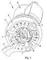
- a wastewater pump unit 1 which is composed of a wastewater centrifugal pump 2 and an electric motor 3 to the drive.
- the Abwassernikelpumpe comprises a pump housing 4 with a suction area 5, an outlet 6 and a plurality of Abstützweg 7 7. With the support feet, the unit 1 is supported on a bottom surface, a storage area or the like, wherein the support feet have a sufficient height to the entry oflocked agondem wastewater to allow in the intake 5 of the pump 2.
- a cutting mechanism which consists of a cutting plate 8 with preferably two cutting teeth 9 and a cutting body 10 with preferably two counter-cutting teeth 11.
- the cutting plate 8 is fixedly mounted on the outside of the pump housing 4, while the cutting body 10 is screwed tightly to the front end 12 of the rotating pump shaft 13.
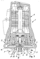
- the cutting body 10 is supported in the case shown on the pump impeller 14 from ( Fig. 3 ), which in turn is rotationally fixed and fixed to an axial stop, such as a collar or a shoulder, adjacent to the pump shaft 13.
- a bayonet connection is provided, which is best in the Figures 2 and 3 can be seen.
- the cutting plate 8 has a central hole 15, through which the cutting body 10 in its mounted state according to the FIGS. 1 and 3 extends such that a sufficiently large inlet cross section for the effluent to be removed remains and the cutting teeth 9 of the cutting plate 8 and the counter cutting teeth 11 of the cutting body 10 cooperate to reduce solids in the wastewater in a conventional manner.
- the bayonet connection is formed by a plurality of recesses 16 on the outer circumference of the cutting plate 8 and by according to the number of these recesses the same number of retaining projections 17 on the pump housing 4, wherein the retaining projections project radially to the axis of rotation 18 of the pump shaft 13.
- the projections 17 form between them and their facing inner edge region of the pump housing 4 at a distance which corresponds approximately to the thickness of the outer edge of the cutting plate 8 between the recesses 16.
- the corresponding edge portions 8a of the cutting plate 8 can be engaged behind between the recesses 16 of the retaining projections 17 when the cutting plate is rotated after its axial insertion.
- the cutting plate 8 is provided on its outside, ie on the side facing the holding projections 17, with a plurality of clamping cam 19.
- three clamping cams 19 are provided which are located on the edge sections 8a between the recesses 16 of the cutting plate 8.
- the clamping cam 19 are formed, for example, comma-shaped ( Fig. 2 ); but they can also be wedge-shaped.
- the provision of the clamping cam 19 ensures that the cutting plate 8 is clamped wobble-free and self-locking on the pump housing 4.
- the pump housing 4 is provided with an annular recess 20 adjacent to the suction region 5, which receives the edge portions 8a of the cutting plate 8.
- mounting holes 21 which are provided in the edge portions 8a and in which a corresponding tool engages to mount the cutting plate 8 by turning and disassemble.
- a locking screw 22 may be provided.
- This locking screw is advantageously screwed into one of the holding projections 17 and presses the cutting plate, ie its corresponding peripheral edge portion 8a in the recess, against the pump housing 4.
- the cutting plate or the pump housing if the cutting plate has a through hole, a recess (not shown) have, in which engages the locking screw. Since the pump housing 4 is usually provided with Abstützfeld H 7, it is advisable to form the Abstützfozoe so that they simultaneously form the retaining projections 17, as in the FIGS. 1 and 3 is shown.
Landscapes
- Engineering & Computer Science (AREA)
- Mechanical Engineering (AREA)
- General Engineering & Computer Science (AREA)
- Structures Of Non-Positive Displacement Pumps (AREA)
Description
Die Erfindung geht aus von einer Abwasserkreiselpumpe gemäß dem Oberbegriff des Patentanspruchs 1, wie in
Abwasserkreiselpumpen kleinerer Baugröße, die in Sammelbrunnen montiert sind und dort einlaufendes Abwasser, das mehr oder weniger große Feststoffanteile enthält, abpumpen, weisen in ihrem Ansaugbereich ein Schneidwerk auf, das aus einer Schneidplatte, die stationär am Pumpengehäuse befestigt ist und mehrere Schneidzähne aufweist, und aus einem rotierenden Schneidkörper, der an der Pumpenwelle befestigt ist und mehrere Gegenschneidzähne, die mit den Schneidzähnen der Schneidplatte zusammenwirken, aufweist, besteht. Weil solche Schneidwerke eine relativ große Abnutzung erfahren, müssen sie oft ausgewechselt werden. Das Auswechseln ist jedoch umständlich und zeitraubend, was auf die ungünstige Montagekonstruktion des Schneidwerkes an dem Pumpengehäuse zurückzuführen ist. So ist es erforderlich, das Pumpengehäuse teilweise oder vollständig zu demontieren, um die Schneidplatte und anschließend den Schneidkörper entfernen zu können. Die gesamte Montage eines neuen Schneidwerkes erfolgt dann mit den gleichen Nachteilen in umgekehrter Reihenfolge. Außerdem besteht bei ungenügend festgeschraubter Schneidplatte die Gefahr, dass die Schrauben aufgrund der hohen Drehmomentbelastung der Schneidplat+e abgeschert werden, so dass sich die Schneidplatte aus ihrer Befestigung löst.Smaller size centrifugal pumps, which are mounted in collecting wells and pump out incoming waste water containing more or less large proportions of solid matter, have in their suction area a cutting mechanism which consists of a cutting plate which is fixedly attached to the pump housing and has a plurality of cutting teeth, and off a rotating cutting body, which is fixed to the pump shaft and a plurality of counter-cutting teeth, which cooperate with the cutting teeth of the cutting plate consists exists. Because such reapers undergo relatively large wear, they often have to be replaced. The replacement is cumbersome and time consuming, which is due to the unfavorable mounting structure of the cutting unit on the pump housing. Thus, it is necessary to partially or completely disassemble the pump housing to remove the cutting plate and then the cutting body can. The entire assembly of a new cutting unit is then done with the same disadvantages in reverse order. In addition, with insufficiently screwed cutting the risk that the screws are sheared off due to the high torque load of Schneidplat + e, so that the cutting plate releases from its attachment.
Die Aufgabe der Erfindung besteht in der Verbesserung einer einleitend angeführten Abwasserkreiselpumpe dahingehend, dass das Schneidwerk schnell und einfach ausgewechselt und sicher befestigt werden kann, ohne dass eine Demontage des Pumpengehäuses erforderlich ist, um insbesondere die Schneidplatte auszuwechseln.The object of the invention is to improve an initially mentioned wastewater centrifugal pump to the effect that the cutting unit can be quickly and easily replaced and securely fastened without disassembly of the pump housing is required to replace in particular the cutting plate.
Die Lösung der Aufgabe ist in dem Patentanspruch 1 angeführt.The solution of the problem is given in the
Aufgrund der erfindungsgemäßen Befestigungskonstruktion der Schneidplatte des Schneidwerkes am zentralen Ansaugbereich des Gehäuses der Abwasserkreiselpumpe ist ein einfaches und schnelles Auswechseln des Schneidwerkes ermöglicht. Eine Demontage irgendeines Teiles des Pumpengehäuses ist nicht mehr erforderlich. Es genügt, die Schneidplatte durch Drehung zu lösen und danach durch einfaches Abnehmen von dem Pumpengehäuse zu entfernen. Danach kann der Schneidkörper nach Lösen seiner Befestigungsschraube von der Pumpenwelle ebenfalls schnell abgezogen werden. Das Einsetzen eines neuen Schneidwerkes erfolgt ebenso schnell und einfach in umgekehrter Reihenfolge. Die Schnelligkeit und Einfachheit des Auswechselns des Schneidwerkes ist somit auf das Fehlen einer relativ großen Anzahl von Befestigungsschrauben zurückzuführen, wodurch, als weiterer Vorteil, auch die Herstellungskosten der erfindungsgemäßen Abwasserkreiselpumpe reduziert sind. Weiterhin besteht nicht mehr die Gefahr des selbsttätigen Ablösens der Schneidplatte, da die Drehmomentbelastung der Schneidplatte in deren Einsetzdrehrichtung und damit in deren Einklemmrichtung wirkt.Due to the mounting structure according to the invention of the cutting plate of the cutting unit at the central intake of the housing of the wastewater pump a simple and quick replacement of the cutting mechanism is possible. Disassembly of any part of the pump housing is no longer necessary. It is sufficient to release the insert by rotation and then remove it by simply removing it from the pump housing. Thereafter, the cutting body can also be removed quickly after loosening its fastening screw from the pump shaft. The insertion of a new cutting unit is done just as quickly and easily in reverse order. The speed and simplicity of the replacement of the cutting unit is thus due to the lack of a relatively large number of mounting screws, which, as a further advantage, the production cost of the wastewater centrifugal pump according to the invention are reduced. Furthermore, there is no longer the risk of the automatic detachment of the cutting plate, since the torque load of the cutting plate acts in the insertion direction and thus in the Einklemmrichtung.
In vorteilhafter Ausgestaltung der erfindungsgemäß angewendeten Bajonettverbindung ist die Schneidplatte an ihrem äußeren Umfang mit mehreren Ausnehmungen versehen und das Pumpengehäuse weist entsprechend der Anzahl dieser Ausnehmungen mehrere, radial zur Drehachse der Pumpenwelle vorkragende und den Rand der Schneidplatte zwischen diesen Ausnehmungen hintergreifende Haltevorsprünge auf, wobei der Rand zwischen den Haltevorsprüngen und dem Pumpengehäuse einklemmbar ist.In an advantageous embodiment of the present invention applied bayonet connection, the cutting plate is provided at its outer periphery with a plurality of recesses and the pump housing has according to the number of these recesses a plurality of radially projecting to the axis of rotation of the pump shaft and the edge of the cutting plate between these recesses engaging behind holding projections, wherein the edge between the retaining projections and the pump housing can be clamped.
Da das Pumpengehäuse häufig ansaugseitig mit mehreren Abstützfüßen ausgebildet ist, sind diese Abstützfüße in weiterer Fortbildung der Erfindung so ausgestaltet, dass sie die vorgenannten Haltevorsprünge mitbilden.Since the pump housing is often formed on the suction side with a plurality of Abstützfüßen, these Abstützfüße in further development of the invention are designed so that they form the aforementioned holding projections.
Eine einfache Ausgestaltung für das Fesklemmen der Schneidplatte besteht darin, dass der Rand der Schneidplatte zwischen den Ausnehmungen mit mehreren Klemmnocken versehen ist, mit deren Hilfe die Schneidplatte zwischen dem Pumpengehäuse und den Haltevorsprüngen eingeklemmt ist.A simple embodiment for the clamping of the cutting plate is that the edge of the cutting plate between the recesses is provided with a plurality of clamping cam, with the aid of which the cutting plate is clamped between the pump housing and the holding projections.
Weitere Vorteile und Merkmale der Erfindung sind den entsprechenden Unteransprüchen zu entnehmen.Further advantages and features of the invention can be found in the corresponding subclaims.
Die Erfindung ist nachstehend anhand eines in den anliegenden Zeichnungen dargestellten Ausführungsbeispieles näher erläutert. Es zeigen:
- Fig. 1
- eine perspektivische Ansicht auf das Ausführungsbeispiel, gesehen auf die Unterseite der Abwasserkreiselpumpe,
- Fig. 2
- eine perspektivische und auseinander gezogene Darstellung auf das Schneidwerk der Abwasserkreiselpumpe,
- Fig. 3
- einen Axialschnitt durch die Abwasserkreiselpumpe nach
Fig. 1 .
- Fig. 1
- a perspective view of the embodiment, as seen on the underside of the wastewater pump,
- Fig. 2
- a perspective and exploded view of the cutting unit of the wastewater pump,
- Fig. 3
- an axial section through the wastewater pump after
Fig. 1 ,
In
In dem Ansaugbereich 5 des Pumpengehäuses 4 ist ein Schneidwerk vorgesehen, das aus einer Schneidplatte 8 mit vorzugsweise zwei Schneidzähnen 9 und aus einem Schneidkörper 10 mit vorzugsweise zwei Gegenschneidzähnen 11 besteht. Wie es am besten aus
Zur Befestigung der Schneidplatte 8 an dem Pumpengehäuse 4 ist eine Bajonettverbindung vorgesehen, die am besten in den
Die Bajonettverbindung ist durch mehrere Ausnehmungen 16 am äußeren Umfang der Schneidplatte 8 und durch entsprechend der Anzahl dieser Ausnehmungen gleich viele Haltevorsprünge 17 an dem Pumpengehäuse 4 gebildet, wobei die Haltevorsprünge radial zur Drehachse 18 der Pumpenwelle 13 vorkragen. Die Vorsprünge 17 bilden zwischen sich und dem ihnen zugekehrten inneren Randbereich des Pumpengehäuses 4 einen Abstand aus, der etwa der Dicke des äußeren Randes der Schneidplatte 8 zwischen den Ausnehmungen 16 entspricht. So können die entsprechenden Randabschnitte 8a der Schneidplatte 8 zwischen den Ausnehmungen 16 von den Haltevorsprüngen 17 hintergriffen werden, wenn die Schneidplatte nach ihrem axialen Einsetzen verdreht wird.The bayonet connection is formed by a plurality of
Die Schneidplatte 8 ist auf ihrer Außenseite, d. h. auf derjenigen Seite, die den Haltevorsprüngen 17 zugekehrt ist, mit mehreren Klemmnocken 19 versehen. Es sind im gezeigten Beispiel entsprechend der Anzahl der Haltevorsprünge drei Klemmnocken 19 vorgesehen, die sich auf den Randabschnitten 8a zwischen den Ausnehmungen 16 der Schneidplatte 8 befinden. Die Klemmnocken 19 sind beispielsweise kommaförmig ausgebildet (
Um die Schneidplatte 8 in dem Rezess 20 sicher montieren und davon demontieren zu können, ist sie mit Montagelöchern 21 versehen, die in den Randabschnitten 8a vorgesehen sind und in welche ein entsprechendes Werkzeug eingreift, um die Schneidplatte 8 durch Verdrehen montieren und demontieren zu können.In order to securely mount and disassemble the
Zur Drehsicherung der Arbeitsstellung der Schneidplatte 8 in dem Rezeß 20 des Pumpengehäuses 4 kann eine Sicherungsschraube 22 vorgesehen sein. Diese Sicherungsschraube ist vorteilhaft in einem der Haltevorsprünge 17 eingeschraubt und drückt die Schneidplatte, d. h. ihren entsprechenden Umfangsrandabschnitt 8a in dem Rezess, gegen das Pumpengehäuse 4. Hierbei kann die Schneidplatte oder das Pumpengehäuse, wenn die Schneidplatte ein Durchgangsloch hat, eine Vertiefung (nicht gezeigt) aufweisen, in welche die Sicherungsschraube eingreift. Da das Pumpengehäuse 4 in der Regel mit Abstützfüßen 7 versehen ist, bietet es sich an, die Abstützfüße so auszubilden, dass sie auch gleichzeitig die Haltevorsprünge 17 bilden, wie es in den
Claims (9)
- A waste water centrifugal pump, consisting of a pump housing provided with several support feet, of a pump shaft, of a pump impeller arranged in the pump housing and on the pump shaft in a rotationally fixed manner and of a cutting device provided in the suction region of the pump housing, for solid matter parts of the waste water, wherein the cutting device comprises a cutting plate which is fastened on the pump housing in a stationary manner, and a rotating cutting body which is fastened on the pump shaft and cooperates with the cutting plate, characterised in that the cutting plate (8) is fastened on the outer side of the pump housing (4) by way of a bayonet connection (16, 17).
- A waste water centrifugal pump according to claim 1, characterised in that the cutting plate (8) on its outer periphery is provided with several recesses (16), that the pump housing (4) comprises several retaining projections (17) corresponding in number to these recesses, which project radially to the rotation axis (18) of the pump shaft (13) and which engage behind the thus formed edge sections (8a) of the cutting plate (8) between its recesses (16) and that the edge sections may be clamped between the pump housing and the retaining projections.
- A waste water centrifugal pump according to claim 2, characterised in that the edge sections (8a) of the cutting plate (8) in each case are provided with a clamping cam (19), and the clamping cams clamp the cutting plate (8) between the pump housing (4) and the retaining projections (17).
- A waste water centrifugal pump according to claim 3, characterised in that the clamping cams (19) are designed on the edge sections (8a) of the cutting plate (8) in a comma-like or wedge-like manner.
- A waste water centrifugal pump according to one of the claims 1 to 4, characterised in that the cutting plate (8) is rotationally secured by way of a securing screw (22).
- A waste water centrifugal pump according to claim 5, characterised in that the securing screw (22) is arranged in one of the retaining projections (17).
- A waste water centrifugal pump according to claim 5 or 6, characterised in that the securing screw (22) engages into a recess of the cutting plate (8) or, whilst penetrating the cutting plate, engages into a recess of the pump housing (4).
- A waste water centrifugal pump according to one of the claims 1 to 7, characterised in that the retaining projections (17) are designed on the support feet (7) provided on the pump housing (4).
- A waste water centrifugal pump according to one of the claims 1 to 8, characterised in that each edge section (8a) of the cutting plate (8) is provided with an assembly hole (21).
Applications Claiming Priority (2)
| Application Number | Priority Date | Filing Date | Title |
|---|---|---|---|
| DE20114891U DE20114891U1 (en) | 2001-09-10 | 2001-09-10 | Sewage centrifugal pump |
| DE20114891U | 2001-09-10 |
Publications (2)
| Publication Number | Publication Date |
|---|---|
| EP1300594A1 EP1300594A1 (en) | 2003-04-09 |
| EP1300594B1 true EP1300594B1 (en) | 2009-10-21 |
Family
ID=7961507
Family Applications (1)
| Application Number | Title | Priority Date | Filing Date |
|---|---|---|---|
| EP20020020035 Expired - Lifetime EP1300594B1 (en) | 2001-09-10 | 2002-09-06 | Centrifugal slurry pump |
Country Status (2)
| Country | Link |
|---|---|
| EP (1) | EP1300594B1 (en) |
| DE (2) | DE20114891U1 (en) |
Cited By (3)
| Publication number | Priority date | Publication date | Assignee | Title |
|---|---|---|---|---|
| WO2011079892A1 (en) | 2009-12-30 | 2011-07-07 | Grundfos Management A/S | Submersible pump |
| EP2660473A1 (en) | 2012-05-04 | 2013-11-06 | Grundfos Holding A/S | Waste water pump |
| CN110541830A (en) * | 2019-08-28 | 2019-12-06 | 中国计量大学 | Self-suction sewage pump with double-opening ring seal |
Families Citing this family (5)
| Publication number | Priority date | Publication date | Assignee | Title |
|---|---|---|---|---|
| GB0326534D0 (en) * | 2003-11-14 | 2003-12-17 | Weir Warman Ltd | Pump insert and assembly |
| GB2513588A (en) * | 2013-04-30 | 2014-11-05 | Redrock Machinery Ltd | Improvements in and relating to slurry pumps |
| DE202013009716U1 (en) * | 2013-11-29 | 2014-07-30 | Wilo Se | Engine cutting pump |
| DE102014003096A1 (en) | 2014-03-11 | 2015-09-17 | Homa Pumpenfabrik Gmbh | Lifting plant for wastewater |
| DE102016225920A1 (en) * | 2016-12-21 | 2018-06-21 | KSB SE & Co. KGaA | Centrifugal pump with a crushing arrangement |
Family Cites Families (9)
| Publication number | Priority date | Publication date | Assignee | Title |
|---|---|---|---|---|
| US3650481A (en) | 1971-04-01 | 1972-03-21 | Hydr O Matic Pump Co | Grinder pump |
| DE2612910A1 (en) * | 1976-03-26 | 1977-09-29 | Albert Blum | SEWAGE PUMP |
| US4108386A (en) | 1977-04-13 | 1978-08-22 | Mcneil Corporation | Grinder pump |
| US4402648A (en) | 1981-08-31 | 1983-09-06 | A. O. Smith Harvestore Products, Inc. | Chopper pump |
| DE3640813A1 (en) | 1986-05-16 | 1987-11-26 | Emu Unterwasserpumpen Gmbh | Submerged centrifugal pump |
| SE466766B (en) * | 1989-04-27 | 1992-03-30 | Flygt Ab Itt | Centrifugal pump intended for pumping of liquids containing solid particles, for example, rags and other long-stretched objects |
| DE4338931C2 (en) * | 1993-11-15 | 1996-09-05 | Wilo Gmbh | Non-clogging centrifugal pump |
| CH689058A5 (en) * | 1994-11-28 | 1998-08-31 | Haeny & Cie Ag | Centrifugal pump for contaminated with solids sewage waters. |
| DE19834815A1 (en) * | 1998-08-01 | 2000-02-10 | Orpu Gmbh | Pump with cutting device for conveying medium mixed with solid constituents has rotatively driven running wheel provided with cutter forming gap to static counter cutter |
-
2001
- 2001-09-10 DE DE20114891U patent/DE20114891U1/en not_active Expired - Lifetime
-
2002
- 2002-09-06 EP EP20020020035 patent/EP1300594B1/en not_active Expired - Lifetime
- 2002-09-06 DE DE50213938T patent/DE50213938D1/en not_active Expired - Lifetime
Cited By (6)
| Publication number | Priority date | Publication date | Assignee | Title |
|---|---|---|---|---|
| WO2011079892A1 (en) | 2009-12-30 | 2011-07-07 | Grundfos Management A/S | Submersible pump |
| EP2348220A1 (en) | 2009-12-30 | 2011-07-27 | Grundfos Management A/S | Immersion pump |
| US9234523B2 (en) | 2009-12-30 | 2016-01-12 | Grundfos Management A/S | Submersible pump |
| EP2660473A1 (en) | 2012-05-04 | 2013-11-06 | Grundfos Holding A/S | Waste water pump |
| US9500204B2 (en) | 2012-05-04 | 2016-11-22 | Grundfos Holding A/S | Waste water pump |
| CN110541830A (en) * | 2019-08-28 | 2019-12-06 | 中国计量大学 | Self-suction sewage pump with double-opening ring seal |
Also Published As
| Publication number | Publication date |
|---|---|
| DE50213938D1 (en) | 2009-12-03 |
| DE20114891U1 (en) | 2001-11-15 |
| EP1300594A1 (en) | 2003-04-09 |
Similar Documents
| Publication | Publication Date | Title |
|---|---|---|
| EP2929191B1 (en) | Centrifugal pump in particular for waste water or polluted water | |
| EP2188532B1 (en) | Pump rotor and pump comprising a pump rotor of said type | |
| EP1811184B1 (en) | Impeller of a pump unit and corresponding pump unit | |
| EP1960108A1 (en) | Rotor for an impact crusher | |
| EP1300594B1 (en) | Centrifugal slurry pump | |
| DE69901673T2 (en) | fastener | |
| EP1913262B1 (en) | Pump body, pump and a water supply household appliance | |
| DE3346148A1 (en) | DEVICE FOR DETACHABLE FASTENING, PREFERABLY A GRINDING WHEEL ON A POWER-DRIVEN HAND TOOL | |
| EP3234371B1 (en) | Centrifugal pump impeller | |
| EP1296062B1 (en) | Centrifugal pump | |
| EP3552693A1 (en) | Circular screen feeder and wear sheet for the scraper arm of a circular screen feeder | |
| EP1782917A1 (en) | Mounting attachment for a grinding tool, grinding tool and support member for a grinding tool | |
| EP3815789B1 (en) | Agitator ball mill | |
| DE602004000548T2 (en) | Drive lantern in block pumps and protective cover for this lantern | |
| DE102007056748B4 (en) | Brake disc / hub connection | |
| DE10315685B4 (en) | Clamping connection for a pump shaft mounted on a motor shaft | |
| WO2020058081A1 (en) | Pump assembly | |
| DE102018007790A1 (en) | Discontinuous centrifuge | |
| EP1949966A1 (en) | Solid wall helical centrifuge with pressure plate | |
| EP0568722B1 (en) | Fan rotor with axial discharge | |
| DE8201247U1 (en) | BLADE FOR LARGE FANS, BLOWERS AND THE LIKE | |
| DE102005051221B3 (en) | Working fluid connection for hydrodynamic flow machine has at least one connection fitted eccentrically in cap able to turn on housing part of machine | |
| WO2009039881A1 (en) | Gearwheel pump with split pump housing | |
| EP1767087B1 (en) | Knife blade fastening arrangement for a mixing screw in a fodder mixing wagon | |
| DE202022106883U1 (en) | Cutting system with stator ring and cutting rotor, stator ring for such a cutting system and stator cutting plate for such a cutting system or such stator ring |
Legal Events
| Date | Code | Title | Description |
|---|---|---|---|
| PUAI | Public reference made under article 153(3) epc to a published international application that has entered the european phase |
Free format text: ORIGINAL CODE: 0009012 |
|
| AK | Designated contracting states |
Kind code of ref document: A1 Designated state(s): AT BE BG CH CY CZ DE DK EE ES FI FR GB GR IE IT LI LU MC NL PT SE SK TR Designated state(s): AT BE BG CH CY CZ DE DK EE ES FI FR GB GR IE IT LI LU MC NL PT SE SK TR |
|
| AX | Request for extension of the european patent |
Extension state: AL LT LV MK RO SI |
|
| 17P | Request for examination filed |
Effective date: 20030711 |
|
| AKX | Designation fees paid |
Designated state(s): DE FR GB IT NL |
|
| GRAP | Despatch of communication of intention to grant a patent |
Free format text: ORIGINAL CODE: EPIDOSNIGR1 |
|
| GRAS | Grant fee paid |
Free format text: ORIGINAL CODE: EPIDOSNIGR3 |
|
| GRAA | (expected) grant |
Free format text: ORIGINAL CODE: 0009210 |
|
| AK | Designated contracting states |
Kind code of ref document: B1 Designated state(s): DE FR GB IT NL |
|
| REG | Reference to a national code |
Ref country code: GB Ref legal event code: FG4D Free format text: NOT ENGLISH |
|
| REF | Corresponds to: |
Ref document number: 50213938 Country of ref document: DE Date of ref document: 20091203 Kind code of ref document: P |
|
| PLBE | No opposition filed within time limit |
Free format text: ORIGINAL CODE: 0009261 |
|
| STAA | Information on the status of an ep patent application or granted ep patent |
Free format text: STATUS: NO OPPOSITION FILED WITHIN TIME LIMIT |
|
| 26N | No opposition filed |
Effective date: 20100722 |
|
| REG | Reference to a national code |
Ref country code: FR Ref legal event code: PLFP Year of fee payment: 15 |
|
| REG | Reference to a national code |
Ref country code: FR Ref legal event code: PLFP Year of fee payment: 16 |
|
| REG | Reference to a national code |
Ref country code: FR Ref legal event code: PLFP Year of fee payment: 17 |
|
| PGFP | Annual fee paid to national office [announced via postgrant information from national office to epo] |
Ref country code: IT Payment date: 20210930 Year of fee payment: 20 Ref country code: NL Payment date: 20210921 Year of fee payment: 20 Ref country code: FR Payment date: 20210927 Year of fee payment: 20 |
|
| PGFP | Annual fee paid to national office [announced via postgrant information from national office to epo] |
Ref country code: GB Payment date: 20210923 Year of fee payment: 20 Ref country code: DE Payment date: 20210923 Year of fee payment: 20 |
|
| REG | Reference to a national code |
Ref country code: DE Ref legal event code: R071 Ref document number: 50213938 Country of ref document: DE |
|
| REG | Reference to a national code |
Ref country code: NL Ref legal event code: MK Effective date: 20220905 |
|
| REG | Reference to a national code |
Ref country code: GB Ref legal event code: PE20 Expiry date: 20220905 |
|
| PG25 | Lapsed in a contracting state [announced via postgrant information from national office to epo] |
Ref country code: GB Free format text: LAPSE BECAUSE OF EXPIRATION OF PROTECTION Effective date: 20220905 |