EP1300583A2 - Brennstoffeinspritzventil - Google Patents
Brennstoffeinspritzventil Download PDFInfo
- Publication number
- EP1300583A2 EP1300583A2 EP02021426A EP02021426A EP1300583A2 EP 1300583 A2 EP1300583 A2 EP 1300583A2 EP 02021426 A EP02021426 A EP 02021426A EP 02021426 A EP02021426 A EP 02021426A EP 1300583 A2 EP1300583 A2 EP 1300583A2
- Authority
- EP
- European Patent Office
- Prior art keywords
- armature
- fuel injection
- recesses
- injection valve
- sleeve
- Prior art date
- Legal status (The legal status is an assumption and is not a legal conclusion. Google has not performed a legal analysis and makes no representation as to the accuracy of the status listed.)
- Granted
Links
- 239000000446 fuel Substances 0.000 title claims abstract description 57
- 238000002347 injection Methods 0.000 title claims abstract description 23
- 239000007924 injection Substances 0.000 title claims abstract description 23
- 238000002485 combustion reaction Methods 0.000 claims abstract description 7
- 238000007789 sealing Methods 0.000 claims description 5
- 238000003801 milling Methods 0.000 claims description 3
- 238000004519 manufacturing process Methods 0.000 description 6
- 241000209035 Ilex Species 0.000 description 2
- 238000010276 construction Methods 0.000 description 2
- 230000000694 effects Effects 0.000 description 2
- 230000002996 emotional effect Effects 0.000 description 2
- 230000007257 malfunction Effects 0.000 description 2
- 241000196324 Embryophyta Species 0.000 description 1
- 230000015556 catabolic process Effects 0.000 description 1
- 238000013016 damping Methods 0.000 description 1
- 238000006731 degradation reaction Methods 0.000 description 1
- 238000011161 development Methods 0.000 description 1
- 230000018109 developmental process Effects 0.000 description 1
- 239000007921 spray Substances 0.000 description 1
- 230000003068 static effect Effects 0.000 description 1
Images

Classifications
-
- F—MECHANICAL ENGINEERING; LIGHTING; HEATING; WEAPONS; BLASTING
- F02—COMBUSTION ENGINES; HOT-GAS OR COMBUSTION-PRODUCT ENGINE PLANTS
- F02M—SUPPLYING COMBUSTION ENGINES IN GENERAL WITH COMBUSTIBLE MIXTURES OR CONSTITUENTS THEREOF
- F02M51/00—Fuel-injection apparatus characterised by being operated electrically
- F02M51/06—Injectors peculiar thereto with means directly operating the valve needle
- F02M51/061—Injectors peculiar thereto with means directly operating the valve needle using electromagnetic operating means
- F02M51/0625—Injectors peculiar thereto with means directly operating the valve needle using electromagnetic operating means characterised by arrangement of mobile armatures
- F02M51/0664—Injectors peculiar thereto with means directly operating the valve needle using electromagnetic operating means characterised by arrangement of mobile armatures having a cylindrically or partly cylindrically shaped armature, e.g. entering the winding; having a plate-shaped or undulated armature entering the winding
- F02M51/0685—Injectors peculiar thereto with means directly operating the valve needle using electromagnetic operating means characterised by arrangement of mobile armatures having a cylindrically or partly cylindrically shaped armature, e.g. entering the winding; having a plate-shaped or undulated armature entering the winding the armature and the valve being allowed to move relatively to each other or not being attached to each other
-
- F—MECHANICAL ENGINEERING; LIGHTING; HEATING; WEAPONS; BLASTING
- F02—COMBUSTION ENGINES; HOT-GAS OR COMBUSTION-PRODUCT ENGINE PLANTS
- F02M—SUPPLYING COMBUSTION ENGINES IN GENERAL WITH COMBUSTIBLE MIXTURES OR CONSTITUENTS THEREOF
- F02M51/00—Fuel-injection apparatus characterised by being operated electrically
- F02M51/06—Injectors peculiar thereto with means directly operating the valve needle
- F02M51/061—Injectors peculiar thereto with means directly operating the valve needle using electromagnetic operating means
- F02M51/0625—Injectors peculiar thereto with means directly operating the valve needle using electromagnetic operating means characterised by arrangement of mobile armatures
- F02M51/0664—Injectors peculiar thereto with means directly operating the valve needle using electromagnetic operating means characterised by arrangement of mobile armatures having a cylindrically or partly cylindrically shaped armature, e.g. entering the winding; having a plate-shaped or undulated armature entering the winding
- F02M51/0671—Injectors peculiar thereto with means directly operating the valve needle using electromagnetic operating means characterised by arrangement of mobile armatures having a cylindrically or partly cylindrically shaped armature, e.g. entering the winding; having a plate-shaped or undulated armature entering the winding the armature having an elongated valve body attached thereto
-
- F—MECHANICAL ENGINEERING; LIGHTING; HEATING; WEAPONS; BLASTING
- F02—COMBUSTION ENGINES; HOT-GAS OR COMBUSTION-PRODUCT ENGINE PLANTS
- F02M—SUPPLYING COMBUSTION ENGINES IN GENERAL WITH COMBUSTIBLE MIXTURES OR CONSTITUENTS THEREOF
- F02M51/00—Fuel-injection apparatus characterised by being operated electrically
- F02M51/06—Injectors peculiar thereto with means directly operating the valve needle
- F02M51/061—Injectors peculiar thereto with means directly operating the valve needle using electromagnetic operating means
- F02M51/0625—Injectors peculiar thereto with means directly operating the valve needle using electromagnetic operating means characterised by arrangement of mobile armatures
- F02M51/0664—Injectors peculiar thereto with means directly operating the valve needle using electromagnetic operating means characterised by arrangement of mobile armatures having a cylindrically or partly cylindrically shaped armature, e.g. entering the winding; having a plate-shaped or undulated armature entering the winding
- F02M51/0671—Injectors peculiar thereto with means directly operating the valve needle using electromagnetic operating means characterised by arrangement of mobile armatures having a cylindrically or partly cylindrically shaped armature, e.g. entering the winding; having a plate-shaped or undulated armature entering the winding the armature having an elongated valve body attached thereto
- F02M51/0675—Injectors peculiar thereto with means directly operating the valve needle using electromagnetic operating means characterised by arrangement of mobile armatures having a cylindrically or partly cylindrically shaped armature, e.g. entering the winding; having a plate-shaped or undulated armature entering the winding the armature having an elongated valve body attached thereto the valve body having cylindrical guiding or metering portions, e.g. with fuel passages
-
- F—MECHANICAL ENGINEERING; LIGHTING; HEATING; WEAPONS; BLASTING
- F02—COMBUSTION ENGINES; HOT-GAS OR COMBUSTION-PRODUCT ENGINE PLANTS
- F02M—SUPPLYING COMBUSTION ENGINES IN GENERAL WITH COMBUSTIBLE MIXTURES OR CONSTITUENTS THEREOF
- F02M61/00—Fuel-injectors not provided for in groups F02M39/00 - F02M57/00 or F02M67/00
- F02M61/16—Details not provided for in, or of interest apart from, the apparatus of groups F02M61/02 - F02M61/14
Definitions
- the invention is based on a fuel injector according to the genus of the main claim.
- a disadvantage of that known from DE 198 49 210 A1 Fuel injection valve is firstly that the manufacturing and Assembly effort by at least one additional component is increased. On the other hand, it can be done, for example insert the diaphragm spring at an angle or through the Manufacturing occurring manufacturing tolerances to offsets or to tilt the anchor during the operation of the Fuel injector come. The consequences are strong Scattering in the anchor free path or in the amount of Vorhubspalts. Signs of wear that are uncompensated remain, then lead to malfunctions in the operation of the Fuel injector.
- the fuel injector according to the invention with the has characteristic features of the main claim in contrast, the advantage that through a targeted Reduction of the face of a sleeve and one Stop ring in the area of the anchor influence on the signs of wear occurring on these end faces can be taken, in particular Signs of wear on other components of the Fuel injector can be compensated so that the stroke of the valve needle remains constant.
- the number, size and arrangement of the radial recesses is arbitrary.
- the recesses are produced, for example, by Milling possible in a simple and inexpensive way.
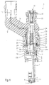
- Fuel injector 1 is described in more detail to better understand the invention, first of all with reference to Fig. 1, the fuel injector 1 with respect to it essential components are briefly explained.
- the fuel injector 1 is in the form of a Fuel injection valve for fuel injection systems of mixture-compressing, spark-ignited Running internal combustion engines.
- the Fuel injection valve 1 is particularly suitable for not directly injecting fuel into one Shown combustion chamber of an internal combustion engine.
- the fuel injector 1 consists of a Nozzle body 2, in which a valve needle 3 is arranged.
- the valve needle 3 stands with a valve closing body 4 in Active connection with one on a valve seat body 5 arranged valve seat surface 6 to a sealing seat interacts.
- the fuel injector 1 is acting it is an inward opening in the exemplary embodiment Fuel injector 1, which has a Spray opening 7 has.
- the nozzle body 2 is through a Seal 8 against the outer pole 9 of a magnetic coil 10 sealed.
- the magnet coil 10 is in a coil housing 11 encapsulated and wound on a bobbin 12, which bears against an inner pole 13 of the magnet coil 10.
- the Inner pole 13 and outer pole 9 are through a gap 26 separated from each other and are based on one Connecting component 29 from.
- the solenoid 10 is a Line 19 from via an electrical plug contact 17th supplyable electric current excited.
- the plug contact 17 is surrounded by a plastic sheath 18, which on Inner pole 13 can be molded.
- the valve needle 3 is in a valve needle guide 14 led, which is disc-shaped. to Stroke adjustment and serves as the lower anchor stop paired stop ring 15.
- On the other side of the Stop ring 15 is an anchor 20. This is standing via a sleeve 21 non-positively with the valve needle 3 in Connection.
- a return spring is supported on the sleeve 21 23, which in the present design of the Fuel injector 1 through a sleeve 24 Bias is brought.
- a Vorhubfeder 22 is arranged, which a has a lower spring constant than the return spring 23 and in connection with a preliminary stroke gap 34 Pre-acceleration of the armature 20 via an armature free path the tightening of the valve needle 3 enables.
- both the sleeve 21 and the Stop ring 15 has a surface structure, which for example in the form of different types of recesses 31 is executed, whereby one facing the armature 20 discharge-side end face 32 of the sleeve 21 and one of the armature 20 facing the inlet end 33 of the stop ring 15 are so malleable in their surface that one by the Operation of the fuel injector 1 caused Wear on the end faces 32 and 33 is controllable so that signs of wear on other components of the Fuel injector 1 can be compensated and therefore do not result in changes in the stroke of the valve needle 3. This can cause malfunctions during continuous operation for example due to a too large static and / or dynamic flow rate due to too large a stroke Valve needle 3 are caused to be avoided.
- the Recesses 31 can alternatively or additionally also the counter surface 38 or the counter surface 39 of the armature 20 be realized.
- FIGS. 2 to 5 The measures according to the invention are shown in FIGS. 2 to 5 detailed and in the following Description explained in more detail.
- valve needle guide 14 in the armature 20 and on Valve seat body 5 run fuel channels 30a to 30c.
- the fuel is supplied via a central fuel supply 16 supplied and filtered by a filter element 25.
- the Fuel injector 1 is against by a seal 28 a fuel rail, not shown sealed.
- the armature 20 takes the sleeve 21, which with the valve needle 3 is welded, and thus the valve needle 3 also in Stroke direction with.
- the one with the valve needle 3 in operative connection standing valve closing body 4 lifts from the valve seat surface 6, whereby the fuel is sprayed off.
- the armature 20 falls sufficient degradation of the magnetic field by the pressure of the Return spring 23 on the sleeve 21 from the inner pole 13, whereby the valve needle 3 against the stroke direction emotional. This sets the valve closing body 4 on the Valve seat 6 and the fuel injector 1 will be closed. The armature 20 is placed on the stop ring 15 on.
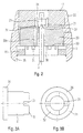
- Fig. 2 shows an excerpt of the sectional view in Fig. 1 marked II from the Fuel injection valve 1 designed according to the invention. Matching components are included in all figures matching reference numerals.
- the lower one Anchor stop through the in a recess 35 of the Fuel injection valve 1 inserted stop ring 15 educated.
- the stop ring 15 has recesses 31, which in the present embodiment in radial Direction are introduced into the stop ring 15 and thereby form a crenellated surface structure.
- the area of the End face 33 of stop ring 15 facing armature 20 is compared to a full-surface stop ring 15th reduced. Signs of wear on the end face 33, which is caused by the armature 20 striking the stop ring 15 induced when the fuel injector 1 closes are stroke-reducing.
- the sleeve 21, which in Fig. 2 for reasons of Clarity is shown without the pre-lift spring 22, radially on its end face 32 facing the armature 20 extending recesses 31, which is also a form a crenellated surface structure. This reduces also the surface of the end face 32, which with the anchor 20 can get in touch.
- FIG. 3A shows a schematic illustration of that in FIG. 2 with 21 designated sleeve of the invention Fuel injector.
- the sleeve 21 Recesses 31 on their armature 20 facing downstream end face 32.
- the sleeve 21 for the preliminary stroke spring 22 is not affected by the recesses 31, since this is clamped between the anchor 20 and a collar 36.
- FIG. 3B shows a schematic top view of that in FIG. 3A sleeve 21 shown.
- the recesses 31 are in equal angular distances of approximately 90 ° into the end face 32 introduced the sleeve 21, creating a crenellated Surface structure is created.
- the surface of the face 32 is reduced by the amount of those in the recesses 31 Reduced area. It can be used to control the Signs of wear also more or less recesses 31 with a larger or smaller angular expansion in larger or smaller distances from each other his.
- FIG. 4A shows a schematic representation of a first Embodiment of the designated in Fig. 2 with 15 Stop ring of the designed according to the invention Fuel injector 1.
- FIG Fig. 4A shown first embodiment of a stop ring 15 according to the invention has a plurality of recesses 31 which reduce the area of the stop ring 15.
- the first exemplary embodiment is twelve recesses 31 provided which, as shown in the schematic supervision 4B on the stop ring 15 shown in Fig. 4A emerges, also at constant angular intervals of approx. 30 ° are arranged.
- FIG. 5A and 5B show a schematic representation as well a schematic plan view of a second Embodiment of the designated in Fig. 2 with 15 Stop ring of the designed according to the invention Fuel injector 1.
- the first embodiment has the stop ring 15 here not several radial recesses 31, but one annular recess 37, which on a radial outer area of the stop ring 15 is formed.
- the Operation of the annular recess 37 is that the radial recesses 31 equate because the area the end face 33 facing the armature 20 likewise is reduced.
- annular recess 37 in the radial direction wider or be made narrower.
- the second embodiment stands out in particular due to its simple manufacture, for example by turning or milling.
- the annular recess 37 is also on the sleeve 21 transferable where it is also in a radially outer Area is attachable.
- the invention is not shown on the Embodiments limited and also for other forms of anchors 20, for example for submersible and flat anchors, as well as any construction of fuel injection valves 1 applicable.
Landscapes
- Engineering & Computer Science (AREA)
- Chemical & Material Sciences (AREA)
- Combustion & Propulsion (AREA)
- Mechanical Engineering (AREA)
- General Engineering & Computer Science (AREA)
- Physics & Mathematics (AREA)
- Electromagnetism (AREA)
- Fuel-Injection Apparatus (AREA)
Abstract
Description
- Fig. 1
- einen schematischen Schnitt durch ein Ausführungsbeispiel eines erfindungsgemäß ausgestalteten Brennstoffeinspritzventils,
- Fig. 2
- einen schematischen Ausschnitt im Bereich II in Fig. 1 aus dem erfindungsgemäß ausgestalteten Brennstoffeinspritzventil in einer leicht variierten Bauweise,
- Fig. 3A
- eine schematische Darstellung der in Fig. 2 mit 21 bezeichneten Hülse des erfindungsgemäß ausgestalteten Brennstoffeinspritzventils,
- Fig. 3B
- eine schematische Aufsicht auf die in Fig. 3A dargestellte Hülse,
- Fig. 4A
- eine schematische Darstellung eines ersten Ausführungsbeispiels des in Fig. 2 mit 15 bezeichneten Anschlagrings des erfindungsgemäß ausgestalteten Brennstoffeinspritzventils,
- Fig. 4B
- eine schematische Aufsicht auf den in Fig. 4A dargestellten Anschlagring,
- Fig. 5A
- eine schematische Darstellung eines zweiten Ausführungsbeispiels des in Fig. 2 mit 15 bezeichneten Anschlagrings des erfindungsgemäß ausgestalteten Brennstoffeinspritzventils, und
- Fig. 5B
- eine schematische Aufsicht auf den in Fig. 5A dargestellten Anschlagring.
Claims (9)
- Brennstoffeinspritzventil (1), insbesondere zum direkten Einspritzen von Brennstoff in den Brennraum einer gemischverdichtenden, fremdgezündeten Brennkraftmaschine, mit einem Anker (20), der mit einer Magnetspule (10) zusammenwirkt, und einer mit dem Anker (20) über eine Hülse (21) in Wirkverbindung stehenden Ventilnadel (3), an der ein Ventilschließkörper (4) vorgesehen ist, der zusammen mit einer Ventilsitzfläche (6) einen Dichtsitz bildet, und einer zwischen der Hülse (21) und dem Anker (20) angeordneten Vorhubfeder (22) sowie einem als Ankeranschlag dienenden Anschlagring (15), der abströmseitig des Ankers (20) angeordnet ist,
dadurch gekennzeichnet, daß an einer dem Anker (20) zugewandten Stirnseite (33) des Anschlagrings (15) und/oder an einer entsprechenden Gegenfläche (38) des Ankers (20) und/oder an einer dem Anker (20) zugewandten Stirnseite (32) der Hülse (21) und/oder einer entsprechenden Gegenfläche (39) des Ankers (20) zumindest eine Ausnehmung (31; 37) ausgebildet ist, welche eine wirksame Anschlagfläche der Stirnseiten (32; 33) verkleinert. - Brennstoffeinspritzventil nach Anspruch 1,
dadurch gekennzeichnet, daß mehrere Ausnehmungen (31) vorgesehen sind. - Brennstoffeinspritzventil nach Anspruch 2,
dadurch gekennzeichnet, daß die Ausnehmungen (31) in radialer Richtung in die Stirnseiten (32; 33) eingebracht sind. - Brennstoffeinspritzventil nach einem der Ansprüche 1 bis 3,
dadurch gekennzeichnet, daß die radialen Ausnehmungen (31) in gleichen Winkelabständen in die Stirnseiten (32; 33) eingebracht sind. - Brennstoffeinspritzventil nach einem der Ansprüche 1 bis 4,
dadurch gekennzeichnet, daß die radialen Ausnehmungen (31) gleiche Winkelbereiche in Anspruch nehmen. - Brennstoffeinspritzventil nach Anspruch 1,
dadurch gekennzeichnet, daß die Ausnehmungen (37) ringförmig ausgebildet sind. - Brennstoffeinspritzventil nach Anspruch 6,
dadurch gekennzeichnet, daß die ringförmigen Ausnehmungen (37) in einem radial äußeren Bereich der Stirnflächen (32; 33) ausgebildet sind. - Brennstoffeinspritzventil nach Anspruch 6 oder 7,
dadurch gekennzeichnet, daß die ringförmigen Ausnehmungen (37) durch Drehen hergestellt sind. - Brennstoffeinspritzventil nach einem der Ansprüche 1 bis 8,
dadurch gekennzeichnet, daß die Ausnehmungen (31; 37) durch Fräsen hergestellt sind.
Applications Claiming Priority (2)
| Application Number | Priority Date | Filing Date | Title |
|---|---|---|---|
| DE10148592 | 2001-10-02 | ||
| DE2001148592 DE10148592A1 (de) | 2001-10-02 | 2001-10-02 | Brennstoffeinspritzventil |
Publications (3)
| Publication Number | Publication Date |
|---|---|
| EP1300583A2 true EP1300583A2 (de) | 2003-04-09 |
| EP1300583A3 EP1300583A3 (de) | 2003-04-23 |
| EP1300583B1 EP1300583B1 (de) | 2009-08-05 |
Family
ID=7701118
Family Applications (1)
| Application Number | Title | Priority Date | Filing Date |
|---|---|---|---|
| EP20020021426 Expired - Lifetime EP1300583B1 (de) | 2001-10-02 | 2002-09-25 | Brennstoffeinspritzventil |
Country Status (3)
| Country | Link |
|---|---|
| EP (1) | EP1300583B1 (de) |
| JP (1) | JP4217453B2 (de) |
| DE (2) | DE10148592A1 (de) |
Cited By (1)
| Publication number | Priority date | Publication date | Assignee | Title |
|---|---|---|---|---|
| WO2017029031A1 (de) * | 2015-08-14 | 2017-02-23 | Robert Bosch Gmbh | Ventil zum zumessen eines fluids |
Citations (1)
| Publication number | Priority date | Publication date | Assignee | Title |
|---|---|---|---|---|
| DE19849210A1 (de) | 1998-10-26 | 2000-04-27 | Bosch Gmbh Robert | Brennstoffeinspritzventil |
Family Cites Families (7)
| Publication number | Priority date | Publication date | Assignee | Title |
|---|---|---|---|---|
| DE3501973A1 (de) * | 1984-01-23 | 1985-07-25 | Nippondenso Co., Ltd., Kariya, Aichi | Brennstoff-einspritzduese |
| JPS63109277A (ja) * | 1986-10-28 | 1988-05-13 | Aisan Ind Co Ltd | 電磁式燃料噴射弁 |
| DE3834447A1 (de) * | 1988-10-10 | 1990-04-12 | Mesenich Gerhard | Elektromagnetisches einspritzventil und verfahren zu dessen herstellung |
| DE4421935A1 (de) * | 1993-12-09 | 1995-06-14 | Bosch Gmbh Robert | Elektromagnetisch betätigbares Ventil |
| DE19626576A1 (de) * | 1996-07-02 | 1998-01-08 | Bosch Gmbh Robert | Brennstoffeinspritzventil |
| DE19816315A1 (de) * | 1998-04-11 | 1999-10-14 | Bosch Gmbh Robert | Brennstoffeinspritzventil |
| DE19960605A1 (de) * | 1999-12-16 | 2001-07-19 | Bosch Gmbh Robert | Brennstoffeinspritzventil |
-
2001
- 2001-10-02 DE DE2001148592 patent/DE10148592A1/de not_active Withdrawn
-
2002
- 2002-09-25 EP EP20020021426 patent/EP1300583B1/de not_active Expired - Lifetime
- 2002-09-25 DE DE50213737T patent/DE50213737D1/de not_active Expired - Lifetime
- 2002-10-02 JP JP2002290018A patent/JP4217453B2/ja not_active Expired - Fee Related
Patent Citations (1)
| Publication number | Priority date | Publication date | Assignee | Title |
|---|---|---|---|---|
| DE19849210A1 (de) | 1998-10-26 | 2000-04-27 | Bosch Gmbh Robert | Brennstoffeinspritzventil |
Cited By (2)
| Publication number | Priority date | Publication date | Assignee | Title |
|---|---|---|---|---|
| WO2017029031A1 (de) * | 2015-08-14 | 2017-02-23 | Robert Bosch Gmbh | Ventil zum zumessen eines fluids |
| US11053900B2 (en) | 2015-08-14 | 2021-07-06 | Robert Bosch Gmbh | Valve for metering a fluid |
Also Published As
| Publication number | Publication date |
|---|---|
| EP1300583A3 (de) | 2003-04-23 |
| JP4217453B2 (ja) | 2009-02-04 |
| EP1300583B1 (de) | 2009-08-05 |
| DE10148592A1 (de) | 2003-04-10 |
| JP2003120462A (ja) | 2003-04-23 |
| DE50213737D1 (de) | 2009-09-17 |
Similar Documents
| Publication | Publication Date | Title |
|---|---|---|
| EP1309793B1 (de) | Brennstoffeinspritzventil | |
| EP1309789B1 (de) | Brennstoffeinspritzventil | |
| EP1315900B1 (de) | Brennstoffeinspritzventil | |
| WO2002068811A1 (de) | Brennstoffeinspritzventil | |
| EP1434941A1 (de) | Brennstoffeinspritzventil | |
| EP1576278A1 (de) | Brennstoffeinspritzventil | |
| DE10360330A1 (de) | Brennstoffeinspritzventil | |
| EP1155231A1 (de) | Brennstoffeinspritzventil | |
| EP1481157B1 (de) | Brennstoffeinspritzventil | |
| WO2002025100A1 (de) | Brennstoffeinspritzventil | |
| EP1312796B1 (de) | Brennstoffeinspritzventil | |
| EP1570170A1 (de) | Brennstoffeinspritzventil | |
| DE10345967B4 (de) | Brennstoffeinspritzventil | |
| EP1570174A1 (de) | Brennstoffeinspritzventil | |
| DE10361761A1 (de) | Brennstoffeinspritzventil | |
| EP1402171B1 (de) | Brennstoffeinspritzventil und verfahren zu dessen einstellung | |
| DE10063261B4 (de) | Brennstoffeinspritzventil | |
| DE102005048545B4 (de) | Brennstoffeinspritzventil | |
| EP1300583B1 (de) | Brennstoffeinspritzventil | |
| DE10326343A1 (de) | Brennstoffeinspritzventil | |
| DE10051900A1 (de) | Brennstoffeinspritzventil | |
| DE10103050A1 (de) | Brennstoffeinspritzventil | |
| DE10331805A1 (de) | Brennstoffeinspritzventil | |
| DE102005019329A1 (de) | Elektromagnetisch betätigbares Ventil | |
| DE10153627A1 (de) | Brennstoffeinspritzventil |
Legal Events
| Date | Code | Title | Description |
|---|---|---|---|
| PUAI | Public reference made under article 153(3) epc to a published international application that has entered the european phase |
Free format text: ORIGINAL CODE: 0009012 |
|
| PUAL | Search report despatched |
Free format text: ORIGINAL CODE: 0009013 |
|
| AK | Designated contracting states |
Kind code of ref document: A2 Designated state(s): AT BE BG CH CY CZ DE DK EE ES FI FR GB GR IE IT LI LU MC NL PT SE SK TR |
|
| AX | Request for extension of the european patent |
Extension state: AL LT LV MK RO SI |
|
| AK | Designated contracting states |
Designated state(s): AT BE BG CH CY CZ DE DK EE ES FI FR GB GR IE IT LI LU MC NL PT SE SK TR |
|
| AX | Request for extension of the european patent |
Extension state: AL LT LV MK RO SI |
|
| 17P | Request for examination filed |
Effective date: 20031023 |
|
| AKX | Designation fees paid |
Designated state(s): DE FR IT |
|
| 17Q | First examination report despatched |
Effective date: 20040217 |
|
| 17Q | First examination report despatched |
Effective date: 20040217 |
|
| GRAP | Despatch of communication of intention to grant a patent |
Free format text: ORIGINAL CODE: EPIDOSNIGR1 |
|
| GRAS | Grant fee paid |
Free format text: ORIGINAL CODE: EPIDOSNIGR3 |
|
| GRAA | (expected) grant |
Free format text: ORIGINAL CODE: 0009210 |
|
| AK | Designated contracting states |
Kind code of ref document: B1 Designated state(s): DE FR IT |
|
| REF | Corresponds to: |
Ref document number: 50213737 Country of ref document: DE Date of ref document: 20090917 Kind code of ref document: P |
|
| PLBE | No opposition filed within time limit |
Free format text: ORIGINAL CODE: 0009261 |
|
| STAA | Information on the status of an ep patent application or granted ep patent |
Free format text: STATUS: NO OPPOSITION FILED WITHIN TIME LIMIT |
|
| 26N | No opposition filed |
Effective date: 20100507 |
|
| REG | Reference to a national code |
Ref country code: FR Ref legal event code: PLFP Year of fee payment: 14 |
|
| PGFP | Annual fee paid to national office [announced via postgrant information from national office to epo] |
Ref country code: FR Payment date: 20150923 Year of fee payment: 14 |
|
| PGFP | Annual fee paid to national office [announced via postgrant information from national office to epo] |
Ref country code: DE Payment date: 20151125 Year of fee payment: 14 Ref country code: IT Payment date: 20150925 Year of fee payment: 14 |
|
| REG | Reference to a national code |
Ref country code: DE Ref legal event code: R119 Ref document number: 50213737 Country of ref document: DE |
|
| REG | Reference to a national code |
Ref country code: FR Ref legal event code: ST Effective date: 20170531 |
|
| PG25 | Lapsed in a contracting state [announced via postgrant information from national office to epo] |
Ref country code: DE Free format text: LAPSE BECAUSE OF NON-PAYMENT OF DUE FEES Effective date: 20170401 Ref country code: FR Free format text: LAPSE BECAUSE OF NON-PAYMENT OF DUE FEES Effective date: 20160930 |
|
| PG25 | Lapsed in a contracting state [announced via postgrant information from national office to epo] |
Ref country code: IT Free format text: LAPSE BECAUSE OF NON-PAYMENT OF DUE FEES Effective date: 20160925 |