EP1300285B1 - Arrangement for locking of different types of containers on a chassis - Google Patents
Arrangement for locking of different types of containers on a chassis Download PDFInfo
- Publication number
- EP1300285B1 EP1300285B1 EP02021520A EP02021520A EP1300285B1 EP 1300285 B1 EP1300285 B1 EP 1300285B1 EP 02021520 A EP02021520 A EP 02021520A EP 02021520 A EP02021520 A EP 02021520A EP 1300285 B1 EP1300285 B1 EP 1300285B1
- Authority
- EP
- European Patent Office
- Prior art keywords
- locking
- locking device
- arrangement according
- chassis
- pin
- Prior art date
- Legal status (The legal status is an assumption and is not a legal conclusion. Google has not performed a legal analysis and makes no representation as to the accuracy of the status listed.)
- Expired - Lifetime
Links
Images


Classifications
-
- B—PERFORMING OPERATIONS; TRANSPORTING
- B60—VEHICLES IN GENERAL
- B60P—VEHICLES ADAPTED FOR LOAD TRANSPORTATION OR TO TRANSPORT, TO CARRY, OR TO COMPRISE SPECIAL LOADS OR OBJECTS
- B60P7/00—Securing or covering of load on vehicles
- B60P7/06—Securing of load
- B60P7/13—Securing freight containers or forwarding containers on vehicles
- B60P7/132—Securing freight containers or forwarding containers on vehicles twist-locks for containers or frames
-
- B—PERFORMING OPERATIONS; TRANSPORTING
- B60—VEHICLES IN GENERAL
- B60P—VEHICLES ADAPTED FOR LOAD TRANSPORTATION OR TO TRANSPORT, TO CARRY, OR TO COMPRISE SPECIAL LOADS OR OBJECTS
- B60P1/00—Vehicles predominantly for transporting loads and modified to facilitate loading, consolidating the load, or unloading
- B60P1/64—Vehicles predominantly for transporting loads and modified to facilitate loading, consolidating the load, or unloading the load supporting or containing element being readily removable
- B60P1/6418—Vehicles predominantly for transporting loads and modified to facilitate loading, consolidating the load, or unloading the load supporting or containing element being readily removable the load-transporting element being a container or similar
- B60P1/6481—Specially adapted for carrying different numbers of container or containers of different sizes
Landscapes
- Engineering & Computer Science (AREA)
- Transportation (AREA)
- Mechanical Engineering (AREA)
- Body Structure For Vehicles (AREA)
- Auxiliary Devices For And Details Of Packaging Control (AREA)
- Fittings On The Vehicle Exterior For Carrying Loads, And Devices For Holding Or Mounting Articles (AREA)
- Supplying Of Containers To The Packaging Station (AREA)
- Container Filling Or Packaging Operations (AREA)
- Automatic Assembly (AREA)
- Automobile Manufacture Line, Endless Track Vehicle, Trailer (AREA)
- Filling Of Jars Or Cans And Processes For Cleaning And Sealing Jars (AREA)
- Wrapping Of Specific Fragile Articles (AREA)
- Lock And Its Accessories (AREA)
Abstract
Description
Die Erfindung betrifft eine Anordnung zur Halterung unterschiedlicher Container-Typen auf einem Fahrgestell gemäß den Merkmalen der Oberbegriffe der unabhängigen Ansprüche 1 oder 26, sowie ein entsprechendes Fahrgestell gemäß dem unabhängigen Anspruch 30.The invention relates to an arrangement for holding different types of containers on a chassis according to the features of the preambles of independent claims 1 or 26, and a corresponding chassis according to independent claim 30.
Als Wechselbehälter auf Fahrgestellen sind Container verschiedener Größe gebräuchlich, welche im unteren Bereich von Stirnseiten und Längsseiten Beschläge aufweisen, in welche fahrzeugseitige Verriegelungen eingreifen können. Neben ISO-Containern mit ebener Auflagefläche sind insbesondere sogenannte High Cube (HC)- oder Gooseneck-Container von Bedeutung, welche zur Frontseite hin in einem Bereich um die Mittellängsebene des Containers einen sogenannten Gooseneck-Tunnel aufweisen, welcher eine Stufe der Längsträger des Fahrgestells seitlich umgreift.As swap bodies on chassis are containers of different sizes common, which in the lower part of front and long sides fittings have, in which vehicle-side latches can intervene. In addition to ISO containers with a flat bearing surface are in particular so-called High Cube (HC) - or Gooseneck container of importance, which towards the front in an area around the central longitudinal plane of the container have a so-called gooseneck tunnel, which is a stage of Side member of the chassis engages laterally.
Gebräuchlich sind insbesondere Container der Länge 20' und 40' mit und ohne Gooseneck-Tunnel sowie Container der Länge 45' mit Gooseneck-Tunnel, wobei für letztere zur Einhaltung von Vorschriften hinsichtlich Gesamtlänge und frontseitigem Schwenkradius bekannt ist, die Ecksäulen anzuschrägen, um einen begrenzten Schwenkradius um den Königszapfen nicht zu überschreiten.In particular, containers of length 20 'and 40' with and without are common Gooseneck tunnel and container of length 45 'with gooseneck tunnel, where for the latter to comply with rules regarding total length and Front Schwenkradius is known to bevel the corner pillars to a Limited swing radius to not exceed the kingpin.
Zur frontseitigen Halterung der unterschiedlichen Containertypen sind unterschiedliche Verriegelungsvorrichtungen an einem frontseitigen Querträger, welcher vorzugsweise in Längsrichtung in verschiedene Positionen verstellbar ist, bekannt, insbesondere für ISO-Container Drehzapfen-Verriegelungen mit vertikalen, über die Aufliegeebene des Fahrgestells hinausragenden und von unten in Öffnungen von Container-Beschlägen hineinragenden Drehzapfen. Bei HC-Containern der Länge 45' sind in den abgeschrägten Eckbeschlägen die Öffnungen zur Aufnahme von horizontalen Steckbolzen gegenüber der Position bei gleich breiten Containern ohne Abschrägung zur Mittellängsebene des Containers hin um ein geringes Maß versetzt. Container mit derart abgeschrägten Eckbeschlägen sind beispielsweise beschrieben in WO98/19883 A1.For front-side mounting of the different container types are different Locking devices on a front cross member, which preferably in the longitudinal direction in different positions is adjustable, known, especially for ISO container pivot locks with vertical, protruding beyond the landing plane of the chassis and from below in openings of container fittings protruding pivot. For HC containers of length 45 'are the openings in the beveled corner fittings for receiving horizontal pins against the position for equally wide containers without bevel to the central longitudinal plane of the Containers offset by a small amount. Container with such bevelled Corner fittings are described for example in WO98 / 19883 A1.
Um einerseits mit einer Anordnung verschiedene Container-Typen halten zu können und andererseits die Vorschriften auch bei 45'-Containern einhalten zu können sind verschiedene Kombi-Anordnungen bekannt. Beispielsweise beschreibt eine Pressemitteilung zur IAA 2000 ein Verriegelungssystem unter der Bezeichnung Winglock, welches durch abgeschrägte und seitlich verfahrbare Verriegelungsarme mit Steckbolzen die Halterung von HC-Containern mit abgeschrägten und mit rechteckigen Beschlägen ermöglicht. Die Anordnung ermöglicht aber nicht die Halterung von ISO-Containern mittels vertikaler Drehzapfen. Dasselbe Verriegelungssystem ist auch Gegenstand der EP 0 965 485 A2.On the one hand with an arrangement different types of containers to hold On the other hand, the regulations also apply to 45 'containers Various combination arrangements are known. For example, describes a press release on the IAA 2000 a locking system under the Name Winglock, which by bevelled and laterally movable Locking arms with locking pins the holder of HC containers with bevelled and with rectangular fittings allows. The arrangement allows but not the holder of ISO containers by means of vertical pivots. The same locking system is also the subject of EP 0 965 485 A2.
Aus der gattungsbildenden DE 200 12 977 U1 ist eine Vorrichtung bekannt, welche an einem Querträger nach oben zur Containermitte hin wegschwenkbare Schwenkarme enthält. Die Schwenkarme weisen an den äußeren Enden zum einen eine vertikale Drehzapfenverriegelung und zum anderen eine horizontale Steckbolzenverriegelung für HC-Container mit rechteckigen Beschlägen auf und können in ausgeklappter Stellung zur Halterung von passenden Containern dienen. Zusätzlich sind nahe bei der Mittellängsebene des Fahrgestells an dem Querträger weitere Steckbolzenverriegelungen vorgesehen, welche innerhalb eines zulässigen Durchdrehradius um den Königszapfen liegen und in entsprechend nahe bei der Mittellängsebene eines 45'-HC-Containers befindliche Beschläge eingreifen können welche hierfür gesondert vorgesehen werden müssen. Die in Parkstellung hochgeklappten Schwenkarme befinden sich gleichfalls vollständig innerhalb des genannten Durchdrehradius.From the generic DE 200 12 977 U1 a device is known which can be pivoted upwards to the middle of the container on a cross member Swing arms contains. The pivot arms point at the outer ends on the one hand a vertical pivot lock and on the other hand a horizontal one Locking pin lock for HC containers with rectangular fittings on and in unfolded position for holding suitable containers serve. In addition, they are close to the central longitudinal plane of the chassis provided on the cross member further locking pin locks, which lie within a permissible radius of rotation around the kingpin and located in close proximity to the central longitudinal plane of a 45 'HC container Forged can intervene which must be provided separately for this purpose. In the Parking position folded swivel arms are also completely within the specified turning radius.
Verriegelungsanordnungen mit einer Drehzapfenverriegelung und einer Steckbolzenverriegelung sind auch aus der DE 196 06 263 A1, wo ein Drehzapfen-Verriegelungsgehäuse um eine durch den Steckbolzen führende vertikale Schwenkachse verschwenkt und auf dem Querträger abgesetzt werden kann, und aus der DE 100 47 093 A1, wo die Schwenkachse in Fahrtrichtung vor dem Steckbolzen liegt, bekannt. Diese Verriegelungsanordnungen, bei welchen das Drehzapfen-Verriegelungsgehäuse in seiner Halteposition in Verriegelungsrichtung des Steckbolzens liegt, sind aber nicht auch zur Halterung von 45'-HC-Containern geeignet.Locking arrangements with a pivot lock and a locking pin lock are also known from DE 196 06 263 A1, where a pivot locking housing around a leading through the socket pin vertical Swivel axis pivoted and can be discontinued on the cross member, and from DE 100 47 093 A1, where the pivot axis in the direction of travel before the Locking pin lies, known. These locking arrangements in which the Trunnion lock housing in its holding position in the locking direction of the pin is, but are not synonymous for holding 45'-HC containers suitable.
Der Erfindung liegt die Aufgabe zugrunde, eine vorteilhafte Anordnung zur Halterung unterschiedlicher Container anzugeben.The invention is based on the object, an advantageous arrangement for Specify bracket different containers.
Erfindungsgemäße Anordnungen sind in den unabhängigen Patentansprüchen 1 und 26 beschrieben. Die abhängigen Ansprüche enthalten vorteilhafte Ausgestaltungen und Weiterbildungen der Erfindung. Der unabhängige Patentanspruch 30 betrifft ein Fahrgestell mit einer derartigen Anordnung.Arrangements according to the invention are in the independent patent claims 1 and 26 described. The dependent claims contain advantageous embodiments and further developments of the invention. The independent claim 30 relates to a chassis with such an arrangement.
Die vom Steckbolzen der zweiten Verriegelungseinrichtung getrennte Anordnung der ersten Verriegelungseinrichtung mit dem Verriegelungszapfen für Container eines ersten Container-Typs an einem Schwenkarm ermöglicht vorteilhafterweise die einfache Verlagerung der ersten Verriegelungseinrichtung zwischen einer Halteposition, in welcher ein Container mittels des vertikal von unten in den Eckbeschlag eingreifenden Drehzapfens verriegelbar ist, und einer Parkposition, in welcher bei Verriegelung eines 45'-HC-Containers mittels des Steckbolzens der zweiten Verriegelungseinrichtung die erste Verriegelungseinrichtung vollständig innerhalb des vorgeschriebenen Drehkreisradius um den Königszapfen liegt.The separate from the locking pin of the second locking device arrangement the first locking device with the locking pin for Container of a first container type on a pivoting arm advantageously allows the simple displacement of the first locking device between a holding position in which a container by means of the vertical of lockable in the corner fitting engaging pivot, and a Park position, in which when locking a 45'-HC container by means of Plug pin of the second locking device, the first locking device completely within the prescribed circle radius around the Kingpin lies.
Bei den Verriegelungseinrichtungen sei hierbei und im folgenden als selbstverständlich vorausgesetzt, dass diese jeweils paarweise an entgegengesetzten Enden des Querträgers auftreten.In the locking devices here and in the following as a matter of course provided that they are pairwise opposite Ends of the cross member occur.
Die zweite Verriegelungseinrichtung weist vorzugsweise einen Bolzenträger auf, auf welchem der Steckbolzen angeordnet ist und welcher aus einer Halteposition, in welcher ein Container zweiten Typs verriegelbar ist, in seiner Position relativ zu dem Querträger verlagerbar ist. Gemäß einer bevorzugten Ausführung ist der Bolzenträger gleichfalls als relativ zum Querträger schwenkbarer, vom Schwenkarm der ersten Verriegelungsanordnung verschiedener Schwenkarm ausgebildet.The second locking device preferably has a bolt carrier on which the plug pin is arranged and which from a holding position, in which a container of the second type is lockable, in its position is displaceable relative to the cross member. According to a preferred embodiment the bolt carrier is also pivotable relative to the cross member, from the pivot arm of the first locking arrangement different Swing arm formed.
Die getrennte Anordnung von Steckbolzen und Verriegelungszapfen als Verriegelungselementen für unterschiedliche Container-Typen über verschiedene schwenkbare Trägerarme an einem gemeinsamen, in Längsrichtung des Fahrgestells variabel positionierbaren Querträger ermöglicht zum einen die unabhängige mechanische Positionierung eines der Verriegelungselemente in dessen jeweiliger Halteposition am Eckbeschlag des zugehörigen ContainerTyps und zum anderen das Verschwenken des jeweils anderen Verriegelungselements aus dessen Halteposition, soweit diese für den Einsatz des einen Verriegelungselements störend ist.The separate arrangement of locking pins and locking pins as locking elements for different container types over different pivotable support arms on a common, in the longitudinal direction of the chassis variably positionable cross member allows for an independent mechanical positioning of one of the locking elements in the respective holding position at the corner fitting of the associated container type and on the other hand the pivoting of the respective other locking element from its holding position, as far as this for the use of a locking element is disturbing.
Dies gilt insbesondere für die Halteposition der zweiten Verriegelungseinrichtung für Container-Typen, bei welchen der Eckbeschlag sehr nahe an dem zulässigen Durchdrehkreis liegt und, um diesen nicht zu überragen, auch abgeschrägt sein kann, wobei die Festlegung des Containers durch einen horizontal in den Eckbeschlag eingreifenden Steckbolzen erfolgt. Die in der Halteposition innerhalb des zulässigen Durchdrehkreises liegende zweite Verriegelungseinrichtung schwenkt beim Lösen typischerweise über den Durchdrehkreis hinaus. Bei Verriegelung eines zweiten Container-Typs durch die zweite Verriegelungseinrichtung ist die erste Verriegelungseinrichtung durch Verschwenken des Schwenkarms in Richtung zur Mittellängsebene des Fahrgestells verlagert und befindet sich gleichfalls innerhalb des zulässigen Durchdrehkreises, wobei aber beide Verriegelungseinrichtungen mit Eckbeschlägen der jeweiligen Container korrespondieren und keine zusätzlichen Container-Beschläge erforderlich.This applies in particular to the holding position of the second locking device for container types where the corner fitting is very close to the permissible one Rotary circle is located and, not to exceed this, also bevelled can be, with the determination of the container by a horizontal in the corner fitting engaging socket pin takes place. The in the holding position within the allowable spin cycle lying second locking device typically pivots beyond the spin circle when released. When locking a second container type by the second locking device is the first locking device by pivoting the Swivel arm in the direction of the central longitudinal plane of the chassis shifted and is also within the allowable spin circle, but both locking devices with corner fittings of the respective container correspond and no additional container fittings required.
Die separat verschwenkbare Anordnung beider Verriegelungseinrichtungen an einem gemeinsamen Querträger führt dabei zu einer besonders vorteilhaften und kompakten Anordnung, ohne dass wie bei der aus der DE 200 12 977 U1 zusätzliche Beschläge nahe der Mittellängsachse erforderlich sind. Vorzugsweise überdeckt der Schwenkarm in der Halteposition der ersten Verriegelungseinrichtung wenigstens teilweise die Halteposition des Bolzenträgers, jeweils relativ zu dem gemeinsamen Querträger betrachtet.The separately pivotable arrangement of both locking devices a common cross member leads to a particularly advantageous and compact arrangement, without that as in DE 200 12 977 U1 additional fittings near the central longitudinal axis are required. Preferably covers the pivot arm in the holding position of the first locking device at least partially the holding position of the bolt carrier, respectively considered relative to the common cross member.
Die zweite Verriegelungseinrichtung ist insbesondere für überlange HC-Container-Typen mit abgeschrägten Eckbeschlägen vorgesehen, bei welchen die Position des Steckbolzens gegenüber nicht abgeschrägten Eckbeschlägen um ca. 85 mm zur Fahrgestell-Mittellängsebene hin versetzt ist. Zur Verriegelung von HC-Container-Typen mit nicht abgeschrägten Eckbeschlägen mittels horizontaler Steckbolzen sind daher andere Bolzen-Positionen vorzusehen. Hierfür kann gemäß einer bevorzugten Ausführung eine dritte Verriegelungseinrichtung vorhanden sein, welche insbesondere baulich vereinigt mit der ersten Verriegelungseinrichtung an dem Schwenkarm angeordnet sein kann. In anderer Ausführung kann auch durch Querverschiebbarkeit des Bolzenträgers derselbe Steckbolzen für die zweite und die dritte Verriegelungseinrichtung benutzt sein.The second locking device is particularly for overlong HC container types provided with bevelled corner fittings, in which the position of the pin against non-bevelled corner fittings is offset by about 85 mm to the chassis center longitudinal plane. For locking HC container types with non-bevelled corner fittings by means of Horizontal locking pins are therefore to provide other bolt positions. For this purpose, according to a preferred embodiment, a third locking device be present, which in particular structurally associated with the first Locking device can be arranged on the pivot arm. In others Execution can also by Querverschiebbarkeit the bolt carrier the same Locking pin used for the second and third locking device be.
Als Halteposition der verschiedenen Verriegelungseinrichtungen seien dabei die Positionen verstanden, in welchen die jeweiligen Verriegelungselemente, insbesondere Steckbolzen oder vertikale Verriegelungszapfen in Eingriff mit Containerbeschlägen stehen. Da nur jeweils eine der Verriegelungen benutzt wird befinden sich die anderen Verriegelungen, soweit sie der aktuell benutzten Verriegelung im Wege stünden oder anderweitig stören könnten, dann vorzugsweise in als Parkpositionen bezeichneten definierten Positionen, welche von den Haltepositionen verschieden sind. Die Verriegelungseinrichtungen sind vorteilhafterweise in ihren Haltepositionen und vorzugsweise auch in ihren Parkpositionen durch Sicherungselemente festlegbar. Verlagerungen einer Verriegelungseinrichtung zwischen der Halteposition und der Parkposition können je nach Ausführungsform Bewegungskomponenten mit Ausweichfunktion in Zwischenpositionen umfassen.As a holding position of the various locking devices are doing understood the positions in which the respective locking elements, in particular socket pin or vertical locking pin engaged with Container fittings stand. Since only one of the locks used the other interlocks are located, as far as they are currently used Locking in the way or otherwise disturbing, then preferably in defined as parking positions defined positions, which are different from the holding positions. The locking devices are advantageously in their holding positions and preferably also in their Parking positions can be determined by securing elements. Displacements of a locking device between the stop position and the parking position can Depending on the embodiment, movement components with evasive function in Include intermediate positions.
Die dritte Verriegelungseinrichtung kann in verschiedenen vorteilhaften Ausführungen mit der erfindungsgemäßen Kombination der ersten und der zweiten Verriegelungseinrichtung realisiert sein. Eine erste Ausführung kann die dritte Verriegelungseinrichtung auf einen eigenen, relativ zum Bolzenträger der zweiten Verriegelungseinrichtung und/oder zum Schwenkarm der ersten Verriegelungseinrichtung vorsehen. Eine andere vorteilhafte Ausführungsform kann vorsehen, dass die dritte Verriegelungseinrichtung denselben Steckbolzen benutzt wie die zweite Verriegelungseinrichtung, wofür eine Trägeranordnung für diesen Steckbolzen in Richtung des Querträgers, d.h. quer zur Fahrgestell-Längsachse verstellbar und mit dem Steckbolzen in verschiedene Abstände zur Mittellängsebene gebracht werden kann. Dies kann beispielsweise ähnlich der von der genannten Winglock-Verriegelung bekannten Verschiebung eines einen schwenkbaren Bolzenarm tragenden Teleskop-Trägerrohres erfolgen. Eine andere Variante kann vorsehen, dass bei einem den Steckbolzen tragenden, um eine vertikale Schwenkachse schwenkbaren Träger die Schwenkachse in einem Langloch geführt und dadurch der seitliche Abstand des Trägers und damit des Schwenkbolzens variiert werden kann.The third locking device may be in various advantageous embodiments with the inventive combination of the first and the second Be realized locking device. A first execution may be the third Locking device on its own, relative to the bolt carrier of second locking device and / or the pivot arm of the first locking device provide. Another advantageous embodiment may provide that the third locking device the same locking pin used as the second locking device, what a carrier assembly for this pin in the direction of the cross member, i. transverse to the chassis longitudinal axis adjustable and with the locking pin in different distances to Middle longitudinal plane can be brought. This can be similar to the example known from the aforementioned Winglock lock displacement of a pivotable bolt arm carrying telescopic support tube done. A another variant may provide that when the plug pin bearing, pivotable about a vertical pivot axis support the pivot axis in guided a slot and thereby the lateral distance of the wearer and so that the pivot pin can be varied.
in wieder anderer, bevorzugter Ausführung kann die dritte Verriegelungseinrichtung am Ende des die erste Verriegelungseinrichtung tragenden Schwenkarms gemeinsam mit dieser angeordnet sein. Ein besonders vorteilhaftes Beispiel hierfür ist in den Abbildungen dargestellt und zusammen mit diesen noch eingehend erläutert.In yet another, preferred embodiment, the third locking device at the end of the first locking device bearing pivot arm be arranged together with this. A particularly advantageous example this is shown in the pictures and together with these explained in detail.
Durch die Verschwenkung in die Parkposition kann die erste Verriegelungseinrichtung mit dem Hebelarm in einen Bereich innerhalb des zulässigen Durchdrehkreises um den Königszapfen gebracht werden. Die Verschwenkung des Schwenkarms kann um eine im wesentlichen horizontale Achse erfolgen, welche vorzugsweise näher bei der Mittellängsebene liegt als ein Mechanismus zur horizontalen Verschiebung des Steckbolzens der zweiten Verriegelungseinrichtung. Der Schwenkarm kann dann vorteilhafterweise in Form eines zur zweiten Verriegelungseinrichtung nach unten hin offenen U-Profils ausgeführt sein, welches in der Halteposition der dritten Verriegelungseinrichtung die - zweite Verriegelungseinrichtung in deren Parkposition seitlich umgibt.By pivoting in the parking position, the first locking device with the lever arm into an area within the permissible spin circle to be brought to the kingpin. The pivoting of the Schwenkarms can take place about a substantially horizontal axis, which preferably closer to the central longitudinal plane than a mechanism for horizontal displacement of the plug pin of the second locking device. The swivel arm can then advantageously in the form of a second locking device running down towards open U-profile which, in the holding position of the third locking device, the - second locking device in the parking position laterally surrounds.
Vorzugsweise ist der Schwenkarm um eine vertikale Achse schwenkbar, die insbesondere in konstruktiv günstiger Weise mit einer Schwenkachse eines fest mit dem Steckbolzen der zweiten Verriegelungseinrichtung verbundenen Bolzenträgers zusammenfallen kann. Der Schwenkarm ist dabei aus der Halteposition um nahezu 180°, vorzugsweise zwischen 150° und 180° in die Parkposition verschwenkbar. Die Schwenkachse des Schwenkarms der ersten Verriegelungseinrichtung liegt vorteilhafterweise in Richtung quer zur Längsrichtung des Fahrgestells zwischen der Halteposition der Steckbolzen der zweiten Verriegelungseinrichtung und der Mittellängsebene des Fahrgestells. Die erste Verriegelungseinrichtung liegt in ihrer Parkposition vorteilhafterweise weniger als 50 % einer halben Containerbreite von der Mittellängsebene beabstandet.Preferably, the pivot arm is pivotable about a vertical axis, the especially in a structurally favorable manner with a pivot axis of a fixed bolt carrier connected to the locking pin of the second locking device can coincide. The swivel arm is out of the holding position by almost 180 °, preferably between 150 ° and 180 ° in the parking position pivotable. The pivot axis of the pivot arm of the first locking device is advantageously in the direction transverse to the longitudinal direction the chassis between the holding position of the locking pin of the second locking device and the central longitudinal plane of the chassis. The first locking device is in its parking position advantageously less than 50% of half a container width from the central longitudinal plane spaced.
Vorteilhafterweise ist der Querträger als in Fahrtrichtung zumindest teilweise offenes Profil ausgeführt und nimmt den Schwenkarm und eventuell auch die mit diesem verbundene erste Verriegelungseinrichtung durch die Profilöffnung zumindest teilweise auf. In der ersten Verriegelungseinrichtung ist hierfür vorteilhafterweise vorgesehen, den Verriegelungs-Zapfen so verlagern zu können, dass er nicht über die vertikalen Abmessungen des Verriegelungsgehäuses hinausragt.Advantageously, the cross member is at least partially in the direction of travel executed open profile and takes the swivel arm and possibly the connected to this first locking device through the profile opening at least partially. In the first locking device this is advantageously provided to be able to shift the locking pin so that he does not have the vertical dimensions of the lock housing protrudes.
Bei um eine gemeinsame vertikale Achse verschwenkbarem Schwenkarm der ersten und Bolzenträger der zweiten Verriegelungseinrichtung nehmen vorteilhafterweise Schwenkarm und Bolzenträger in bezüglich der Schwenkachse achsialer, d.h. vertikaler Richtung unterschiedliche Abschnitte ein und können so einfach gegeneinander um die gemeinsame Schwenkachse verschwenkt werden. Hierbei kann es unter Umständen günstig sein, wenn Bolzenträger und Schwenkarm auch relativ zueinander radial verschiebbar sind, um einerseits die geringe Differenz des seitlichen Abstands von der Mittellängsebene des Fahrgestells zwischen den Verriegelungselementen der zweiten und der dritten Verriegelungselementen konstruktiv vorteilhaft realisieren zu können und andererseits den Bolzenträgern an der ersten Verriegelungseinrichtung an dem Schwenkarm vorbei zu führen.When pivotable about a common vertical axis pivot arm of first and bolt carrier of the second locking device advantageously take Swivel arm and bolt carrier with respect to the pivot axis achsialer, i. vertical direction different sections and can so easily pivoted against each other about the common pivot axis become. This may be favorable under certain circumstances, if bolt carrier and Swivel arm also relative to each other are radially displaceable, on the one hand the small difference of the lateral distance from the central longitudinal plane of the Chassis between the locking elements of the second and the third Locking elements constructively advantageous to realize and on the other hand the bolt carriers on the first locking device on the Swing arm to pass over.
Die zweite Verriegelungseinrichtung kann in anderer vorteilhafter Ausführungsform als nicht schwenkbarer Bolzenträger ausgeführt sein, welcher aber z. B. durch Verschiebung quer zur Längsrichtung des Fahrgestells relativ zum Querträger verlagerbar und/oder aus dem Querträger entnehmbar und gegebenenfalls in anderer Position, insbesondere einer Parkposition in diesen wieder einsetzbar. In wieder anderer Ausführung kann der Steckbolzen der zweiten Verriegelungseinrichtung in bezüglich des Querträgers fester Position angeordnet sein.The second locking device may be in another advantageous embodiment be executed as a non-pivoting bolt carrier, but which z. B. by shifting transversely to the longitudinal direction of the chassis relative to Cross member displaced and / or removed from the cross member and optionally in another position, especially a parking position in these again used. In yet another embodiment, the locking pin of the second Locking arranged in relation to the cross member fixed position be.
Für die Verriegelung von Containern des zweiten oder gegebenenfalls dritten Typs mittels horizontal in stirnseitige Öffnungen von Eckbeschlägen eingreifenden Steckbolzen kann vorteilhafterweise der Querträger mitsamt den Verriegelungseinrichtungen auch bei auf dem Fahrgestell aufliegenden Container in Fahrzeuglängsrichtung verschiebbar und in der Halteposition arretierbar sein.For locking containers of the second or possibly third Type by means of horizontally engaging in frontal openings of corner fittings Locking pin can advantageously the cross member together with the locking devices even with resting on the chassis container in Vehicle longitudinal direction to be displaced and lockable in the holding position.
Vorteilhafterweise ist der Querträger bis zu den beiden seitlich entgegengesetzten Positionen der Steckbolzen der zweiten Verriegelungseinrichtung einstückig durchgehend und dadurch besonders stabil. In den Endbereichen des Querträgers können zusätzliche Elemente, z. B. als eingeschweißte Stützplatten zur vertikalen Abstützung von relativ zum Querträger positionsvariablen Verriegelungseinrichtungen vorgesehen sein.Advantageously, the cross member is laterally opposite to the two Positions of the locking pin of the second locking device in one piece continuous and therefore very stable. In the end areas of the Cross member can additional elements, eg. B. as welded support plates for vertical support of relative to the cross member position variables Be provided locking devices.
Die Erfindung ist nachfolgend anhand bevorzugter Ausführungsbeispiele unter Bezugnahme auf die Abbildungen noch eingehend veranschaulicht. Dabei zeigt:
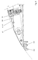
- Fig. 1
- eine teilgeschnittene Ansicht einer Verriegelungsanordnung mit Blickrichtung in Fahrtrichtung
- Fig. 2
- eine Draufsicht auf Fig. 1
- Fig. 3
- ein Verriegelungsgehäuse in Seitenansicht
- Fig. 4
- Fig. 3 mit abgesenktem Verriegelungszapfen
- Fig. 5
- die Verriegelungsanordnung mit der zweiten Verriegelungseinrichtung in Parkposition
- Fig. 6
- die Verriegelungsanordnung mit der ersten und zweiten Verriegelungseinrichtung in Parkposition
- Fig. 7
- einen horizontal schwenkbaren Schwenkarm in U-Form
- Fig. 8
- einen vertikal schwenkbaren Schwenkarm in U-Form
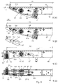
- Fig. 9
- eine erste Ausführung mit einem verschiebbaren Bolzenträger in verschiedenen Verriegelungspositionen,
- Fig. 10
- eine zu Fig. 1 (C) alternative Position der Verriegelungen,
- Fig. 11
- eine Ausführungsform mit einem festen Steckbolzen.
- Fig. 1
- a partially sectioned view of a locking arrangement looking in the direction of travel
- Fig. 2
- a plan view of Fig. 1st
- Fig. 3
- a lock housing in side view
- Fig. 4
- Fig. 3 with lowered locking pin
- Fig. 5
- the locking arrangement with the second locking device in parking position
- Fig. 6
- the locking arrangement with the first and second locking device in parking position
- Fig. 7
- a horizontal swiveling arm in U-shape
- Fig. 8
- a vertically swiveling arm in U-shape
- Fig. 9
- a first embodiment with a displaceable bolt carrier in different locking positions,
- Fig. 10
- an alternative to Fig. 1 (C) position of the locks,
- Fig. 11
- an embodiment with a solid locking pin.
Die in Fig. 1 und Fig. 2 skizzierte Verriegelungsanordnung zeigt drei verschiedene Verriegelungseinrichtungen gemeinsam in ihren jeweiligen Haltepositionen. Dabei sind nicht jeweils alle Elemente eingezeichnet, um die Übersichtlichkeit der Abbildungen zu verbessern.The outlined in Fig. 1 and Fig. 2 locking arrangement shows three different Locking devices together in their respective holding positions. Not all elements are drawn in each case for the sake of clarity to improve the pictures.
Die erste Verriegelungsanordnung ist am Ende eines Querträgers QT angeordnet, welcher zumindest im Bereich der Verriegelungsanordnung als ein U-förmiges Profil mit Flächen QT-O, QT-R und QT-U ausgeführt und in Fahrtrichtung LR, d.h. gegenüber der Wand QT-R zumindest teilweise, vorzugsweise überwiegend oder vollständig offen ist.The first locking arrangement is arranged at the end of a cross member QT, which at least in the region of the locking arrangement as a U-shaped Profile with surfaces QT-O, QT-R and QT-U executed and in the direction of travel LR, i. opposite the wall QT-R at least partially, preferably is predominantly or completely open.
Ein Verriegelungsgehäuse VG1 enthält als Verriegelungselement der ersten Verriegelungseinrichtung einen Drehzapfen VK, welcher vertikal über die obere Fläche des Verriegelungsgehäuses VG1 hinausragt und in eine untere Öffnung eines Eckbeschlags EB1 eines Containers hineinragt. Durch Verdrehen des Zapfens um eine vertikale Achse mittels des Verriegelungshebels VH wird der Beschlag mit dem Verriegelungsgehäuse verriegelt. Drehzapfen-Verriegelungen sind allgemein bekannt und gebräuchlich, so dass auf Details der Drehzapfenverriegelung hier nicht weiter eingegangen wird.A locking housing VG1 contains as a locking element of the first Locking device a pivot VK, which vertically over the upper Surface of the lock housing VG1 protrudes and into a lower opening a corner fitting EB1 of a container protrudes. By twisting the Pivot about a vertical axis by means of the locking lever VH is the Fitting locked with the lock housing. Trunnion latches are commonly known and commonly used, so on details the trunnion lock will not be discussed here.
In dem Gehäuse ist zusätzlich eine dritte Verriegelungseinrichtung mit einem Steckbolzen SB1 untergebracht. Der Steckbolzen ragt horizontal entgegen der Fahrtrichtung über das Verriegelungsgehäuse VG1 hinaus und kann in eine stirnseitige Öffnung eines nicht abgeschrägten Eckbeschlags eingreifen.In the housing is additionally a third locking device with a Locking pin SB1 housed. The socket pin projects horizontally against the Direction of travel beyond the lock housing VG1 and can in a frontal opening of a non-bevelled corner fitting engage.
Das Verriegelungsgehäuse VG1 ist an einem Schwenkarm gehalten, welcher aus zwei parallelen horizontalen Armplatten A1, A2 aufgebaut ist, welche mit dem Verriegelungsgehäuse vorzugsweise verschweißt sind. Der Schwenkarm ist um eine vertikale Schwenkachse SA in Pfeilrichtung AS horizontal aus der skizzierten Halteposition von erster und dritter Verriegelungseinrichtung verschwenkbar. Die Armplatten A1, A2 verlaufen innerhalb des Profils des Querträgers QT parallel zu dessen horizontalen Wänden QT-O, QT-U und liegen an diesen an oder diesen mit geringem Abstand gegenüber.The lock housing VG1 is held on a pivot arm, which is constructed of two parallel horizontal arm plates A1, A2, which with the locking housing are preferably welded. The swivel arm is about a vertical pivot axis SA in the direction of arrow AS horizontally from the sketched holding position of the first and third locking device pivotable. The arm plates A1, A2 extend within the profile of the cross member QT parallel to its horizontal walls QT-O, QT-U and are applied on this or this with a small distance opposite.
Ein zweiter horizontaler Steckbolzen SB2 als Verriegelungselement einer zweiten Verriegelungseinrichtung ist fest mit einem plattenförmigen Träger T2 verbunden. Der Träger T2 weist eine der Rückwand QT-R des Querträgerprofils abgewandte Kante auf, welche schräg gegen die Rückwand QT-R verläuft und in der skizzierten Halteposition der zweiten Verriegelungseinrichtung innerhalb eines zulässigen Durchdrehkreisbogens um den Königszapfen des Fahrgestell-Auflagers verläuft und sich dabei eng an den Kreisbogen anschmiegt. Der zweite Steckbolzen SB2 ragt horizontal über die durch die Rückwand QT-R des Querträgers gebildete Anschlagkante für eine Container-Stirnkante hinaus und kann in einen abgeschrägten Eckschlag eines 45'-HC-Containers eingreifen. A second horizontal locking pin SB2 as a locking element of a second locking device is fixed to a plate-shaped carrier T2 connected. The carrier T2 has one of the rear wall QT-R of the cross member profile remote edge, which runs obliquely against the rear wall QT-R and in the sketched holding position of the second locking device within a permissible spin arc around the kingpin of the chassis support runs and thereby closely conforms to the circular arc. The second plug SB2 protrudes horizontally over the through the rear wall QT-R the cross member formed stop edge for a container end edge addition and can interfere with a beveled corner of a 45 'HC container.
Der Träger T2 ist um die mit dem Schwenkarm gemeinsame vertikale Schwenkachse SA schwenkbar. Da der zweite horizontale Steckbolzen SB2 nur um eine geringe Differenz ca. DS= 85 mm näher zur Mittellängsebene des Fahrgestells liegt als der erste horizontale Steckbolzen SB1 und der Drehzapfen VK, liegt der zweite Träger in der skizzierten Position eng an dem Verriegelungsgehäuse VG1 an, so dass nicht ohne weiteres eine Verschwenkung des Trägers T2 im Uhrzeigersinn über die skizzierte Position hinaus relativ zu dem Verriegelungsgehäuse möglich ist. Eine solche relative Verschwenkung wird in der vorteilhaften skizzierten Ausführung dadurch ermöglicht, dass der Träger T2 ein Langloch LL um die Schwenkwelle SW der Schwenkachse SA aufweist und durch Führung des Langlochs auf der Schwenkwelle vom Verriegelungsgehäuse weg radial verschoben und in der verschobenen Position in Pfeilrichtung TS verschwenkt werden kann.The carrier T2 is about the vertical pivot axis with the pivot arm SA swiveling. Since the second horizontal pin SB2 only to a small difference about DS = 85 mm closer to the central longitudinal plane of the chassis is located as the first horizontal pin SB1 and the pivot VK, the second carrier is in the sketched position close to the locking housing VG1, so that not readily a pivoting of the carrier T2 clockwise beyond the outlined position relative to the latch housing is possible. Such relative pivoting will occur in the advantageous sketched embodiment thereby allows the carrier T2 a Long hole LL has around the pivot shaft SW of the pivot axis SA and by guiding the slot on the pivot shaft from the lock housing away radially displaced and in the shifted position in the direction of arrow TS can be pivoted.
Die Welle SW ist im skizzierten Beispiel zweiseitig abgeflacht ausgeführt. Eine relative radiale Verschiebung des Schwenkarms A1, A2 nach außen ermöglicht gleichfalls das relative Verschwenken.The wave SW is carried out in the example sketched two sides flattened. A allows relative radial displacement of the pivot arm A1, A2 to the outside likewise the relative pivoting.
Die Trägerplatte T2 liegt in bezüglich der vertikalen Schwenkachse SA achsialer Richtung beabstandet zwischen den Armplatten A1, A2 und parallel zu diesen. Zur Stabilisierung der verschiedenen Verriegelungseinrichtungen gegen vertikale Kräfte sind horizontale Stützplatten SP1, SP2 mit der Rückwand QT-R des Querträgers verschweißt, welche in achsialer Richtung zwischen sich den Träger 2 und gegen die horizontalen Wände QT-O, QT-U des Querträgers die Armplatten A2 bzw. A1 eng einschließen. Im Bereich der Schwenkwelle SW ist eine achsiale Abstützung durch Distanzscheiben DS zwischen Trägerplatte T2 und Armplatten A1, A2 gegeben, wobei die Distanzscheiben auch als Stufenscheiben ausgebildet sein und in gegenüber dem Wellendurchmesser größere Bohrungen der Armplatten A1, A2 anliegen können. The support plate T2 is in relation to the vertical pivot axis SA achsialer Direction spaced between the arm plates A1, A2 and parallel to these. To stabilize the various locking devices against vertical forces are horizontal support plates SP1, SP2 with the rear wall QT-R the cross member welded, which in the axial direction between the Beam 2 and against the horizontal walls QT-O, QT-U of the cross member the Tightly enclose arm plates A2 or A1. In the area of the pivot shaft SW an axial support by spacers DS between support plate T2 and arm plates A1, A2 given, the spacers also as stepped discs be formed and larger in relation to the shaft diameter Holes of the arm plates A1, A2 can rest.
Die Steckbolzen SB1, SB2 sind in Fig. 1 und Fig. 2 als in der skizzierten Halteposition parallel zur Längsrichtung LR des Fahrgestells ausgerichtet eingezeichnet. Zur Anpassung an die Kreisbogenbewegung um die Schwenkachse können die Steckbolzen aber auch annähernd tangential um die Schwenkachse ausgebildet sein, um beim Einschwenken in die Öffnungen der Eckbeschläge möglichst geringes seitliches Spiel in den Öffnungen aufzuweisen.The locking pins SB1, SB2 are in Fig. 1 and Fig. 2 as in the sketched holding position drawn aligned parallel to the longitudinal direction LR of the chassis. To adapt to the circular arc movement about the pivot axis However, the socket pin can also approximately tangential to the pivot axis be formed to pivot in the openings of the corner fittings show as little side play in the openings.
Während bei der Benutzung der zweiten Verriegelungseinrichtung mit dem in einen abgeschrägten Eckbeschlag eingreifenden Steckbolzen SB2 das Verriegelungsgehäuse VG1 weit weggeschwenkt sein muss, um innerhalb des zulässigen Durchdrehkreises DR zu liegen, kann bei Benutzung der dritten Verriegelungseinrichtung das Wegschwenken der zweiten Verriegelungseinrichtung auf einen kleinen Schwenkwinkel beschränkt werden, der ausreicht, um den zweiten Steckbolzen vollständig in Fahrtrichtung vor die durch die Rückwand QT-R gebildete Anschlagfläche zu verlegen. Die Trägerplatte T2 mit dem zweiten Bolzen SB2 kann dann zwischen den Armplatten A1, A2 verbleiben. Dies ermöglicht die Ausbildung des Schwenkarms als in der Halteposition in Fahrtrichtung durch eine weitere Platte abgeschlossenes oder einstückiges U-Profil mit geringerer Empfindlichkeit gegen Scherverformungen durch vertikale Krafteinwirkung auf die erste oder dritte Verriegelungseinrichtung.While in the use of the second locking device with the in a bevelled corner fitting engaging pin SB2 the lock housing VG1 has to be widely swung to within the permissible range By turning circle DR lie, when using the third locking device the pivoting away of the second locking device be limited to a small tilt angle sufficient to the second locking pin completely in the direction of travel in front of the through the rear wall To lay QT-R formed stop surface. The support plate T2 with the second bolt SB2 can then remain between the arm plates A1, A2. This allows the formation of the pivot arm as in the holding position in Direction of travel through another plate completed or one-piece U-profile with lower sensitivity to shear deformation due to vertical Force on the first or third locking device.
Bei Benutzung der ersten Verriegelungseinrichtung mit dem Drehzapfen ist die Stellung der anderen Verriegelungseinrichtungen im wesentlichen unerheblich, da der Boden des Containers oberhalb der Steckbolzen liegt.When using the first locking device with the pivot is the Position of the other locking devices essentially irrelevant, because the bottom of the container is above the socket pin.
Die in Fig. 5 mit unterbrochener Linie in einer möglichen Parkposition innerhalb der Vertikalprojektion des Schwenkarms bzw. dessen Platten A1, A2 liegende zweite Verriegelungseinrichtung verdeutlicht in dieser Position auch die Möglichkeiten, den Schwenkarm an seiner hier in Fahrtrichtung liegenden Seite zwischen Platten A1, A2 zu einer U-Form zu schließen oder den Schwenkarm z.B. als unten offene U-Form auszuführen und um eine horizontale Achse nach oben weg bzw. von oben über die Parkposition der zweiten Verriegelungseinrichtung zu schwenken. Fig. 7 zeigt im Schnitt mit Blickrichtung quer zur Fahrzeuglängsachse eine Variante mit horizontal verschwenkbarem Schwenkarm SWH in entgegen der Fahrtrichtung offener U-Form, Fig. 8 einen vertikal verschwenkbaren Schwenkarm SWH mit nach unten offener U-Form. Einzelne Elemente sind dabei, insbesondere zu der Ausführung nach Fig. 8 in konstruktiven Details anzupassen, was in Fig. 7 und Fig. 8 noch nicht berücksichtigt ist.The in Fig. 5 with a broken line in a possible parking position within the vertical projection of the pivot arm or its plates A1, A2 lying second locking device also illustrates in this position the possibilities the swivel arm on his here in the direction of travel side between plates A1, A2 to close a U-shape or the swivel arm e.g. to perform as U-shape open at the bottom and after a horizontal axis up and away from above the parking position of the second locking device to pan. Fig. 7 shows in section with a view transverse to the vehicle longitudinal axis a variant with horizontally pivoting arm SWH in opposite to the direction of travel open U-shape, Fig. 8 a vertically pivotable Swing arm SWH with downwardly open U-shape. Separate Elements are, in particular to the embodiment of FIG. 8 in constructive Details to adapt, which is not yet considered in Fig. 7 and Fig. 8.
Die Fig. 5 zeigt in Draufsicht eine Situation, in welcher die dritte Verriegelungseinrichtung mit dem ersten Steckbolzen SB1 in eine stirnseitige Öffnung eines nicht abgeschrägten Eckbeschlags EB3 z.B. eines 20'- oder 40'-HC-Containers eingreift und die Trägerplatte T2 um einen geringen Schwenkwinkel gegen die in Fig. 2 skizzierte Position verschwenkt ist, aber unverändert von den Armplatten A1, A2 vollständig überdeckt ist. Die Trägerplatte T2 mit dem Steckbolzen SB2 kann aber auch um einen größeren Winkel vollständig aus dem Bereich des Schwenkarms herausgeschwenkt sein.Fig. 5 shows in plan view a situation in which the third locking device with the first locking pin SB1 in an end opening of a non-tapered corner fitting EB3 e.g. a 20 'or 40' HC container engages and the support plate T2 by a small tilt angle against the 2 sketched position is pivoted, but unchanged from the arm plates A1, A2 is completely covered. The support plate T2 with the locking pin SB2 can also be completely out of range at a greater angle be swung out of the swivel arm.
Demgegenüber ist bei der in Fig. 6 skizzierten Situation, in welcher der an der Trägerplatte T2 befestigte zweite Steckbolzen SB2 in eine stirnseitige Öffnung eines abgeschrägten Eckbeschlags EB2 eingreift, der Schwenkarm mit dem Verriegelungsgehäuse VG1 um nahezu 180° gegen die in Fig. 2 skizzierte Halteposition verschwenkt und teilweise in das in Fahrtrichtung offene Profil des Querträgers eingerückt ist. Eine Überdeckung der Parkposition des Hebelarms mit der Halteposition der zweiten Verriegelungseinrichtung ist nicht gegeben. In contrast, in the case sketched in Fig. 6, in which the at the Support plate T2 attached second plug pin SB2 in a frontal opening a bevelled corner fitting EB2 engages the swivel arm with the Lock housing VG1 by almost 180 ° against the sketched in Fig. 2 Holding position pivoted and partially open in the direction of travel profile of the cross member is engaged. An overlap of the parking position of the lever arm with the holding position of the second locking device is not given.
Die Verriegelungseinrichtungen können in ihren jeweiligen Haltepositionen vorteilhafterweise durch Sicherungseinrichtungen gehalten sein, wobei insbesondere durch die horizontale Schwenkbewegung um die vertikale Schwenkachse SA eine Sicherung durch Absperren der Schwenkbewegung besonders vorteilhaft ist. Eine solche Sicherung kann beispielsweise durch einen in fluchtende Sicherungsbohrungen SH von Querträger und Trägerplatte T2 bzw. Schwenkarm A1, A2 einsteckbaren Sicherungsbolzen SI erfolgen.The locking devices can in their respective holding positions be advantageously held by securing devices, in particular by the horizontal pivoting movement about the vertical pivot axis SA a fuse by blocking the pivoting movement especially is advantageous. Such a fuse can, for example, by a flush in Locking holes SH of cross member and support plate T2 or Swivel arm A1, A2 insertable safety pin SI.
Der Querträger QT erstreckt sich mit seiner Rückwand QT-R seitlich im wesentlichen bis zu dem Steckbolzen SB2, so dass eine hohe Aussteifung gegen Vertikalkräfte gegeben ist. Der Querträger kann vor dem Steckbolzen SB2 enden oder diesen umgreifen. Eine zusätzliche Abstützung der Verriegelungseinrichtungen erfolgt durch die in den Endbereichen des Querträgers vorgesehenen Stützplatten SP1, SP2.The cross member QT extends laterally with its rear wall QT-R substantially up to the socket pin SB2, allowing a high stiffener against Vertical forces is given. The cross member may end in front of the socket pin SB2 or embrace this. An additional support of the locking devices is provided by the provided in the end regions of the cross member Support plates SP1, SP2.
Die Fig. 3 und Fig. 4 zeigen eine vorteilhafte Ausführungsform eines Verriegelungsgehäuses VG1, welches durch Verschwenken des Drehzapfens VK in einen Bereich zwischen oberer und unterer Begrenzungsfläche des Verriegelungsgehäuses, die vertikal nicht über die Armplatten A1 und A2 nach unten bzw. oben überstehen, in eine besonders flache Form gebracht und damit auch weit in das in Fahrtrichtung offene Profil des Querträgers eingeschwenkt werden kann.FIGS. 3 and 4 show an advantageous embodiment of a locking housing VG1, which by pivoting the pivot VK in an area between upper and lower boundary surfaces of the lock housing, the vertical not over the arm plates A1 and A2 down or survive above, brought in a particularly flat shape and thus also be pivoted far into the open in the direction of travel profile of the cross member can.
Vorteilhaft bei der in Fig. 3 und Fig. 4 skizzierten Ausführung ist insbesondere auch, dass der Verriegelungszapfen, welcher in einem Zapfenträger gehalten und drehbar geführt ist, um eine horizontale Kippachse KA kippbar ist und dabei in der in Fig. 3 skizzierten aufrechten Position durch einen lösbaren Riegel RI abgestützt ist. Advantageous in the sketched in Fig. 3 and Fig. 4 embodiment is particular also, that the locking pin, which held in a pin carrier and is rotatably guided, about a horizontal tilting axis KA is tiltable and thereby in the outlined in Fig. 3 upright position by a releasable latch RI is supported.
Der Riegel ist gemäß dem skizzierten Beispiel durch einen dem ersten Steckbolzen SB1 abgewandten und mit diesem fest verbundenen und um eine vertikale Achse BA im Verriegelungsgehäuse schwenkbaren Fortsatz gebildet, welcher sich auf dem Boden des Verriegelungsgehäuses abstützt und in einer Aussparung AU des Zapfenträgers ZT einliegt. Die Aussparung AU sichert zugleich den Steckbolzen SB1 gegen Verschwenkung um die Achse BA. Durch anhebendes Kippen des Zapfenträgers um die Kippachse KA wird der Steckbolzen SB1 zur Verschwenkung um die Achse BA freigegeben und nach Verschwenken des Bolzens und des Riegels RI um die Achse BA gibt, wie in Fig. 4 skizziert, der Riegel den Zapfenträger zum Einschwenken des Zapfens in das Gehäuse frei.The bolt is according to the example outlined by a the first locking pin SB1 facing away from and firmly connected to this and a vertical Axis BA formed in the locking housing pivotable extension, which is supported on the bottom of the locking housing and in a Recess AU of the pin ZT rests. The recess AU secures at the same time the plug pin SB1 against pivoting about the axis BA. By Lifting tilting of the pin carrier about the tilting axis KA becomes the socket pin SB1 released for pivoting about the axis BA and after pivoting of the bolt and the bolt RI about the axis BA, as in FIG. 4 sketched, the bolt the pin carrier for pivoting the pin in the Housing free.
Die in Fig. 9 bis Fig. 11 skizzierten Ausführungsformen sind weitgehend an die bereits anhand der Fig. 1 bis Fig. 6 erläuterte bevorzugte Ausführungsform angelehnt. Die diesbezüglichen vorangehenden Ausführungen gelten im Umfang der Übereinstimmungen im wesentlichen auch für die nachfolgend noch im einzelnen erläuterten weiteren Ausführungen. Insbesondere sind die Konstruktion des Querträgers QT als in Fahrtrichtung zumindest teilweise offenes Profil, der Aufbau eines Schwenkarms aus zwei parallelen Platten A1, A2 und ein Verriegelungsgehäuse mit einem absenkbaren Drehzapfen als erste Verriegelungseinrichtung übernommen.The embodiments outlined in FIGS. 9 to 11 are largely similar to FIGS already based on the Fig. 1 to Fig. 6 explained preferred embodiment ajar. The relevant previous explanations are valid in scope the correspondences essentially also for the following in detail explained further comments. In particular, the construction of the cross member QT as in the direction of travel at least partially open profile, the Structure of a pivoting arm of two parallel plates A1, A2 and a lock housing with a lowerable pivot as the first locking device accepted.
In den Beispielen nach Fig. 9 und Fig. 10 ist ferner ähnlich dem schwenkbaren Bolzenträger aus den vorangehenden Beispielen ein hier aber linear verschiebbarer Bolzenträger plattenförmig ausgebildet und zwischen Stützplatten SP1, SP2 stabil gehalten.Further, in the examples of FIGS. 9 and 10, it is similar to the pivotable one Bolzenträger from the preceding examples here but a linearly displaceable Bolzenträger plate-shaped and between support plates SP1, SP2 kept stable.
In Übereinstimmung mit den vorangehenden Beispielen sei als erste Verriegelungseinrichtung ein häufig als Twist-Lock bezeichneter, vertikal in einen Container-Eckbeschlag von unten eingreifender und durch Drehung verriegelbarer Zapfen verstanden, wogegen als zweite und dritte Verriegelungseinrichtung horizontale Steckbolzen dienen.In accordance with the preceding examples let be as the first locking device an often referred to as a twist-lock, vertically in a container corner fitting engaging from below and lockable by rotation Pins understood, whereas as the second and third locking device serve horizontal locking pins.
Eine vorteilhafte Ausführungsform ist in Fig. 9 in unterschiedlichen Positionen und Ansichten skizziert, wobei hier die zweite und dritte Verriegelungseinrichtung in Form eines Steckbolzens SB2 identisch sind. Der Steckbolzen ist auf einem Bolzenträger BT angeordnet, welcher als Schiebling in einer quer zur Längsrichtung LR des Fahrgestells verlaufenden Schieberichtung SR verschiebbar ist und durch diese Verschiebung aus dem Querträger entnommen und/oder in wenigstens zwei in Schieberichtung verschiedenen Positionen festgelegt werden kann. Die Festlegung kann beispielsweise durch einen Sicherungsbolzen SIA erfolgen, welcher durch Öffnungen im Querträger und im Bolzenträger durchgreift.An advantageous embodiment is in Fig. 9 in different positions and views outlined, in which case the second and third locking device in the form of a pin SB2 are identical. The locking pin is open a bolt carrier BT arranged, which as a slide in a transverse to Slidable longitudinal direction LR of the chassis extending sliding direction SR is and removed by this shift from the cross member and / or set in at least two different positions in the sliding direction can be. The determination can for example by a safety pin SIA, which through openings in the cross member and the bolt carrier be upheld.
Beispielsweise befindet sich der Bolzenträger BT in der Skizze nach Fig. 9 (A) in einer Arbeitsposition zur Halterung eines überlangen 45'-HC-Containers als einem zweiten Containertyp mit abgeschrägten Eckbeschlägen. Der seitliche Abstand D1 des Steckbolzens SB2 von der Mittelebene ME des Fahrgestells beträgt dann ca. 1045 mm. Durch Lösen des Sicherungsbolzens SIA und Verschieben des Bolzenträgers in Schieberichtung SR nach außen und Festlegen in der in Fig. 9 (B) skizzierten Arbeitsposition liegt der Steckbolzen SB2 um eine Abstandsdifferenz DS weiter außen in einem Abstand D2 von der Mittellängsebene ME des Fahrgestells mit D2 ca. 1130 mm und kann als dritte Verriegelungseinrichtung zur Halterung eines Standard-HC-Containers als dritten Containertyp dienen.For example, the bolt carrier BT is in the sketch of FIG. 9 (A). in a working position for holding an oversized 45 'HC container as a second container type with bevelled corner fittings. The lateral Distance D1 of the pin SB2 from the center plane ME of the chassis is then about 1045 mm. By loosening the safety bolt SIA and moving of the bolt carrier in sliding direction SR to the outside and fixing in the working position outlined in Fig. 9 (B), the socket pin SB2 is one Distance difference DS further outward at a distance D2 from the central longitudinal plane ME of the chassis with D2 about 1130 mm and can be used as a third locking device for mounting a standard HC container as the third container type serve.
Das Verriegeln und Entriegeln eines Containers zweiten oder dritten Typs auf dem Fahrgestell erfolgt durch Verschieben des Querträgers in Pfeilrichtung TS parallel zur Fahrzeuglängsrichtung LR, ohne dass ein Verschwenken des Bolzenträgers BT erforderlich ist. Eine solche Vorgehensweise zum Verriegeln und Entriegeln ist auch bei den vorausgehend beschriebenen Ausführungen möglich und vorteilhaft, wobei dann die eventuell gegebene Verschwenkbarkeit des den Bolzen tragenden Arm nur noch zum Wechsel der Verriegelungseinrichtung dient. Die Längsverschiebbarkeit des vorderen Querträgers in Längsführungen ist an sich bekannt und kann vorteilhafterweise hydraulisch betätigt sein.Locking and unlocking a second or third type container The chassis is made by moving the cross member in the direction of arrow TS parallel to the vehicle longitudinal direction LR, without pivoting the bolt carrier BT is required. Such a procedure for locking and Unlocking is also possible with the previously described embodiments and advantageous, in which case the possibly given pivotability of the the bolt-carrying arm only to change the locking device serves. The longitudinal displacement of the front cross member in longitudinal guides is known per se and can advantageously be operated hydraulically be.
Die erste Verriegelungseinrichtung mit einem vertikal in einen Eckbeschlag eines Containers ersten Typs eingreifenden Steckzapfen VK in einem Verriegelungsgehäuse VG ist in Fig. 9 (A) und Fig. 9 (B) in einer Parkposition durch einen zweiten Sicherungsbolzen SIP festgelegt. Hierbei ist aus Ausführungsformen der vorangehenden Beispiele übernommen, dass der Querträger wenigstens abschnittsweise in Fahrtrichtung, d. h. der Querträger-Rückwand QTR abgewandt, oben ist und das an einem Schwenkarm befestigte Verriegelungsgeäuse VG der ersten Verriegelungseinrichtung in der Parkstellung zwischen oberer QTO und unterer QTU Platte des Querträgers und innerhalb des Durchdrehkreises DR um den Königszapfen des Fahrgestell-Auflagers liegt. Hierbei kann, wie zu diesen vorangehenden Beispielen beschrieben, der Verriegelungszapfen aus der aufrechten Position in das Verriegelungsgehäuse abgeschwenkt sein.The first locking device with a vertical in a corner fitting of a Containers first type engaging plug VK in a lock housing VG is in a parking position by a in Fig. 9 (A) and Fig. 9 (B) second safety pin SIP set. This is from embodiments taken from the preceding examples, that the cross member at least sections in the direction of travel, d. H. the crossmember rear wall QTR facing away, above and attached to a pivoting arm locking housing VG of the first locking device in the parking position between upper QTO and lower QTU plate of the cross member and within the spin circle DR is located around the kingpin of the chassis support. in this connection can, as described in these previous examples, the locking pin swung from the upright position in the locking housing be.
Zum Wechsel auf die erste Verriegelungseinrichtung wird diese aus der in Fig. 9 (A) und Fig. 9 (B) skizzierten Parkposition durch Verschwenken des Schwenkarms um die vertikale Schwenkachse SA in die in Fig. 9 (C) in Draufsicht und in Fig. 9 (D) in Frontansicht skizzierte Arbeitsposition geschwenkt (AS) und der Verriegelungszapfen über das Verriegelungsgehäuse, VG hinaus in die aufrechte Position gebracht. Mittels des Hebels VH kann der Zapfen VK um seine vertikale Achse gedreht werden.To change to the first locking device, this is from the in Fig. 9 (A) and Fig. 9 (B) sketched parking position by pivoting the Swing arm about the vertical pivot axis SA in the in Fig. 9 (C) in plan view and pivoted in Fig. 9 (D) sketched in front view working position (AS) and the locking pin beyond the lock housing, VG out put in the upright position. By means of the lever VH, the pin VK to be rotated about its vertical axis.
Der Bolzenträger BT, der zwischen Fig. 9 (B) und Fig. 9 (C) isoliert dargestellt ist, kann hierzu aus dem Querträger entnommen und in seine in Fig. 9 (C) und Fig. 9 (D) skizzierte Parkposition zwischen oberer und unterer Platte QTO, QTU des Querträgers gebracht werden. In der isolierten Darstellung des Bolzenträgers sind deutlich zwei Durchbrüche TL1, TL2 durch die Trägerplatte zu erkennen, welche zur Festlegung des Bolzenträgers in den beiden Arbeitspositionen nach Fig. 9 (A) und Fig. 9 (B) dienen. Eine Aussparung TF umgreift in der Arbeitsposition nach Fig. 9 (A) und der Parkposition nach Fig. 9 (C) die Schwenkachse SA. Die dem Bolzen abgewandte Öffnung der Aussparung kann zur Sicherung gegen unbeabsichtigtes Ausfallen überbrückt oder abgeschlossen sein.The bolt carrier BT, which is shown isolated between Fig. 9 (B) and Fig. 9 (C) is, this can be taken from the cross member and in his in Fig. 9 (C) and Fig. 9 (D) sketched parking position between upper and lower plate QTO, QTU be brought to the cross member. In the isolated representation of the bolt carrier clearly two openings TL1, TL2 can be seen through the carrier plate, which for fixing the bolt carrier in the two working positions as shown in Fig. 9 (A) and Fig. 9 (B). A recess TF surrounds in the working position of Fig. 9 (A) and the parking position of Fig. 9 (C), the pivot axis SA. The bolt facing away from the opening of the recess can for Fuse against unintentional failure bridged or completed be.
Die seitliche Verschiebbarkeit des Bolzenträgers aus der Position nach Fig. 9 (A) mit vollständig innerhalb eines Durchdrehkreises DR mit Radius 2040 mm um den Königszpafen des Auflagers des Fahrgestells auf einem Zugfahrzeug liegender Verriegelungsanordnung führt durch die seitliche Verschiebung des Bolzenträgers in die Position nach Fig. 9 (B) zu einem nur geringen Überstand des Bolzenträgers über dessen Position nach Fig. 9 (A). Hierdurch kann in der Position nach Fig. 9 (B) auch ein 45'-HC-Container mit rechtwinkligen nicht abgeschrägten Eckbeschlägen unter Einhaltung der Durchdrehkreis-Beschränkung gehalten werden, indem der Querträger QT insgesamt um das Längsmaß des Überstandes entgegen der Fahrtrichtung LR verschoben positioniert wird. Der daraus resultierende Überstand des Containers am Fahrzeugheck ist mit ca. 60 mm im Regelfall tolerabel. The lateral displaceability of the bolt carrier from the position according to FIG. 9 (A) with complete within a spin circle DR with radius 2040 mm around the king seat of the landing gear of the undercarriage on a towing vehicle lying latching arrangement leads through the lateral displacement of the Bolzenträgers in the position of FIG. 9 (B) to a slight projection of the bolt carrier via its position according to FIG. 9 (A). This can be done in the Position of FIG. 9 (B) also a 45 'HC container with rectangular non-bevelled Corner fittings in compliance with the spin circle restriction held by the cross member QT total around the Longitudinal distance of the supernatant against the direction of travel LR shifted positioned becomes. The resulting supernatant of the container at the rear of the vehicle is tolerable with approx. 60 mm as a rule.
Aus der Frontansicht nach Fig. 9 (D) sind weitere den bisher genannten Ausführungsformen der Erfindung ähnliche Konstruktionsdetails ersichtlich. Der Schwenkarm, an welchem das Verriegelungsgehäuse VG außen befestigt ist, kann aus zwei vertikal beabstandeten Armplatten A1, A2 bestehen, aber auch zusätzliche vertikale Wandabschnitte zwischen den Armplatten A1, A2 zur Aussteifung enthalten. Horizontale Stützplatten SP1, SP2, welche mit der Rückwandplatte QTR verbunden, insbesondere verschweißt sind, stützen sowohl die Armplatten A1, A2 des das Verriegelungsgehäuse tragenden Schwenkarms als auch den Bolzenträger BT in dessen Arbeitspositionen nach Fig. 9 (A), 9 (B) vertikal ab. Durchbrüche ALA, ALP in den Platten A1, A2 dienen zur Festlegung des Schwenkarms in der Arbeitsposition nach Fig. 9 (C), (D) bzw. der Parkposition nach Fig. 9 (A), (B).From the front view of Fig. 9 (D) are further the previously mentioned Embodiments of the invention similar construction details visible. The swivel arm, on which the lock housing VG is externally attached can be made of two vertically spaced arm plates A1, A2 exist, but also additional vertical Wall sections between the arm plates A1, A2 included for stiffening. Horizontal support plates SP1, SP2, which with the back plate QTR connected, in particular welded, support both the arm plates A1, A2 of the locking housing bearing arm and the bolt carrier BT in its working positions of Fig. 9 (A), 9 (B) vertically from. Breakthroughs ALA, ALP in plates A1, A2 serve to define the Swing arm in the working position of Fig. 9 (C), (D) or the parking position according to Fig. 9 (A), (B).
In Fig. 10 ist eine Abwandlung gezeigt, in welcher in einer zu Fig. 9 (C) entsprechenden Arbeitsposition der ersten Verriegelungseinrichtung mit dem vertikalen Zapfen der verschiebbare Bolzenträger mit dem Steckbolzen SB nicht aus dem Querträger herausgezogen, sondern in der Position nach Fig. 9 (A) verblieben ist und das Verriegelungsgehäuse seitlich davon liegt Dabei ist angenommen, dass das Verriegelungsgehäuse VG mit dem Verriegelungszapfen in richtigem Abstand zur Fahrzeugmittelebene ME, welcher bei den üblichen Containerbeschlägen gleich D2 ist, seitlich neben dem in der Arbeitsposition nach Fig.9 (C) befindlichen Bolzenträger Platz findet. Falls die Geometrie des Verriegelungsgehäuses dies nicht zulässt, kann auch vorgesehen sein, den Bolzenträger über die Arbeitsposition nach Fig. 9 (C) hinaus in einer näher zur Mittelebene ME hin liegenden Parkposition zu verschieben und/oder das Verriegelungsgehäuse nicht genau seitlich des Bolzenträgers sondern in Längsrichtung LR und zur Mittelebene ME hin versetzt anzuordnen und/oder das Verriegelungsgehäuse an der dem Bolzenträger zuweisenden Ecke abzuschrägen. Das Verriegelungsgehäuse ist wiederum am Schwenkarm um die Schwenkachse SA in Pfeilrichtung AS schwenkbar und kann aus der skizzierten Arbeitsposition, in welcher durch vertikal in Eckbeschläge eingreifende Verriegelungszapfen VK ein erster Container-Typ (ISO) gehalten werden kann, in eine Parkposition der in Fig. 9 (A), (B) skizzierten Art verschwenkt werden, um mit dem Steckbolzen SB2 in einer seiner beiden Arbeitspositionen entsprechend Fig. 9 (A), (B) einen HC-Container des zweiten oder dritten Container-Typs zu halten. Die Ausführung nach Fig. 10 ist auch in Verbindung mit einem zusätzlich um die Schwenkachse SA schwenkbaren Bolzenträger BT vorteilhaft realisierbar.In Fig. 10, a modification is shown in which in one of Fig. 9 (C) corresponding Working position of the first locking device with the vertical Do not pin the sliding bolt carrier with the plug pin SB pulled out of the cross member, but in the position of FIG. 9 (A) is left and the lock housing lies to the side of it is assumed that the lock housing VG with the locking pin in the correct distance to the vehicle center plane ME, which in the usual Container fittings equal to D2, laterally next to the one in the working position Figure 9 (C) located bolt carrier finds place. If the geometry of the Locking housing does not allow, can also be provided, the Bolzenträger beyond the working position of FIG. 9 (C) out in a closer to Center plane ME lying park position to move and / or the lock housing not exactly at the side of the bolt carrier but in the longitudinal direction LR and offset towards the center plane ME and / or the locking housing beveled on the Corner facing the bolt carrier. The lock housing is in turn on the pivot arm about the pivot axis SA pivotable in the direction of arrow AS and can from the sketched working position, in which by vertically engaging in Eckbeschläge locking pin VK a first container type (ISO) can be kept in one Parking position of Fig. 9 (A), (B) outlined manner are pivoted to the plug pin SB2 in one of its two working positions accordingly Fig. 9 (A), (B) to a HC container of the second or third container type hold. The embodiment of Fig. 10 is also in conjunction with an additional pivotable about the pivot axis SA Bolzenträger BT advantageously realized.
Während in den Ausführungen nach Fig. 1 bis Fig. 6 und nach Fig. 9 und Fig. 10 der Steckbolzen SB2, welcher zur Haltung von Containern zweiter Art dient, auf einem relativ zum Querträger verlagerbaren Bolzenträger befestigt ist und in eine Parkposition und/oder eine weitere Arbeitsposition verlagerbar ist, sieht eine in Fig. 11 skizzierte Ausführungsform vor, einen Steckbolzen SB in zur Halterung von Containern zweiten Typs geeigneter Arbeitsposition fest am Querträger anzuordnen und die Halterung von Containern dritten Typs mittels eines Steckbolzens SB1 vorzunehmen, welcher aus einer Parkposition in eine Arbeitsposition mit Abstand D2 zur Mittelebene ME schwenkbar ist. Der Steckbolzen SB1 kann vorteilhafterweise wie in vorangehenden Ausführungen mit einem Verriegelungsgehäuse VG1 eines Twist-Lock-Steckzapfens verbunden sein. Der Fußpunkt des Steckbolzens SB1, welcher im skizzierten Beispiel an der Rückwand GR des Kombi-Verriegelungsgehäuses VG1 liegt, ist gegenüber dem Fußpunkt des festen Steckbolzens SB entgegen der Fahrtrichtung wenigstens um die Bolzenlänge BL des Steckbolzens SB versetzt. Das Kombi-Verriegelungsgehäuse VG1 ist um die Schwenkachse SA aus der skizzierten Arbeitsstellung in eine Parkstellung entsprechend Fig. 9 (A), (B) verschwenkbar. While in the embodiments according to FIG. 1 to FIG. 6 and according to FIG. 9 and FIG. 10 of the plug pin SB2, which serves to hold containers of the second kind, is mounted on a relative to the cross member displaceable bolt carrier and in a parking position and / or another working position is movable, sees an outlined in Fig. 11 embodiment before, a pin SB in the Mounting of containers of the second type suitable working position firmly on To arrange cross member and the holder of containers of the third type by means of a plug pin SB1 make, which from a parking position in a Working position with distance D2 to the center plane ME is pivotable. The socket pin SB1 can advantageously with as in previous embodiments with a lock housing VG1 connected to a twist-lock spigot be. The base of the pin SB1, which in the example sketched the rear wall GR of the combination lock housing VG1 is opposite the base of the fixed pin SB against the direction of travel at least offset by the bolt length BL of the plug pin SB. The combination lock housing VG1 is outlined about the pivot axis SA Working position in a parking position according to Fig. 9 (A), (B) pivotable.
In Fig. 9 sind auch vorteilhafte relative Positionen bezüglich der Mittellängsebene ME veranschaulicht. Der Abstand D3 der Schwenkachse des Schwenkarms der ersten Verriegelungseinrichtung liegt vorzugsweise zwischen 60 % und 90 % des Abstands D1 des Steckbolzens SB2 von dieser Mittellängsebene. Die erste Verriegelungseinheit befindet sich in ihrer Parkposition vorteilhafterweise in einem Abstand D4 von der Mittellängsebene, der bei weniger als 50 %, vorzugsweise zwischen 20 % und 40 % von D1 liegt.In Fig. 9 are also advantageous relative positions with respect to the central longitudinal plane ME illustrates. The distance D3 of the pivot axis of the pivot arm the first locking device is preferably between 60% and 90 % of the distance D1 of the pin SB2 from this central longitudinal plane. The first locking unit is located in its parking position advantageously at a distance D4 from the central longitudinal plane that is less than 50%, preferably between 20% and 40% of D1.
Die vorstehend und die in den Ansprüchen angegebenen sowie die den Abbildungen entnehmbaren Merkmale sind sowohl einzeln als auch in verschiedener Kombination vorteilhaft realisierbar. Die Erfindung ist nicht auf die beschriebenen Ausführungsbeispiele beschränkt, sondern im Rahmen fachmännischen Könnens in mancherlei Weise abwandelbar, sofern durch die Ansprüche abgedeckt. Insbesondere können die Verriegelungseinrichtungen im Detail in verschiedener Weise, insbesondere auch mit Elementen aus dem Stand der Technik, aufgebaut sein. Teile der Anordnung können auch quer zur Fahrtrichtung entlang der Querträger verschiebbar, insbesondere auch teleskopierbar in diesen geführt sein, um verschiedene Seitenabstände einzustellen und/oder in eine Parkposition verschiebbar zu sein. Die Ausbildung des Bolzenträgers ist nicht auf die plattenförmige Gestaltung beschränkt. Der Schwenkarm der ersten Verriegelungseinrichtung kann auch quer zur Längsrichtung verschiebbar sein.The above and those specified in the claims and the figures removable features are both single and in different Combination advantageously feasible. The invention is not limited to those described Embodiments limited, but in the context of expert Can be modified in many ways, as long as covered by the claims. In particular, the locking devices in detail in various Way, especially with elements of the state of Technology, be built. Parts of the arrangement can also be transverse to the direction of travel displaceable along the cross member, in particular also telescopic in be guided to set different side distances and / or in a parking position to be displaced. The training of the bolt carrier is not limited to the plate-shaped design. The swivel arm of the first Locking device can also be displaced transversely to the longitudinal direction be.
Claims (30)
- Arrangement for locking different types of container on a chassis by means of different locking devices, which are fixed to a common crossmember (QT) which can be positioned variously in the longitudinal direction of the chassis, depending on the container type,a) a first locking device for locking a first container type bearing, on a swinging arm (A1, A2), a locking pin (VK) which engages in vertically in a corner fitting (EB1) of the container when in a locking positionb) a second locking device for locking a second container type having a first lock pin (SB2), which engages horizontally in a corner fitting (EB2) of the container when in a locking position,c) the second locking device lying within a predefined maximum full rotation circle (DR) about a vertical bearing axis of the chassis when in the locking position,
characterized in thatd) by pivoting the swinging arm (A1, A2, SWV) about a vertical pivot axis (SA) the first locking device can be moved from the locking position into a first parking position which, with simultaneous locking of a second container type by means of the second locking device, lies within the maximum full rotation circle, ande) the pivot axis (SA) of the swinging arm (A1, A2) is offset towards the central longitudinal plane with respect to the first lock pin (SB2). - Arrangement according to Claim 1, characterized in that the distance (D3) of the pivot axis (SA) from the central longitudinal plane of the chassis is between 60% and 90% of the distance of the first lock pin (SB2) from the central longitudinal plane.
- Arrangement according to Claim 1 or 2, characterized in that the first parking position of the first locking device is pivoted towards the central longitudinal plane of the container with respect to its locking position.
- Arrangement according to Claim 3, characterized in that, in its parking position, the first locking device is spaced apart from the central longitudinal plane by between 10% and 50% of the distance (D1) of the first lock pin (SB2).
- Arrangement according to one of Claims 1 to 4, characterized in that, in its parking position, the swinging arm (A1, A2) and/or first locking device can move at least partly into an opening in the crossmember (QT) that is open towards the front side (Fig. 6).
- Arrangement according to one of Claims 1 to 5, characterized in that the locking pin (VK) can be lowered in the first locking device.
- Arrangement according to one of Claims 1 to 6, characterized in that the corner fitting (EB2) of the second container type is bevelled and the second locking device, in its locking position, ends at a distance spaced apart from the side dimension of the container towards the central longitudinal plane of the chassis.
- Arrangement according to Claim 7, characterized by a third locking device which, in its locking position, engages horizontally in a corner fitting of a third container type by means of a second lock pin (SB1), the engagement position of the lock pin of the third locking device being spaced apart further (DS) from the central longitudinal plane of the chassis than the engagement position of the lock pin (SB2) of the second locking device.
- Arrangement according to one of Claims 1 to 8, characterized in that the first lock pin (SB2) is arranged in a position that is fixed relative to the crossmember (QT).
- Arrangement according to one of Claims 1 to 8, characterized in that the first lock pin (SB2) is arranged on a pin carrier (T2) of the second locking device, whose position relative to the crossmember can be varied and which has a locking position relative to the crossmember.
- Arrangement according to Claim 10, characterized in that the locking positions of the swinging arm (A1, A2) carrying the first locking device and of the pin carrier (T2) of the second locking device at least partly overlap relative to the common crossmember.
- Arrangement according to Claim 10 or 11, characterized in that the pin carrier (T2) can be pivoted about a vertical pivot axis (SA).
- Arrangement according to Claim 12, characterized in that the second locking device can be displaced radially with respect to the vertical pivot axis (SA).
- Arrangement according to one of Claims 1 to 13, characterized in that the second locking device, when in a parking position, is covered or surrounded by the swinging arm (A1, A2) of the first locking device (Fig. 5).
- Arrangement according to one of Claims 12 to 14,
characterized in that the pivot axes of pin carrier (T2) and swinging arm (A1, A2) coincide. - Arrangement according to one of Claims 12 to 15, characterized in that swinging arm (A1, A2) and pin carrier (T2) occupy separate sections in the axial direction with respect to the pivot axis (SA).
- Arrangement according to Claim 16, characterized in that at least part of the separate sections is spaced apart axially and supporting devices (SP1, SP2) are provided on the crossmember in the region of the axial spacings.
- Arrangement according to Claim 10 or 11, characterized in that the pin carrier (BT) can be displaced transversely with respect to the longitudinal direction of the vehicle and can be locked such that it cannot be pivoted at at least one locking distance from a chassis centre plane.
- Arrangement according to Claim 18, characterized in that the pin carrier (BT) that can be displaced transversely can be locked at two different locking distances from the chassis centre plane.
- Arrangement according to Claim 18 or 19, characterized in that the pin carrier (BT) can be displaced into a parking position that is different from a locking position.
- Arrangement according to one of Claims 18 to 20, characterized in that the pin carrier (BT) can be detached from the crossmember (QT).
- Arrangement according to one of Claims 8 to 21, characterized in that the first locking device is arranged on the swinging arm (A1, A2) together with the third locking device.
- Arrangement according to Claim 22, characterized in that the lock pin (SB1) of the third locking device can be pivoted and, in the process, actuates a securing element (TI) for the locking pin (VK) in the locking position of the latter.
- Arrangement according to one of Claims 8 to 23, characterized in that the second lock pin (SB1) of the third locking device projects from a rear wall of a locking housing and, in the locking position of the third locking device, points rearward, substantially parallel to the vehicle longitudinal axis, and in that the base of the second lock pin (SB1) on the housing rear wall is offset with respect to the base of the first lock pin (SB2) in the longitudinal direction of the chassis by at least the length of the first lock pin (SB2) (Fig. 11).
- Arrangement according to one of Claims 20 to 24, characterized in that the crossmember (QT) can be displaced and locked in the longitudinal direction of the chassis even when there is a second container type resting on the chassis.
- Arrangement for locking different types of container on a chassis by means of different locking devices, which are fixed to a common crossmember (QT) which can be positioned variously in the longitudinal direction of the chassis, depending on the container type,f) a first locking device for locking a first container type bearing, on a swinging arm (SWV), a locking pin (VK) which engages in vertically in a corner fitting (EB1) of the container when in a locking position,g) a second locking device for locking a second container type having a first lock pin (SB2), which engages horizontally in a corner fitting (EB2) of the container when in a locking position,h) the second locking device lying within a predefined maximum full rotation circle (DR) about a vertical bearing axis of the chassis when in the locking position,i) by pivoting the swinging arm (SWV) about a horizontal pivot axis, it being possible to move the first locking device from the locking position into a first parking position which, with simultaneous locking of a second container type by means of the second locking device, lies within the maximum full rotation circle,
characterized in thatj) the horizontal pivot axis (SWA) of the swinging arm is offset towards the central longitudinal plane with respect to the first lock pin (SB2). - Arrangement according to Claim 26, characterized in that the swinging arm (SWV) is designed in the form of a U profile which is open at the bottom and which, in the locking position of a third locking device, surrounds the second locking device (SB2) laterally in its parking position (Fig. 8).
- Arrangement according to one of Claims 1 to 27, characterized in that the locking devices can be fixed in their locking positions by at least one securing element (SI).
- Arrangement according to one of Claims 1 to 28, characterized in that the crossmember is designed to be substantially continuous as far as the first lock pin (SB2) of the opposite second locking device.
- Chassis having an arrangement according to one of Claims 1 to 29.
Priority Applications (1)
| Application Number | Priority Date | Filing Date | Title |
|---|---|---|---|
| DK02021520T DK1300285T3 (en) | 2001-10-02 | 2002-09-26 | Device for holding different types of containers on a chassis |
Applications Claiming Priority (4)
| Application Number | Priority Date | Filing Date | Title |
|---|---|---|---|
| DE2001148704 DE10148704C1 (en) | 2001-10-02 | 2001-10-02 | Assembly to lock and secure a container, at a truck chassis, has a lateral carrier with an adjustable position and locking mechanisms for different container types to grip their corner fittings |
| DE10148704 | 2001-10-02 | ||
| DE10232561 | 2002-07-18 | ||
| DE10232561A DE10232561A1 (en) | 2001-10-02 | 2002-07-18 | Arrangement for holding different types of containers on a chassis |
Publications (2)
| Publication Number | Publication Date |
|---|---|
| EP1300285A1 EP1300285A1 (en) | 2003-04-09 |
| EP1300285B1 true EP1300285B1 (en) | 2005-06-08 |
Family
ID=26010283
Family Applications (1)
| Application Number | Title | Priority Date | Filing Date |
|---|---|---|---|
| EP02021520A Expired - Lifetime EP1300285B1 (en) | 2001-10-02 | 2002-09-26 | Arrangement for locking of different types of containers on a chassis |
Country Status (6)
| Country | Link |
|---|---|
| EP (1) | EP1300285B1 (en) |
| AT (1) | ATE297326T1 (en) |
| DE (2) | DE10232561A1 (en) |
| DK (1) | DK1300285T3 (en) |
| ES (1) | ES2242809T3 (en) |
| PT (1) | PT1300285E (en) |
Families Citing this family (5)
| Publication number | Priority date | Publication date | Assignee | Title |
|---|---|---|---|---|
| EP1621399A1 (en) * | 2004-07-28 | 2006-02-01 | Holger Stuht | Device for locking containers on a vehicle frame at different heights |
| DE102004045665B4 (en) * | 2004-09-18 | 2008-01-31 | Jost-Werke Gmbh & Co. Kg | Cross member for frontal installation in a chassis |
| DE102005050928B4 (en) * | 2005-10-21 | 2009-04-09 | Fahrzeugwerk Bernard Krone Gmbh | Chassis for containers, superstructures and the like cargo containers |
| EP2379369B1 (en) * | 2008-12-17 | 2014-02-26 | Volvo Lastvagnar AB | Carrier device for coupling different kinds of payload bodies |
| EP4335696A1 (en) | 2023-10-19 | 2024-03-13 | Hiab AB | A locking assembly |
Family Cites Families (8)
| Publication number | Priority date | Publication date | Assignee | Title |
|---|---|---|---|---|
| DE9114904U1 (en) * | 1991-11-30 | 1993-03-25 | Schulz, Gerd, 3501 Zierenberg, De | |
| DE19606263A1 (en) * | 1995-03-22 | 1996-09-26 | Jost Werke Ag | Device for locking container to motor vehicle chassis |
| DE29606845U1 (en) * | 1996-04-16 | 1996-07-04 | Alli Frischdienst Zentrale Nor | Subframe for a truck for the transport of swap bodies |
| DE20010144U1 (en) * | 1999-06-29 | 2000-12-14 | Metternich Metallbau Gmbh R | Device for fastening an excessively long container on a transport vehicle |
| NL1013424C2 (en) * | 1999-10-29 | 2001-05-02 | Contar B V | Container transport vehicle, especially trailer, includes container locking device mounted on rotatable telescopic arm |
| DE20012977U1 (en) * | 2000-07-27 | 2001-02-08 | Metternich Metallbau Gmbh R | Device for fastening an excessively long container on a transport vehicle |
| DE10047093A1 (en) * | 2000-09-21 | 2002-05-02 | Jost Werke Gmbh & Co Kg | Device to lock container to vehicle chassis has first locking element positioned at larger distance to its carrier when in rest position |
| DE10108096A1 (en) * | 2001-02-19 | 2002-09-12 | Juergen Ehring | Locking system for cargo on vehicles and its components |
-
2002
- 2002-07-18 DE DE10232561A patent/DE10232561A1/en not_active Withdrawn
- 2002-09-26 AT AT02021520T patent/ATE297326T1/en not_active IP Right Cessation
- 2002-09-26 PT PT02021520T patent/PT1300285E/en unknown
- 2002-09-26 DK DK02021520T patent/DK1300285T3/en active
- 2002-09-26 ES ES02021520T patent/ES2242809T3/en not_active Expired - Lifetime
- 2002-09-26 EP EP02021520A patent/EP1300285B1/en not_active Expired - Lifetime
- 2002-09-26 DE DE50203323T patent/DE50203323D1/en not_active Expired - Lifetime
Also Published As
| Publication number | Publication date |
|---|---|
| DE10232561A1 (en) | 2004-02-05 |
| DE50203323D1 (en) | 2005-07-14 |
| ES2242809T3 (en) | 2005-11-16 |
| ATE297326T1 (en) | 2005-06-15 |
| PT1300285E (en) | 2005-09-30 |
| EP1300285A1 (en) | 2003-04-09 |
| DK1300285T3 (en) | 2005-08-22 |
Similar Documents
| Publication | Publication Date | Title |
|---|---|---|
| EP2261066B1 (en) | Trailer device | |
| DE3642938C2 (en) | ||
| EP0695655A1 (en) | Towing connection and lock device | |
| DE19934739B4 (en) | Steering device for a vehicle | |
| EP0688687A1 (en) | Lifting device | |
| EP3666591A1 (en) | Container lock, front extension of a chassis with such a container lock and locking arrangement | |
| DE3322551C2 (en) | Intermediate piece for switching off the lateral mobility of the lower links of an agricultural tractor | |
| EP1300285B1 (en) | Arrangement for locking of different types of containers on a chassis | |
| DE4413444A1 (en) | Loading ramp for vehicle | |
| EP0985563B1 (en) | Lifting device | |
| EP1354790B1 (en) | Foldable stanchion with locking device | |
| EP1544003B1 (en) | Trailer hitch for motor vehicles | |
| EP0844208B1 (en) | Vehicle jack | |
| DE10047093A1 (en) | Device to lock container to vehicle chassis has first locking element positioned at larger distance to its carrier when in rest position | |
| DE2736222C3 (en) | Lift catch | |
| DE19520893A1 (en) | Headrest folding device | |
| EP0518208A1 (en) | Device for changing over the steering of a self-propelling crane | |
| DE3147543A1 (en) | Extendible drawbar | |
| EP0388363B1 (en) | Trailerhitch for vehicles | |
| EP0545019A1 (en) | Device for latching a container on a vehicle frame | |
| DE102007015331A1 (en) | Runge for commercial vehicle superstructures | |
| DE10148704C1 (en) | Assembly to lock and secure a container, at a truck chassis, has a lateral carrier with an adjustable position and locking mechanisms for different container types to grip their corner fittings | |
| EP2583881B1 (en) | Steering device for a camera dolly and camera dolly with steering device | |
| DE3240919A1 (en) | Railway hopper wagon | |
| DE102021133431A1 (en) | Folding device for rear vehicle carrier and rear vehicle carrier with such a folding device |
Legal Events
| Date | Code | Title | Description |
|---|---|---|---|
| PUAI | Public reference made under article 153(3) epc to a published international application that has entered the european phase |
Free format text: ORIGINAL CODE: 0009012 |
|
| AK | Designated contracting states |
Kind code of ref document: A1 Designated state(s): AT BE BG CH CY CZ DE DK EE ES FI FR GB GR IE IT LI LU MC NL PT SE SK TR |
|
| AX | Request for extension of the european patent |
Extension state: AL LT LV MK RO SI |
|
| 17P | Request for examination filed |
Effective date: 20031009 |
|
| AKX | Designation fees paid |
Designated state(s): AT BE BG CH CY CZ DE DK EE ES FI FR GB GR IE IT LI LU MC NL PT SE SK TR |
|
| 17Q | First examination report despatched |
Effective date: 20040202 |
|
| GRAP | Despatch of communication of intention to grant a patent |
Free format text: ORIGINAL CODE: EPIDOSNIGR1 |
|
| GRAS | Grant fee paid |
Free format text: ORIGINAL CODE: EPIDOSNIGR3 |
|
| GRAA | (expected) grant |
Free format text: ORIGINAL CODE: 0009210 |
|
| AK | Designated contracting states |
Kind code of ref document: B1 Designated state(s): AT BE BG CH CY CZ DE DK EE ES FI FR GB GR IE IT LI LU MC NL PT SE SK TR |
|
| PG25 | Lapsed in a contracting state [announced via postgrant information from national office to epo] |
Ref country code: CZ Free format text: LAPSE BECAUSE OF FAILURE TO SUBMIT A TRANSLATION OF THE DESCRIPTION OR TO PAY THE FEE WITHIN THE PRESCRIBED TIME-LIMIT Effective date: 20050608 Ref country code: TR Free format text: LAPSE BECAUSE OF FAILURE TO SUBMIT A TRANSLATION OF THE DESCRIPTION OR TO PAY THE FEE WITHIN THE PRESCRIBED TIME-LIMIT Effective date: 20050608 Ref country code: IE Free format text: LAPSE BECAUSE OF FAILURE TO SUBMIT A TRANSLATION OF THE DESCRIPTION OR TO PAY THE FEE WITHIN THE PRESCRIBED TIME-LIMIT Effective date: 20050608 Ref country code: SK Free format text: LAPSE BECAUSE OF FAILURE TO SUBMIT A TRANSLATION OF THE DESCRIPTION OR TO PAY THE FEE WITHIN THE PRESCRIBED TIME-LIMIT Effective date: 20050608 Ref country code: EE Free format text: LAPSE BECAUSE OF FAILURE TO SUBMIT A TRANSLATION OF THE DESCRIPTION OR TO PAY THE FEE WITHIN THE PRESCRIBED TIME-LIMIT Effective date: 20050608 |
|
| REG | Reference to a national code |
Ref country code: GB Ref legal event code: FG4D Free format text: NOT ENGLISH |
|
| REG | Reference to a national code |
Ref country code: CH Ref legal event code: EP |
|
| REF | Corresponds to: |
Ref document number: 50203323 Country of ref document: DE Date of ref document: 20050714 Kind code of ref document: P |
|
| REG | Reference to a national code |
Ref country code: IE Ref legal event code: FG4D Free format text: LANGUAGE OF EP DOCUMENT: GERMAN |
|
| REG | Reference to a national code |
Ref country code: DK Ref legal event code: T3 |
|
| GBT | Gb: translation of ep patent filed (gb section 77(6)(a)/1977) |
Effective date: 20050815 |
|
| PG25 | Lapsed in a contracting state [announced via postgrant information from national office to epo] |
Ref country code: BG Free format text: LAPSE BECAUSE OF FAILURE TO SUBMIT A TRANSLATION OF THE DESCRIPTION OR TO PAY THE FEE WITHIN THE PRESCRIBED TIME-LIMIT Effective date: 20050908 Ref country code: GR Free format text: LAPSE BECAUSE OF FAILURE TO SUBMIT A TRANSLATION OF THE DESCRIPTION OR TO PAY THE FEE WITHIN THE PRESCRIBED TIME-LIMIT Effective date: 20050908 Ref country code: SE Free format text: LAPSE BECAUSE OF FAILURE TO SUBMIT A TRANSLATION OF THE DESCRIPTION OR TO PAY THE FEE WITHIN THE PRESCRIBED TIME-LIMIT Effective date: 20050908 |
|
| PG25 | Lapsed in a contracting state [announced via postgrant information from national office to epo] |
Ref country code: AT Free format text: LAPSE BECAUSE OF NON-PAYMENT OF DUE FEES Effective date: 20050926 Ref country code: CY Free format text: LAPSE BECAUSE OF FAILURE TO SUBMIT A TRANSLATION OF THE DESCRIPTION OR TO PAY THE FEE WITHIN THE PRESCRIBED TIME-LIMIT Effective date: 20050926 |
|
| PG25 | Lapsed in a contracting state [announced via postgrant information from national office to epo] |
Ref country code: LU Free format text: LAPSE BECAUSE OF NON-PAYMENT OF DUE FEES Effective date: 20050930 Ref country code: MC Free format text: LAPSE BECAUSE OF NON-PAYMENT OF DUE FEES Effective date: 20050930 |
|
| REG | Reference to a national code |
Ref country code: PT Ref legal event code: SC4A Effective date: 20050727 |
|
| REG | Reference to a national code |
Ref country code: ES Ref legal event code: FG2A Ref document number: 2242809 Country of ref document: ES Kind code of ref document: T3 |
|
| REG | Reference to a national code |
Ref country code: IE Ref legal event code: FD4D |
|
| ET | Fr: translation filed | ||
| PLBE | No opposition filed within time limit |
Free format text: ORIGINAL CODE: 0009261 |
|
| STAA | Information on the status of an ep patent application or granted ep patent |
Free format text: STATUS: NO OPPOSITION FILED WITHIN TIME LIMIT |
|
| 26N | No opposition filed |
Effective date: 20060309 |
|
| PG25 | Lapsed in a contracting state [announced via postgrant information from national office to epo] |
Ref country code: CH Free format text: LAPSE BECAUSE OF NON-PAYMENT OF DUE FEES Effective date: 20060930 Ref country code: LI Free format text: LAPSE BECAUSE OF NON-PAYMENT OF DUE FEES Effective date: 20060930 |
|
| REG | Reference to a national code |
Ref country code: CH Ref legal event code: PL |
|
| REG | Reference to a national code |
Ref country code: DE Ref legal event code: R082 Ref document number: 50203323 Country of ref document: DE Representative=s name: GERHARD WEBER, DE |
|
| REG | Reference to a national code |
Ref country code: DE Ref legal event code: R082 Ref document number: 50203323 Country of ref document: DE Representative=s name: BAUR & WEBER PATENTANWAELTE PARTG MBB, DE Effective date: 20120402 Ref country code: DE Ref legal event code: R082 Ref document number: 50203323 Country of ref document: DE Representative=s name: BAUR & WEBER PATENTANWAELTE, DE Effective date: 20120402 Ref country code: DE Ref legal event code: R081 Ref document number: 50203323 Country of ref document: DE Owner name: SCHMITZ CARGOBULL GOTHA GMBH, DE Free format text: FORMER OWNER: SCHMITZ GOTHA FAHRZEUGWERKE GMBH, 99867 GOTHA, DE Effective date: 20120402 |
|
| REG | Reference to a national code |
Ref country code: DE Ref legal event code: R082 Ref document number: 50203323 Country of ref document: DE Representative=s name: BAUR & WEBER PATENTANWAELTE PARTG MBB, DE Ref country code: DE Ref legal event code: R082 Ref document number: 50203323 Country of ref document: DE Representative=s name: BAUR & WEBER PATENTANWAELTE, DE |
|
| REG | Reference to a national code |
Ref country code: FR Ref legal event code: PLFP Year of fee payment: 14 |
|
| PGFP | Annual fee paid to national office [announced via postgrant information from national office to epo] |
Ref country code: GB Payment date: 20150922 Year of fee payment: 14 Ref country code: ES Payment date: 20150923 Year of fee payment: 14 Ref country code: PT Payment date: 20150923 Year of fee payment: 14 Ref country code: FI Payment date: 20150921 Year of fee payment: 14 |
|
| PGFP | Annual fee paid to national office [announced via postgrant information from national office to epo] |
Ref country code: FR Payment date: 20150923 Year of fee payment: 14 |
|
| PGFP | Annual fee paid to national office [announced via postgrant information from national office to epo] |
Ref country code: DK Payment date: 20150923 Year of fee payment: 14 |
|
| PGFP | Annual fee paid to national office [announced via postgrant information from national office to epo] |
Ref country code: IT Payment date: 20150925 Year of fee payment: 14 |
|
| REG | Reference to a national code |
Ref country code: DK Ref legal event code: EBP Effective date: 20160930 |
|
| PG25 | Lapsed in a contracting state [announced via postgrant information from national office to epo] |
Ref country code: FI Free format text: LAPSE BECAUSE OF NON-PAYMENT OF DUE FEES Effective date: 20160926 |
|
| GBPC | Gb: european patent ceased through non-payment of renewal fee |
Effective date: 20160926 |
|
| PG25 | Lapsed in a contracting state [announced via postgrant information from national office to epo] |
Ref country code: PT Free format text: LAPSE BECAUSE OF NON-PAYMENT OF DUE FEES Effective date: 20170327 |
|
| REG | Reference to a national code |
Ref country code: FR Ref legal event code: ST Effective date: 20170531 |
|
| PG25 | Lapsed in a contracting state [announced via postgrant information from national office to epo] |
Ref country code: FR Free format text: LAPSE BECAUSE OF NON-PAYMENT OF DUE FEES Effective date: 20160930 Ref country code: GB Free format text: LAPSE BECAUSE OF NON-PAYMENT OF DUE FEES Effective date: 20160926 |
|
| PG25 | Lapsed in a contracting state [announced via postgrant information from national office to epo] |
Ref country code: IT Free format text: LAPSE BECAUSE OF NON-PAYMENT OF DUE FEES Effective date: 20160926 |
|
| PG25 | Lapsed in a contracting state [announced via postgrant information from national office to epo] |
Ref country code: DK Free format text: LAPSE BECAUSE OF NON-PAYMENT OF DUE FEES Effective date: 20160930 |
|
| PGFP | Annual fee paid to national office [announced via postgrant information from national office to epo] |
Ref country code: NL Payment date: 20170925 Year of fee payment: 16 Ref country code: BE Payment date: 20170925 Year of fee payment: 16 |
|
| PG25 | Lapsed in a contracting state [announced via postgrant information from national office to epo] |
Ref country code: ES Free format text: LAPSE BECAUSE OF NON-PAYMENT OF DUE FEES Effective date: 20160927 |
|
| REG | Reference to a national code |
Ref country code: ES Ref legal event code: FD2A Effective date: 20181123 |
|
| REG | Reference to a national code |
Ref country code: NL Ref legal event code: MM Effective date: 20181001 |
|
| REG | Reference to a national code |
Ref country code: BE Ref legal event code: MM Effective date: 20180930 |
|
| PG25 | Lapsed in a contracting state [announced via postgrant information from national office to epo] |
Ref country code: NL Free format text: LAPSE BECAUSE OF NON-PAYMENT OF DUE FEES Effective date: 20181001 |
|
| PG25 | Lapsed in a contracting state [announced via postgrant information from national office to epo] |
Ref country code: BE Free format text: LAPSE BECAUSE OF NON-PAYMENT OF DUE FEES Effective date: 20180930 |
|
| PGFP | Annual fee paid to national office [announced via postgrant information from national office to epo] |
Ref country code: DE Payment date: 20210930 Year of fee payment: 20 |
|
| REG | Reference to a national code |
Ref country code: DE Ref legal event code: R071 Ref document number: 50203323 Country of ref document: DE |