EP1300284A2 - Container locking device - Google Patents
Container locking device Download PDFInfo
- Publication number
- EP1300284A2 EP1300284A2 EP02021414A EP02021414A EP1300284A2 EP 1300284 A2 EP1300284 A2 EP 1300284A2 EP 02021414 A EP02021414 A EP 02021414A EP 02021414 A EP02021414 A EP 02021414A EP 1300284 A2 EP1300284 A2 EP 1300284A2
- Authority
- EP
- European Patent Office
- Prior art keywords
- locking
- locking unit
- arrangement
- arrangement according
- carrier
- Prior art date
- Legal status (The legal status is an assumption and is not a legal conclusion. Google has not performed a legal analysis and makes no representation as to the accuracy of the status listed.)
- Granted
Links
Images


Classifications
-
- B—PERFORMING OPERATIONS; TRANSPORTING
- B60—VEHICLES IN GENERAL
- B60P—VEHICLES ADAPTED FOR LOAD TRANSPORTATION OR TO TRANSPORT, TO CARRY, OR TO COMPRISE SPECIAL LOADS OR OBJECTS
- B60P1/00—Vehicles predominantly for transporting loads and modified to facilitate loading, consolidating the load, or unloading
- B60P1/64—Vehicles predominantly for transporting loads and modified to facilitate loading, consolidating the load, or unloading the load supporting or containing element being readily removable
- B60P1/6418—Vehicles predominantly for transporting loads and modified to facilitate loading, consolidating the load, or unloading the load supporting or containing element being readily removable the load-transporting element being a container or similar
- B60P1/6481—Specially adapted for carrying different numbers of container or containers of different sizes
-
- B—PERFORMING OPERATIONS; TRANSPORTING
- B60—VEHICLES IN GENERAL
- B60P—VEHICLES ADAPTED FOR LOAD TRANSPORTATION OR TO TRANSPORT, TO CARRY, OR TO COMPRISE SPECIAL LOADS OR OBJECTS
- B60P7/00—Securing or covering of load on vehicles
- B60P7/06—Securing of load
- B60P7/13—Securing freight containers or forwarding containers on vehicles
- B60P7/132—Securing freight containers or forwarding containers on vehicles twist-locks for containers or frames
Definitions
- the invention relates to a locking arrangement for holding containers on a chassis.
- Chassis for holding exchangeable containers can be used with one Step frame can be designed as a so-called Gooseneck chassis and thereby using high cube (HC) containers within the framework of the given regulations Pick up the Gooseneck tunnel in the container floor.
- HC high cube
- step frames it is also possible to transport containers with a flat floor surface different designs of locking arrangements attached to the chassis, from below using a lockable pivot in fittings of the container, known.
- EP 0 337 011 A1 shows a carrying device which is one horizontal axis is pivotally mounted on the chassis and two locking devices has different distances from the pivot axis have and can optionally be pivoted into the carrying position.
- DE 296 16 083 U1 has a height-adjustable locking device described for swap bodies, in which a first locking housing is firmly connected to a support for a deeper support and a second locking housing for the deeper support next to the side the first locking housing and by pivoting about a joint can be placed on the first housing to provide higher support to build.
- a locking arrangement is known from DE 195 38 915 A1, in which a vertical prismatic guide is firmly connected to a chassis is. In the guide, a slide can be moved vertically and in two different ways Height positions can be locked. The slider is laterally offset a lock housing attached with a pivot lock, which is height adjustable with the slider. A similar locking arrangement is known from DE 296 22 249 U1.
- DE 197 55 638 C2 shows a locking arrangement, in which a further development DE 195 38 915 A1 the locking housing itself within the vertical guide lies and can be fixed in two height positions.
- DE 19 66 501 A1 describes a device for locking transport containers described on vehicles in which a locking insert between an upper working position and a lower retracted position is movable. There is a protrusion on a vertical plate of the insert formed, which engages in a recess of a rear wall plate and supports the insert vertically. A releasable locking member holds the projection in the Recess. A second working position is not planned.
- the present invention has for its object a simple structure and manageable, inexpensive locking arrangement for mounting of containers in two different height positions.
- the locking arrangement according to the invention enables in particular in the upper position the stable vertical support of the locking unit in one Support bearing arrangement by pivoting the locking unit around a horizontal axis or by displacement with a horizontal movement component, preferably by a combination of both forms of movement can be moved from the upper stop position without a vertically supporting additional element such as a plug pin or a Intermediate pipe section must be relocated.
- the vertical support can therefore very stable and structurally simple and takes up little space be and the handling is particularly easy.
- Under the pivot vertical direction is a pivoting movement with predominantly vertical pivot movement component of a spaced from the pivot axis Support of the locking unit.
- that forms Swivel bearing itself a second support.
- the two spaced supports advantageously close the support surface in the horizontal direction of a container to be held.
- a combination of a pivoting movement and one is particularly advantageous Movement with a horizontal movement component of the locking unit.
- the locking unit in at least the upper, preferably also the lower holding position through coordinated design of the locking unit, Carrier arrangement and, if necessary, connecting guide elements against it translational displacement is form-fitting, and that this is fixing only by pivoting the locking unit around a horizontal one Axis through a minimum angle of e.g. > 45 ° can be canceled.
- the locking unit e.g. in the typical Execution as a pivot lock already by engaging in the Container fitting against swiveling on the horizontal swivel axis is locked, the locking unit is when the container is attached and locked also safe against high vertical and horizontal forces the carrier assembly held.
- the pivoting of the locking unit around a horizontal axis can advantageously be used according to a development of the invention the locking unit is lower than the lower holding position
- To shift parking position which is preferably a swivel a stop position is made by more than 180 °.
- the carrier arrangement has two parallel vertical plates, which the locking unit enclose between themselves and in each of which a backdrop is formed, in which a connected to the locking unit Set element is guided.
- the backdrop element can preferably also be used as Swivel shaft for pivoting the locking device by one serve horizontal axis.
- the backdrop element can e.g. a preferred be releasably connected to the locking unit bolt, rod, etc.
- the Guidance in the link arrangement can be advantageous in the way with the pivoting be combined that endpoints and / or reversal points one Set the slide at the same time as pivot bearings for the pivoting.
- the locking unit can advantageously be guided through the link arrangement at the same time as protection against loss and / or quick theft serve the locking unit.
- the one delimited by the two vertical, preferably parallel plates Space is advantageously in the direction facing away from the cross member largely open, which in particular allows easy access to the locking unit for their adjustment and / or for actuating the lock and during the displacement of the locking unit between the holding positions or possibly a parking position a movement of the locking device beyond the plate edges is possible.
- the locking device is advantageously a pivot lock, especially designed with a twistable pivot.
- the locking unit can in both stop positions and possibly the parking position by one or several securing elements secured in their position relative to the carrier arrangement his.
- the securing elements are preferably under spring tension held in their securing position and, for example, as on the carrier assembly attached spring bolt with a in a counter opening of the locking unit engaging locking bolt.
- FIGS. 1 to 7 instructs QT on a cross member whose end facing away from the central longitudinal axis of a chassis is a carrier arrangement which consists essentially of two vertical support plates TP1, TP2 exists, which e.g. to the vertical side surfaces of the as a rectangular profile trained cross member and welded to the cross member are.
- the type of attachment of the support plates to the cross member is not of further importance below.
- the two support plates run flat and parallel to each other and delimit in the direction of travel FA, i.e. a receiving space in the longitudinal direction of the chassis, within which a locking unit has different positions can take.
- Shaped backdrop tracks are in the support plates TP1, TP2 KB formed in which a guide bolt running in the direction of travel FB is performed as a backdrop element.
- the support plates have horizontal top edges POK on.
- One of the support plates preferably the support plate lying in the direction of travel TP1 carries a spring bolt FR with a safety bolt, which depends on Position of the locking unit in one of several safety openings intervenes.
- the locking unit consists of a Locking housing, which has a lockable locking pin contains.
- the locking pin protrudes with one at the top of one Locking bolt RB located, flattened mushroom-shaped head PZ on both sides beyond the upper contact surface AF of the locking housing and engages when placing a container in a downward opening of a Container corner fitting EB.
- Using a KN knob at the lower end of the locking bolt RB the entire pin can be turned through 90 ° and locks the corner fitting.
- Using a clamping nut SPM on a thread the locking pin can be pulled down and the container fitting can be clamped against the locking housing.
- a locking latch RF prevents the clamping nut from being unintentionally loosened SPM.
- the locking principle described by means of a braced vertical locking pin is known and in use.
- the locking housing comprises essentially two parallel vertical side plates SP1, SP2, one horizontal upper support plate AP, a side support plate STP and a lower counter plate, on which the clamping nut is supported.
- the side plates SP1, SP2 run parallel to the support plates TP1, TP2 within the confined space and limited to the side Distance from these.
- the lower counter plate UP again runs between the two side plates SP1, SP2.
- the support plate AP and the support plate STP are preferably made in one piece as an angled plate. Platen with support plate, side plates and counter plate are advantageous welded together to form the locking housing of the locking unit.
- the guide pin FB is passed through holes in the side plates SP1, SP2 and secured in the longitudinal direction against displacement, for example by inserting the guide pin into one between the side plates and preferably runs with this welded bearing tube LR and by means of a securing element which extends through the bearing tube and guide pin is secured against displacement in the longitudinal direction.
- the securing element e.g. a screw SCH, is preferably only used of a tool releasable, so that the securing bolt in the longitudinal direction and then the locking unit can be removed from the receiving space are unauthorized theft but through the necessary use of tools is difficult.
- Other security options for such Guide bolts are known in various designs.
- the locking housing is around the longitudinal axis of the guide pin FB this can be pivoted and with the guide pin along the slide track displaceable.
- the guide pin also serves as a one-sided support of the Locking housing against the support plates, at least in the sketched in Fig. 1 upper stop position where the bolt at an upper end KBO the Slide track is inserted and a weight load on the locking housing on one side transfers to the support plates.
- the guide pin FB is vertical Projection outwards against the locking pin.
- the locking case is further in the upper holding position of the guide pin with respect to the locking pin opposite through the support plate STP supported, which stands on the cross member QT.
- the cross member profile is towards the receiving space between the support plates closed by an angle plate LW.
- the side plates SP1, SP2 of the locking housing lie with a counter edge GK of the angle plate LP in their upper area slightly spaced from each other, the shape of the counter edges a horizontal or oblique displacement of the locking housing prevent from the sketched end position of the guide pin, however, a pivoting of the locking housing about the longitudinal axis the guide pin counterclockwise after loosening the spring bolt FR allow.
- the locking housing In the position of the guide pin at the lower end KBU of the slide track the locking housing is swiveled clockwise back into the in Fig. 5 and Fig. 6 outlined lower holding position, the opposite edges of the Side plates SP1, SP2 a short distance from the lower edge of the angle plate LW face and thereby a horizontal displacement of the Prevent the locking housing from moving towards the median longitudinal plane of the vehicle.
- a horizontal shift in the opposite direction is here as well in the upper holding position by inserting the guide pin in the end the backdrop track prevented.
- a vertical displacement of the locking housing without Swiveling is due to the at least approximately horizontal course of the Slide track prevented in the area of its lower end. A swivel is not possible if the locking pin is tensioned.
- the support plate STP dips when the locking unit is moved and swiveled in the lower holding position between the support plates TP1, TP2 on.
- a support for the locking housing against vertical loads in the position outlined in FIGS. 5 and 6 preferably takes the form that the upper platen AP directly on the horizontal upper plate edges POK of the support plates TP1, TP2 rests.
- Locking arrangement can be provided, the locking unit from the swiveled-out position sketched in FIG. 4, not clockwise into a holding position but counterclockwise further into one in Fig. 7 outlined parking position and e.g. by another spring bolt Secure FR2 in this.
- the protrusion of the locking pin over the upper edges of the Carrier plates and the locking arrangement can also be shorter for support Containers used at intermediate positions in the longitudinal direction of the driving position and when transporting longer containers with deep container bottoms be folded away.
- a backdrop track KB8 is outlined, in which the section to the upper end KBO8 of the slide is essentially horizontal. hereby can be a clearer definition of the locking case against lifting acting forces can be achieved.
- the in the example according to Fig. 1 to Fig. 7 selected guide with one to the upper end KBO the backdrop in the last section, the advantage of that with the typical loading of the assembly with the weight of the container the guide pin also in the horizontal direction in a clearly stable End position is pressed.
- the locking housing has two Guide bolts FB1, FB2 are guided in parallel in a link KB9, whereby again the shift between an upper and a lower stop position (the lower stop position is shown) comprises a horizontal path component.
- the insertion of a horizontal path component when moving between an upper and a lower stop position generally allows how
- the examples outlined illustrate that vertical support the guide pin or another bearing element in the upper holding position despite the exactly vertical position of this bearing element in the lower holding position stationary in the carrier arrangement and thus can be simple and stable.
- the setting arrangement offers with the uncomplicated guidance of the locking unit with the shift, the simple safeguard against losing or stealing, the defined end positions, the feasibility as a detail in a flat plate and at the same time low consumption Plate area and thus little impairment of the load-bearing capacity of the support plates special advantages.
- the locking unit is used for the shift between the top and the lower holding position preferably away from the cross member QT 9, for which purpose the slide track between the end positions in the example according to FIG. 9 is offset from the cross member.
- the locking unit by pivoting shifted to the outside.
- the end positions of the backdrop tracks are here compared to the rest of the course tracks outside, so that on the one hand a wide base of support between the guide pin and the support plate section is given in the upper holding position and secondly the lateral one Extension of the support plates can be kept low.
- FIG. 10 shows a further variant, in which a modification of the designs 1 to 8, the bolt ends of the guide bolt on one side are flattened and only form semicircular rod sections FBH and the end positions quarter-round recesses adapted to the KBH slide form in which the bolt ends against linear displacements are secured in all directions.
- a release from this secured position is done by pivoting the locking unit connected to the bolt around the bolt longitudinal axis, whereupon the bolt ends in a vertical Link section between the end positions are displaceable and by swiveling the locking unit back into the end positions.
- there is no horizontal motion component of the whole Bolts when moving between the end positions but instead just a swivel and a vertical shift.
- the vertical The course of the backdrop track is again of secondary importance.
- a Securing the position with flattened bolt ends is also possible for other slide tracks conceivable.
Abstract
Description
Die Erfindung betrifft eine Verriegelungsanordnung zur Halterung von Containern auf einem Fahrgestell.The invention relates to a locking arrangement for holding containers on a chassis.
Fahrgestelle zur Aufnahme von wechselbaren Containern können mit einem Stufenrahmen als sogenannte Gooseneck-Fahrgestelle ausgeführt sein und dadurch im Rahmen gegebener Vorschriften High Cube (HC)-Container mit Gooseneck-Tunnel im Containerboden aufnehmen. Um auf solchen Stufenrahmen auch Container mit ebener Bodenfläche transportieren zu können, sind verschiedene Ausführungen von am Fahrgestell befestigten Verriegelungsanordnungen, die von unten mittels eines verriegelbaren Drehzapfens in Beschläge des Containers eingreifen, bekannt.Chassis for holding exchangeable containers can be used with one Step frame can be designed as a so-called Gooseneck chassis and thereby using high cube (HC) containers within the framework of the given regulations Pick up the Gooseneck tunnel in the container floor. To on such step frames it is also possible to transport containers with a flat floor surface different designs of locking arrangements attached to the chassis, from below using a lockable pivot in fittings of the container, known.
Beispielsweise zeigt die EP 0 337 011 A1 eine Tragvorrichtung, welche um eine horizontale Achse schwenkbar am Fahrgestell gelagert ist und zwei Verriegelungseinrichtungen aufweist, welche unterschiedliche Abstände zur Schwenkachse aufweisen und wahlweise in die Tragstellung geschwenkt werden können.For example, EP 0 337 011 A1 shows a carrying device which is one horizontal axis is pivotally mounted on the chassis and two locking devices has different distances from the pivot axis have and can optionally be pivoted into the carrying position.
In der DE 296 16 083 U1 ist eine höhenverstellbare Verriegelungseinrichtung für Wechselbehälter beschrieben, bei welcher ein erstes Verriegelungsgehäuse für eine tieferliegende Abstützung fest mit einem Träger verbunden ist und ein zweites Verriegelungsgehäuse für die tieferliegende Abstützung seitlich neben dem ersten Verriegelungsgehäuse liegt und durch Schwenkung um ein Gelenk auf das erste Gehäuse aufgesetzt werden kann, um eine höherliegende Abstützung zu bilden.DE 296 16 083 U1 has a height-adjustable locking device described for swap bodies, in which a first locking housing is firmly connected to a support for a deeper support and a second locking housing for the deeper support next to the side the first locking housing and by pivoting about a joint can be placed on the first housing to provide higher support to build.
Beiden bekannten Lösungen gemeinsam ist der Nachteil, dass durch die zwei Verriegelungsgehäuse die Anordnungen voluminös, schwer und teuer werden.The disadvantage of both known solutions is that the two Locking housings can be bulky, heavy and expensive.
Aus der DE 195 38 915 A1 ist eine Verriegelungsanordnung bekannt, bei welcher mit einem Fahrgestell eine vertikal prismatische Führung fest verbunden ist. In der Führung ist ein Schieber vertikal verschiebbar und in zwei verschiedenen Höhenpositionen verriegelbar ist. An dem Schieber ist seitlich versetzt ein Verriegelungsgehäuse mit einer Drehzapfenverriegelung befestigt, welches mit dem Schieber höhenverstellbar ist. Eine ähnliche Verriegelungsanordnung ist aus der DE 296 22 249 U1 bekannt.A locking arrangement is known from DE 195 38 915 A1, in which a vertical prismatic guide is firmly connected to a chassis is. In the guide, a slide can be moved vertically and in two different ways Height positions can be locked. The slider is laterally offset a lock housing attached with a pivot lock, which is height adjustable with the slider. A similar locking arrangement is known from DE 296 22 249 U1.
Die DE 197 55 638 C2 zeigt eine Verriegelungsanordnung, bei welcher in Weiterentwicklung der DE 195 38 915 A1 das Verriegelungsgehäuse selbst innerhalb der Vertikalführung liegt und in zwei Höhenpositionen festlegbar ist.DE 197 55 638 C2 shows a locking arrangement, in which a further development DE 195 38 915 A1 the locking housing itself within the vertical guide lies and can be fixed in two height positions.
In der DE 19 66 501 A1 ist eine Vorrichtung zum Verriegeln von Transportbehältern auf Fahrzeugen beschrieben, bei welcher ein Verriegelungseinsatz zwischen einer oberen Arbeitsstellung und einer unteren zurückgezogenen Stellung verschiebbar ist. An einer vertikalen Platte des Einsatzes ist ein Vorsprung ausgebildet, welcher in eine Aussparung einer Rückwandplatte eingreift und den Einsatz vertikal abstützt. Ein lösbares Sperrglied hält den Vorsprung in der Aussparung. Eine zweite Arbeitsposition ist nicht vorgesehen.DE 19 66 501 A1 describes a device for locking transport containers described on vehicles in which a locking insert between an upper working position and a lower retracted position is movable. There is a protrusion on a vertical plate of the insert formed, which engages in a recess of a rear wall plate and supports the insert vertically. A releasable locking member holds the projection in the Recess. A second working position is not planned.
Der vorliegenden Erfindung liegt die Aufgabe zugrunde, eine einfach aufgebaute und handhabbare, kostengünstige Verriegelungsanordnung zur Halterung von Containern in zwei unterschiedlichen Höhenpositionen anzugeben. The present invention has for its object a simple structure and manageable, inexpensive locking arrangement for mounting of containers in two different height positions.
Die Erfindung ist im Patentanspruch 1 beschrieben. Die abhängigen Ansprüche enthalten vorteilhafte Ausgestaltungen und Weiterbildungen der Erfindung.The invention is described in claim 1. The dependent claims contain advantageous refinements and developments of the invention.
Die erfindungsgemäße Verriegelungsanordnung ermöglicht insbesondere in der oberen Position die stabile vertikale Abstützung der Verriegelungseinheit in einer Stützlageranordnung, indem die Verriegelungseinheit durch Verschwenken um eine horizontale Achse oder durch Verschiebung mit horizontaler Bewegungskomponente, vorzugsweise durch eine Kombination beider Bewegungsformen aus der oberen Halteposition verschoben werden kann, ohne dass ein vertikal unterstützendes zusätzliches Element wie ein Steckbolzen oder ein Zwischenrohrabschnitt verlagert werden muss. Die vertikale Abstützung kann dadurch sehr stabil und konstruktiv einfach und mit geringem Platzbedarf aufgebaut sein und die Handhabung ist besonders einfach. Unter der Verschwenkung vertikaler Richtung ist dabei eine Schwenkbewegung mit überwiegend vertikaler Schwenkbewegungskomponente einer von der Schwenkachse beabstandeten Abstützung der Verriegelungseinheit. Vorzugsweise bildet das Schwenklager selbst eine zweite Abstützung. Die beiden beabstandeten Abstützungen schließen in horizontaler Richtung vorteilhafterweise die Auflagefläche eines zu haltenden Containers ein. Bei der Verschwenkung der Verriegelungseinheit aus einer Halteposition wird vorteilhafterweise die Auflagefläche der Verriegelungseinheit für den Container anfänglich nach oben verschwenkt.The locking arrangement according to the invention enables in particular in the upper position the stable vertical support of the locking unit in one Support bearing arrangement by pivoting the locking unit around a horizontal axis or by displacement with a horizontal movement component, preferably by a combination of both forms of movement can be moved from the upper stop position without a vertically supporting additional element such as a plug pin or a Intermediate pipe section must be relocated. The vertical support can therefore very stable and structurally simple and takes up little space be and the handling is particularly easy. Under the pivot vertical direction is a pivoting movement with predominantly vertical pivot movement component of a spaced from the pivot axis Support of the locking unit. Preferably that forms Swivel bearing itself a second support. The two spaced supports advantageously close the support surface in the horizontal direction of a container to be held. When pivoting the locking unit a holding position advantageously becomes the support surface the locking unit for the container initially pivoted upwards.
Besonders vorteilhaft ist eine Kombination einer Schwenkbewegung und einer Verschiebung mit einer horizontalen Bewegungskomponente der Verriegelungseinheit. Dabei kann insbesondere vorgesehen sein, dass die Verriegelungseinheit in wenigstens der oberen, vorzugsweise auch der unteren Halteposition durch aufeinander abgestimmte Ausgestaltung von Verriegelungseinheit, Trägeranordnung und ggf. diese verbindenden Führungselementen gegen translatorische Verlagerung formschlüssig festgelegt ist, und dass diese Festlegung erst durch Verschwenken der Verriegelungseinheit um eine horizontale Achse um einen Mindestwinkel von z.B. > 45° aufgehoben werden kann. Da bei aufgesetztem und mittels der in einen Containerbeschlag eingreifenden Verriegelungseinheit verriegeltem Container die Verriegelungseinheit z.B. in der typischen Ausführung als Drehzapfenverriegelung bereits durch den Eingriff in den Containerbeschlag gegen Verschwenken an die horizontale Schwenkachse gesperrt ist, ist bei aufgesetztem und verriegeltem Container die Verriegelungseinheit auch gegen hohe vertikal und horizontal wirkende Kräfte sicher in der Trägeranordnung gehalten.A combination of a pivoting movement and one is particularly advantageous Movement with a horizontal movement component of the locking unit. It can in particular be provided that the locking unit in at least the upper, preferably also the lower holding position through coordinated design of the locking unit, Carrier arrangement and, if necessary, connecting guide elements against it translational displacement is form-fitting, and that this is fixing only by pivoting the locking unit around a horizontal one Axis through a minimum angle of e.g. > 45 ° can be canceled. There with mounted and by means of the locking unit engaging in a container fitting locked container the locking unit e.g. in the typical Execution as a pivot lock already by engaging in the Container fitting against swiveling on the horizontal swivel axis is locked, the locking unit is when the container is attached and locked also safe against high vertical and horizontal forces the carrier assembly held.
Die Verschwenkbarkeit der Verriegelungseinheit um eine horizontale Achse kann gemäß einer Weiterbildung der Erfindung vorteilhaft dazu ausgenutzt werden, die Verriegelungseinheit in eine tiefer als die untere Halteposition liegende Parkposition zu verlagern, wozu vorzugsweise eine Verschwenkung aus einer Halteposition um mehr als 180° vorgenommen wird.The pivoting of the locking unit around a horizontal axis can advantageously be used according to a development of the invention the locking unit is lower than the lower holding position To shift parking position, which is preferably a swivel a stop position is made by more than 180 °.
Die Verlagerung der Verriegelungseinheit relativ zu der Trägeranordnung in einer Führung einer zwischen Trägeranordnung und Verriegelungseinheit bestehenden Kulissenanordnung ermöglicht eine besonders einfache und sichere Handhabung der Verriegelungsanordnung, wobei vorteilhafterweise die Trägeranordnung zwei parallele vertikale Platten aufweist, welche die Verriegelungseinheit zwischen sich einschließen und in denen jeweils eine Kulissenbahn ausgebildet ist, in welcher ein mit der Verriegelungseinheit verbundenes Kulissenelement geführt ist. Das Kulissenelement kann bevorzugt zugleich als Schwenkwelle für eine Verschwenkung der Verriegelungseinrichtung um eine horizontale Achse dienen. Das Kulissenelement kann z.B. ein vorzugsweise lösbar mit der Verriegelungseinheit verbundener Bolzen, Stab etc. sein. Die Führung in der Kulissenanordnung kann vorteilhaft in der Weise mit der Verschwenkung kombiniert sein, dass Endpunkte und/oder Umkehrpunkte einer Kulissenbahn zugleich Schwenklager für die Verschwenkung bilden.The displacement of the locking unit relative to the carrier arrangement in a guidance of an existing between the carrier arrangement and the locking unit Set arrangement allows a particularly simple and safe Handling the locking arrangement, advantageously the carrier arrangement has two parallel vertical plates, which the locking unit enclose between themselves and in each of which a backdrop is formed, in which a connected to the locking unit Set element is guided. The backdrop element can preferably also be used as Swivel shaft for pivoting the locking device by one serve horizontal axis. The backdrop element can e.g. a preferred be releasably connected to the locking unit bolt, rod, etc. The Guidance in the link arrangement can be advantageous in the way with the pivoting be combined that endpoints and / or reversal points one Set the slide at the same time as pivot bearings for the pivoting.
Die Führung der Verriegelungseinheit durch die Kulissenanordnung kann vorteilhafterweise zugleich als Sicherung gegen Verlieren und/oder schnelles Entwenden der Verriegelungseinheit dienen.The locking unit can advantageously be guided through the link arrangement at the same time as protection against loss and / or quick theft serve the locking unit.
Der von den beiden vertikalen, vorzugsweise parallelen Platten begrenzte Raum ist vorteilhafterweise in der von dem Querträger abgewandten Richtung weitgehend offen, wodurch insbesondere ein einfacher Zugriff auf die Verriegelungseinheit für deren Verstellung und/oder zur Betätigung der Verriegelung sowie während der Verlagerung der Verriegelungseinheit zwischen den Haltepositionen oder ggf. einer Parkposition eine Bewegung der Verriegelungseinrichtung über die Plattenränder hinaus möglich ist.The one delimited by the two vertical, preferably parallel plates Space is advantageously in the direction facing away from the cross member largely open, which in particular allows easy access to the locking unit for their adjustment and / or for actuating the lock and during the displacement of the locking unit between the holding positions or possibly a parking position a movement of the locking device beyond the plate edges is possible.
Die Verriegelungseinrichtung ist vorteilhafterweise als Drehzapfenverriegelung, insbesondere mit verspannbarem Drehzapfen ausgeführt. Die Verriegelungseinheit kann in beiden Haltepositionen und ggf. der Parkposition durch ein oder mehrere Sicherungselemente in ihrer Lage relativ zu der Trägeranordnung gesichert sein. Die Sicherungselemente sind vorzugsweise unter Federspannung in ihrer Sicherungsposition gehalten und beispielsweise als an der Trägeranordnung befestigte Federriegel mit einem in eine Gegenöffnung der Verriegelungseinheit eingreifenden Sicherungsbolzen ausgeführt.The locking device is advantageously a pivot lock, especially designed with a twistable pivot. The locking unit can in both stop positions and possibly the parking position by one or several securing elements secured in their position relative to the carrier arrangement his. The securing elements are preferably under spring tension held in their securing position and, for example, as on the carrier assembly attached spring bolt with a in a counter opening of the locking unit engaging locking bolt.
Die Erfindung ist nachfolgend anhand bevorzugter Ausführungsbeispiele unter Bezugnahme auf die Abbildungen noch eingehend veranschaulicht. Dabei zeigt:
- Fig. 1
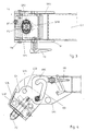
- eine bevorzugte Ausführung der Erfindung bei in oberer Halteposition befindlicher Verriegelungseinheit mit Blickrichtung parallel zur Fahrzeuglängsachse
- Fig. 2
- eine Seitenansicht zu Fig. 1 mit Blickrichtung quer zur Längsachse des Fahrzeugs
- Fig. 3
- eine Draufsicht auf Fig. 1
- Fig. 4
- die Verriegelungseinheit in einer ausgeklappten Zwischenposition
- Fig. 5
- eine Fig. 1 entsprechende Ansicht bei in unterer Halteposition befindlicher Verriegelungseinheit
- Fig. 6
- eine Seitenansicht zu Fig. 5
- Fig. 7
- die Verriegelungseinheit in einer Parkposition
- Fig. 8
- eine andere vorteilhafte Kulissenführung
- Fig. 9
- eine Kulissenführung mit Parallelverschiebung
- Fig. 10
- einen weiteren Kulissenverlauf
- Fig. 1
- a preferred embodiment of the invention with the locking unit located in the upper holding position with a viewing direction parallel to the longitudinal axis of the vehicle
- Fig. 2
- a side view of FIG. 1 looking in the direction transverse to the longitudinal axis of the vehicle
- Fig. 3
- a plan view of Fig. 1st
- Fig. 4
- the locking unit in an extended intermediate position
- Fig. 5
- a view corresponding to FIG. 1 when the locking unit is in the lower holding position
- Fig. 6
- 5 shows a side view of FIG. 5
- Fig. 7
- the locking unit in a parking position
- Fig. 8
- another advantageous backdrop
- Fig. 9
- a guided tour with parallel displacement
- Fig. 10
- another backdrop
Die in Fig. 1 bis Fig. 7 skizzierte Anordnung weist an einem Querträger QT an dessen der Mittellängsachse eines Fahrgestells abgewandtem Ende eine Trägeranordnung auf, welche im wesentlichen aus zwei vertikalen Tragplatten TP1, TP2 besteht, welche z.B. an die vertikalen Seitenflächen des als Rechteckprofil ausgebildeten Querträgers angesetzt und mit dem Querträger verschweißt sind. Die Art der Befestigung der Tragplatten an dem Querträger ist im folgenden nicht weiter von Bedeutung.The arrangement outlined in FIGS. 1 to 7 instructs QT on a cross member whose end facing away from the central longitudinal axis of a chassis is a carrier arrangement which consists essentially of two vertical support plates TP1, TP2 exists, which e.g. to the vertical side surfaces of the as a rectangular profile trained cross member and welded to the cross member are. The type of attachment of the support plates to the cross member is not of further importance below.
Die beiden Tragplatten verlaufen eben und parallel zueinander und begrenzen in Fahrtrichtung FA, d.h. in Längsrichtung des Fahrgestells einen Aufnahmeraum, innerhalb dessen eine Verriegelungseinheit verschiedene Positionen einnehmen kann. In den Tragplatten TP1, TP2 sind geformte Kulissenbahnen KB ausgebildet, in welchen ein in Fahrtrichtung verlaufender Führungsbolzen FB als Kulissenelement geführt ist. Die Tragplatten weisen horizontale Oberkanten POK auf. The two support plates run flat and parallel to each other and delimit in the direction of travel FA, i.e. a receiving space in the longitudinal direction of the chassis, within which a locking unit has different positions can take. Shaped backdrop tracks are in the support plates TP1, TP2 KB formed in which a guide bolt running in the direction of travel FB is performed as a backdrop element. The support plates have horizontal top edges POK on.
Eine der Tragplatten, vorzugsweise die in Fahrtrichtung liegende Tragplatte TP1 trägt einen Federriegel FR mit einem Sicherungsbolzen, welcher je nach Position der Verriegelungseinheit in eine von mehreren Sicherungsöffnungen eingreift.One of the support plates, preferably the support plate lying in the direction of travel TP1 carries a spring bolt FR with a safety bolt, which depends on Position of the locking unit in one of several safety openings intervenes.
Die Verriegelungseinheit besteht im bevorzugten skizzierten Beispiels aus einem Verriegelungsgehäuse, welches einen verspannbaren Verriegelungszapfen enthält. Der Verriegelungszapfen ragt mit einem am oberen Ende eines Riegelbolzens RB befindlichen, beidseitig abgeflachten pilzförmigen Kopf PZ über die obere Auflagefläche AF des Verriegelungsgehäuses hinaus und greift beim Aufsetzen eines Containers in eine nach unten weisende Öffnung eines Container-Eckbeschlags EB ein. Mittels eines Knebels KN am unteren Ende des Riegelbolzens RB kann der gesamte Zapfen um 90° gedreht werden und verriegelt so den Eckbeschlag. Mittels einer Spannmutter SPM auf einem Gewinde des Riegelbolzens kann der Verriegelungszapfen nach unten gezogen und der Containerbeschlag gegen das Verriegelungsgehäuse verspannt werden. Eine Riegelfalle RF verhindert ein unbeabsichtigtes Lösen der Spannmutter SPM. Das beschriebene Verriegelungsprinzip mittels eines verspannbaren vertikalen Verriegelungszapfens ist bekannt und gebräuchlich.In the preferred sketched example, the locking unit consists of a Locking housing, which has a lockable locking pin contains. The locking pin protrudes with one at the top of one Locking bolt RB located, flattened mushroom-shaped head PZ on both sides beyond the upper contact surface AF of the locking housing and engages when placing a container in a downward opening of a Container corner fitting EB. Using a KN knob at the lower end of the locking bolt RB, the entire pin can be turned through 90 ° and locks the corner fitting. Using a clamping nut SPM on a thread the locking pin can be pulled down and the container fitting can be clamped against the locking housing. A locking latch RF prevents the clamping nut from being unintentionally loosened SPM. The locking principle described by means of a braced vertical locking pin is known and in use.
Das Verriegelungsgehäuse umfasst in der skizzierten vorteilhaften Ausführung im wesentlichen zwei parallele vertikale Seitenplatten SP1, SP2, eine horizontale obere Auflageplatte AP, eine seitliche Stützplatte STP und eine untere Gegenplatte, an welcher sich die Spannmutter abstützt.In the advantageous embodiment outlined, the locking housing comprises essentially two parallel vertical side plates SP1, SP2, one horizontal upper support plate AP, a side support plate STP and a lower counter plate, on which the clamping nut is supported.
Die Seitenplatten SP1, SP2 verlaufen parallel zu den Tragplatten TP1, TP2 innerhalb des von diesen begrenzten Aufnahmeraums und in geringem seitlichen Abstand von diesen. Die untere Gegenplatte UP verläuft wiederum zwischen den beiden Seitenplatten SP1, SP2. Die Auflageplatte AP und die Stützplatte STP sind vorzugsweise einstückig als abgewinkelte Platte ausgeführt. Auflageplatte mit Stützplatte, Seitenplatten und Gegenplatte sind vorteilhafterweise miteinander zu dem Verriegelungsgehäuse der Verriegelungseinheit verschweißt.The side plates SP1, SP2 run parallel to the support plates TP1, TP2 within the confined space and limited to the side Distance from these. The lower counter plate UP again runs between the two side plates SP1, SP2. The support plate AP and the support plate STP are preferably made in one piece as an angled plate. Platen with support plate, side plates and counter plate are advantageous welded together to form the locking housing of the locking unit.
Der Führungsbolzen FB ist durch Bohrungen der Seitenplatten SP1, SP2 hindurchgeführt und in Längsrichtung gegen Verschiebung gesichert, beispielsweise indem der Führungsbolzen in einem zwischen die Seitenplatten eingeführten und vorzugsweise mit diesen verschweißten Lagerrohr LR verläuft und mittels eines quer durch Lagerrohr und Führungsbolzen durchgreifenden Sicherungselements gegen Verschiebung in Längsrichtung gesichert ist. Das Sicherungselement, z.B. eine Schraube SCH, ist vorzugsweise nur unter Verwendung eines Werkzeugs lösbar, so dass zwar der Sicherungsbolzen in Längsrichtung und danach die Verriegelungseinheit aus dem Aufnahmeraum entnehmbar sind, eine unbefugte Entwendung aber durch den notwendigen Werkzeugeinsatz erschwert ist. Andere Sicherungsmöglichkeiten für einen derartigen Führungsbolzen sind in verschiedener Ausführung bekannt.The guide pin FB is passed through holes in the side plates SP1, SP2 and secured in the longitudinal direction against displacement, for example by inserting the guide pin into one between the side plates and preferably runs with this welded bearing tube LR and by means of a securing element which extends through the bearing tube and guide pin is secured against displacement in the longitudinal direction. The securing element, e.g. a screw SCH, is preferably only used of a tool releasable, so that the securing bolt in the longitudinal direction and then the locking unit can be removed from the receiving space are unauthorized theft but through the necessary use of tools is difficult. Other security options for such Guide bolts are known in various designs.
Das Verriegelungsgehäuse ist um die Längsachse des Führungsbolzens FB mit diesem schwenkbar und mit dem Führungsbolzen entlang der Kulissenbahn verschiebbar. Der Führungsbolzen dient zugleich als einseitige Abstützung des Verriegelungsgehäuses gegen die Tragplatten, zumindest in der in Fig. 1 skizzierten oberen Halteposition, wo der Bolzen an einem oberen Ende KBO der Kulissenbahn einliegt und einseitig eine Gewichtsbelastung des Verriegelungsgehäuses auf die Tragplatten überträgt. Der Führungsbolzen FB ist in vertikaler Projektion nach außen gegen den Verriegelungszapfen versetzt. Das Verriegelungsgehäuse ist weiteres in der oberen Halteposition dem Führungsbolzen bezüglich des Verriegelungszapfens gegenüberliegend durch die Stützplatte STP abgestützt, welche auf dem Querträger QT aufsteht.The locking housing is around the longitudinal axis of the guide pin FB this can be pivoted and with the guide pin along the slide track displaceable. The guide pin also serves as a one-sided support of the Locking housing against the support plates, at least in the sketched in Fig. 1 upper stop position where the bolt at an upper end KBO the Slide track is inserted and a weight load on the locking housing on one side transfers to the support plates. The guide pin FB is vertical Projection outwards against the locking pin. The locking case is further in the upper holding position of the guide pin with respect to the locking pin opposite through the support plate STP supported, which stands on the cross member QT.
Das Querträgerprofil ist zum Aufnahmeraum zwischen den Tragplatten hin durch eine Winkelplatte LW verschlossen. Die Seitenplatten SP1, SP2 des Verriegelungsgehäuses liegen mit einer Gegenkante GK der Winkelplatte LP in deren oberem Bereich gering beabstandet gegenüber, wobei die Form der Gegenkanten eine horizontale oder schräge Verschiebung des Verriegelungsgehäuses aus der skizzierten Endlage des Führungsbolzens heraus verhindern, jedoch eine Verschwenkung des Verriegelungsgehäuses um die Längsachse des Führungsbolzens im Gegenuhrzeigersinn nach Lösen des Federriegels FR zulassen.The cross member profile is towards the receiving space between the support plates closed by an angle plate LW. The side plates SP1, SP2 of the locking housing lie with a counter edge GK of the angle plate LP in their upper area slightly spaced from each other, the shape of the counter edges a horizontal or oblique displacement of the locking housing prevent from the sketched end position of the guide pin, however, a pivoting of the locking housing about the longitudinal axis the guide pin counterclockwise after loosening the spring bolt FR allow.
Nach einer solchen Verschwenkung des Verriegelungsgehäuses aus der in Fig. 1 skizzierten Position im Uhrzeigersinn um ca. 90° kann das Verriegelungsgehäuse mit dem in der Kulissenbahn geführten Führungsbolzen aus dessen Endposition im oberen Ende KBO der Kulissenbahn verschoben werden, wobei die Verschiebung insbesondere anfänglich eine wesentliche horizontale Verschiebungskomponente umfasst. Die Verschiebung entlang der Kulissenbahn führt den Führungsbolzen in die untere Endposition KBU der Kulissenbahn wobei während der Verschiebung das Verriegelungsgehäuse über die seitlichen Ränder der Tragplatten hinausragt und der innerhalb des Aufnahmeraums zwischen den Tragplatten liegende Teil des Verriegelungsgehäuses, insbesondere der Seitenplatten SP1, SP2 und der Stützplatte STP leicht an der Winkelplatte vorbei geführt werden kann.After such a pivoting of the locking housing from the in Fig. 1 sketched position clockwise by approx. 90 ° can the locking housing with the guide pin guided in the sliding track from its End position in the upper end KBO of the backdrop track are moved, whereby the shift, especially initially, is an essential horizontal shift component includes. The shift along the backdrop guides the guide pin into the lower end position KBU of the slide track while moving the locking housing over the side Rims of the support plates protrude and between the inside of the receiving space part of the locking housing lying the support plates, in particular the side plates SP1, SP2 and the support plate STP slightly on the angle plate can be passed.
In der Position des Führungsbolzens am unteren Ende KBU der Kulissenbahn wird das Verriegelungsgehäuse im Uhrzeigersinn zurückgeschwenkt in die in Fig. 5 und Fig. 6 skizzierte untere Halteposition, wobei die Gegenkanten der Seitenplatten SP1, SP2 in geringem Abstand der unteren Kante der Winkelplatte LW gegenüberstehen und hierdurch eine horizontale Verschiebung des Verriegelungsgehäuses zur Mittellängsebene des Fahrzeugs hin verhindern. Eine horizontale Verschiebung in entgegengesetzter Richtung ist hier wie auch in der oberen Halteposition durch das Einliegen des Führunsgbolzens im Ende der Kulissenbahn verhindert. Zusätzlich kann der Überstand der Winkelplatte LW über die Oberkante des Querträgers QT in der oberen bzw. ein auf die Winkelplatte aufgeschweißter Vierkantstab eine Sicherung gegen seitliche Verschiebung bieten. Eine vertikale Verschiebung des Verriegelungsgehäuses ohne Verschwenkung ist durch den zumindest annähernd horizontalen Verlauf der Kulissenbahn im Bereich ihres unteren Endes verhindert. Eine Verschwenkung ist bei verspanntem Verriegelungszapfen nicht möglich.In the position of the guide pin at the lower end KBU of the slide track the locking housing is swiveled clockwise back into the in Fig. 5 and Fig. 6 outlined lower holding position, the opposite edges of the Side plates SP1, SP2 a short distance from the lower edge of the angle plate LW face and thereby a horizontal displacement of the Prevent the locking housing from moving towards the median longitudinal plane of the vehicle. A horizontal shift in the opposite direction is here as well in the upper holding position by inserting the guide pin in the end the backdrop track prevented. In addition, the protrusion of the angle plate LW over the upper edge of the cross member QT in the upper or one on the Angle plate welded square bar to secure against lateral displacement Offer. A vertical displacement of the locking housing without Swiveling is due to the at least approximately horizontal course of the Slide track prevented in the area of its lower end. A swivel is not possible if the locking pin is tensioned.
Die Stützplatte STP taucht bei der Verschiebung und Verschwenkung der Verriegelungseinheit in die untere Halteposition zwischen die Tragplatten TP1, TP2 ein. Eine Abstützung des Verriegelungsgehäuses gegen vertikale Belastung erfolgt in der in Fig. 5 und Fig. 6 skizzierten Position vorzugsweise in der Form, dass die obere Auflageplatte AP unmittelbar auf den horizontalen oberen Plattenkanten POK der Tragplatten TP1, TP2 aufliegt.The support plate STP dips when the locking unit is moved and swiveled in the lower holding position between the support plates TP1, TP2 on. A support for the locking housing against vertical loads in the position outlined in FIGS. 5 and 6 preferably takes the form that the upper platen AP directly on the horizontal upper plate edges POK of the support plates TP1, TP2 rests.
Eine Sicherung der Position der Verriegelungseinheit in der oberen und der unteren Halteposition mittels des in Sicherungsöffnungen SOO bzw. SOU der Seitenplatte SP1 eingreifenden Federriegels ist insbesondere für den unbelasteten Zustand des Verriegelungsgehäuses von Bedeutung.Securing the position of the locking unit in the top and the lower holding position by means of the SOO or SOU in the safety openings Side plate SP1 engaging spring bolt is especially for the unloaded Condition of the locking housing is important.
Gemäß einer besonders vorteilhaften Weiterbildung der in Fig. 1 bis Fig. 6 skizzierten Verriegelungsanordnung kann vorgesehen sein, die Verriegelungseinheit aus der in Fig. 4 skizzierten ausgeschwenkten Position nicht im Uhrzeigersinn in eine Halteposition sondern im Gegenuhrzeigersinn weiter in eine in Fig. 7 skizzierte Parkposition zu verschwenken und z.B. durch einen weiteren Federriegel FR2 in dieser zu sichern. Durch Verschwenken in die Parkposition entfällt der Überstand des Verriegelungszapfens über die Oberkanten der Tragplatten und die Verriegelungsanordnung kann auch für die Abstützung kürzerer Container an Zwischenpositionen in Längsrichtung der Fahrstelle eingesetzt und beim Transport längerer Behälter mit tiefliegendem Containerboden weggeklappt werden.According to a particularly advantageous development of the one outlined in FIGS. 1 to 6 Locking arrangement can be provided, the locking unit from the swiveled-out position sketched in FIG. 4, not clockwise into a holding position but counterclockwise further into one in Fig. 7 outlined parking position and e.g. by another spring bolt Secure FR2 in this. By swiveling into the parking position the protrusion of the locking pin over the upper edges of the Carrier plates and the locking arrangement can also be shorter for support Containers used at intermediate positions in the longitudinal direction of the driving position and when transporting longer containers with deep container bottoms be folded away.
In Fig. 8 ist eine Kulissenbahn KB8 skizziert, bei welcher der Abschnitt zum oberen Ende KBO8 der Kulissenbahn im wesentlichen horizontal verläuft. Hierdurch kann eine klarere Festlegung des Verriegelungsgehäuses gegen abhebend wirkende Kräfte erzielt werden. Demgegenüber weist die in dem Beispiel nach Fig. 1 bis Fig. 7 gewählte Kulissenführung mit einem zum oberen Ende KBO der Kulissenbahn im letzten Abschnitt fallenden Verlauf den Vorteil auf, dass bei der typischen Belastung der Anordnung mit dem Gewicht des Containers der Führungsbolzen auch in horizontaler Richtung in eine eindeutige stabile Endposition gedrückt wird.In Fig. 8 a backdrop track KB8 is outlined, in which the section to the upper end KBO8 of the slide is essentially horizontal. hereby can be a clearer definition of the locking case against lifting acting forces can be achieved. In contrast, the in the example according to Fig. 1 to Fig. 7 selected guide with one to the upper end KBO the backdrop in the last section, the advantage of that with the typical loading of the assembly with the weight of the container the guide pin also in the horizontal direction in a clearly stable End position is pressed.
Bei der in Fig. 9 skizzierten Anordnung ist das Verriegelungsgehäuse mit zwei Führungsbolzen FB1, FB2 in einer Kulisse KB9 parallel geführt, wobei wiederum der Verschiebung zwischen einer oberen und einer unteren Halteposition (gezeigt ist die untere Halteposition) eine horizontale Wegkomponente umfasst. Die Einfügung einer horizontalen Wegkomponente bei der Verschiebung zwischen einer oberen und einer unteren Halteposition ermöglicht allgemein, wie die skizzierten Beispiele veranschaulichen, dass die vertikale Unterstützung des Führungsbolzens oder eines anderen Lagerelements in der oberen Halteposition trotz der exakt vertikal darunterliegenden Position dieses Lagerelements in der unteren Halteposition ortsfest in der Trägeranordnung und damit einfach und stabil ausgeführt sein kann. In the arrangement outlined in FIG. 9, the locking housing has two Guide bolts FB1, FB2 are guided in parallel in a link KB9, whereby again the shift between an upper and a lower stop position (the lower stop position is shown) comprises a horizontal path component. The insertion of a horizontal path component when moving between an upper and a lower stop position generally allows how The examples outlined illustrate that vertical support the guide pin or another bearing element in the upper holding position despite the exactly vertical position of this bearing element in the lower holding position stationary in the carrier arrangement and thus can be simple and stable.
Die Kulissenanordnung bietet mit der unkomplizierten Führung der Verriegelungseinheit bei der Verschiebung, der einfachen Sicherung gegen Verlieren oder Entwenden, den definierten Endpositionen, der Realisierbarkeit als Ausschnitt in einer ebenen Platte und dem gleichzeitig geringen Verbrauch an Plattenfläche und damit geringer Beeinträchtigung der Tragfähigkeit der Tragplatten besondere Vorteile.The setting arrangement offers with the uncomplicated guidance of the locking unit with the shift, the simple safeguard against losing or stealing, the defined end positions, the feasibility as a detail in a flat plate and at the same time low consumption Plate area and thus little impairment of the load-bearing capacity of the support plates special advantages.
Die Verriegelungseinheit wird für die Verschiebung zwischen der oberen und der unteren Halteposition vorzugsweise vom Querträger QT weg nach außen verlagert, wofür im Beispiel nach Fig. 9 die Kulissenbahn zwischen den Endpositionen gegenüber diesen vom Querträger weg versetzt ist. In den Ausführungen nach Fig. 1 bis Fig. 8 wird die Verriegelungseinheit durch die Verschwenkung nach außen verlagert. Die Endpositionen der Kulissenbahnen liegen hier gegenüber dem übrigen Verlauf der Kulissenbahnen außen, so dass einerseits eine breite Basis der Abstützung zwischen Führungsbolzen und Stützplattenabschnitt in der oberen Halteposition gegeben ist und zum anderen die seitliche Erstreckung der Tragplatten gering gehalten werden kann.The locking unit is used for the shift between the top and the lower holding position preferably away from the cross member QT 9, for which purpose the slide track between the end positions in the example according to FIG. 9 is offset from the cross member. In the versions according to Fig. 1 to Fig. 8, the locking unit by pivoting shifted to the outside. The end positions of the backdrop tracks are here compared to the rest of the course tracks outside, so that on the one hand a wide base of support between the guide pin and the support plate section is given in the upper holding position and secondly the lateral one Extension of the support plates can be kept low.
Die Fig. 10 zeigt eine weitere Variante, bei welcher in Abwandlung der Ausführungen nach Fig. 1 bis Fig. 8 die Bolzenenden des Führungsbolzen einseitig abgeflacht sind und lediglich Halbrundstababschnitte FBH bilden und die Endpositionen der Kulissenbahn KBH an die Bolzenenden angepaßte Viertelkreisaussparungen bilden, in welchen die Bolzenenden gegen lineare Verschiebungen in alle Richtungen gesichert sind. Ein Lösen aus dieser gesicherten Position erfolgt durch Verschwenken der mit den Bolzen verbundenen Verriegelungseinheit um die Bolzenlängsachse, worauf die Bolzenenden in einem vertikalen Kulissenabschnitt zwischen den Endpositionen verschiebbar sind und durch Zurückschwenken der Verriegelungseinheit in die Endpositionen einrükken. In diesem Beispiel tritt keine horizontale Bewegungskomponente des gesamten Bolzens bei der Verschiebung zwischen den Endpositionen auf, sondern lediglich eine Verschwenkung und eine vertikale Verschiebung. Der vertikale Verlauf der Kulissenbahn ist wiederum von nachrangiger Bedeutung. Eine Lagesicherung durch abgeflachte Bolzenenden ist auch für andere Kulissenbahnführungen denkbar.10 shows a further variant, in which a modification of the designs 1 to 8, the bolt ends of the guide bolt on one side are flattened and only form semicircular rod sections FBH and the end positions quarter-round recesses adapted to the KBH slide form in which the bolt ends against linear displacements are secured in all directions. A release from this secured position is done by pivoting the locking unit connected to the bolt around the bolt longitudinal axis, whereupon the bolt ends in a vertical Link section between the end positions are displaceable and by swiveling the locking unit back into the end positions. In this example, there is no horizontal motion component of the whole Bolts when moving between the end positions, but instead just a swivel and a vertical shift. The vertical The course of the backdrop track is again of secondary importance. A Securing the position with flattened bolt ends is also possible for other slide tracks conceivable.
Die vorstehend und die in den Ansprüchen angegebenen sowie die den Abbildungen entnehmbaren Merkmale sind sowohl einzeln als auch in verschiedener Kombination vorteilhaft realisierbar. Die Erfindung ist nicht auf die beschriebenen Ausführungsbeispiele beschränkt, sondern im Rahmen fachmännischen Könnens in mancherlei Weise abwandelbar. Insbesondere können die Kulissenbahn auch in der Verriegelungseinheit ausgebildet und darin geführte Kulissenelemente an der Trägeranordnung befestigt sein.The above and those specified in the claims as well as those in the illustrations Removable features are both individually and in different Combination can be advantageously implemented. The invention is not based on those described Embodiments limited, but within the scope of experts Can be modified in many ways. In particular, the backdrop also formed in the locking unit and guide elements guided therein be attached to the support assembly.
Claims (13)
Priority Applications (1)
| Application Number | Priority Date | Filing Date | Title |
|---|---|---|---|
| DE10312595A DE10312595B4 (en) | 2001-10-02 | 2003-03-21 | Locking arrangement for mounting containers on a chassis and chassis with such locking arrangements |
Applications Claiming Priority (2)
| Application Number | Priority Date | Filing Date | Title |
|---|---|---|---|
| DE10148728A DE10148728C1 (en) | 2001-10-02 | 2001-10-02 | Locking arrangement for containers |
| DE10148728 | 2001-10-02 |
Publications (3)
| Publication Number | Publication Date |
|---|---|
| EP1300284A2 true EP1300284A2 (en) | 2003-04-09 |
| EP1300284A3 EP1300284A3 (en) | 2006-06-21 |
| EP1300284B1 EP1300284B1 (en) | 2007-10-24 |
Family
ID=7701209
Family Applications (1)
| Application Number | Title | Priority Date | Filing Date |
|---|---|---|---|
| EP02021414A Expired - Lifetime EP1300284B1 (en) | 2001-10-02 | 2002-09-25 | Container locking arrangement |
Country Status (4)
| Country | Link |
|---|---|
| EP (1) | EP1300284B1 (en) |
| AT (1) | ATE376503T1 (en) |
| DE (4) | DE10148728C1 (en) |
| ES (1) | ES2292669T3 (en) |
Cited By (2)
| Publication number | Priority date | Publication date | Assignee | Title |
|---|---|---|---|---|
| EP1621399A1 (en) * | 2004-07-28 | 2006-02-01 | Holger Stuht | Device for locking containers on a vehicle frame at different heights |
| EP3222464A1 (en) * | 2016-03-24 | 2017-09-27 | Sonntag transport technology GmbH & Co. KG | Frame system for motor vehicle structures |
Families Citing this family (6)
| Publication number | Priority date | Publication date | Assignee | Title |
|---|---|---|---|---|
| DE102004033886B4 (en) * | 2004-07-13 | 2009-04-09 | Schneider Fahrzeug- Und Containertechnik Gmbh | Holding arrangement for containers |
| RU178819U9 (en) * | 2017-08-29 | 2020-03-03 | РЕЙЛ 1520 АйПи ЛТД | CONTAINER FASTENING DEVICE |
| RU2764316C1 (en) * | 2021-07-14 | 2022-01-17 | Общество с ограниченной ответственностью "СотекКомЦентр", ООО "СКЦ" | Apparatus for securing containers on a platform |
| RU2763618C1 (en) * | 2021-07-16 | 2021-12-30 | Общество с ограниченной ответственностью "СотекКомЦентр", ООО "СКЦ" | Device for fixing containers on the platform |
| RU209816U1 (en) * | 2021-12-02 | 2022-03-23 | Общество С Ограниченной Ответственностью "Рейл1520 Ай Пи" (Ооо "Рейл1520 Ай Пи") | DEVICE FOR FIXING LOADS ON VEHICLE |
| DE102022105423A1 (en) * | 2022-03-08 | 2023-09-14 | Hamburger Patent Schmiede Gmbh | Raising and lowering arrangement for container locking and raising and lowering methods therewith |
Citations (7)
| Publication number | Priority date | Publication date | Assignee | Title |
|---|---|---|---|---|
| DE1938915A1 (en) | 1968-08-06 | 1970-02-12 | Ibm | Magnetic thin-film storage |
| DE1966501A1 (en) | 1968-06-15 | 1972-11-16 | Elkins Gordon Charles | Connection body for a device for aligning and locking transport containers on vehicles |
| EP0337011A1 (en) | 1988-04-13 | 1989-10-18 | Hfr - Rodekro A/S | Carrying device with locking elements for mounting and fixing interchangeable bodies on a vehicle frame |
| DE29616083U1 (en) | 1996-09-16 | 1996-12-05 | Fahrzeugwerk Luebtheen Gmbh | Height-adjustable locking device for swap bodies |
| DE29622249U1 (en) | 1995-12-13 | 1997-02-20 | Pineiro Bouza Manuel | Anchoring for containers with multiple positioning |
| DE19538915A1 (en) | 1995-10-19 | 1997-04-24 | Jost Werke Ag | Holding device for container locking device |
| DE19755638C2 (en) | 1997-12-15 | 1999-10-07 | Jost Werke Ag | Holding device for a container locking device that can be locked at two heights |
Family Cites Families (5)
| Publication number | Priority date | Publication date | Assignee | Title |
|---|---|---|---|---|
| US3507226A (en) * | 1968-01-22 | 1970-04-21 | Illinois Railway Equipment Co | Device for locking a container in position on a floor of a flat car |
| US3717372A (en) * | 1970-12-15 | 1973-02-20 | Pullman Inc | Container hold-down locking means |
| DE7136868U (en) * | 1971-09-29 | 1972-01-13 | Conver Ingenieur-Technik Gmbh & Co Kg | Device for releasable locking of containers on chassis or the like |
| US4026596A (en) * | 1975-06-05 | 1977-05-31 | Pullman Incorporated | Container hold down locking means |
| DE2927231A1 (en) * | 1979-07-05 | 1981-02-19 | Graaff Kg | DEVICE FOR LOCKING STANDING PALLETS |
-
2001
- 2001-10-02 DE DE10148728A patent/DE10148728C1/en not_active Expired - Fee Related
-
2002
- 2002-09-25 DE DE50211107T patent/DE50211107D1/en not_active Expired - Lifetime
- 2002-09-25 AT AT02021414T patent/ATE376503T1/en active
- 2002-09-25 ES ES02021414T patent/ES2292669T3/en not_active Expired - Lifetime
- 2002-09-25 EP EP02021414A patent/EP1300284B1/en not_active Expired - Lifetime
-
2003
- 2003-03-21 DE DE10312596A patent/DE10312596A1/en not_active Withdrawn
- 2003-03-21 DE DE10312595A patent/DE10312595B4/en not_active Expired - Lifetime
Patent Citations (7)
| Publication number | Priority date | Publication date | Assignee | Title |
|---|---|---|---|---|
| DE1966501A1 (en) | 1968-06-15 | 1972-11-16 | Elkins Gordon Charles | Connection body for a device for aligning and locking transport containers on vehicles |
| DE1938915A1 (en) | 1968-08-06 | 1970-02-12 | Ibm | Magnetic thin-film storage |
| EP0337011A1 (en) | 1988-04-13 | 1989-10-18 | Hfr - Rodekro A/S | Carrying device with locking elements for mounting and fixing interchangeable bodies on a vehicle frame |
| DE19538915A1 (en) | 1995-10-19 | 1997-04-24 | Jost Werke Ag | Holding device for container locking device |
| DE29622249U1 (en) | 1995-12-13 | 1997-02-20 | Pineiro Bouza Manuel | Anchoring for containers with multiple positioning |
| DE29616083U1 (en) | 1996-09-16 | 1996-12-05 | Fahrzeugwerk Luebtheen Gmbh | Height-adjustable locking device for swap bodies |
| DE19755638C2 (en) | 1997-12-15 | 1999-10-07 | Jost Werke Ag | Holding device for a container locking device that can be locked at two heights |
Cited By (3)
| Publication number | Priority date | Publication date | Assignee | Title |
|---|---|---|---|---|
| EP1621399A1 (en) * | 2004-07-28 | 2006-02-01 | Holger Stuht | Device for locking containers on a vehicle frame at different heights |
| EP3222464A1 (en) * | 2016-03-24 | 2017-09-27 | Sonntag transport technology GmbH & Co. KG | Frame system for motor vehicle structures |
| DE102016204985B4 (en) | 2016-03-24 | 2019-05-23 | Sonntag transport technology GmbH & Co. KG | Frame system for bodywork of motor vehicles |
Also Published As
| Publication number | Publication date |
|---|---|
| DE50211107D1 (en) | 2007-12-06 |
| ATE376503T1 (en) | 2007-11-15 |
| EP1300284A3 (en) | 2006-06-21 |
| DE10312596A1 (en) | 2004-09-30 |
| ES2292669T3 (en) | 2008-03-16 |
| DE10312595A1 (en) | 2004-09-30 |
| DE10312595B4 (en) | 2010-12-09 |
| DE10148728C1 (en) | 2003-05-15 |
| EP1300284B1 (en) | 2007-10-24 |
Similar Documents
| Publication | Publication Date | Title |
|---|---|---|
| DE4305190B4 (en) | Reach truck | |
| EP0923495B1 (en) | Set of parts for rigidly interconnecting the corners of two containers provided with hollow corner fittings, tool therefore and container | |
| EP0101054B1 (en) | Luggage carrier for vehicles, especially for caravans | |
| EP0583295A1 (en) | Quick-release fastening device. | |
| EP1522455B1 (en) | Device for securing loads in transportation units | |
| EP1700745B1 (en) | Load carrier, particularly a bicycle carrier | |
| EP1300284B1 (en) | Container locking arrangement | |
| EP0939005A1 (en) | Device for the fixing of articles in the luggage compartment of a motor vehicle | |
| DE3834360A1 (en) | MOTOR VEHICLE ROOF RACK | |
| EP1900572B1 (en) | Device for adjusting the vertical position of a container locking device | |
| DE102006049557A1 (en) | Locking element for safety of tilting pin, has console bracket fixed at lock holding part and locking head connected by spring arrangement | |
| EP0334387B1 (en) | Fixing device for a detachable stanchion for a goods transportation vehicle | |
| DE10047093A1 (en) | Device to lock container to vehicle chassis has first locking element positioned at larger distance to its carrier when in rest position | |
| DE1936779C3 (en) | Container fastening device | |
| EP0545019A1 (en) | Device for latching a container on a vehicle frame | |
| DE7807246U1 (en) | Tool trolleys, especially for repair shops or the like | |
| EP0481114A1 (en) | Unlockable tipping bearing of the dumping body of a three-way tipper | |
| DE60034242T2 (en) | ARRANGEMENT IN A LOAD CARRIER | |
| DE10232561A1 (en) | Arrangement for holding different types of containers on a chassis | |
| EP0115010A1 (en) | Device for fitting delivery vans with furniture (estate cars, minibuses) | |
| DE60132712T2 (en) | DEVICE FOR FIXING A STREBE IN A STRIPE MUFFLE | |
| DE202022100256U1 (en) | Load securing beams for securing means of transport of loads | |
| EP0556541B1 (en) | Coupling device | |
| EP3960595A1 (en) | Trailer | |
| DE3300459A1 (en) | Device for lashing containers or the like on board ships |
Legal Events
| Date | Code | Title | Description |
|---|---|---|---|
| PUAI | Public reference made under article 153(3) epc to a published international application that has entered the european phase |
Free format text: ORIGINAL CODE: 0009012 |
|
| AK | Designated contracting states |
Designated state(s): AT BE BG CH CY CZ DE DK EE ES FI FR GB GR IE IT LI LU MC NL PT SE SK TR Kind code of ref document: A2 Designated state(s): AT BE BG CH CY CZ DE DK EE ES FI FR GB GR IE IT LI LU MC NL PT SE SK TR |
|
| AX | Request for extension of the european patent |
Extension state: AL LT LV MK RO SI |
|
| PUAL | Search report despatched |
Free format text: ORIGINAL CODE: 0009013 |
|
| AK | Designated contracting states |
Kind code of ref document: A3 Designated state(s): AT BE BG CH CY CZ DE DK EE ES FI FR GB GR IE IT LI LU MC NL PT SE SK TR |
|
| AX | Request for extension of the european patent |
Extension state: AL LT LV MK RO SI |
|
| 17P | Request for examination filed |
Effective date: 20061221 |
|
| AKX | Designation fees paid |
Designated state(s): AT BE BG CH CY CZ DE DK EE ES FI FR GB GR IE IT LI LU MC NL PT SE SK TR |
|
| 17Q | First examination report despatched |
Effective date: 20070219 |
|
| GRAP | Despatch of communication of intention to grant a patent |
Free format text: ORIGINAL CODE: EPIDOSNIGR1 |
|
| GRAS | Grant fee paid |
Free format text: ORIGINAL CODE: EPIDOSNIGR3 |
|
| GRAA | (expected) grant |
Free format text: ORIGINAL CODE: 0009210 |
|
| AK | Designated contracting states |
Kind code of ref document: B1 Designated state(s): AT BE BG CH CY CZ DE DK EE ES FI FR GB GR IE IT LI LU MC NL PT SE SK TR |
|
| REG | Reference to a national code |
Ref country code: GB Ref legal event code: FG4D Free format text: NOT ENGLISH |
|
| RTI1 | Title (correction) |
Free format text: CONTAINER LOCKING ARRANGEMENT |
|
| REG | Reference to a national code |
Ref country code: CH Ref legal event code: EP |
|
| REG | Reference to a national code |
Ref country code: IE Ref legal event code: FG4D Free format text: LANGUAGE OF EP DOCUMENT: GERMAN |
|
| REF | Corresponds to: |
Ref document number: 50211107 Country of ref document: DE Date of ref document: 20071206 Kind code of ref document: P |
|
| REG | Reference to a national code |
Ref country code: GR Ref legal event code: EP Ref document number: 20080400231 Country of ref document: GR |
|
| REG | Reference to a national code |
Ref country code: ES Ref legal event code: FG2A Ref document number: 2292669 Country of ref document: ES Kind code of ref document: T3 |
|
| ET | Fr: translation filed | ||
| PG25 | Lapsed in a contracting state [announced via postgrant information from national office to epo] |
Ref country code: SE Free format text: LAPSE BECAUSE OF FAILURE TO SUBMIT A TRANSLATION OF THE DESCRIPTION OR TO PAY THE FEE WITHIN THE PRESCRIBED TIME-LIMIT Effective date: 20080124 |
|
| GBV | Gb: ep patent (uk) treated as always having been void in accordance with gb section 77(7)/1977 [no translation filed] | ||
| PG25 | Lapsed in a contracting state [announced via postgrant information from national office to epo] |
Ref country code: PT Free format text: LAPSE BECAUSE OF FAILURE TO SUBMIT A TRANSLATION OF THE DESCRIPTION OR TO PAY THE FEE WITHIN THE PRESCRIBED TIME-LIMIT Effective date: 20080324 |
|
| REG | Reference to a national code |
Ref country code: IE Ref legal event code: FD4D |
|
| PG25 | Lapsed in a contracting state [announced via postgrant information from national office to epo] |
Ref country code: DK Free format text: LAPSE BECAUSE OF FAILURE TO SUBMIT A TRANSLATION OF THE DESCRIPTION OR TO PAY THE FEE WITHIN THE PRESCRIBED TIME-LIMIT Effective date: 20071024 |
|
| PLBE | No opposition filed within time limit |
Free format text: ORIGINAL CODE: 0009261 |
|
| STAA | Information on the status of an ep patent application or granted ep patent |
Free format text: STATUS: NO OPPOSITION FILED WITHIN TIME LIMIT |
|
| 26N | No opposition filed |
Effective date: 20080725 |
|
| PG25 | Lapsed in a contracting state [announced via postgrant information from national office to epo] |
Ref country code: IE Free format text: LAPSE BECAUSE OF FAILURE TO SUBMIT A TRANSLATION OF THE DESCRIPTION OR TO PAY THE FEE WITHIN THE PRESCRIBED TIME-LIMIT Effective date: 20071024 |
|
| PG25 | Lapsed in a contracting state [announced via postgrant information from national office to epo] |
Ref country code: GB Free format text: LAPSE BECAUSE OF FAILURE TO SUBMIT A TRANSLATION OF THE DESCRIPTION OR TO PAY THE FEE WITHIN THE PRESCRIBED TIME-LIMIT Effective date: 20071024 |
|
| PG25 | Lapsed in a contracting state [announced via postgrant information from national office to epo] |
Ref country code: FI Free format text: LAPSE BECAUSE OF FAILURE TO SUBMIT A TRANSLATION OF THE DESCRIPTION OR TO PAY THE FEE WITHIN THE PRESCRIBED TIME-LIMIT Effective date: 20071024 |
|
| PG25 | Lapsed in a contracting state [announced via postgrant information from national office to epo] |
Ref country code: MC Free format text: LAPSE BECAUSE OF NON-PAYMENT OF DUE FEES Effective date: 20080930 Ref country code: EE Free format text: LAPSE BECAUSE OF FAILURE TO SUBMIT A TRANSLATION OF THE DESCRIPTION OR TO PAY THE FEE WITHIN THE PRESCRIBED TIME-LIMIT Effective date: 20071024 |
|
| REG | Reference to a national code |
Ref country code: CH Ref legal event code: PL |
|
| PG25 | Lapsed in a contracting state [announced via postgrant information from national office to epo] |
Ref country code: CY Free format text: LAPSE BECAUSE OF FAILURE TO SUBMIT A TRANSLATION OF THE DESCRIPTION OR TO PAY THE FEE WITHIN THE PRESCRIBED TIME-LIMIT Effective date: 20071024 |
|
| PG25 | Lapsed in a contracting state [announced via postgrant information from national office to epo] |
Ref country code: CH Free format text: LAPSE BECAUSE OF NON-PAYMENT OF DUE FEES Effective date: 20080930 Ref country code: LI Free format text: LAPSE BECAUSE OF NON-PAYMENT OF DUE FEES Effective date: 20080930 |
|
| PG25 | Lapsed in a contracting state [announced via postgrant information from national office to epo] |
Ref country code: TR Free format text: LAPSE BECAUSE OF FAILURE TO SUBMIT A TRANSLATION OF THE DESCRIPTION OR TO PAY THE FEE WITHIN THE PRESCRIBED TIME-LIMIT Effective date: 20071024 |
|
| REG | Reference to a national code |
Ref country code: DE Ref legal event code: R082 Ref document number: 50211107 Country of ref document: DE Representative=s name: GERHARD WEBER, DE |
|
| REG | Reference to a national code |
Ref country code: DE Ref legal event code: R082 Ref document number: 50211107 Country of ref document: DE Representative=s name: BAUR & WEBER PATENTANWAELTE PARTG MBB, DE Effective date: 20120402 Ref country code: DE Ref legal event code: R081 Ref document number: 50211107 Country of ref document: DE Owner name: SCHMITZ CARGOBULL GOTHA GMBH, DE Free format text: FORMER OWNER: SCHMITZ GOTHA FAHRZEUGWERKE GMBH, 99867 GOTHA, DE Effective date: 20120402 Ref country code: DE Ref legal event code: R082 Ref document number: 50211107 Country of ref document: DE Representative=s name: BAUR & WEBER PATENTANWAELTE, DE Effective date: 20120402 |
|
| REG | Reference to a national code |
Ref country code: DE Ref legal event code: R082 Ref document number: 50211107 Country of ref document: DE Representative=s name: BAUR & WEBER PATENTANWAELTE PARTG MBB, DE Ref country code: DE Ref legal event code: R082 Ref document number: 50211107 Country of ref document: DE Representative=s name: BAUR & WEBER PATENTANWAELTE, DE |
|
| REG | Reference to a national code |
Ref country code: FR Ref legal event code: PLFP Year of fee payment: 14 |
|
| PGFP | Annual fee paid to national office [announced via postgrant information from national office to epo] |
Ref country code: SK Payment date: 20150918 Year of fee payment: 14 Ref country code: ES Payment date: 20150923 Year of fee payment: 14 Ref country code: CZ Payment date: 20150918 Year of fee payment: 14 Ref country code: BG Payment date: 20150923 Year of fee payment: 14 Ref country code: LU Payment date: 20150922 Year of fee payment: 14 |
|
| PGFP | Annual fee paid to national office [announced via postgrant information from national office to epo] |
Ref country code: FR Payment date: 20150923 Year of fee payment: 14 Ref country code: GR Payment date: 20150921 Year of fee payment: 14 Ref country code: AT Payment date: 20150921 Year of fee payment: 14 |
|
| PGFP | Annual fee paid to national office [announced via postgrant information from national office to epo] |
Ref country code: IT Payment date: 20150925 Year of fee payment: 14 |
|
| REG | Reference to a national code |
Ref country code: AT Ref legal event code: MM01 Ref document number: 376503 Country of ref document: AT Kind code of ref document: T Effective date: 20160925 |
|
| PG25 | Lapsed in a contracting state [announced via postgrant information from national office to epo] |
Ref country code: CZ Free format text: LAPSE BECAUSE OF NON-PAYMENT OF DUE FEES Effective date: 20160925 |
|
| REG | Reference to a national code |
Ref country code: SK Ref legal event code: MM4A Ref document number: E 3033 Country of ref document: SK Effective date: 20160925 |
|
| REG | Reference to a national code |
Ref country code: FR Ref legal event code: ST Effective date: 20170531 |
|
| REG | Reference to a national code |
Ref country code: GR Ref legal event code: ML Ref document number: 20080400231 Country of ref document: GR Effective date: 20170411 |
|
| PG25 | Lapsed in a contracting state [announced via postgrant information from national office to epo] |
Ref country code: GR Free format text: LAPSE BECAUSE OF NON-PAYMENT OF DUE FEES Effective date: 20170411 Ref country code: SK Free format text: LAPSE BECAUSE OF NON-PAYMENT OF DUE FEES Effective date: 20160925 Ref country code: FR Free format text: LAPSE BECAUSE OF NON-PAYMENT OF DUE FEES Effective date: 20160930 |
|
| PG25 | Lapsed in a contracting state [announced via postgrant information from national office to epo] |
Ref country code: AT Free format text: LAPSE BECAUSE OF NON-PAYMENT OF DUE FEES Effective date: 20160925 Ref country code: IT Free format text: LAPSE BECAUSE OF NON-PAYMENT OF DUE FEES Effective date: 20160925 Ref country code: LU Free format text: LAPSE BECAUSE OF NON-PAYMENT OF DUE FEES Effective date: 20160925 Ref country code: BG Free format text: LAPSE BECAUSE OF NON-PAYMENT OF DUE FEES Effective date: 20170406 |
|
| PGFP | Annual fee paid to national office [announced via postgrant information from national office to epo] |
Ref country code: BE Payment date: 20170925 Year of fee payment: 16 Ref country code: NL Payment date: 20170925 Year of fee payment: 16 |
|
| PG25 | Lapsed in a contracting state [announced via postgrant information from national office to epo] |
Ref country code: ES Free format text: LAPSE BECAUSE OF NON-PAYMENT OF DUE FEES Effective date: 20160926 |
|
| REG | Reference to a national code |
Ref country code: ES Ref legal event code: FD2A Effective date: 20181123 |
|
| REG | Reference to a national code |
Ref country code: NL Ref legal event code: MM Effective date: 20181001 |
|
| REG | Reference to a national code |
Ref country code: BE Ref legal event code: MM Effective date: 20180930 |
|
| PG25 | Lapsed in a contracting state [announced via postgrant information from national office to epo] |
Ref country code: NL Free format text: LAPSE BECAUSE OF NON-PAYMENT OF DUE FEES Effective date: 20181001 |
|
| PG25 | Lapsed in a contracting state [announced via postgrant information from national office to epo] |
Ref country code: BE Free format text: LAPSE BECAUSE OF NON-PAYMENT OF DUE FEES Effective date: 20180930 |
|
| PGFP | Annual fee paid to national office [announced via postgrant information from national office to epo] |
Ref country code: DE Payment date: 20210930 Year of fee payment: 20 |
|
| REG | Reference to a national code |
Ref country code: DE Ref legal event code: R071 Ref document number: 50211107 Country of ref document: DE |