EP1300264A2 - Luftfeder für eine Fahrzeugachsaufhängung - Google Patents
Luftfeder für eine Fahrzeugachsaufhängung Download PDFInfo
- Publication number
- EP1300264A2 EP1300264A2 EP02022068A EP02022068A EP1300264A2 EP 1300264 A2 EP1300264 A2 EP 1300264A2 EP 02022068 A EP02022068 A EP 02022068A EP 02022068 A EP02022068 A EP 02022068A EP 1300264 A2 EP1300264 A2 EP 1300264A2
- Authority
- EP
- European Patent Office
- Prior art keywords
- plunger
- air spring
- individual parts
- spring according
- support body
- Prior art date
- Legal status (The legal status is an assumption and is not a legal conclusion. Google has not performed a legal analysis and makes no representation as to the accuracy of the status listed.)
- Granted
Links
- 239000000725 suspension Substances 0.000 title claims abstract description 5
- 239000002184 metal Substances 0.000 claims abstract description 3
- 238000007654 immersion Methods 0.000 claims description 4
- 238000005096 rolling process Methods 0.000 claims description 4
- 239000004033 plastic Substances 0.000 claims description 3
- 229920003023 plastic Polymers 0.000 claims description 3
- 239000011152 fibreglass Substances 0.000 claims description 2
- 230000037431 insertion Effects 0.000 abstract 1
- 238000003780 insertion Methods 0.000 abstract 1
- 239000002131 composite material Substances 0.000 description 3
- 238000010276 construction Methods 0.000 description 2
- 230000006835 compression Effects 0.000 description 1
- 238000007906 compression Methods 0.000 description 1
- 230000007797 corrosion Effects 0.000 description 1
- 238000005260 corrosion Methods 0.000 description 1
- 238000010586 diagram Methods 0.000 description 1
- 238000002347 injection Methods 0.000 description 1
- 239000007924 injection Substances 0.000 description 1
- 239000000243 solution Substances 0.000 description 1
Images

Classifications
-
- B—PERFORMING OPERATIONS; TRANSPORTING
- B60—VEHICLES IN GENERAL
- B60G—VEHICLE SUSPENSION ARRANGEMENTS
- B60G11/00—Resilient suspensions characterised by arrangement, location or kind of springs
- B60G11/26—Resilient suspensions characterised by arrangement, location or kind of springs having fluid springs only, e.g. hydropneumatic springs
- B60G11/28—Resilient suspensions characterised by arrangement, location or kind of springs having fluid springs only, e.g. hydropneumatic springs characterised by means specially adapted for attaching the spring to axle or sprung part of the vehicle
-
- F—MECHANICAL ENGINEERING; LIGHTING; HEATING; WEAPONS; BLASTING
- F16—ENGINEERING ELEMENTS AND UNITS; GENERAL MEASURES FOR PRODUCING AND MAINTAINING EFFECTIVE FUNCTIONING OF MACHINES OR INSTALLATIONS; THERMAL INSULATION IN GENERAL
- F16F—SPRINGS; SHOCK-ABSORBERS; MEANS FOR DAMPING VIBRATION
- F16F9/00—Springs, vibration-dampers, shock-absorbers, or similarly-constructed movement-dampers using a fluid or the equivalent as damping medium
- F16F9/02—Springs, vibration-dampers, shock-absorbers, or similarly-constructed movement-dampers using a fluid or the equivalent as damping medium using gas only or vacuum
- F16F9/04—Springs, vibration-dampers, shock-absorbers, or similarly-constructed movement-dampers using a fluid or the equivalent as damping medium using gas only or vacuum in a chamber with a flexible wall
- F16F9/05—Springs, vibration-dampers, shock-absorbers, or similarly-constructed movement-dampers using a fluid or the equivalent as damping medium using gas only or vacuum in a chamber with a flexible wall the flexible wall being of the rolling diaphragm type
- F16F9/057—Springs, vibration-dampers, shock-absorbers, or similarly-constructed movement-dampers using a fluid or the equivalent as damping medium using gas only or vacuum in a chamber with a flexible wall the flexible wall being of the rolling diaphragm type characterised by the piston
-
- B—PERFORMING OPERATIONS; TRANSPORTING
- B60—VEHICLES IN GENERAL
- B60G—VEHICLE SUSPENSION ARRANGEMENTS
- B60G2204/00—Indexing codes related to suspensions per se or to auxiliary parts
- B60G2204/10—Mounting of suspension elements
- B60G2204/12—Mounting of springs or dampers
- B60G2204/126—Mounting of pneumatic springs
-
- B—PERFORMING OPERATIONS; TRANSPORTING
- B60—VEHICLES IN GENERAL
- B60G—VEHICLE SUSPENSION ARRANGEMENTS
- B60G2204/00—Indexing codes related to suspensions per se or to auxiliary parts
- B60G2204/40—Auxiliary suspension parts; Adjustment of suspensions
- B60G2204/44—Centering or positioning means
-
- B—PERFORMING OPERATIONS; TRANSPORTING
- B60—VEHICLES IN GENERAL
- B60G—VEHICLE SUSPENSION ARRANGEMENTS
- B60G2206/00—Indexing codes related to the manufacturing of suspensions: constructional features, the materials used, procedures or tools
- B60G2206/01—Constructional features of suspension elements, e.g. arms, dampers, springs
- B60G2206/40—Constructional features of dampers and/or springs
- B60G2206/42—Springs
- B60G2206/424—Plunger or top retainer construction for bellows or rolling lobe type air springs
-
- B—PERFORMING OPERATIONS; TRANSPORTING
- B60—VEHICLES IN GENERAL
- B60G—VEHICLE SUSPENSION ARRANGEMENTS
- B60G2206/00—Indexing codes related to the manufacturing of suspensions: constructional features, the materials used, procedures or tools
- B60G2206/01—Constructional features of suspension elements, e.g. arms, dampers, springs
- B60G2206/90—Maintenance
- B60G2206/91—Assembly procedures
- B60G2206/911—Assembly procedures using a modification kit
Definitions
- the invention relates to an air spring for air suspension axles with a on a vehicle frame lockable cover, one on a rear end of a Trailing arm fixed plunger and one between cover and Plunger arranged bellows.
- An air spring of the type described above is for example from the DE 31 47 231 C1 known.
- these known plungers are on the trailing arm side with a base plate closed, which on the one hand, for example, by screwing the trailing arm is connected and on the other hand, for example, by Screwing is connected to the plunger.
- a disadvantage of this known Embodiment of the plunger with base plate is that a minimum thickness the washer is required to flow in the area around the articulation points and contact surfaces with the trailing arm the sufficient strength and stability to ensure the base plate and thus the entire plunger. This means the arrangement of a large mass in the area of unsprung masses of the axle assembly.
- the invention has for its object to provide an air spring for air suspension axles of the type mentioned, which is simple and flexible in use.
- the technical solution to this problem is characterized in that the plunger is of multi-part design when viewed in the immersion direction.
- the individual parts of the plunger can be at least positively connected to one another in order to ensure a safe To achieve the stability of the individual components and to ensure that the bellows evenly along the outer surface of such a built-up plunger can roll.
- the mutual positioning and precise assembly of the individual Parts of the plunger can be facilitated by the fact that guide elements formed on the top and / or bottom of the individual parts of the plunger are.
- the plunger extending support body is arranged such that the Support body of the individual parts of the plunger in the assembled state continuous support body are aligned to each other so that the Support forces are introduced directly into the trailing arm.
- the support body of the individual Parts of the plunger incorporated pipe pieces, e.g. B. made of metal.
- the support bodies only take a retractable, continuous tube to pass on axial forces.
- Plunger can be fixed on the trailing arm via a holding plate, for which purpose in the bottom each of the individual parts of the plunger one of the shape of the holding plate corresponding recess is formed. So that with this recess parts can be assembled into a form-fitting and stable plunger are on the top of all not directly connected to the bellows Parts of the plunger essentially correspond to the shape of the holding plate Projections are formed which in the assembled state in the corresponding recesses in the underside of the other parts of the plunger intervene and thus mutually fix the situation.
- the recesses are Inclusion of the holding plate and the projections in the undersides of the individual Parts of the plunger are designed so that the individual parts of the plunger can be placed on one another or on the holding plate in only one position.
- the individual parts of the Plungers can be connected to each other via a clamping element.
- This tensioning element can simultaneously according to advantageous embodiments of the invention can be used to fix the plunger on the bellows and / or to fix the retaining plate on the plunger.
- the invention proposes that the individual parts of the Plunger a profile with a circular cross-section that is optimized in terms of strength
- Fig. 1 In the air spring axle shown in Fig. 1 is between part of a vehicle frame 1 and a trailing arm articulated via a bracket 2 3 for an axle body 4 an air spring 5 installed.
- the air spring 5 consists in principle of an attached to the vehicle frame 1 Cover 6, a rolling bellows 7 and a plunger fixed on the trailing arm 3 8.
- the bellows 7 is on the cover side, for example via a snap ring 9 (see Fig. 2a and 2b) releasably attached to the lid 6.
- the plunger 8 with his serves as a rolling surface for the cylindrical jacket 7 serving as a cylindrical outer surface 8a Fastened to the rear end of the trailing arm 3 via fastening means 10.
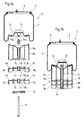
- the structure of the air spring 5 is particularly the representations in the figures 2a and 2b.
- Characteristic of the air spring 5 shown is the multi-part in the immersion direction Construction of the plunger 8 from several individual parts 8a and 8b, wherein only the part 8a can be fixed on the rolling bellows 7 and each have an identical design Parts 8b serve different heights of the plunger 8 and thus allow different spring travel without the entire plunger 8 remove and replace with another plunger 8.
- the plunger 8 is fixed on the bellows 7 in the illustrated Embodiment over one all parts 8a and 8b of the plunger 8 axially with each other connecting clamping element 11, which in this case with as the bellows side an externally threaded screw is formed, which in a threaded sleeve 17a can be screwed in, which in turn can be screwed onto a threaded pin 12a is.
- the threaded pin 12a is passed through an end cap 12 and connected to a buffer 13, preferably rubber, so that when screwing the clamping element 11, the end cap against the Plunger 8 is pulled.
- the holding plate 14 is for receiving the fastening means 10 for fixing the plunger 8 on the trailing arm 3 in the underside of the lower part 8b of the plunger 8 on the trailing arm side.
- one of the molds is in the underside of part 8b of plunger 8 recess 15 corresponding to the holding plate 14.
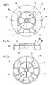
- the plunger 8 made, for example, as an injection molded part made of plastic circular outer surface 8c, from which a variety of substantially extend radially extending webs 8d towards the center of the plunger 8.
- the Plunger 8 on the central support body 17, in the illustrated embodiment each contain a pipe section 17b which can be inserted into the individual parts 8a, 8b.
- These pipe sections 17b of the individual parts 8a and 8b of the plunger 8 are arranged so that, as shown in Fig. 2b, in the assembled state form the support body 17.
- the plunger 8 supports the support body 17 directly on the holding plate 14 from.
- the support body 17 also conceivable instead of the individual pipe pieces 17b to provide a continuous piece of pipe.
- it is a piece of pipe that can be tipped into the plunger, the lower end of which rests on the holding plate 14, and the upper end of which the threaded pin 12a is screwed.
- the air spring 5 described above is characterized in that it due to the modular construction of the plunger 8 from several parts 8a and 8b is very simple and quick to add the plunger 8 or separating individual parts 8b to set different spring travel, without having to replace the entire plunger 8. Also for warehousing This configuration is advantageous because it is based on the storage of plungers 8 different heights can be dispensed with.
Landscapes
- Engineering & Computer Science (AREA)
- General Engineering & Computer Science (AREA)
- Mechanical Engineering (AREA)
- Vehicle Body Suspensions (AREA)
- Fluid-Damping Devices (AREA)
Abstract
Description
- Fig. 1
- eine Prinzipskizze einer Luftfederachse in teilweise eingefederter Lage;
- Fig. 2a
- eine Explosionszeichnung einer erfindungsgemäßen Luftfeder im Längsschnitt;
- Fig. 2b
- einen Längsschnitt durch die zusammengesetzte Luftfeder gemäß Fig. 2a;
- Fig. 3a
- eine Draufsicht auf ein Bauteil des Tauchkolbens;
- Fig. 3b
- eine Seitenansicht des Bauteils gemäß Fig. 3a und
- Fig. 3c
- eine Ansicht von unten des Bauteils gemäß Fig. 3a und 3b.
- 1
- Fahrzeugrahmen
- 2
- Konsole
- 3
- Längslenker
- 4
- Achskörper
- 5
- Luftfeder
- 6
- Deckel
- 7
- Rollbalg
- 8
- Tauchkolben
- 8a
- Teil
- 8b
- Teil
- 8c
- Mantelfläche
- 8d
- Steg
- 9
- Sprengring
- 10
- Befestigungsmittel
- 11
- Spannelement
- 12
- Abschlußkappe
- 12a
- Gewindestift
- 13
- Puffer
- 14
- Halteplatte
- 15
- Ausnehmung
- 16
- Vorsprung
- 17
- Stützkörper
- 17a
- Gewindehülse
- 17b
- Rohrstück
- 18
- Führungselement
Claims (15)
- Luftfeder für Luftfederachsen mit einem an einem Fahrzeugrahmen festlegbaren Deckel (6), einem auf einem rückwärtigen Ende eines Längslenkers (3) festlegbaren Tauchkolben (8) sowie einem zwischen Deckel (6) und Tauchkolben (8) angeordneten Rollbalg (7),
dadurch gekennzeichnet, daß der Tauchkolben (8) in Eintauchrichtung betrachtet mehrteilig ausgebildet ist. - Luftfeder nach Anspruch 1, dadurch gekennzeichnet, daß die einzelnen Teile (8a, 8b) des Tauchkolbens (8) zumindest formschlüssig miteinander verbindbar sind.
- Luftfeder nach Anspruch 1 oder 2, dadurch gekennzeichnet, daß zum Ausrichten und lagegenauen Positionieren der einzelnen Teile (8b) des Tauchkolbens (8) zueinander Führungselemente (18) an der Ober- und/oder Unterseite der einzelnen Teile (8b) des Tauchkolbens (8) ausgebildet sind.
- Luftfeder nach mindestens einem der Ansprüche 1 bis 3, dadurch gekennzeichnet, daß in jedem der einzelnen Teile (8a, 8b) des Tauchkolbens (8) eine in Eintauchrichtung des Tauchkolbens (8) verlaufende Stützkörper (17) derart angeordnet ist, daß die Stützkörper (17) der einzelnen Teile (8a, 8b) des Tauchkolbens (8) im montierten Zustand einen durchgehenden Stützkörper (17) bildend fluchtend aneinander liegen.
- Luftfeder nach Anspruch 4, dadurch gekennzeichnet, daß die Stützkörper (17) der einzelnen Teile (8a, 8b) des Tauchkolbens (8) eingearbeitete Rohrstücke (17b), z. B. aus Metall, aufweisen.
- Luftfeder nach Anspruch 4, dadurch gekennzeichnet, daß die Stützkörper (17) nur ein einschiebbares, durchgehendes Rohr aufnehmen.
- Luftfeder nach mindestens einem der Ansprüche 1 bis 6, dadurch gekennzeichnet, daß die einzelnen Teile (8a, 8b) des Tauchkolbens (8) aus Kunststoff, insbesondere glasfaserverstärktem Kunststoff, bestehen.
- Luftfeder nach mindestens einem der Ansprüche 1 bis 7, dadurch gekennzeichnet, daß der Tauchkolben (8) über eine Halteplatte (14) am Längslenker (3) festlegbar ist, wobei in der Unterseite jedes der einzelnen Teile (8a, 8b) des Tauchkolbens (8) eine der Form der Halteplatte (14) entsprechende Ausnehmung (15) ausgebildet ist.
- Luftfeder nach Anspruch 8, dadurch gekennzeichnet, daß sich der Stützkörper (17) des Tauchkolbens (8) mit seinem unteren Ende direkt auf der Halteplatte (14) abstützt.
- Luftfeder nach Anspruch 8, dadurch gekennzeichnet, daß auf der Oberseite aller nicht direkt mit dem Rollbalg (7) verbundenen Teile (8b) des Tauchkolbens (8) im wesentlichen der Form der Halteplatte (14) entsprechende Vorsprünge (16) ausgebildet sind, die im zusammengesetzten Zustand in die entsprechenden Ausnehmungen (15) in der Unterseite der anderen Teile (8a, 8b) des Tauchkolbens (8) eingreifen.
- Luftfeder nach Anspruch 9 oder 10, dadurch gekennzeichnet, daß die Ausnehmungen (15) zur Aufnahme der Halteplatte (14) sowie der Vorsprünge (16) so in den Unterseiten der einzelnen Teile (8a, 8b) des Tauchkolbens (8) ausgebildet sind, daß die einzelnen Teile (8a, 8b) des Tauchkolbens (8) in nur einer Position aufeinander bzw. auf die Halteplatte (14) aufsetzbar sind.
- Luftfeder nach mindestens einem der Ansprüche 1 bis 11, dadurch gekennzeichnet, daß die einzelnen Teile (8a, 8b) des Tauchkolbens (8) über ein Spannelement (11) miteinander verbindbar sind.
- Luftfeder nach Anspruch 12,dadurch gekennzeichnet, daß der Tauchkolben (8) gleichzeitig über das Spannelement (11) am Rollbalg (7) festlegbar ist.
- Luftfeder nach Anspruch 12 oder 13, dadurch gekennzeichnet, daß die Halteplatte (14) gleichzeitig über das Spannelement (11) am Tauchkolben (8) festlegbar ist.
- Luftfeder nach mindestens einem der Ansprüche 1 bis 11, dadurch gekennzeichnet, daß die einzelnen Teile (8a, 8b) des Tauchkolbens (8) ein im Querschnitt festigkeitsoptimiertes Profil mit einer kreisförmigen Mantelfläche einem zentralen Stützkörper (17) aufweisen, wobei der Stützkörper (17) und die Mantelfläche (8c) über im wesentlichen radial verlaufende Stege (8d) miteinander verbunden sind.
Applications Claiming Priority (2)
| Application Number | Priority Date | Filing Date | Title |
|---|---|---|---|
| DE10149057 | 2001-10-05 | ||
| DE10149057.7A DE10149057B4 (de) | 2001-10-05 | 2001-10-05 | Tauchkolben für eine Luftfeder |
Publications (3)
| Publication Number | Publication Date |
|---|---|
| EP1300264A2 true EP1300264A2 (de) | 2003-04-09 |
| EP1300264A3 EP1300264A3 (de) | 2004-08-25 |
| EP1300264B1 EP1300264B1 (de) | 2006-04-19 |
Family
ID=7701435
Family Applications (1)
| Application Number | Title | Priority Date | Filing Date |
|---|---|---|---|
| EP02022068A Expired - Lifetime EP1300264B1 (de) | 2001-10-05 | 2002-10-02 | Luftfeder für eine Fahrzeugachsaufhängung |
Country Status (4)
| Country | Link |
|---|---|
| EP (1) | EP1300264B1 (de) |
| AT (1) | ATE323614T1 (de) |
| DE (2) | DE10149057B4 (de) |
| ES (1) | ES2262739T3 (de) |
Cited By (19)
| Publication number | Priority date | Publication date | Assignee | Title |
|---|---|---|---|---|
| WO2006107456A1 (en) * | 2005-04-01 | 2006-10-12 | Bfs Diversified Products, Llc | Self-indexing spacer for air spring assembly |
| WO2007103472A1 (en) * | 2006-03-08 | 2007-09-13 | Bfs Diversified Products, Llc | Fluid spring assembly and method |
| DE102006032383B3 (de) * | 2006-07-13 | 2007-11-22 | Hermann Peters Gmbh & Co. | Leichtbau-Tauchkolben |
| FR2901736A1 (fr) * | 2005-12-01 | 2007-12-07 | Peugeot Citroen Automobiles Sa | Dispositif d'adaptation pour un train avant d'un vehicule automobile et vehicule automobile comportant un tel dispositif |
| WO2008025517A1 (de) * | 2006-08-30 | 2008-03-06 | Lkh-Kunststoffwerk Gmbh & Co. Kg | Tauchkolben für eine luftfeder |
| WO2009015821A1 (de) * | 2007-07-27 | 2009-02-05 | Lkh-Kunststoffwerk Gmbh & Co. Kg | Tauchkolben |
| WO2009148812A3 (en) * | 2008-06-05 | 2010-03-04 | Firestone Industrial Products Company, Llc | Gas spring assembly and spacer |
| EP2236852A3 (de) * | 2009-04-01 | 2011-07-06 | Firestone Industrial Products Company, LLC | Gasfederanordnung und Aufhängungssystem damit |
| WO2011093807A1 (en) * | 2010-01-26 | 2011-08-04 | Aktas Hava Suspansiyon Sistemleri Sanayi Ve Ticaret Anonim Sirketi | Bottom plate with bumper, made of thermoplastic material, used at air suspension systems |
| DE102011085323A1 (de) * | 2011-02-11 | 2012-08-16 | Continental Teves Ag & Co. Ohg | Kolben für eine Luftfeder |
| WO2013117429A3 (de) * | 2012-02-07 | 2013-11-21 | Saf-Holland Gmbh | Luftfederbefestigung |
| EP2563607A4 (de) * | 2010-04-26 | 2014-04-16 | Firestone Ind Products Co Llc | Gasfederanordnung und montageverfahren dafür |
| EP2034210A3 (de) * | 2007-09-06 | 2014-05-21 | BFS Diversified Products, LLC. | Modularer Luftfederkolben |
| US20140252703A1 (en) * | 2011-10-10 | 2014-09-11 | Contitech Luftfedersysteme Gmbh | Roll-off piston for an air spring rolling-lobe flexible member |
| EP2710276A4 (de) * | 2011-05-17 | 2015-08-26 | Hendrickson Usa Llc | Kolben für eine luftfeder eines schwerlastfahrzeugs |
| CN107848357A (zh) * | 2015-05-29 | 2018-03-27 | 塞夫霍兰德有限公司 | 支撑单元 |
| US10119590B2 (en) * | 2014-07-21 | 2018-11-06 | Firestone Industrial Products Company, Llc | End member assemblies as well as gas spring assemblies and suspension systems including same |
| FR3102523A1 (fr) * | 2019-10-29 | 2021-04-30 | Safran Landing Systems | Pointeau de dosage pour amortisseur de type oléopneumatique |
| CN113459749A (zh) * | 2021-07-12 | 2021-10-01 | 北京汽车股份有限公司 | 一种空气弹簧安装检测装置、安装结构及汽车 |
Families Citing this family (7)
| Publication number | Priority date | Publication date | Assignee | Title |
|---|---|---|---|---|
| DE102008010469A1 (de) * | 2008-02-21 | 2009-08-27 | Bpw Bergische Achsen Kg | Luftfeder für eine luftgefederte Fahrzeugachse |
| EP2300248B1 (de) * | 2008-06-05 | 2018-11-28 | Firestone Industrial Products Company, LLC | Gasfederkolben mit teilbalgstützmerkmal und gasfederanordnung damit |
| US8191458B2 (en) | 2008-07-02 | 2012-06-05 | Firestone Industrial Products Company, Llc | Gas spring piston with partial bellows support feature and gas spring assembly including same |
| DE202012104483U1 (de) | 2012-11-20 | 2012-12-10 | Contitech Luftfedersysteme Gmbh | Mehrteiliger Abrollkolben für einen Luftfederrollbalg |
| US10005333B2 (en) | 2013-05-28 | 2018-06-26 | Firestone Industrial Products Company, Llc | End member assemblies and travel-restraint assemblies as well as gas spring assemblies including same |
| DE102023111790A1 (de) * | 2023-05-05 | 2024-11-07 | Bpw Bergische Achsen Kommanditgesellschaft | Luftfeder für eine Luftfederachse und Pufferelement |
| DE102024108205B4 (de) * | 2024-03-21 | 2026-03-26 | Vibracoustic Se | Dämpferkappe, Bausatz sowie Luftfedereinheit |
Citations (2)
| Publication number | Priority date | Publication date | Assignee | Title |
|---|---|---|---|---|
| DE3147231C1 (de) | 1981-11-28 | 1983-03-31 | Bergische Achsenfabrik Fr. Kotz & Söhne, 5276 Wiehl | Luftfeder |
| EP0864453A1 (de) | 1997-03-15 | 1998-09-16 | BPW Bergische Achsen Kommanditgesellschaft | Luftfeder für Luftfederachsen |
Family Cites Families (6)
| Publication number | Priority date | Publication date | Assignee | Title |
|---|---|---|---|---|
| EP0160371A1 (de) * | 1984-03-20 | 1985-11-06 | Norde Suspensions Limited | Fahrzeugaufhängungssystem |
| DE3824542A1 (de) * | 1988-07-20 | 1990-01-25 | Sauer Achsenfab | Tauchkolbenanordnung |
| DE3907462A1 (de) * | 1989-03-08 | 1990-09-13 | Continental Ag | Rollbalg-luftfeder |
| DE29615901U1 (de) * | 1996-09-12 | 1996-10-24 | BPW Bergische Achsen Kommanditgesellschaft, 51674 Wiehl | Luftfeder |
| DE29619081U1 (de) * | 1996-11-04 | 1997-01-09 | ContiTech Luftfedersysteme GmbH, 30165 Hannover | Rollbalg-Luftfeder |
| JPH10324126A (ja) * | 1997-05-26 | 1998-12-08 | Isuzu Motors Ltd | 車両用サスペンション装置 |
-
2001
- 2001-10-05 DE DE10149057.7A patent/DE10149057B4/de not_active Expired - Fee Related
-
2002
- 2002-10-02 EP EP02022068A patent/EP1300264B1/de not_active Expired - Lifetime
- 2002-10-02 DE DE50206450T patent/DE50206450D1/de not_active Expired - Lifetime
- 2002-10-02 AT AT02022068T patent/ATE323614T1/de not_active IP Right Cessation
- 2002-10-02 ES ES02022068T patent/ES2262739T3/es not_active Expired - Lifetime
Patent Citations (2)
| Publication number | Priority date | Publication date | Assignee | Title |
|---|---|---|---|---|
| DE3147231C1 (de) | 1981-11-28 | 1983-03-31 | Bergische Achsenfabrik Fr. Kotz & Söhne, 5276 Wiehl | Luftfeder |
| EP0864453A1 (de) | 1997-03-15 | 1998-09-16 | BPW Bergische Achsen Kommanditgesellschaft | Luftfeder für Luftfederachsen |
Cited By (35)
| Publication number | Priority date | Publication date | Assignee | Title |
|---|---|---|---|---|
| WO2006107456A1 (en) * | 2005-04-01 | 2006-10-12 | Bfs Diversified Products, Llc | Self-indexing spacer for air spring assembly |
| EP2292453A3 (de) * | 2005-04-01 | 2011-03-23 | BFS Diversified Products, LLC | Selbst-Indexierung-Abstandshalter für Luftfederung |
| US7806391B2 (en) | 2005-04-01 | 2010-10-05 | Bfs Diversified Products, Llc | Self-indexing spacer for air spring assembly |
| RU2381913C2 (ru) * | 2005-04-01 | 2010-02-20 | БиЭфЭс Дайверсифайд Продактс, ЭлЭлСи | Прокладка пневматической рессоры |
| US7328887B2 (en) | 2005-04-01 | 2008-02-12 | Bfs Diversified Products, Llc | Self-indexing spacer for air spring assembly |
| FR2901736A1 (fr) * | 2005-12-01 | 2007-12-07 | Peugeot Citroen Automobiles Sa | Dispositif d'adaptation pour un train avant d'un vehicule automobile et vehicule automobile comportant un tel dispositif |
| US7530554B2 (en) | 2006-03-08 | 2009-05-12 | Bfs Diversified Products, Llc | Fluid spring assembly and method |
| WO2007103472A1 (en) * | 2006-03-08 | 2007-09-13 | Bfs Diversified Products, Llc | Fluid spring assembly and method |
| EP1878939A3 (de) * | 2006-07-13 | 2008-01-23 | Hermann Peters GmbH & Co. | Leichtbau-Tauchkolben |
| DE102006032383B3 (de) * | 2006-07-13 | 2007-11-22 | Hermann Peters Gmbh & Co. | Leichtbau-Tauchkolben |
| WO2008025517A1 (de) * | 2006-08-30 | 2008-03-06 | Lkh-Kunststoffwerk Gmbh & Co. Kg | Tauchkolben für eine luftfeder |
| WO2009015821A1 (de) * | 2007-07-27 | 2009-02-05 | Lkh-Kunststoffwerk Gmbh & Co. Kg | Tauchkolben |
| US20100127438A1 (en) * | 2007-07-27 | 2010-05-27 | Martin Eise | Plunger piston |
| US9689455B2 (en) | 2007-09-06 | 2017-06-27 | Firestone Industrial Products Company, Llc | Air spring modular piston |
| US9261157B2 (en) | 2007-09-06 | 2016-02-16 | Firestone Industrial Products Company, Llc | Air spring modular piston |
| EP2034210A3 (de) * | 2007-09-06 | 2014-05-21 | BFS Diversified Products, LLC. | Modularer Luftfederkolben |
| US8231113B2 (en) | 2008-06-05 | 2012-07-31 | Firestone Industrial Products Company, Llc | Gas spring assembly and spacer |
| WO2009148812A3 (en) * | 2008-06-05 | 2010-03-04 | Firestone Industrial Products Company, Llc | Gas spring assembly and spacer |
| US8613430B2 (en) | 2009-04-01 | 2013-12-24 | Firestone Industrial Products Company, Llc | Gas spring assembly and suspension system including same |
| EP2236852A3 (de) * | 2009-04-01 | 2011-07-06 | Firestone Industrial Products Company, LLC | Gasfederanordnung und Aufhängungssystem damit |
| WO2011093807A1 (en) * | 2010-01-26 | 2011-08-04 | Aktas Hava Suspansiyon Sistemleri Sanayi Ve Ticaret Anonim Sirketi | Bottom plate with bumper, made of thermoplastic material, used at air suspension systems |
| EP2563607A4 (de) * | 2010-04-26 | 2014-04-16 | Firestone Ind Products Co Llc | Gasfederanordnung und montageverfahren dafür |
| US9555684B2 (en) | 2010-04-26 | 2017-01-31 | Firestone Industrial Products Company, Llc | Gas spring assembly and method of assembling same |
| US8979075B2 (en) | 2010-04-26 | 2015-03-17 | Firestone Industrial Products Company, Llc | Gas spring assembly and method of assembling same |
| DE102011085323A1 (de) * | 2011-02-11 | 2012-08-16 | Continental Teves Ag & Co. Ohg | Kolben für eine Luftfeder |
| US9157529B2 (en) | 2011-05-17 | 2015-10-13 | Hendrickson Usa, L.L.C. | Piston for an air spring of a heavy-duty vehicle |
| EP2710276A4 (de) * | 2011-05-17 | 2015-08-26 | Hendrickson Usa Llc | Kolben für eine luftfeder eines schwerlastfahrzeugs |
| US20140252703A1 (en) * | 2011-10-10 | 2014-09-11 | Contitech Luftfedersysteme Gmbh | Roll-off piston for an air spring rolling-lobe flexible member |
| US9709122B2 (en) * | 2011-10-10 | 2017-07-18 | Contitech Luftfedersysteme Gmbh | Roll-off piston for an air spring rolling-lobe flexible member |
| WO2013117429A3 (de) * | 2012-02-07 | 2013-11-21 | Saf-Holland Gmbh | Luftfederbefestigung |
| US10119590B2 (en) * | 2014-07-21 | 2018-11-06 | Firestone Industrial Products Company, Llc | End member assemblies as well as gas spring assemblies and suspension systems including same |
| CN107848357A (zh) * | 2015-05-29 | 2018-03-27 | 塞夫霍兰德有限公司 | 支撑单元 |
| FR3102523A1 (fr) * | 2019-10-29 | 2021-04-30 | Safran Landing Systems | Pointeau de dosage pour amortisseur de type oléopneumatique |
| WO2021083913A1 (fr) * | 2019-10-29 | 2021-05-06 | Safran Landing Systems | Pointeau de dosage pour amortisseur de type oleopneumatique |
| CN113459749A (zh) * | 2021-07-12 | 2021-10-01 | 北京汽车股份有限公司 | 一种空气弹簧安装检测装置、安装结构及汽车 |
Also Published As
| Publication number | Publication date |
|---|---|
| DE50206450D1 (de) | 2006-05-24 |
| ES2262739T3 (es) | 2006-12-01 |
| DE10149057A1 (de) | 2003-04-30 |
| ATE323614T1 (de) | 2006-05-15 |
| EP1300264B1 (de) | 2006-04-19 |
| EP1300264A3 (de) | 2004-08-25 |
| DE10149057B4 (de) | 2021-05-12 |
Similar Documents
| Publication | Publication Date | Title |
|---|---|---|
| EP1300264B1 (de) | Luftfeder für eine Fahrzeugachsaufhängung | |
| EP0864453B1 (de) | Luftfeder für Luftfederachsen | |
| DE19721878A1 (de) | Vorderachse für ein Kraftfahrzeug | |
| DE3902407C1 (en) | Bearing | |
| DE19634215C2 (de) | Zentrallager für eine Hinterachse eines Kraftfahrzeuges | |
| EP0352541A1 (de) | Federnde Achsaufhängung für Kraftfahrzeuge, insbesondere Nutzfahrzeuge | |
| DE102019203366A1 (de) | Blattfederlager und Kraftfahrzeugradaufhängung mit einem solchen | |
| DE4320090C2 (de) | Gefederte Sattelstütze für ein Fahrrad | |
| EP0501132A1 (de) | Federbein für ein Kraftfahrzeug | |
| DE2447821C2 (de) | Unabhängige Radaufhängung für ein Kraftfahrzeug | |
| DE69519673T2 (de) | Dämpfungsvorrichtung für kraftfahrzeugstabilisatoren und verfahren zu ihrer befestigung | |
| DE1916578B2 (de) | Lenkgestänge für Kraftfahrzeuge | |
| EP1034949B1 (de) | Führungslenker für eine Kraftfahrzeugradaufhängung | |
| DE102009010571B4 (de) | Vorrichtung und Verfahren zur Montage einer Feder | |
| DE3138534C2 (de) | ||
| DE1240413B (de) | Einzelradaufhaengung und -federung fuer Fahrzeuge | |
| WO2004027284A1 (de) | Tauchkolben für eine luftfeder | |
| EP0531766A1 (de) | Schwingungstilger | |
| DE3741465C2 (de) | Stiftgelenkaufhängung eines Teleskopstoßdämpfers oder eines Federbeins für Kraftfahrzeuge | |
| DE8801613U1 (de) | Gummilager für Federn, Achsen und ähnliche Teile an Kraftfahrzeugen | |
| DE19748117A1 (de) | Kugelzapfen | |
| DE202018105298U1 (de) | Stabilisatorvorrichtung für Schienenfahrzeuge, insbesondere Wankstabilisatoren | |
| DE8235995U1 (de) | Federnder Träger für einen Stoßdämpfer einer vorderen Federung eines Fahrzeugs | |
| DE3905396C2 (de) | ||
| EP1806517A1 (de) | Elastomer-Metall-Gelenklager, insbesondere als Zentralgelenklager eines Dreieckslenkers zur Verbindung eines Achskörpers mit einem Fahrzeugaufbau |
Legal Events
| Date | Code | Title | Description |
|---|---|---|---|
| PUAI | Public reference made under article 153(3) epc to a published international application that has entered the european phase |
Free format text: ORIGINAL CODE: 0009012 |
|
| AK | Designated contracting states |
Kind code of ref document: A2 Designated state(s): AT BE BG CH CY CZ DE DK EE ES FI FR GB GR IE IT LI LU MC NL PT SE SK TR Designated state(s): AT BE BG CH CY CZ DE DK EE ES FI FR GB GR IE IT LI LU MC NL PT SE SK TR |
|
| AX | Request for extension of the european patent |
Extension state: AL LT LV MK RO SI |
|
| PUAL | Search report despatched |
Free format text: ORIGINAL CODE: 0009013 |
|
| AK | Designated contracting states |
Kind code of ref document: A3 Designated state(s): AT BE BG CH CY CZ DE DK EE ES FI FR GB GR IE IT LI LU MC NL PT SE SK TR |
|
| AX | Request for extension of the european patent |
Extension state: AL LT LV MK RO SI |
|
| 17P | Request for examination filed |
Effective date: 20041202 |
|
| 17Q | First examination report despatched |
Effective date: 20050301 |
|
| AKX | Designation fees paid |
Designated state(s): AT BE BG CH CY CZ DE DK EE ES FI FR GB GR IE IT LI LU MC NL PT SE SK TR |
|
| GRAP | Despatch of communication of intention to grant a patent |
Free format text: ORIGINAL CODE: EPIDOSNIGR1 |
|
| GRAS | Grant fee paid |
Free format text: ORIGINAL CODE: EPIDOSNIGR3 |
|
| GRAA | (expected) grant |
Free format text: ORIGINAL CODE: 0009210 |
|
| AK | Designated contracting states |
Kind code of ref document: B1 Designated state(s): AT BE BG CH CY CZ DE DK EE ES FI FR GB GR IE IT LI LU MC NL PT SE SK TR |
|
| PG25 | Lapsed in a contracting state [announced via postgrant information from national office to epo] |
Ref country code: IT Free format text: LAPSE BECAUSE OF FAILURE TO SUBMIT A TRANSLATION OF THE DESCRIPTION OR TO PAY THE FEE WITHIN THE PRESCRIBED TIME-LIMIT;WARNING: LAPSES OF ITALIAN PATENTS WITH EFFECTIVE DATE BEFORE 2007 MAY HAVE OCCURRED AT ANY TIME BEFORE 2007. THE CORRECT EFFECTIVE DATE MAY BE DIFFERENT FROM THE ONE RECORDED. Effective date: 20060419 Ref country code: CZ Free format text: LAPSE BECAUSE OF FAILURE TO SUBMIT A TRANSLATION OF THE DESCRIPTION OR TO PAY THE FEE WITHIN THE PRESCRIBED TIME-LIMIT Effective date: 20060419 Ref country code: FI Free format text: LAPSE BECAUSE OF FAILURE TO SUBMIT A TRANSLATION OF THE DESCRIPTION OR TO PAY THE FEE WITHIN THE PRESCRIBED TIME-LIMIT Effective date: 20060419 Ref country code: IE Free format text: LAPSE BECAUSE OF FAILURE TO SUBMIT A TRANSLATION OF THE DESCRIPTION OR TO PAY THE FEE WITHIN THE PRESCRIBED TIME-LIMIT Effective date: 20060419 Ref country code: SK Free format text: LAPSE BECAUSE OF FAILURE TO SUBMIT A TRANSLATION OF THE DESCRIPTION OR TO PAY THE FEE WITHIN THE PRESCRIBED TIME-LIMIT Effective date: 20060419 Ref country code: NL Free format text: LAPSE BECAUSE OF FAILURE TO SUBMIT A TRANSLATION OF THE DESCRIPTION OR TO PAY THE FEE WITHIN THE PRESCRIBED TIME-LIMIT Effective date: 20060419 |
|
| REG | Reference to a national code |
Ref country code: GB Ref legal event code: FG4D Free format text: NOT ENGLISH |
|
| GBT | Gb: translation of ep patent filed (gb section 77(6)(a)/1977) |
Effective date: 20060419 |
|
| REF | Corresponds to: |
Ref document number: 50206450 Country of ref document: DE Date of ref document: 20060524 Kind code of ref document: P |
|
| REG | Reference to a national code |
Ref country code: IE Ref legal event code: FG4D Free format text: LANGUAGE OF EP DOCUMENT: GERMAN |
|
| PG25 | Lapsed in a contracting state [announced via postgrant information from national office to epo] |
Ref country code: SE Free format text: LAPSE BECAUSE OF FAILURE TO SUBMIT A TRANSLATION OF THE DESCRIPTION OR TO PAY THE FEE WITHIN THE PRESCRIBED TIME-LIMIT Effective date: 20060719 Ref country code: DK Free format text: LAPSE BECAUSE OF FAILURE TO SUBMIT A TRANSLATION OF THE DESCRIPTION OR TO PAY THE FEE WITHIN THE PRESCRIBED TIME-LIMIT Effective date: 20060719 |
|
| PG25 | Lapsed in a contracting state [announced via postgrant information from national office to epo] |
Ref country code: PT Free format text: LAPSE BECAUSE OF FAILURE TO SUBMIT A TRANSLATION OF THE DESCRIPTION OR TO PAY THE FEE WITHIN THE PRESCRIBED TIME-LIMIT Effective date: 20060919 |
|
| NLV1 | Nl: lapsed or annulled due to failure to fulfill the requirements of art. 29p and 29m of the patents act | ||
| PG25 | Lapsed in a contracting state [announced via postgrant information from national office to epo] |
Ref country code: MC Free format text: LAPSE BECAUSE OF NON-PAYMENT OF DUE FEES Effective date: 20061031 Ref country code: CH Free format text: LAPSE BECAUSE OF NON-PAYMENT OF DUE FEES Effective date: 20061031 Ref country code: LI Free format text: LAPSE BECAUSE OF NON-PAYMENT OF DUE FEES Effective date: 20061031 |
|
| REG | Reference to a national code |
Ref country code: IE Ref legal event code: FD4D |
|
| ET | Fr: translation filed | ||
| REG | Reference to a national code |
Ref country code: ES Ref legal event code: FG2A Ref document number: 2262739 Country of ref document: ES Kind code of ref document: T3 |
|
| PLBE | No opposition filed within time limit |
Free format text: ORIGINAL CODE: 0009261 |
|
| STAA | Information on the status of an ep patent application or granted ep patent |
Free format text: STATUS: NO OPPOSITION FILED WITHIN TIME LIMIT |
|
| 26N | No opposition filed |
Effective date: 20070122 |
|
| REG | Reference to a national code |
Ref country code: CH Ref legal event code: PL |
|
| PG25 | Lapsed in a contracting state [announced via postgrant information from national office to epo] |
Ref country code: AT Free format text: LAPSE BECAUSE OF NON-PAYMENT OF DUE FEES Effective date: 20061002 |
|
| PG25 | Lapsed in a contracting state [announced via postgrant information from national office to epo] |
Ref country code: GR Free format text: LAPSE BECAUSE OF FAILURE TO SUBMIT A TRANSLATION OF THE DESCRIPTION OR TO PAY THE FEE WITHIN THE PRESCRIBED TIME-LIMIT Effective date: 20060720 |
|
| PG25 | Lapsed in a contracting state [announced via postgrant information from national office to epo] |
Ref country code: EE Free format text: LAPSE BECAUSE OF FAILURE TO SUBMIT A TRANSLATION OF THE DESCRIPTION OR TO PAY THE FEE WITHIN THE PRESCRIBED TIME-LIMIT Effective date: 20060419 Ref country code: BG Free format text: LAPSE BECAUSE OF FAILURE TO SUBMIT A TRANSLATION OF THE DESCRIPTION OR TO PAY THE FEE WITHIN THE PRESCRIBED TIME-LIMIT Effective date: 20060719 |
|
| PG25 | Lapsed in a contracting state [announced via postgrant information from national office to epo] |
Ref country code: LU Free format text: LAPSE BECAUSE OF NON-PAYMENT OF DUE FEES Effective date: 20061002 |
|
| PG25 | Lapsed in a contracting state [announced via postgrant information from national office to epo] |
Ref country code: CY Free format text: LAPSE BECAUSE OF FAILURE TO SUBMIT A TRANSLATION OF THE DESCRIPTION OR TO PAY THE FEE WITHIN THE PRESCRIBED TIME-LIMIT Effective date: 20060419 |
|
| REG | Reference to a national code |
Ref country code: DE Ref legal event code: R082 Ref document number: 50206450 Country of ref document: DE Representative=s name: BUNGARTZ CHRISTOPHERSEN PARTNERSCHAFT MBB PATE, DE |
|
| REG | Reference to a national code |
Ref country code: FR Ref legal event code: PLFP Year of fee payment: 14 |
|
| REG | Reference to a national code |
Ref country code: FR Ref legal event code: PLFP Year of fee payment: 15 |
|
| REG | Reference to a national code |
Ref country code: FR Ref legal event code: PLFP Year of fee payment: 16 |
|
| REG | Reference to a national code |
Ref country code: FR Ref legal event code: PLFP Year of fee payment: 17 |
|
| PGFP | Annual fee paid to national office [announced via postgrant information from national office to epo] |
Ref country code: TR Payment date: 20180919 Year of fee payment: 17 |
|
| PGFP | Annual fee paid to national office [announced via postgrant information from national office to epo] |
Ref country code: DE Payment date: 20191107 Year of fee payment: 18 |
|
| PGFP | Annual fee paid to national office [announced via postgrant information from national office to epo] |
Ref country code: FR Payment date: 20191022 Year of fee payment: 18 Ref country code: IT Payment date: 20191021 Year of fee payment: 18 Ref country code: BE Payment date: 20191022 Year of fee payment: 18 Ref country code: ES Payment date: 20191120 Year of fee payment: 18 |
|
| PGFP | Annual fee paid to national office [announced via postgrant information from national office to epo] |
Ref country code: GB Payment date: 20191023 Year of fee payment: 18 |
|
| REG | Reference to a national code |
Ref country code: DE Ref legal event code: R119 Ref document number: 50206450 Country of ref document: DE |
|
| GBPC | Gb: european patent ceased through non-payment of renewal fee |
Effective date: 20201002 |
|
| REG | Reference to a national code |
Ref country code: BE Ref legal event code: MM Effective date: 20201031 |
|
| PG25 | Lapsed in a contracting state [announced via postgrant information from national office to epo] |
Ref country code: DE Free format text: LAPSE BECAUSE OF NON-PAYMENT OF DUE FEES Effective date: 20210501 Ref country code: FR Free format text: LAPSE BECAUSE OF NON-PAYMENT OF DUE FEES Effective date: 20201031 |
|
| PG25 | Lapsed in a contracting state [announced via postgrant information from national office to epo] |
Ref country code: GB Free format text: LAPSE BECAUSE OF NON-PAYMENT OF DUE FEES Effective date: 20201002 Ref country code: BE Free format text: LAPSE BECAUSE OF NON-PAYMENT OF DUE FEES Effective date: 20201031 |
|
| PG25 | Lapsed in a contracting state [announced via postgrant information from national office to epo] |
Ref country code: IT Free format text: LAPSE BECAUSE OF NON-PAYMENT OF DUE FEES Effective date: 20201002 |
|
| REG | Reference to a national code |
Ref country code: ES Ref legal event code: FD2A Effective date: 20220119 |
|
| PG25 | Lapsed in a contracting state [announced via postgrant information from national office to epo] |
Ref country code: ES Free format text: LAPSE BECAUSE OF NON-PAYMENT OF DUE FEES Effective date: 20201003 |
|
| PG25 | Lapsed in a contracting state [announced via postgrant information from national office to epo] |
Ref country code: TR Free format text: LAPSE BECAUSE OF NON-PAYMENT OF DUE FEES Effective date: 20201002 |