EP1298679B1 - Pilote électro-pneumatique - Google Patents
Pilote électro-pneumatique Download PDFInfo
- Publication number
- EP1298679B1 EP1298679B1 EP02292342A EP02292342A EP1298679B1 EP 1298679 B1 EP1298679 B1 EP 1298679B1 EP 02292342 A EP02292342 A EP 02292342A EP 02292342 A EP02292342 A EP 02292342A EP 1298679 B1 EP1298679 B1 EP 1298679B1
- Authority
- EP
- European Patent Office
- Prior art keywords
- pilot
- movable core
- passage
- flow ring
- casing
- Prior art date
- Legal status (The legal status is an assumption and is not a legal conclusion. Google has not performed a legal analysis and makes no representation as to the accuracy of the status listed.)
- Expired - Lifetime
Links
- 239000012530 fluid Substances 0.000 claims description 11
- 230000004907 flux Effects 0.000 abstract description 5
- 239000007789 gas Substances 0.000 abstract 1
- 230000009977 dual effect Effects 0.000 description 2
- 238000005457 optimization Methods 0.000 description 2
- RYGMFSIKBFXOCR-UHFFFAOYSA-N Copper Chemical compound [Cu] RYGMFSIKBFXOCR-UHFFFAOYSA-N 0.000 description 1
- 230000000712 assembly Effects 0.000 description 1
- 238000000429 assembly Methods 0.000 description 1
- 230000000295 complement effect Effects 0.000 description 1
- 239000000470 constituent Substances 0.000 description 1
- 229910052802 copper Inorganic materials 0.000 description 1
- 239000010949 copper Substances 0.000 description 1
- 230000008878 coupling Effects 0.000 description 1
- 238000010168 coupling process Methods 0.000 description 1
- 238000005859 coupling reaction Methods 0.000 description 1
Images


Classifications
-
- H—ELECTRICITY
- H01—ELECTRIC ELEMENTS
- H01F—MAGNETS; INDUCTANCES; TRANSFORMERS; SELECTION OF MATERIALS FOR THEIR MAGNETIC PROPERTIES
- H01F7/00—Magnets
- H01F7/06—Electromagnets; Actuators including electromagnets
- H01F7/08—Electromagnets; Actuators including electromagnets with armatures
- H01F7/10—Electromagnets; Actuators including electromagnets with armatures specially adapted for alternating current
- H01F7/12—Electromagnets; Actuators including electromagnets with armatures specially adapted for alternating current having anti-chattering arrangements
- H01F7/1205—Electromagnets; Actuators including electromagnets with armatures specially adapted for alternating current having anti-chattering arrangements having short-circuited conductors
Definitions
- the present invention relates to improvements made to electro-pneumatic drivers. It is aimed more particularly at a pilot of small dimensions (that is to say having a length of the order of 3 cm), and of low power, having standard electrical interfaces and pneumatic simple to set up, which allows to make sets of the cartridge type.
- An electromagnetically controlled valve having a ring and an opening for the passage of fluid is known to the US-A-5,127,625 .
- the technical problem to be solved by the invention is that of obtaining excellent optimization of the magnetic circuit and the fluid circuit, this with a small increase in the cost price.
- an electro-pneumatic pilot characterized in that it comprises a flux ring interposed between the movable core, the caliper and the carcass of the electromagnetic subset of the pilot. , said ring bearing on the return spring of the movable core and being provided with a longitudinal slot cooperating with corresponding passages provided in the carcass, between the movable core and the latter, for the passage of the fluid towards the pilot's exhaust .
- the carcass has an elliptically shaped cross-section and its bore for receiving the movable core is provided with side channels for the passage of fluid towards the exhaust, these channels communicating with each other. with the slot of the flow ring.
- the electrical interface of the electromagnetic subset of the driver is achieved by means of two poles that can be connected to standard printed circuit connectors.
- the pilot comprises, as known, an electromagnetic subset designated by the reference 10, on which a pneumatic switching sub-assembly 12 is mounted.
- This sub-assembly comprises the pressure admission channel 14 and the way of use 13 and a valve 15 serving as a closure member to the pressure admission path 14, the valve 15 being mounted in a plate 16 in which is formed the seat of the valve.
- the electromagnetic subassembly 10 comprises a carcass 17 receiving the coil 18 of the electromagnet, the internal bore of the carcass 17 receiving the fixed yoke 19 and the movable core 20 of the electromagnet.
- This movable core 20 is biased by a spring 21.
- the constituent elements of this subset 10 are held in a stirrup 22.
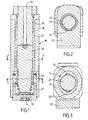
- a flow ring 23 is interposed between the movable core 20, the stirrup 22 and the carcass 17, this ring coming to bear on the spring 21 of the movable core 20, as can be clearly seen in FIGS. figures 1 and 4 .
- the flux ring 23 has a longitudinal slot 24 (see FIG. figures 2 and 4 ) to allow the passage of the fluid to the exhaust path 25.
- the carcass 17 has side channels 26 opening on the one hand on the slot 24 and on the other hand on the exhaust 25.
- the slot 24 is sized to obtain the required flow rate on the escape route 25.
- the flow ring 23 held by the spring 21 of the movable core 20, sufficiently out of its housing in the caliper 22 to allow passage of the fluid despite the presence of the spring 21.
- the flux ring also participates in the centering of the various elements described above, constituting the electromagnetic subset 10 of the driver according to the present invention.
- the carcass 17 has a section of substantially elliptical shape (see FIG. figure 3 ).
- the lateral channels 26 communicating with the slot 24 of the flow ring 23, are formed longitudinally in the bore of the carcass 17 receiving the movable core 20. This characteristic, that is to say the elliptical section of the carcass 17 , allows for the same width, to easily achieve the fluid passages and increase the volume of the copper coil 18.
- the electrical interface of the electromagnetic subassembly 10 is made via two pins such as 27 that can be connected to standard printed circuit connectors.
- the invention makes it possible to produce assemblies constituted by the coupling and the assembly of several pilots as described above.
- a dual pilot in which each of the pilots 30, 30 'has the characteristics of the pilot illustrated by the Figures 1 to 4 .
Landscapes
- Physics & Mathematics (AREA)
- Electromagnetism (AREA)
- Engineering & Computer Science (AREA)
- Power Engineering (AREA)
- Magnetically Actuated Valves (AREA)
- Supply Devices, Intensifiers, Converters, And Telemotors (AREA)
- Control Of The Air-Fuel Ratio Of Carburetors (AREA)
- Adhesives Or Adhesive Processes (AREA)
- Electric Double-Layer Capacitors Or The Like (AREA)
Description
- La présente invention est relative à des perfectionnements apportés à des pilotes électro-pneumatiques. Elle vise plus particulièrement un pilote de petites dimensions (c'est-à-dire présentant une longueur de l'ordre de 3 cm), et de faible puissance, ayant des interfaces électrique standard et pneumatique simple à mettre en place, ce qui permet de réaliser des ensembles du type cartouche. Une soupape à commande électromagnétique comportant une bague et une ouverture pour le passage de fluide est connue de la
US -A-5 127 625 . - Le problème technique qu'entend résoudre l'invention est celui qui consiste à obtenir une excellente optimisation du circuit magnétique et du circuit de fluide, ceci avec une faible augmentation du prix de revient.
- La solution à ce problème technique est apportée, selon la présente invention, par un pilote électro-pneumatique caractérisé en ce qu'il comporte une bague de flux interposée entre le noyau mobile, l'étrier et la carcasse du sous-ensemble électromagnétique du pilote, ladite bague prenant appui sur le ressort de rappel du noyau mobile et étant munie d'une fente longitudinale coopérant avec des passages correspondants prévus dans la carcasse, entre le noyau mobile et cette dernière, pour le passage du fluide vers l'échappement du pilote.
- Selon un mode de réalisation préféré de la présente invention, la carcasse présente une section de forme elliptique et l'on ménage dans son alésage destiné à recevoir le noyau mobile, des canaux latéraux pour le passage du fluide vers l'échappement, ces canaux communiquant avec la fente de la bague de flux.
- Selon la présente invention, l'interface électrique du sous-ensemble électromagnétique du pilote est réalisée par l'intermédiaire de deux pinoches pouvant se brancher sur des connecteurs de circuits imprimés standard.
- D'autres caractéristiques et avantages de la présente invention ressortiront de la description faite ci-après, en référence aux dessins annexés qui en illustrent un exemple de réalisation dépourvu de tout caractère limitatif. Sur les dessins :
- la
figure 1 est une coupe axiale longitudinale d'un pilote électro-pneumatique selon la présente invention ; - la
figure 2 est une coupe selon 2-2 de lafigure 1 ; - la
figure 3 est une coupe selon 3-3 de lafigure 1 ; - la
figure 4 est une coupe axiale verticale, passant par l'étrier du sous-ensemble électro-magnétique du pilote illustré par lafigure 1 ; - la
figure 5 est une coupe selon 5-5 de lafigure 6 représentant un double pilote réalisé conformément à l'invention, par l'assemblage de deux pilotes selon lesfigures 1 à 4 et - la
figure 6 est une coupe selon 6-6 de lafigure 5 . - En se référant aux dessins et plus particulièrement aux
figures 1 à 4 , on voit que le pilote selon la présente invention comporte comme connu un sous-ensemble électromagnétique désigné par la référence 10, sur lequel vient se monter un sous-ensemble de commutation pneumatique 12. Ce dernier comporte la voie d'admission de pression 14 et la voie d'utilisation 13 ainsi qu'un clapet 15 servant d'organe d'obturation à la voie d'admission de pression 14, ce clapet 15 étant monté dans une plaque 16 dans laquelle est ménagé le siège de ce clapet. - Le sous-ensemble électromagnétique 10 comporte une carcasse 17 recevant la bobine 18 de l'électro-aimant, l'alésage interne de la carcasse 17 recevant la culasse fixe 19 ainsi que le noyau mobile 20 de l'électro-aimant. Ce noyau mobile 20 est rappelé par un ressort 21. Les éléments constitutifs de ce sous-ensemble 10 sont maintenus dans un étrier 22. Il s'agit là de dispositions connues de l'Homme de l'art et pour ces raisons, toute description complémentaire paraît superflue.
- Selon la présente invention, on interpose une bague de flux 23 entre le noyau mobile 20, l'étrier 22 et la carcasse 17, cette bague venant prendre appui sur le ressort 21 du noyau mobile 20, ainsi qu'on le voit clairement sur les
figures 1 et4 . La bague de flux 23 comporte une fente longitudinale 24 (voir lesfigures 2 et4 ) de façon à permettre le passage du fluide vers la voie d'échappement 25. A cet effet, la carcasse 17 comporte des canaux latéraux 26 débouchant d'une part sur la fente 24 et d'autre part sur l'échappement 25. Grâce à cette disposition, on obtient une meilleure optimisation du circuit magnétique et du circuit de fluide, pour un faible surcoût dû à la présence de la bague de flux fendue, cette dernière permettant le passage du fluide dans la culasse. - Selon la présente invention, la fente 24 est dimensionnée de façon à obtenir le débit requis sur la voie d'échappement 25. La bague de flux 23 maintenue par le ressort 21 du noyau mobile 20, sort suffisamment de son logement dans l'étrier 22 pour permettre un passage du fluide malgré la présence du ressort 21. On notera que la bague de flux participe également au centrage des divers éléments décrits ci-dessus, constituant le sous-ensemble électromagnétique 10 du pilote selon la présente invention.
- Dans l'exemple de réalisation illustré ici, la carcasse 17 présente une section de forme sensiblement elliptique (voir la
figure 3 ). Les canaux latéraux 26 communiquant avec la fente 24 de la bague de flux 23, sont ménagés longitudinalement dans l'alésage de la carcasse 17 recevant le noyau mobile 20. Cette caractéristique, c'est-à-dire la section elliptique de la carcasse 17, permet, pour une même largeur, de réaliser facilement les passages de fluide et d'augmenter le volume du cuivre de la bobine 18. - L'interface électrique du sous-ensemble électromagnétique 10 est réalisée par l'intermédiaire de deux pinoches telles que 27 pouvant se brancher sur des connecteurs de circuits imprimés standard.
- L'invention permet notamment de réaliser des ensembles constitués par le couplage et l'assemblage de plusieurs pilotes tels que décrits ci-dessus. Ainsi, on a représenté sur les
figures 5 et 6 , une double pilote dans lequel chacun des pilotes 30, 30' présente les caractéristiques du pilote illustré par lesfigures 1 à 4 . - Il demeure bien entendu que la présente invention n'est pas limitée aux exemples de réalisation décrits et représentés ci-dessus, mais qu'elle en englobe toutes les variantes.
Claims (3)
- Pilote électro-pneumatique, caractérisé en ce qu'il comporte une bague de flux (23) interposée entre le noyau mobile (20), l'étrier (22) et la carcasse (17), du sous-ensemble électromagnétique (10) du pilote, cette bague de flux (23) prenant appui sur le ressort de rappel (21) du noyau (20) et étant munie d'une fente longitudinale (24) coopérant avec des passages correspondants (26) prévus dans la carcasse (17), entre le noyau (20) et cette dernière, pour le passage du fluide vers l'échappement (25).
- Pilote électro-pneumatique selon la revendication 1, caractérisé en ce que la carcasse (17) présente une section de forme elliptique et elle comporte, dans son alésage destiné à recevoir le noyau mobile (20), des canaux latéraux (26) qui communiquent avec la fente (24) de la bague de flux (23), pour permettre le passage du fluide vers l'échappement (25).
- Pilote électro-pneumatique selon l'une des revendications 1 ou 2, caractérisé en ce que l'interface électrique du sous-ensemble électromagnétique (10) est réalisée par l'intermédiaire de deux pinoches (27) pouvant se brancher sur des connecteurs de circuits imprimés standard.
Applications Claiming Priority (2)
| Application Number | Priority Date | Filing Date | Title |
|---|---|---|---|
| FR0112609A FR2830368B1 (fr) | 2001-10-01 | 2001-10-01 | Pilote electro-pneumatique |
| FR0112609 | 2001-10-01 |
Publications (2)
| Publication Number | Publication Date |
|---|---|
| EP1298679A1 EP1298679A1 (fr) | 2003-04-02 |
| EP1298679B1 true EP1298679B1 (fr) | 2008-12-10 |
Family
ID=8867802
Family Applications (1)
| Application Number | Title | Priority Date | Filing Date |
|---|---|---|---|
| EP02292342A Expired - Lifetime EP1298679B1 (fr) | 2001-10-01 | 2002-09-24 | Pilote électro-pneumatique |
Country Status (4)
| Country | Link |
|---|---|
| EP (1) | EP1298679B1 (fr) |
| AT (1) | ATE417351T1 (fr) |
| DE (1) | DE60230222D1 (fr) |
| FR (1) | FR2830368B1 (fr) |
Cited By (15)
| Publication number | Priority date | Publication date | Assignee | Title |
|---|---|---|---|---|
| US8839815B2 (en) | 2011-12-15 | 2014-09-23 | Honeywell International Inc. | Gas valve with electronic cycle counter |
| US8899264B2 (en) | 2011-12-15 | 2014-12-02 | Honeywell International Inc. | Gas valve with electronic proof of closure system |
| US8905063B2 (en) | 2011-12-15 | 2014-12-09 | Honeywell International Inc. | Gas valve with fuel rate monitor |
| US8947242B2 (en) | 2011-12-15 | 2015-02-03 | Honeywell International Inc. | Gas valve with valve leakage test |
| US9074770B2 (en) | 2011-12-15 | 2015-07-07 | Honeywell International Inc. | Gas valve with electronic valve proving system |
| US9234661B2 (en) | 2012-09-15 | 2016-01-12 | Honeywell International Inc. | Burner control system |
| US9557059B2 (en) | 2011-12-15 | 2017-01-31 | Honeywell International Inc | Gas valve with communication link |
| US9995486B2 (en) | 2011-12-15 | 2018-06-12 | Honeywell International Inc. | Gas valve with high/low gas pressure detection |
| US10024439B2 (en) | 2013-12-16 | 2018-07-17 | Honeywell International Inc. | Valve over-travel mechanism |
| US10203049B2 (en) | 2014-09-17 | 2019-02-12 | Honeywell International Inc. | Gas valve with electronic health monitoring |
| US10215291B2 (en) | 2013-10-29 | 2019-02-26 | Honeywell International Inc. | Regulating device |
| US10564062B2 (en) | 2016-10-19 | 2020-02-18 | Honeywell International Inc. | Human-machine interface for gas valve |
| US10697815B2 (en) | 2018-06-09 | 2020-06-30 | Honeywell International Inc. | System and methods for mitigating condensation in a sensor module |
| US10851993B2 (en) | 2011-12-15 | 2020-12-01 | Honeywell International Inc. | Gas valve with overpressure diagnostics |
| US11073281B2 (en) | 2017-12-29 | 2021-07-27 | Honeywell International Inc. | Closed-loop programming and control of a combustion appliance |
Families Citing this family (5)
| Publication number | Priority date | Publication date | Assignee | Title |
|---|---|---|---|---|
| US9846440B2 (en) | 2011-12-15 | 2017-12-19 | Honeywell International Inc. | Valve controller configured to estimate fuel comsumption |
| US9835265B2 (en) | 2011-12-15 | 2017-12-05 | Honeywell International Inc. | Valve with actuator diagnostics |
| US10422531B2 (en) | 2012-09-15 | 2019-09-24 | Honeywell International Inc. | System and approach for controlling a combustion chamber |
| US9841122B2 (en) | 2014-09-09 | 2017-12-12 | Honeywell International Inc. | Gas valve with electronic valve proving system |
| US10503181B2 (en) | 2016-01-13 | 2019-12-10 | Honeywell International Inc. | Pressure regulator |
Family Cites Families (3)
| Publication number | Priority date | Publication date | Assignee | Title |
|---|---|---|---|---|
| US2410320A (en) * | 1945-06-28 | 1946-10-29 | Phillips Control Corp | Shaded pole construction for solenoids |
| US4200972A (en) * | 1977-07-18 | 1980-05-06 | Robertshaw Controls Company | Method of manufacturing a solenoid |
| AT396622B (de) * | 1990-02-19 | 1993-10-25 | Avl Verbrennungskraft Messtech | Elektromagnetisch betätigbares ventil |
-
2001
- 2001-10-01 FR FR0112609A patent/FR2830368B1/fr not_active Expired - Fee Related
-
2002
- 2002-09-24 AT AT02292342T patent/ATE417351T1/de not_active IP Right Cessation
- 2002-09-24 DE DE60230222T patent/DE60230222D1/de not_active Expired - Lifetime
- 2002-09-24 EP EP02292342A patent/EP1298679B1/fr not_active Expired - Lifetime
Cited By (16)
| Publication number | Priority date | Publication date | Assignee | Title |
|---|---|---|---|---|
| US10697632B2 (en) | 2011-12-15 | 2020-06-30 | Honeywell International Inc. | Gas valve with communication link |
| US9557059B2 (en) | 2011-12-15 | 2017-01-31 | Honeywell International Inc | Gas valve with communication link |
| US8905063B2 (en) | 2011-12-15 | 2014-12-09 | Honeywell International Inc. | Gas valve with fuel rate monitor |
| US8947242B2 (en) | 2011-12-15 | 2015-02-03 | Honeywell International Inc. | Gas valve with valve leakage test |
| US9074770B2 (en) | 2011-12-15 | 2015-07-07 | Honeywell International Inc. | Gas valve with electronic valve proving system |
| US8899264B2 (en) | 2011-12-15 | 2014-12-02 | Honeywell International Inc. | Gas valve with electronic proof of closure system |
| US10851993B2 (en) | 2011-12-15 | 2020-12-01 | Honeywell International Inc. | Gas valve with overpressure diagnostics |
| US8839815B2 (en) | 2011-12-15 | 2014-09-23 | Honeywell International Inc. | Gas valve with electronic cycle counter |
| US9995486B2 (en) | 2011-12-15 | 2018-06-12 | Honeywell International Inc. | Gas valve with high/low gas pressure detection |
| US9234661B2 (en) | 2012-09-15 | 2016-01-12 | Honeywell International Inc. | Burner control system |
| US10215291B2 (en) | 2013-10-29 | 2019-02-26 | Honeywell International Inc. | Regulating device |
| US10024439B2 (en) | 2013-12-16 | 2018-07-17 | Honeywell International Inc. | Valve over-travel mechanism |
| US10203049B2 (en) | 2014-09-17 | 2019-02-12 | Honeywell International Inc. | Gas valve with electronic health monitoring |
| US10564062B2 (en) | 2016-10-19 | 2020-02-18 | Honeywell International Inc. | Human-machine interface for gas valve |
| US11073281B2 (en) | 2017-12-29 | 2021-07-27 | Honeywell International Inc. | Closed-loop programming and control of a combustion appliance |
| US10697815B2 (en) | 2018-06-09 | 2020-06-30 | Honeywell International Inc. | System and methods for mitigating condensation in a sensor module |
Also Published As
| Publication number | Publication date |
|---|---|
| DE60230222D1 (de) | 2009-01-22 |
| ATE417351T1 (de) | 2008-12-15 |
| EP1298679A1 (fr) | 2003-04-02 |
| FR2830368A1 (fr) | 2003-04-04 |
| FR2830368B1 (fr) | 2003-12-19 |
Similar Documents
| Publication | Publication Date | Title |
|---|---|---|
| EP1298679A1 (fr) | Pilote électro-pneumatique | |
| JP2004505217A (ja) | 特に自動車の液圧的なブレーキ装置のための、電気的に操作される弁 | |
| EP0149239A2 (fr) | Valve à commande électromagnétique | |
| EP0687843A1 (fr) | Distributeur électromagnétique compensé pour pression | |
| EP2766648B1 (fr) | Électrovanne dotée d'une bobine tubulaire et d'une bride de carte de conducteurs | |
| EP1734297A1 (fr) | Electrovanne avec élément de fixation rapporté | |
| FR2756006A1 (fr) | Dispositif pour l'actionnement electromagnetique d'une soupape de changement de charge | |
| BE902833A (fr) | Electrovanne notamment pour transmissions automatiques | |
| FR2834766A1 (fr) | Procede de tarage du ressort mobile d'une electrovanne | |
| JP4211354B2 (ja) | ソレノイドバルブ | |
| JPH09508338A (ja) | 電磁的に制御可能な弁装置 | |
| KR101439824B1 (ko) | 캠 샤프트에 장착된 가변 캠 타이밍 제어장치들 | |
| EP0186546B1 (fr) | Interrupteur électrique à écran | |
| US20090189104A1 (en) | Valve assembly and method of assembly | |
| JPS6049795B2 (ja) | 電動式流量比例制御弁 | |
| CN101523100A (zh) | 压力调节阀 | |
| EP1029334B1 (fr) | Contacteur de demarreur comportant un noyau magnetique fixe en plusieurs parties | |
| JP2006038109A (ja) | ソレノイドおよびオイルコントロールバルブ | |
| JPH085430Y2 (ja) | 比例流量制御弁 | |
| JPH0747939A (ja) | アンチロックブレーキ制御装置 | |
| JP7433993B2 (ja) | 三方弁 | |
| EP0296035B1 (fr) | Convertisseur électro-pneumatique à protection anti-déflagrante | |
| FR2954807A1 (fr) | Electrovanne notamment pour un systeme de freins de vehicule automobile | |
| FR2759758A1 (fr) | Valve a tiroir a debit controle | |
| KR100537794B1 (ko) | 솔레노이드 밸브 구조 |
Legal Events
| Date | Code | Title | Description |
|---|---|---|---|
| PUAI | Public reference made under article 153(3) epc to a published international application that has entered the european phase |
Free format text: ORIGINAL CODE: 0009012 |
|
| AK | Designated contracting states |
Kind code of ref document: A1 Designated state(s): AT BE BG CH CY CZ DE DK EE ES FI FR GB GR IE IT LI LU MC NL PT SE SK TR |
|
| AX | Request for extension of the european patent |
Extension state: AL LT LV MK RO SI |
|
| 17P | Request for examination filed |
Effective date: 20030904 |
|
| AKX | Designation fees paid |
Designated state(s): AT BE BG CH CY CZ DE DK EE ES FI FR GB GR IE IT LI LU MC NL PT SE SK TR |
|
| GRAP | Despatch of communication of intention to grant a patent |
Free format text: ORIGINAL CODE: EPIDOSNIGR1 |
|
| GRAS | Grant fee paid |
Free format text: ORIGINAL CODE: EPIDOSNIGR3 |
|
| GRAS | Grant fee paid |
Free format text: ORIGINAL CODE: EPIDOSNIGR3 |
|
| GRAA | (expected) grant |
Free format text: ORIGINAL CODE: 0009210 |
|
| AK | Designated contracting states |
Kind code of ref document: B1 Designated state(s): AT BE BG CH CY CZ DE DK EE ES FI FR GB GR IE IT LI LU MC NL PT SE SK TR |
|
| REG | Reference to a national code |
Ref country code: GB Ref legal event code: FG4D Free format text: NOT ENGLISH |
|
| REG | Reference to a national code |
Ref country code: CH Ref legal event code: EP |
|
| REG | Reference to a national code |
Ref country code: IE Ref legal event code: FG4D Free format text: LANGUAGE OF EP DOCUMENT: FRENCH |
|
| REF | Corresponds to: |
Ref document number: 60230222 Country of ref document: DE Date of ref document: 20090122 Kind code of ref document: P |
|
| PG25 | Lapsed in a contracting state [announced via postgrant information from national office to epo] |
Ref country code: FI Free format text: LAPSE BECAUSE OF FAILURE TO SUBMIT A TRANSLATION OF THE DESCRIPTION OR TO PAY THE FEE WITHIN THE PRESCRIBED TIME-LIMIT Effective date: 20081210 Ref country code: NL Free format text: LAPSE BECAUSE OF FAILURE TO SUBMIT A TRANSLATION OF THE DESCRIPTION OR TO PAY THE FEE WITHIN THE PRESCRIBED TIME-LIMIT Effective date: 20081210 |
|
| NLV1 | Nl: lapsed or annulled due to failure to fulfill the requirements of art. 29p and 29m of the patents act | ||
| REG | Reference to a national code |
Ref country code: IE Ref legal event code: FD4D |
|
| PG25 | Lapsed in a contracting state [announced via postgrant information from national office to epo] |
Ref country code: EE Free format text: LAPSE BECAUSE OF FAILURE TO SUBMIT A TRANSLATION OF THE DESCRIPTION OR TO PAY THE FEE WITHIN THE PRESCRIBED TIME-LIMIT Effective date: 20081210 Ref country code: ES Free format text: LAPSE BECAUSE OF FAILURE TO SUBMIT A TRANSLATION OF THE DESCRIPTION OR TO PAY THE FEE WITHIN THE PRESCRIBED TIME-LIMIT Effective date: 20090321 Ref country code: BG Free format text: LAPSE BECAUSE OF FAILURE TO SUBMIT A TRANSLATION OF THE DESCRIPTION OR TO PAY THE FEE WITHIN THE PRESCRIBED TIME-LIMIT Effective date: 20090310 Ref country code: IE Free format text: LAPSE BECAUSE OF FAILURE TO SUBMIT A TRANSLATION OF THE DESCRIPTION OR TO PAY THE FEE WITHIN THE PRESCRIBED TIME-LIMIT Effective date: 20081210 |
|
| PG25 | Lapsed in a contracting state [announced via postgrant information from national office to epo] |
Ref country code: AT Free format text: LAPSE BECAUSE OF FAILURE TO SUBMIT A TRANSLATION OF THE DESCRIPTION OR TO PAY THE FEE WITHIN THE PRESCRIBED TIME-LIMIT Effective date: 20081210 Ref country code: SE Free format text: LAPSE BECAUSE OF FAILURE TO SUBMIT A TRANSLATION OF THE DESCRIPTION OR TO PAY THE FEE WITHIN THE PRESCRIBED TIME-LIMIT Effective date: 20090310 Ref country code: CZ Free format text: LAPSE BECAUSE OF FAILURE TO SUBMIT A TRANSLATION OF THE DESCRIPTION OR TO PAY THE FEE WITHIN THE PRESCRIBED TIME-LIMIT Effective date: 20081210 Ref country code: PT Free format text: LAPSE BECAUSE OF FAILURE TO SUBMIT A TRANSLATION OF THE DESCRIPTION OR TO PAY THE FEE WITHIN THE PRESCRIBED TIME-LIMIT Effective date: 20090511 |
|
| PG25 | Lapsed in a contracting state [announced via postgrant information from national office to epo] |
Ref country code: SK Free format text: LAPSE BECAUSE OF FAILURE TO SUBMIT A TRANSLATION OF THE DESCRIPTION OR TO PAY THE FEE WITHIN THE PRESCRIBED TIME-LIMIT Effective date: 20081210 |
|
| PLBE | No opposition filed within time limit |
Free format text: ORIGINAL CODE: 0009261 |
|
| STAA | Information on the status of an ep patent application or granted ep patent |
Free format text: STATUS: NO OPPOSITION FILED WITHIN TIME LIMIT |
|
| PG25 | Lapsed in a contracting state [announced via postgrant information from national office to epo] |
Ref country code: DK Free format text: LAPSE BECAUSE OF FAILURE TO SUBMIT A TRANSLATION OF THE DESCRIPTION OR TO PAY THE FEE WITHIN THE PRESCRIBED TIME-LIMIT Effective date: 20081210 |
|
| 26N | No opposition filed |
Effective date: 20090911 |
|
| BERE | Be: lapsed |
Owner name: ASCO JOUCOMATIC Effective date: 20090930 |
|
| PG25 | Lapsed in a contracting state [announced via postgrant information from national office to epo] |
Ref country code: MC Free format text: LAPSE BECAUSE OF NON-PAYMENT OF DUE FEES Effective date: 20090930 |
|
| REG | Reference to a national code |
Ref country code: CH Ref legal event code: PL |
|
| GBPC | Gb: european patent ceased through non-payment of renewal fee |
Effective date: 20090924 |
|
| PG25 | Lapsed in a contracting state [announced via postgrant information from national office to epo] |
Ref country code: BE Free format text: LAPSE BECAUSE OF NON-PAYMENT OF DUE FEES Effective date: 20090930 |
|
| PG25 | Lapsed in a contracting state [announced via postgrant information from national office to epo] |
Ref country code: GR Free format text: LAPSE BECAUSE OF FAILURE TO SUBMIT A TRANSLATION OF THE DESCRIPTION OR TO PAY THE FEE WITHIN THE PRESCRIBED TIME-LIMIT Effective date: 20090311 Ref country code: CH Free format text: LAPSE BECAUSE OF NON-PAYMENT OF DUE FEES Effective date: 20090930 Ref country code: LI Free format text: LAPSE BECAUSE OF NON-PAYMENT OF DUE FEES Effective date: 20090930 |
|
| PG25 | Lapsed in a contracting state [announced via postgrant information from national office to epo] |
Ref country code: GB Free format text: LAPSE BECAUSE OF NON-PAYMENT OF DUE FEES Effective date: 20090924 |
|
| PGFP | Annual fee paid to national office [announced via postgrant information from national office to epo] |
Ref country code: IT Payment date: 20100923 Year of fee payment: 9 |
|
| PG25 | Lapsed in a contracting state [announced via postgrant information from national office to epo] |
Ref country code: LU Free format text: LAPSE BECAUSE OF NON-PAYMENT OF DUE FEES Effective date: 20090924 |
|
| PG25 | Lapsed in a contracting state [announced via postgrant information from national office to epo] |
Ref country code: TR Free format text: LAPSE BECAUSE OF FAILURE TO SUBMIT A TRANSLATION OF THE DESCRIPTION OR TO PAY THE FEE WITHIN THE PRESCRIBED TIME-LIMIT Effective date: 20081210 |
|
| PG25 | Lapsed in a contracting state [announced via postgrant information from national office to epo] |
Ref country code: CY Free format text: LAPSE BECAUSE OF FAILURE TO SUBMIT A TRANSLATION OF THE DESCRIPTION OR TO PAY THE FEE WITHIN THE PRESCRIBED TIME-LIMIT Effective date: 20081210 |
|
| PGFP | Annual fee paid to national office [announced via postgrant information from national office to epo] |
Ref country code: FR Payment date: 20110801 Year of fee payment: 10 |
|
| PGFP | Annual fee paid to national office [announced via postgrant information from national office to epo] |
Ref country code: DE Payment date: 20110923 Year of fee payment: 10 |
|
| REG | Reference to a national code |
Ref country code: FR Ref legal event code: ST Effective date: 20130531 |
|
| REG | Reference to a national code |
Ref country code: DE Ref legal event code: R119 Ref document number: 60230222 Country of ref document: DE Effective date: 20130403 |
|
| PG25 | Lapsed in a contracting state [announced via postgrant information from national office to epo] |
Ref country code: DE Free format text: LAPSE BECAUSE OF NON-PAYMENT OF DUE FEES Effective date: 20130403 |
|
| PG25 | Lapsed in a contracting state [announced via postgrant information from national office to epo] |
Ref country code: IT Free format text: LAPSE BECAUSE OF NON-PAYMENT OF DUE FEES Effective date: 20120924 Ref country code: FR Free format text: LAPSE BECAUSE OF NON-PAYMENT OF DUE FEES Effective date: 20121001 |