EP1298413B1 - Selbstnivellierender Baulaser - Google Patents
Selbstnivellierender Baulaser Download PDFInfo
- Publication number
- EP1298413B1 EP1298413B1 EP01810947A EP01810947A EP1298413B1 EP 1298413 B1 EP1298413 B1 EP 1298413B1 EP 01810947 A EP01810947 A EP 01810947A EP 01810947 A EP01810947 A EP 01810947A EP 1298413 B1 EP1298413 B1 EP 1298413B1
- Authority
- EP
- European Patent Office
- Prior art keywords
- stand
- housing
- pivot axis
- construction laser
- laser according
- Prior art date
- Legal status (The legal status is an assumption and is not a legal conclusion. Google has not performed a legal analysis and makes no representation as to the accuracy of the status listed.)
- Expired - Lifetime
Links
- 238000010276 construction Methods 0.000 title claims description 24
- 230000005484 gravity Effects 0.000 claims description 5
- 230000003287 optical effect Effects 0.000 claims description 4
- 239000011358 absorbing material Substances 0.000 claims description 2
- 239000000758 substrate Substances 0.000 description 3
- 229920001875 Ebonite Polymers 0.000 description 2
- 239000004033 plastic Substances 0.000 description 2
- 230000001681 protective effect Effects 0.000 description 2
- 229910000679 solder Inorganic materials 0.000 description 2
- 230000001419 dependent effect Effects 0.000 description 1
- 238000011161 development Methods 0.000 description 1
- 230000018109 developmental process Effects 0.000 description 1
- 238000005516 engineering process Methods 0.000 description 1
- 239000000463 material Substances 0.000 description 1
- 230000035939 shock Effects 0.000 description 1
- 239000000725 suspension Substances 0.000 description 1
Images
Classifications
-
- G—PHYSICS
- G01—MEASURING; TESTING
- G01C—MEASURING DISTANCES, LEVELS OR BEARINGS; SURVEYING; NAVIGATION; GYROSCOPIC INSTRUMENTS; PHOTOGRAMMETRY OR VIDEOGRAMMETRY
- G01C15/00—Surveying instruments or accessories not provided for in groups G01C1/00 - G01C13/00
- G01C15/10—Plumb lines
- G01C15/105—Optical plumbing
-
- G—PHYSICS
- G01—MEASURING; TESTING
- G01C—MEASURING DISTANCES, LEVELS OR BEARINGS; SURVEYING; NAVIGATION; GYROSCOPIC INSTRUMENTS; PHOTOGRAMMETRY OR VIDEOGRAMMETRY
- G01C15/00—Surveying instruments or accessories not provided for in groups G01C1/00 - G01C13/00
- G01C15/002—Active optical surveying means
- G01C15/004—Reference lines, planes or sectors
-
- Y—GENERAL TAGGING OF NEW TECHNOLOGICAL DEVELOPMENTS; GENERAL TAGGING OF CROSS-SECTIONAL TECHNOLOGIES SPANNING OVER SEVERAL SECTIONS OF THE IPC; TECHNICAL SUBJECTS COVERED BY FORMER USPC CROSS-REFERENCE ART COLLECTIONS [XRACs] AND DIGESTS
- Y10—TECHNICAL SUBJECTS COVERED BY FORMER USPC
- Y10S—TECHNICAL SUBJECTS COVERED BY FORMER USPC CROSS-REFERENCE ART COLLECTIONS [XRACs] AND DIGESTS
- Y10S33/00—Geometrical instruments
- Y10S33/21—Geometrical instruments with laser
Definitions
- the invention refers to a self-leveling construction laser for generating an optical solder beam or leveling beam.
- self-leveling lasers have a housing and a friction rotatably mounted self-leveling electro-optical system for generating a vertical and / or horizontal punctiform and / or linear visible laser beam on.
- an optical solder which has to be leveled manually with circular levels on a slightly inclined base has a light source which can be rotated within 0-90 °.
- JP10160471 a compact wire rope for the construction industry is temporarily attachable to walls and ceilings.
- a self-leveling construction laser has a compact, for the self-leveling electro-optical system a stator with a support surface forming, housing.
- the support surface on a fastener for an optional tripod for use on strongly inclined documents is freely visible by means of a remote from the support surface exit window.
- a rotary construction laser for producing a leveling beam with an electro-optical system for automatically generating a rotating, optical light beam which automatically aligns itself with gravity within a self-leveling area has a compact housing to which a stand for permanent placement on a substrate is permanently attached, wherein the stand about a virtual pivot axis perpendicular to the light beam in an angular range of about 40 ° is continuously rotatably lockable.
- the object of the invention consists in the realization of a designed for the harsh environment of the construction industry, compact construction laser, which also on steeply inclined
- Documents as well as directly on walls and ceilings is usable. Another aspect is the possibility of simple and exact positioning of the laser itself with respect to a mark on the substrate.
- a self-leveling laser construction in a compact housing in a self-leveling level automatically by gravity aligning electro-optical system for generating at least one vertical and / or horizontal, at least in one dimension strongly focused, visible light beam, wherein for placing on a Pad on the housing a stator is permanently attached, which is at least one pivot axis perpendicular to the light beam in an angular range of at least 180 ° steadily or in the encompassed by the self-leveling level angle steps, discretely horizonschwenkbar locked.
- the pivot axis is spaced from the center of two opposing side surfaces of the housing, whereby with respect to the mounted on a support stand at a swinging out of the housing by 180 ° a change in position of the position of the respective lower side surface is achieved with respect to the pad.
- the laser can be used at any time on steeply inclined surfaces by simply placing it on the stand and roughly leveling it down to the self-leveling area.
- the angular range is greater than a multiple of 90 ° up to and including the full circle, whereby a temporary attachment to walls and ceilings on the stand is possible.
- the pivot axis of the stator is arranged displaceably limited in the housing, whereby the distance of the visible point of impact increased to the side surface and thus the free visibility can be improved.
- the stand is friction-locked self-locking connected to the housing, whereby a locking of the pre-leveling is realized technologically simple.
- the stand is arranged with respect to the pivot axis on both sides of the housing, whereby the stand at the same time forms a protective frame against dull impact stress.
- the stand is perpendicular to the pivot axis on one side or double-sided plate-shaped and further covers advantageous in at least one pivot position, the housing along the pivot axis, whereby the stand at the same time forms a protective plate against peak impact.
- the stand is made of a dimensionally stable, impact-resistant, energy-absorbing material such as hard rubber or plastic plastic, whereby a recorded impact is dissipated in the material of the stator.
- the stand on fastening means for a temporary mounting, for example.
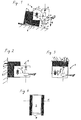
- a self-leveling laser 1 in a compact housing 2 has an electro-optical system 4 automatically aligning itself with gravity G by a pendulum suspension 3 within a self-leveling range ⁇ to produce a perpendicular point-focused visible light beam 5a and a horizontal one sector line-focused, visible light beam 5b in the form of two laser beams.
- a stand 7 is permanently attached to the housing 2 on one side.
- the housing 2 is of the transport position 8, in which the plate-shaped stator 7 covers the housing 2, perpendicular to the light beam 5a, 5b about a limited slidable in a slot in the housing 2, pivot axis A in the angular range ⁇ of about 180 ° swung out pivoted into the use position.
- the lower side surface 9 is exposed and a light beam 5 a emerging through this is visible in a point of impact P on the base 6.
- the construction laser 1 is fastened by means of a fastening means 10 designed as an undercut to a nail in the wall forming the base 6.
- the swung-out angle range ⁇ is about 90 °.
- the construction laser 1 is fastened by means of a fastening means 10 designed as an undercut to a nail in the ceiling forming the base 6.
- the housing 2 is displaced relative to the stand 7 by a distance x, wherein the swung-out angle range ⁇ is about 0 °.
- the plate-shaped stator 7 is arranged with respect to the pivot axis A on both sides of the housing 2 and consists of hard rubber.
Landscapes
- Physics & Mathematics (AREA)
- Engineering & Computer Science (AREA)
- General Physics & Mathematics (AREA)
- Radar, Positioning & Navigation (AREA)
- Remote Sensing (AREA)
- Conveying And Assembling Of Building Elements In Situ (AREA)
Description
- Die Erfindung bezeichnet einen selbstnivellierenden Baulaser zur Erzeugung eines optischen Lotstrahls oder Nivellierstrahls.
- Übliche, sich in einem begrenzten Nivellierbereich von ca. +/- 5° unter dem Einfluss der Schwerkraft, selbstnivellierende Baulaser weisen ein Gehäuse und ein daran reibungsarm drehbar befestigtes selbstnivellierendes elektrooptisches System zur Erzeugung eines senkrechten und/oder waagerechten punktförmigen und/oder linienförmigen sichtbaren Laserstrahls auf.
- Im Unterschied zur Präzisionsvermessungstechnik sind im rauhen Umfeld des Bauhauptgewerbes zubehörfreie, einstückige Baulaser mit kompakten Gehäuseformen und fallbeständigem Stossschutz üblich. Die oftmals bestehende Notwendigkeit der Nutzung des Baulasers auf stark geneigten Unterlagen sowie direkt an Wänden und Decken führt üblicherweise zu provisorischen Hilfskonstruktionen zur Herstellung einer leicht geneigten Unterlage für die Auflagefläche des Baulasers. Ein Stativ sowie Sonderzubehör ist oft nicht unmittelbar verfügbar oder bereits verlorengegangen.
- Nach der US3909952 weist ein optisches Lot, welches auf einer leicht geneigten Unterlage manuell mit Dosenlibellen nivelliert werden muss, eine innerhalb 0-90° drehrastbare Lichtquelle auf. Nach der JP10160471 ist ein kompaktes Seillot für das Baugewerbe temporär an Wänden und Decken befestigbar. Nach der US5012585 weist ein selbstnivellierender Baulaser an dem Gehäuse fest montierte Befestigungsmittel für eine Nutzung des Baulasers auf dem Boden bzw. an der Wand auf. Nach der US5784793 weist ein selbstnivellierender Baulaser ein kompaktes, für das selbstnivellierende elektrooptische System einen Ständer mit einer Auflagefläche ausbildendes, Gehäuse auf. Nach der US5144487 weist die Auflagefläche ein Befestigungsmittel für ein optionales Stativ zur Benutzung auf stark geneigten Unterlagen auf. Zudem ist der auf die Unterlage gerichtete Laserstrahl mittels eines von der Auflagefläche abgesetzten Austrittsfensters frei sichtbar.
- Nach der DE19814151A1 weist ein Rotationsbaulaser zur Erzeugung eines Nivellierstrahls mit einem sich innerhalb eines selbstnivellierenden Nivellierbereiches selbsttätig nach der Schwerkraft ausrichtenden elektrooptischen Systems zur Erzeugung eines rotierenden, optischen Lichtstrahls ein kompaktes Gehäuse auf, an welchem ein Ständer für das Aufsetzen auf eine Unterlage permanent befestigt ist, wobei der Ständer um eine virtuelle Schwenkachse senkrecht zum Lichtstrahl in einem Winkelbereich von ca. 40° stetig drehschwenkbar arretierbar ist.
- Die Aufgabe der Erfindung besteht in der Realisierung eines für das rauhe Umfeld des Bauhauptgewerbes ausgelegten, kompakten Baulasers, welcher auch auf stark geneigten
- Unterlagen sowie direkt an Wänden und Decken nutzbar ist. Ein weiterer Aspekt besteht in der Möglichkeit der einfachen und exakten Positionierung des Baulasers selbst bezüglich einer Markierung auf der Unterlage.
- Die Aufgabe wird im wesentlichen durch die Merkmale der unabhängigen Ansprüche gelöst. Vorteilhafte Weiterbildungen ergeben sich aus den abhängigen Ansprüchen.
- Im wesentlichen weist ein selbstnivellierender Baulaser in einem kompakten Gehäuse ein sich innerhalb eines selbstnivellierenden Nivellierbereiches selbsttätig nach der Schwerkraft ausrichtendes elektrooptisches System zur Erzeugung zumindest eines lotrechten und/oder waagerechten, zumindest in einer Dimension stark fokussierten, sichtbaren Lichtstrahls auf, wobei für das Aufsetzen auf eine Unterlage an dem Gehäuse ein Ständer permanent befestigt ist, welcher um zumindest eine Schwenkachse senkrecht zum Lichtstrahl in einem Winkelbereich von mindestens 180° stetig oder, in vom selbstnivellierenden Nivellierbereich umfassten Winkelschritten, diskret drehschwenkbar arretierbar ist.
- Dabei ist die Schwenkachse vom Mittelpunkt zweier gegenüberliegender Seitenflächen des Gehäuses beabstandet angeordnet, wodurch bezüglich des auf einer Unterlage aufgesetzten Ständers bei einem Herausschwenken des Gehäuses um 180° eine Positionsänderung der Lage der jeweils unteren Seitenfläche gegenüber der Unterlage erzielt wird.
- Durch ein derartiges Herausschwenken des Gehäuses von der Transportstellung in die Nutzungsstellung ist die untere Seitenfläche stets freiliegend und ein durch diese heraustretender Lichtstrahl ist selbst durch seinen sichtbaren Auftreffpunkt auf der Unterlage zur einfachen und exakten Positionierung des Baulasers benutzbar.
- Durch den permanent befestigten drehschwenkbar arretierbaren Ständer ist der Baulaser jederzeit auch auf stark geneigten Unterlagen benutzbar, indem dieser einfach auf den Ständer aufgestellt und über Augenmass bis in den selbstnivellierenden Bereich grob vornivelliert wird.
- Vorteilhaft ist der Winkelbereich grösser als ein Vielfaches von 90° bis einschliesslich zum Vollkreis, wodurch eine temporäre Befestigung an Wänden und Decken über den Ständer möglich ist.
- Vorteilhaft ist die Schwenkachse des Ständers begrenzt verschiebbar im Gehäuse angeordnet, wodurch der Abstand des sichtbaren Auftreffpunktes zur Seitenfläche vergrössert und somit die freie Sichtbarkeit verbessert werden kann.
- Vorteilhaft ist der Ständer reibkraftschlüssig selbsthemmend mit dem Gehäuse verbunden, wodurch eine Arretierung der Vornivellierung technologisch einfach realisiert ist.
- Vorteilhaft ist der Ständer bezüglich der Schwenkachse beidseitig des Gehäuses angeordnet, wodurch der Ständer zugleich einen Schutzrahmen gegen stumpfe Schlagbeanspruchung ausbildet.
- Vorteilhaft ist der Ständer senkrecht zur Schwenkachse einseitig bzw. doppelseitig plattenförmig ausgebildet und deckt weiter vorteilhaft in zumindest einer Schwenkposition das Gehäuse längs der Schwenkachse ab, wodurch der Ständer zugleich eine Schutzplatte gegen spitze Schlagbeanspruchung ausbildet.
- Vorteilhaft ist der Ständer aus einem formstabilen, schlagzähen, energieabsorbierenden Material wie Hartgummi oder Plastikkunststoff gefertigt, wodurch ein aufgenommener Schlag im Material des Ständers dissipiert wird.
- Vorteilhaft weist der Ständer Befestigungsmittel für eine temporäre Montage auf, bspw. Innengewindebuchsen, Durchgangslöcher, Hinterschneidungen.
- Die Erfindung wird bezüglich eines vorteilhaften Ausführungsbeispiels näher erläutert mit:
- Fig. 1 als Baulaser
- Fig. 2 als Befestigungsvariante
- Fig. 3 als Befestigungsvariante
- Fig. 4 als Ständervariante
- Nach Fig. 1 weist ein selbstnivellierender Baulaser 1 in einem kompakten Gehäuse 2 ein sich durch eine Pendelaufhängung 3 innerhalb eines selbstnivellierenden Nivellierbereiches α selbsttätig nach der Schwerkraft G ausrichtendes elektrooptisches System 4 zur Erzeugung eines lotrechten punktförmig fokussierten sichtbaren Lichtstrahls 5a und eines waagerechten, in einem Sektor linienförmig fokussierten, sichtbaren Lichtstrahls 5b in Form zweier Laserstrahlen auf. Für das Aufsetzen auf eine stark geneigte Unterlage 6 ist an dem Gehäuse 2 einseitig ein Ständer 7 permanent befestigt. Das Gehäuse 2 ist von der Transportstellung 8, bei welcher der plattenförmige Ständer 7 das Gehäuse 2 abdeckt, senkrecht zum Lichtstrahl 5a, 5b um eine, in einem Langloch im Gehäuse 2 begrenzt verschiebbare, Schwenkachse A im Winkelbereich β von etwa 180° in die Nutzstellung herausgeschwenkt arretiert. Durch die vom Seitenmittelpunkt des Gehäuses 2 beabstandet angeordnete Schwenkachse A liegt die untere Seitenfläche 9 frei und ein durch diese heraustretender Lichtstrahl 5a ist in einem Auftreffpunkt P auf der Unterlage 6 sichtbar.
- Nach Fig. 2 ist der Baulaser 1 über ein als Hinterschnitt ausgebildetes Befestigungsmittel 10 an einem Nagel in der, die Unterlage 6 bildenden, Wand befestigt. Der herausgeschwenkte Winkelbereich β beträgt etwa 90°.
- Nach Fig. 3 ist der Baulaser 1 über ein als Hinterschnitt ausgebildetes Befestigungsmittel 10 an einem Nagel in der, die Unterlage 6 bildenden, Decke befestigt. Das Gehäuse 2 ist gegenüber dem Ständer 7 um einen Abstand x verschoben, wobei der herausgeschwenkte Winkelbereich β etwa 0° beträgt.
- Nach Fig. 4 ist der plattenförmige Ständer 7 bezüglich der Schwenkachse A beidseitig des Gehäuses 2 angeordnet und besteht aus Hartgummi.
Claims (7)
- Baulaser zur Erzeugung zumindest eines optischen Lotstrahls oder Nivellierstrahls mit einem sich innerhalb eines selbstnivellierenden Nivellierbereiches (α) selbsttätig nach der Schwerkraft (G) ausrichtenden elektrooptischen Systems (4) zur Erzeugung zumindest eines lotrechten und/oder waagerechten, zumindest in einer Dimension stark fokussierten, sichtbaren Lichtstrahls (5a, 5b) und einem kompakten Gehäuse (2), an welchem ein Ständer (7) für das Aufsetzen auf eine Unterlage (6) permanent befestigt ist, welcher um zumindest eine Schwenkachse (A) senkrecht zum Lichtstrahl (5a, 5b) in einem Winkelbereich (β) stetig oder, in vom selbstnivellierenden Nivellierbereich (α) umfassten Winkelschritten, diskret drehschwenkbar arretierbar ist, dadurch gekennzeichnet, dass das Gehäuse (2) in einem Winkelbereich (β) von mindestens 180° um eine im Gehäuse (2) angeordnete Schwenkachse (A) des Ständers (7) herausschwenkbar ist, wobei die Schwenkachse (A) vom Mittelpunkt zweier gegenüberliegender Seitenflächen des Gehäuses (2) beabstandet angeordnet ist.
- Baulaser nach Anspruch 1, dadurch gekennzeichnet, dass die Schwenkachse (A) des Ständers (7) begrenzt verschiebbar im Gehäuse (2) angeordnet ist.
- Baulaser nach einem der vorherigen Ansprüche, dadurch gekennzeichnet, dass der Ständer (7) reibkraftschlüssig selbsthemmend mit dem Gehäuse (2) verbunden ist.
- Baulaser nach einem der vorherigen Ansprüche, dadurch gekennzeichnet, dass der Ständer (7) beidseitig des Gehäuses (2) längs der Schwenkachse (A) angeordnet ist.
- Baulaser nach einem der vorherigen Ansprüche, dadurch gekennzeichnet, dass der Ständer (7) senkrecht zur Schwenkachse (A) einseitig bzw. doppelseitig plattenförmig ausgebildet ist und optional in zumindest einer Schwenkposition das Gehäuse (2) abdeckt.
- Baulaser nach einem der vorherigen Ansprüche, dadurch gekennzeichnet, dass der Ständer (7) aus einem formstabilen, schlagzähen, energieabsorbierenden Material besteht.
- Baulaser nach einem der vorherigen Ansprüche, dadurch gekennzeichnet, dass der Ständer (7) ein Befestigungsmittel (10) für eine temporäre Montage aufweist.
Priority Applications (4)
| Application Number | Priority Date | Filing Date | Title |
|---|---|---|---|
| EP01810947A EP1298413B1 (de) | 2001-09-28 | 2001-09-28 | Selbstnivellierender Baulaser |
| DE50111319T DE50111319D1 (de) | 2001-09-28 | 2001-09-28 | Selbstnivellierender Baulaser |
| US10/243,250 US6754969B2 (en) | 2001-09-28 | 2002-09-12 | Self-leveling constructional laser |
| JP2002286197A JP4237462B2 (ja) | 2001-09-28 | 2002-09-30 | 建設用レーザ装置 |
Applications Claiming Priority (1)
| Application Number | Priority Date | Filing Date | Title |
|---|---|---|---|
| EP01810947A EP1298413B1 (de) | 2001-09-28 | 2001-09-28 | Selbstnivellierender Baulaser |
Publications (2)
| Publication Number | Publication Date |
|---|---|
| EP1298413A1 EP1298413A1 (de) | 2003-04-02 |
| EP1298413B1 true EP1298413B1 (de) | 2006-10-25 |
Family
ID=8184167
Family Applications (1)
| Application Number | Title | Priority Date | Filing Date |
|---|---|---|---|
| EP01810947A Expired - Lifetime EP1298413B1 (de) | 2001-09-28 | 2001-09-28 | Selbstnivellierender Baulaser |
Country Status (4)
| Country | Link |
|---|---|
| US (1) | US6754969B2 (de) |
| EP (1) | EP1298413B1 (de) |
| JP (1) | JP4237462B2 (de) |
| DE (1) | DE50111319D1 (de) |
Families Citing this family (35)
| Publication number | Priority date | Publication date | Assignee | Title |
|---|---|---|---|---|
| US7278218B2 (en) * | 2003-06-18 | 2007-10-09 | Irwin Industrial Tool Company | Laser line generating device with swivel base |
| US7013570B2 (en) * | 2003-06-18 | 2006-03-21 | Irwin-Industrial Tool Company | Stud finder |
| US7269907B2 (en) * | 2003-07-01 | 2007-09-18 | Irwin Industrial Tool Company | Laser line generating device with swivel base |
| US7461613B2 (en) * | 2003-10-23 | 2008-12-09 | Kyp (Holdings) Plc | Device for use as a bookmark or for promotional purposes |
| US7076879B2 (en) * | 2003-11-17 | 2006-07-18 | Kone Corporation | Stabilizer jig for distance measuring laser |
| US7134211B2 (en) | 2004-03-18 | 2006-11-14 | Black & Decker Inc. | Laser level |
| US7487596B2 (en) * | 2004-06-25 | 2009-02-10 | Irwin Industrial Tool Company | Laser line projected on an edge of a surface |
| TW200602624A (en) * | 2004-07-06 | 2006-01-16 | Quarton Inc | Laser light generator with turning functions |
| US7178250B2 (en) * | 2004-07-21 | 2007-02-20 | Irwin Industrial Tool Company | Intersecting laser line generating device |
| US7100293B2 (en) * | 2004-07-28 | 2006-09-05 | Trimble Navigation Limited | Laser alignment tool adapter |
| US7181854B2 (en) * | 2004-08-17 | 2007-02-27 | Eastway Fair Company Limited | Laser leveling device having a suction mounting arrangement |
| US7191532B2 (en) * | 2004-08-17 | 2007-03-20 | Eastway Fair Company Limited | Modular tool assembly having a vacuum mounting arrangement |
| CN100355533C (zh) * | 2005-01-17 | 2007-12-19 | 苏州宝时得电动工具有限公司 | 工具倾斜度确定装置 |
| US7497019B2 (en) * | 2005-08-04 | 2009-03-03 | Irwin Industrial Tool Company | Laser reference device |
| US7328516B2 (en) * | 2005-08-05 | 2008-02-12 | Irwin Industrial Tool Company | Laser level |
| US7243434B1 (en) * | 2006-01-08 | 2007-07-17 | Fred Zucker | Laser theodolite and kit for converting a new or pre-existing theodolite into a laser theodolite |
| DE102006000359A1 (de) * | 2006-07-20 | 2008-01-24 | Hilti Ag | Handhabbarer selbstnivellierender Laserstrahler mit Lotstrahl |
| US20080062669A1 (en) * | 2006-09-07 | 2008-03-13 | Parel Thomas M | Gravity dial level indicator for line generator |
| US20080065348A1 (en) * | 2006-09-11 | 2008-03-13 | Dowd Joseph F | Duct geometry measurement tool |
| US7591075B2 (en) * | 2006-09-28 | 2009-09-22 | Techtronic Power Tools Technology Limited | Self-leveling mechanism |
| DE202007001753U1 (de) * | 2006-12-29 | 2007-06-06 | STABILA Messgeräte Gustav Ullrich GmbH | Messgerät |
| US8209874B1 (en) | 2008-03-13 | 2012-07-03 | Tri-Walker, LLC | Building frame construction tools and methods using laser alignment |
| GB2463259A (en) * | 2008-09-05 | 2010-03-10 | Cathal Leonard | Alignment device |
| EP2938962B1 (de) * | 2012-12-29 | 2018-03-21 | Robert Bosch GmbH | Rotierende lasernivelliervorrichtung mit laserdetektion |
| DE102013217561B4 (de) * | 2013-09-03 | 2017-12-21 | Siemens Healthcare Gmbh | Lokalspule mit Nivellierspiegel |
| WO2016110837A1 (en) * | 2015-01-05 | 2016-07-14 | Kapro Industries Ltd | Laser level with adjustable stand |
| US9433849B1 (en) | 2016-03-02 | 2016-09-06 | Jeb Brown | Method and system for remotely controlling laser light demarcations of ball positions and first downs in a football game |
| US10119817B2 (en) | 2016-04-28 | 2018-11-06 | Stanley Black & Decker Inc. | Laser level |
| US11175136B2 (en) * | 2018-03-09 | 2021-11-16 | Stanley Balck & Decker Inc. | Laser level |
| CN113302450B (zh) | 2019-01-16 | 2023-05-26 | 米沃奇电动工具公司 | 激光投射工具和安装附件 |
| US11385055B2 (en) | 2019-07-23 | 2022-07-12 | Milwaukee Electric Tool Corporation | Laser emitter with a modular storage unit |
| CN122015790A (zh) | 2020-11-02 | 2026-05-12 | 米沃奇电动工具公司 | 激光水平仪对齐工具 |
| WO2022178351A1 (en) | 2021-02-22 | 2022-08-25 | Milwaukee Electric Tool Corporation | Laser level |
| LV15671B (lv) * | 2021-03-09 | 2023-03-20 | Valters Artis | Ierīce, sistēma un metode sienas vai līdzīgas vertikālas virsmas līmeņošanai |
| CN113899351B (zh) * | 2021-11-22 | 2024-03-12 | 山东东汇工程检测鉴定有限公司 | 建筑工程垂直度检测装置及检测方法 |
Family Cites Families (9)
| Publication number | Priority date | Publication date | Assignee | Title |
|---|---|---|---|---|
| US5537205A (en) * | 1994-11-15 | 1996-07-16 | Costa; George J. | Self leveling laser plumb assembly |
| US5539990A (en) * | 1995-05-30 | 1996-07-30 | Le; Mike | Three-dimensional optical levelling, plumbing and angle-calibrating instrument |
| US5621975A (en) * | 1995-08-22 | 1997-04-22 | Levelite Technology | Remotely controlled self-leveling laser instrument with modular capability |
| US5782002A (en) * | 1996-06-03 | 1998-07-21 | Reed; Edwin D. | Laser guidance means |
| US5983510A (en) * | 1997-08-26 | 1999-11-16 | Wu; Chyi-Yiing | Three-dimensional laser levelling and angle-calibrating instrument with multiple functions |
| US5912733A (en) * | 1997-11-05 | 1999-06-15 | Dunlop; Ronald | Laser plumb line |
| DE19814151A1 (de) * | 1998-03-30 | 1999-10-14 | Quante Baulaser Gmbh | Zweiachslasermeßgerät |
| US20020083603A1 (en) * | 2001-01-03 | 2002-07-04 | Jang Jong Shuenn | Infrared pointer holder |
| US6625895B2 (en) * | 2001-12-04 | 2003-09-30 | Toolz, Ltd. | Servo-controlled automatic level and plumb tool |
-
2001
- 2001-09-28 EP EP01810947A patent/EP1298413B1/de not_active Expired - Lifetime
- 2001-09-28 DE DE50111319T patent/DE50111319D1/de not_active Expired - Lifetime
-
2002
- 2002-09-12 US US10/243,250 patent/US6754969B2/en not_active Expired - Lifetime
- 2002-09-30 JP JP2002286197A patent/JP4237462B2/ja not_active Expired - Fee Related
Also Published As
| Publication number | Publication date |
|---|---|
| US20030061720A1 (en) | 2003-04-03 |
| JP4237462B2 (ja) | 2009-03-11 |
| JP2003121152A (ja) | 2003-04-23 |
| US6754969B2 (en) | 2004-06-29 |
| DE50111319D1 (de) | 2006-12-07 |
| EP1298413A1 (de) | 2003-04-02 |
Similar Documents
| Publication | Publication Date | Title |
|---|---|---|
| EP1298413A1 (de) | Selbstnivellierender Baulaser | |
| DE102009002749B3 (de) | Haltevorrichtung zur Befestigung eines Lasergerätes | |
| DE102009002756B3 (de) | Haltevorrichtung zur Befestigung eines Lasergerätes | |
| DE602006000651T2 (de) | Lasernivelliervorrichtung | |
| DE3838512C1 (de) | ||
| US7886450B1 (en) | Elevated laser beam positioning device | |
| WO2009024381A1 (de) | Laservorrichtung und system mit einer laservorrichtung | |
| DE102005000060A1 (de) | Handhabbares Flächenkoordinatenmessgerät | |
| DE19648867A1 (de) | Baulaser | |
| EP2016473A2 (de) | Referenzstrahlgenerator zur erzeugung von leitstrahlen für markierwagen | |
| EP3309510A1 (de) | Höhenverstellbare lasernivelliervorrichtung | |
| US20200131788A1 (en) | Construction jig | |
| KR101619402B1 (ko) | 레이저 레벨기를 삼각대에 거치하기 위한 거치대 | |
| DE202017001724U1 (de) | Universaladapter | |
| US6481111B1 (en) | Spirit level for tile and cabinet installation | |
| DE102004027646A1 (de) | Markierungsgerät | |
| EP2071282B1 (de) | Optomechanisches Nivelliergerät | |
| DE102022003906A1 (de) | Absteckungsanordnung und Verfahren zur Anbringung von Positionsmarkern | |
| DE202008016383U1 (de) | Indirektes Entfernungsmessgerät | |
| LU102766B1 (de) | Befestigungsvorrichtung zur Positionierung eines optischen Mess- und/oder Markierungsinstrumentes | |
| WO2005121704A1 (de) | Vorrichtung zur positionierung von markierungen | |
| DE9100510U1 (de) | Winkelrichtlatte | |
| DE19814149A1 (de) | Zweiachslasermeßgerät | |
| KR102644684B1 (ko) | 현장 적용이 우수한 측지측량용 삼각대 조절장치 | |
| DE102018113622A1 (de) | Haltevorrichtung für ein Lasergerät |
Legal Events
| Date | Code | Title | Description |
|---|---|---|---|
| PUAI | Public reference made under article 153(3) epc to a published international application that has entered the european phase |
Free format text: ORIGINAL CODE: 0009012 |
|
| 17P | Request for examination filed |
Effective date: 20011012 |
|
| AK | Designated contracting states |
Kind code of ref document: A1 Designated state(s): AT BE CH CY DE DK ES FI FR GB GR IE IT LI LU MC NL PT SE TR |
|
| AX | Request for extension of the european patent |
Extension state: AL LT LV MK RO SI |
|
| 17Q | First examination report despatched |
Effective date: 20030707 |
|
| AKX | Designation fees paid |
Designated state(s): DE FR GB IT |
|
| GRAP | Despatch of communication of intention to grant a patent |
Free format text: ORIGINAL CODE: EPIDOSNIGR1 |
|
| GRAS | Grant fee paid |
Free format text: ORIGINAL CODE: EPIDOSNIGR3 |
|
| GRAA | (expected) grant |
Free format text: ORIGINAL CODE: 0009210 |
|
| AK | Designated contracting states |
Kind code of ref document: B1 Designated state(s): DE FR GB IT |
|
| PG25 | Lapsed in a contracting state [announced via postgrant information from national office to epo] |
Ref country code: IT Free format text: LAPSE BECAUSE OF FAILURE TO SUBMIT A TRANSLATION OF THE DESCRIPTION OR TO PAY THE FEE WITHIN THE PRESCRIBED TIME-LIMIT;WARNING: LAPSES OF ITALIAN PATENTS WITH EFFECTIVE DATE BEFORE 2007 MAY HAVE OCCURRED AT ANY TIME BEFORE 2007. THE CORRECT EFFECTIVE DATE MAY BE DIFFERENT FROM THE ONE RECORDED. Effective date: 20061025 |
|
| REG | Reference to a national code |
Ref country code: GB Ref legal event code: FG4D Free format text: NOT ENGLISH |
|
| REF | Corresponds to: |
Ref document number: 50111319 Country of ref document: DE Date of ref document: 20061207 Kind code of ref document: P |
|
| ET | Fr: translation filed | ||
| PLBE | No opposition filed within time limit |
Free format text: ORIGINAL CODE: 0009261 |
|
| STAA | Information on the status of an ep patent application or granted ep patent |
Free format text: STATUS: NO OPPOSITION FILED WITHIN TIME LIMIT |
|
| 26N | No opposition filed |
Effective date: 20070726 |
|
| REG | Reference to a national code |
Ref country code: FR Ref legal event code: PLFP Year of fee payment: 16 |
|
| REG | Reference to a national code |
Ref country code: FR Ref legal event code: PLFP Year of fee payment: 17 |
|
| REG | Reference to a national code |
Ref country code: FR Ref legal event code: PLFP Year of fee payment: 18 |
|
| PGFP | Annual fee paid to national office [announced via postgrant information from national office to epo] |
Ref country code: FR Payment date: 20190925 Year of fee payment: 19 Ref country code: DE Payment date: 20190918 Year of fee payment: 19 |
|
| PGFP | Annual fee paid to national office [announced via postgrant information from national office to epo] |
Ref country code: GB Payment date: 20190920 Year of fee payment: 19 |
|
| PGFP | Annual fee paid to national office [announced via postgrant information from national office to epo] |
Ref country code: IT Payment date: 20200922 Year of fee payment: 20 |
|
| REG | Reference to a national code |
Ref country code: DE Ref legal event code: R119 Ref document number: 50111319 Country of ref document: DE |
|
| GBPC | Gb: european patent ceased through non-payment of renewal fee |
Effective date: 20200928 |
|
| PG25 | Lapsed in a contracting state [announced via postgrant information from national office to epo] |
Ref country code: FR Free format text: LAPSE BECAUSE OF NON-PAYMENT OF DUE FEES Effective date: 20200930 Ref country code: DE Free format text: LAPSE BECAUSE OF NON-PAYMENT OF DUE FEES Effective date: 20210401 |
|
| PG25 | Lapsed in a contracting state [announced via postgrant information from national office to epo] |
Ref country code: GB Free format text: LAPSE BECAUSE OF NON-PAYMENT OF DUE FEES Effective date: 20200928 |