EP1298363B1 - Dispositif de sélection et de changement de vitesses pour une bôite de vitesses - Google Patents
Dispositif de sélection et de changement de vitesses pour une bôite de vitesses Download PDFInfo
- Publication number
- EP1298363B1 EP1298363B1 EP02019003A EP02019003A EP1298363B1 EP 1298363 B1 EP1298363 B1 EP 1298363B1 EP 02019003 A EP02019003 A EP 02019003A EP 02019003 A EP02019003 A EP 02019003A EP 1298363 B1 EP1298363 B1 EP 1298363B1
- Authority
- EP
- European Patent Office
- Prior art keywords
- shift
- select
- coils
- pair
- magnetic
- Prior art date
- Legal status (The legal status is an assumption and is not a legal conclusion. Google has not performed a legal analysis and makes no representation as to the accuracy of the status listed.)
- Expired - Fee Related
Links
Images


Classifications
-
- F—MECHANICAL ENGINEERING; LIGHTING; HEATING; WEAPONS; BLASTING
- F16—ENGINEERING ELEMENTS AND UNITS; GENERAL MEASURES FOR PRODUCING AND MAINTAINING EFFECTIVE FUNCTIONING OF MACHINES OR INSTALLATIONS; THERMAL INSULATION IN GENERAL
- F16H—GEARING
- F16H61/00—Control functions within control units of change-speed- or reversing-gearings for conveying rotary motion ; Control of exclusively fluid gearing, friction gearing, gearings with endless flexible members or other particular types of gearing
- F16H61/26—Generation or transmission of movements for final actuating mechanisms
- F16H61/28—Generation or transmission of movements for final actuating mechanisms with at least one movement of the final actuating mechanism being caused by a non-mechanical force, e.g. power-assisted
- F16H61/32—Electric motors actuators or related electrical control means therefor
-
- F—MECHANICAL ENGINEERING; LIGHTING; HEATING; WEAPONS; BLASTING
- F16—ENGINEERING ELEMENTS AND UNITS; GENERAL MEASURES FOR PRODUCING AND MAINTAINING EFFECTIVE FUNCTIONING OF MACHINES OR INSTALLATIONS; THERMAL INSULATION IN GENERAL
- F16H—GEARING
- F16H61/00—Control functions within control units of change-speed- or reversing-gearings for conveying rotary motion ; Control of exclusively fluid gearing, friction gearing, gearings with endless flexible members or other particular types of gearing
- F16H61/26—Generation or transmission of movements for final actuating mechanisms
- F16H61/28—Generation or transmission of movements for final actuating mechanisms with at least one movement of the final actuating mechanism being caused by a non-mechanical force, e.g. power-assisted
- F16H2061/2853—Electromagnetic solenoids
-
- Y—GENERAL TAGGING OF NEW TECHNOLOGICAL DEVELOPMENTS; GENERAL TAGGING OF CROSS-SECTIONAL TECHNOLOGIES SPANNING OVER SEVERAL SECTIONS OF THE IPC; TECHNICAL SUBJECTS COVERED BY FORMER USPC CROSS-REFERENCE ART COLLECTIONS [XRACs] AND DIGESTS
- Y10—TECHNICAL SUBJECTS COVERED BY FORMER USPC
- Y10T—TECHNICAL SUBJECTS COVERED BY FORMER US CLASSIFICATION
- Y10T74/00—Machine element or mechanism
- Y10T74/19—Gearing
- Y10T74/19219—Interchangeably locked
- Y10T74/19251—Control mechanism
-
- Y—GENERAL TAGGING OF NEW TECHNOLOGICAL DEVELOPMENTS; GENERAL TAGGING OF CROSS-SECTIONAL TECHNOLOGIES SPANNING OVER SEVERAL SECTIONS OF THE IPC; TECHNICAL SUBJECTS COVERED BY FORMER USPC CROSS-REFERENCE ART COLLECTIONS [XRACs] AND DIGESTS
- Y10—TECHNICAL SUBJECTS COVERED BY FORMER USPC
- Y10T—TECHNICAL SUBJECTS COVERED BY FORMER US CLASSIFICATION
- Y10T74/00—Machine element or mechanism
- Y10T74/20—Control lever and linkage systems
- Y10T74/20012—Multiple controlled elements
- Y10T74/20018—Transmission control
- Y10T74/2003—Electrical actuator
-
- Y—GENERAL TAGGING OF NEW TECHNOLOGICAL DEVELOPMENTS; GENERAL TAGGING OF CROSS-SECTIONAL TECHNOLOGIES SPANNING OVER SEVERAL SECTIONS OF THE IPC; TECHNICAL SUBJECTS COVERED BY FORMER USPC CROSS-REFERENCE ART COLLECTIONS [XRACs] AND DIGESTS
- Y10—TECHNICAL SUBJECTS COVERED BY FORMER USPC
- Y10T—TECHNICAL SUBJECTS COVERED BY FORMER US CLASSIFICATION
- Y10T74/00—Machine element or mechanism
- Y10T74/20—Control lever and linkage systems
- Y10T74/20012—Multiple controlled elements
- Y10T74/20018—Transmission control
- Y10T74/20177—Particular element [e.g., shift fork, template, etc.]
Definitions
- the present invention relates to a gear change device for shifting a transmission mounted on a vehicle.
- a gear change device for shifting a transmission comprises a select actuator for actuating a shift lever in a direction of selection and a shift actuator for actuating the shift lever in a direction of shift.
- select actuator and the shift actuator there are generally used fluid pressure cylinders by using a fluid pressure such as air pressure or hydraulic pressure as a source of operation.
- the select actuator and shift actuator employing the fluid cylinders require piping for connecting the source of fluid pressure to each of the actuators, require electromagnetic change-over valves for changing over the flow passage of the operation fluid, and require space for arranging the above components, resulting in an increase in weight of the device as a whole.
- a select actuator and a shift actuator constituted by electric motors as a gear change device for shifting a transmission mounted on a vehicle which is provided with neither a source of compressed air nor a source of hydraulic pressure.
- the select actuator and the shift actuator constituted by electric motors can be constructed in a compact size as a whole and in a reduced weight since they need neither the piping for connection to the source of hydraulic pressure nor the electromagnetic change-over valve, unlike the actuators that use fluid pressure cylinders.
- the actuators using electric motors require a speed reduction mechanism for obtaining a predetermined operation force.
- the speed reduction mechanisms there have been proposed the one using a ball-screw mechanism and the one using a gear mechanism.
- the actuators using the ball-screw mechanism and the gear mechanism are not necessarily satisfactory in regard to durability of the ball screw mechanism and of the gear mechanism and in regard to durability and the operation speed of the electric motors.
- the present applicant therefore, has proposed a gear change device equipped with a select actuator that is excellent in durability and has a high operation speed as Japanese Patent Application No. 2001-013162 .
- the select actuator is constituted by a casing, a control shaft that is rotatably arranged in the casing and is caused to turn by the shift actuator in the direction of shift, a cylindrical shift sleeve that is arranged on the control shaft so as to slide in the axial direction and is constituted integratedly with a shift lever so as to work as a shift lever support member, a magnetic moving means arranged on the outer peripheral surface of the shift sleeve, a cylindrical fixed yoke arranged surrounding the magnetic moving means, and a pair of coils arranged inside the fixed yoke.
- the select actuator must reliably bring the shift lever to a predetermined select position. Therefore, the select actuator in the gear change device is provided with a select position-limiting means for limiting the operation position of the shift sleeve according to the thrust that generates in the shift sleeve as the shift lever support member, in proportion of the amount of electric power fed to the pair of coils.
- the select position-limiting means utilizes a spring force which increases as the shift lever moves in the direction of selection. Therefore, the select actuator produces no sufficient driving force near the select stroke end and often fails to work. To avoid this, the electric power of an increased amount must be supplied to the pair of coils, resulting in a loss of electric power.
- DE 101 02 031 A1 discloses a gear shifting device using two solenoids, which drive iron cores mounted on the movable armature.
- EP 1 225 373 A2 discloses a shift actuator for a transmission, but does not teach to use magnetic members to improve the performance of the shifting.
- EP 1271012 A2 discloses a shift actuator for a transmission that is driven by solenoids and non-permanent magnet cores and is using supportive spring forces.
- an object of the present invention to provide a gear change device equipped with a select actuator which is capable of adding a driving force near the select stroke end.
- a gear change device comprising:
- Said select actuator has a casing, a shift lever support member that is arranged in said casing so as to slide in the axial direction and supports said shift lever.
- Said select actuator has further: a magnetic moving means constituted by an annular permanent magnet which is arranged on the outer periphery of said shift lever support member, a cylindrical fixed yoke arranged surrounding said magnetic moving means, a pair of coils arranged inside said fixed yoke, and a select position-limiting means utilizing spring force for limiting the operation position of said shift lever support member according to a thrust produced by said shift lever support member in proportion to the amount of electric power fed to said pair of coils, and further, magnetic members are arranged on both sides of said pair of coils, so that an attractive force is exerted between said magnetic members and said annular permanent magnet of said magnetic moving means near the stroke end of said shift lever support member.
- the magnetic members can be arranged in a bobbin on which the pair of coils are wound.
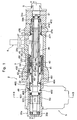
- Fig. 1 is a sectional view illustrating the gear change device constituted according to the present invention
- Fig. 2 is a sectional view along the line A-A in Fig. 1 .
- the gear change device 2 as illustrated is constituted by a select actuator 3 and a shift actuator 5.
- the select actuator 3 has three casings 31a, 31b and 31c formed in a cylindrical shape.
- a control shaft 32 is arranged in the three casings 31a, 31b and 31c. Both ends of the control shaft 32 are rotatably supported by the casings 31a and 31c on both sides through bearings 33a and 33b.
- the control shaft 32 has a spline 321 formed in the middle portion thereof. To the spline 321 is spline-fitted a cylindrical shift sleeve 35 which is integratedly constituted with a shift lever 34 so as to slide in the axial direction.
- the shift sleeve 35 is arranged in the casing so as to slide in the axial direction, and works as a shift lever support member for supporting the shift lever.
- the shift lever 34 and the shift sleeve 35 are made of a nonmagnetic material such as a stainless steel or the like, the shift lever 34 being arranged passing through an opening 311b formed in the lower portion of the central casing 31b.
- An end of the shift lever 34 is so constituted as to come into suitable engagement with the shift blocks 301, 302, 303 and 304 that are arranged at the first select position SP1, at the second select position SP2, at the third select position SP3 and at a fourth select position SP4 and constitute a shift mechanism of a transmission that is not shown.
- a magnetic moving means 36 is arranged on the outer peripheral surface of the shift sleeve 35.
- the magnetic moving means 36 is constituted by an annular permanent magnet 361 mounted on the outer peripheral surface of the shift sleeve 35 and having magnetic poles in both end surfaces in the axial direction and by a pair of moving yokes 362 and 363 arranged on the outer sides of the permanent magnet 361 in the axial direction.
- the permanent magnet 361 can be magnetized into the N-pole in the right end surfaces in Figs. 1 and 2 , and is magnetized into the S-pole in the left end surface in Figs. 1 and 2 .
- the pair of moving yokes 362 and 363 are formed in an annular shape by using a magnetic material.
- the thus constituted magnetic moving means 36 is positioned at its right end in Figs. 1 and 2 of one moving yoke 362 (right side in Figs. 1 and 2 ) by a stepped portion 351 formed in the shift sleeve 35, and is positioned at its left end in Figs. 1 and 2 of the other moving yoke 363 (left side in Figs. 1 and 2 ) by a snap ring 37 fitted to the shift sleeve 35, so that the motion in the axial direction is limited.
- a fixed yoke 39 is arranged on the outer peripheral side of the magnetic moving means 36 to surround the magnetic moving means 36.
- the fixed yoke 39 is formed in a cylindrical shape by using a magnetic material and is mounted on the inner peripheral surface of the central casing 31b.
- a pair of coils 40 and 41 are arranged inside the fixed yoke 39.
- the pair of coils 40 and 41 are wound on a bobbin 42 that is made of a nonmagnetic material such as a synthetic resin or the like and is mounted along the inner peripheral surface of the fixed yoke 39.
- magnetic members 491 and 492 can be arranged in the bobbin 42 on both sides of the pair of coils 40 and 41.
- the magnetic members 491 and 492 are formed in an annular shape by using a magnetic material such as iron or the like.
- the pair of coils 40 and 41 are connected to a power source circuit that is not shown.
- the length of the coil 40 in the axial direction is set to be a length nearly corresponding to the length of selection from the first select position SP1 up to the fourth select position SP4.
- End walls 43 and 44 made of a nonmagnetic material are mounted on both sides of the fixed yoke 39.
- Sealing members 45 and 46 which come in contact with the outer peripheral surfaces of the shift sleeve 35 are mounted on the inner peripheries of the end walls 43 and 44.
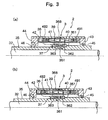
- the select actuator 3 is constituted as described above and operates based on the principle of a linear motor constituted by the magnetic moving means 36 arranged on the shift sleeve 35, the fixed yoke 39 and the pair of coils 40 and 41. The operation will now be described with reference to Fig. 3 .
- the select actuator 3 there is established a magnetic circuit 368 passing through the N-pole of the permanent magnet 361, one moving yoke 362, one coil 40, the fixed yoke 39, the other coil 41, the other moving yoke 363 and S-pole of the permanent magnet 361, as shown in Figs. 3(a) and 3(b) .
- the permanent magnet 361, i.e., the shift sleeve 35 produces a rightward thrust, as indicated by an arrow in Fig. 3(a) according to the Fleming's left-hand rule.
- the select actuator 3 as illustrated can have the first select position-limiting means 47 and the second select position-limiting means 48 for limiting the position of the shift lever 34 to the first select position SP1, to the second select position SP2, to the third select position SP3 or to the fourth select position SP4 in cooperation with the magnitude of thrust acting on the magnetic moving means 36, i.e., on the shift sleeve 35.
- the first select position-limiting means 47 comprises snap rings 471 and 472 mounted on the central casing 31b at the right end portion in Figs.
- a compression coil spring 473 arranged between the snap rings 471 and 472, a moving ring 474 arranged between the compression coil spring 473 and one snap ring 471, and a stopper 475 which limits the motion of the moving ring 474 by coming in contact therewith when the moving ring 474 has moved toward the right by a predetermined amount in Figs. 1 and 2 .
- the magnetic moving means 36 i.e., the shift sleeve 35 moves toward the right in Figs. 1 and 2 , whereby the right end of the shift sleeve 35 comes in contact with the moving ring 474 in Figs. 1 and 2 and is limited for its position.
- the thrust acting on the yoke 36, i.e., on the shift sleeve 35 becomes larger than the resilient force of the coil spring 473.
- the shift sleeve 35 comes in contact with the moving ring 474 and, then, moves toward the right in Figs. 1 and 2 against the resilient force of the coil spring 473, and is brought to a halt at a position at which the moving ring 474 is in contact with the stopper 475.
- the shift lever 34 constituted integratedly with the shift sleeve 35 is brought to the first select position SP1.
- the second select position-limiting means 48 comprises snap rings 481 and 482 mounted on the central casing 31b at the left end in Figs. 1 and 2 at a predetermined distance, a coil spring 483 arranged between the snap rings 481 and 482, a moving ring 484 arranged between the coil spring 483 and one snap ring 481, and a stopper 485 which limits the motion of the moving ring 484 by coming in contact therewith when the moving ring 484 has moved toward the left by a predetermined amount in Figs. 1 and 2 .
- the magnetic moving means 36 i.e., the shift sleeve 35 moves toward the left in Figs. 1 and 2 , whereby the left end of the shift sleeve 35 comes in contact with the moving ring 484 in Figs. 1 and 2 and is limited for its position.
- the thrust acting on the magnetic moving means 36, i.e., on the shift sleeve 35 becomes larger than the resilient force of the coil spring 483.
- the shift sleeve 35 comes in contact with the moving ring 484 and, then, moves toward the left in Figs. 1 and 2 against the resilient force of the coil spring 483, and is brought to a halt at a position at which the moving ring 484 is in contact with the stopper 485.
- the shift lever 34 constituted integratedly with the shift sleeve 35 is brought to the fourth select position SP4.
- the device is provided with the first select position-limiting means 47 and the second select position-limiting means 48.
- the shift lever 34 can be brought to a desired select position without the need of controlling the position.
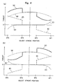
- Fig. 4(a) illustrates the driving force of the select actuator 3 of when the magnetic moving means 36, i.e., the shift sleeve 35 is operated toward the right
- Fig. 4(b) illustrates the driving force of the select actuator 3 of when the magnetic moving means 36, i.e., the shift sleeve 35 is operated toward the left.
- Figs. 4(a) illustrates the driving force of the select actuator 3 of when the magnetic moving means 36, i.e., the shift sleeve 35 is operated toward the right
- Fig. 4(b) illustrates the driving force of the select actuator 3 of when the magnetic moving means 36, i.e., the shift sleeve 35 is operated toward the left.
- broken lines (B) represent thrust characteristics based on the principle of a linear motor constituted by the magnetic moving means 36, the fixed yoke 39 and the pair of coils 40 and 41
- chain lines (C) represent attractive forces between the permanent magnet 361 and the magnetic member 491
- chain lines (D) represent attractive forces between the permanent magnet 361 and the magnetic member 492
- two-dot chain lines (E) represent thrust characteristics of the coil spring 473 of the first select position-limiting means 47
- two-dot chain lines (F) represent thrust characteristics of the coil spring 483 of the second select position-limiting means 48
- solid lines (A) represent driving forces of the select actuator 3 of when an electric current is fed to the pair of coils 40 and 41.
- the driving force of the select actuator 3 of when an electric current is fed to the pair of coils 40 and 41 represented by the solid line (A) is a synthesis of the thrust represented by the broken line (B) produced based on the principle of the linear motor constituted by the magnetic moving means 36, the fixed yoke 39 and the pair of coils 40 and 41, attractive forces represented by the chain lines (C) and (D) between the permanent magnet 361 and the magnetic members 491, 492, and the thrusts of the coil springs 473 and 483 represented by the two-dot chain lines (E) and (F).
- the thrust characteristics represented by the broken lines (B) based on the principle of the linear motor constituted by the magnetic moving means 36, the fixed yoke 39 and the pair of coils 40 and 41 are those of when a voltage of, for example, 4.8 V is applied to the pair of coils 40 and 41.
- the thrust of when a voltage of, for example, 2.4 V is applied to the pair of coils 40 and 41 is set to be smaller than the thrusts of the coil spring 473 of the first select position-limiting means 47 and of the coil spring 483 of the second select position-limiting means 48 at the second select position SP2 and at the third select position SP3.
- the attractive force between the permanent magnet 361 and the magnetic member 492 acts as a negative (-) force as represented by the chain line (D)
- the attractive force between the permanent magnet 361 and the magnetic member 491 acts as a positive (+) force as represented by the chain line (C).
- the thrust of the coil spring 483 of the second select position-limiting means 48 acts as a positive (+) force as represented by the two-dot chain line (F), and the thrust of the coil spring 473 of the first select position-limiting means 47 acts as a negative (-) force as represented by the two-dot chain line (E).
- the thrust of the coil spring 483 of the second select position-limiting means 48 acts as the positive (+) force, and the select actuator 3 produces a sufficiently large driving force.
- the attractive force between the permanent magnet 361 and the magnetic member 491 acts as a positive (+) force as represented by the chain line (C) near the first select position SP1, i.e., near the select stroke end.
- the magnetic moving means 36 i.e., the shift sleeve 35 is moved toward the right as shown in Fig. 4(a) , therefore, the select actuator 3 has a driving force (A) which is large enough even at the first select position SP1 which is the select stroke end.
- the attractive force between the permanent magnet 361 and the magnetic member 491 acts as a negative (-) force as represented by the chain line (C)
- the attractive force between the permanent magnet 361 and the magnetic member 492 acts as a positive (+) force as represented by the chain line (D).
- the thrust of the coil spring 473 of the first select position-limiting means 47 acts as a positive (+) force as represented by the two-dot chain line (E), and the thrust of the coil spring 483 of the second select position-limiting means 48 acts as a negative (-) force as represented by the two-dot chain line (F).
- the thrust of the coil spring 473 of the first select position-limiting means 47 acts as the positive (+) force, and the select actuator 3 produces a sufficiently large driving force.
- the attractive force between the permanent magnet 361 and the magnetic member 491 acts as a positive (+) force as represented by the chain line (D) near the fourth select position SP4, i.e., near the select stroke end.
- the magnetic moving means 36 i.e., the shift sleeve 35 is moved toward the left as shown in Fig. 4(b) , therefore, the select actuator 3 has a driving force (A) which is large enough even at the fourth select position SP4 which is the select stroke end.
- the gear change device has a select position sensor 8 for detecting the position of the shift sleeve 35 integratedly constituted with the shift lever 34, i.e., for detecting the position thereof in the direction of selection.
- the select position sensor 8 comprises a potentiometer, and one end portion of a lever 82 is attached to a turning shaft 81 thereof.
- An engaging pin 83 attached to the other end portion of the lever 82 is engaged with an engaging groove 352 formed in the shift sleeve 35. Therefore, when the shift sleeve 35 moves toward the right or left in Fig.
- the lever 82 swings on the turning shaft 81, whereby the turning shaft 81 turns and the operation position of the shift sleeve 35 is detected, i.e., the position thereof in the direction of selection is detected.
- the shift lever 34 can be brought to a desired select position by controlling the voltage and the direction of current fed to the coils 40 and 41 of the select actuator 3 by a controller (not shown), based on a signal from the select position sensor 8.
- the gear change device 2 has a shift stroke position sensor 9 for detecting a turning position of the control shaft 32 mounting the shift sleeve 35 which is integratedly constituted with the shift lever 34, i.e., for detecting the shift stroke position thereof.
- the shift stroke position sensor 9 comprises a potentiometer, and its turning shaft 91 is coupled to the control shaft 32. When the control shaft 32 turns, therefore, the turning shaft 91 turns and the turning position of the control shaft 32, i.e., the shift stroke position thereof is detected.
- the shift sleeve 35 which is a shift lever support member for supporting the shift lever 34 is mounted on the control shaft 32 so as to slide in the axial direction.
- the control shaft 32 is arranged in the casing so as to slide in the axial direction, and works as a shift lever support member for supporting the shift lever.
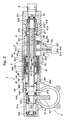
- Fig. 5 is a sectional view along the line B-B in Fig. 1 .
- the shift actuator 5 shown in Fig. 5 has a casing 51, an operation rod 52 that is arranged in the central portion of the casing 51 and engages with the operation lever 50 mounted on the control shaft 32 arranged in the casings 31a, 31b and 31c of the select actuator 3, a magnetic moving means 53 arranged on the outer peripheral surface of the operation rod 52, a cylindrical fixed yoke 54 surrounding the magnetic moving means 53 and arranged inside the casing 51, and a pair of coils 55 and 56 arranged side by side in the axial direction inside the fixed yoke 54.
- the operation lever 50 that engages with the operation rod 52 has a hole 501 in the base portion thereof to be fitted to the control shaft 32, and turns integratedly with the control shaft 32 by fitting a key 503 into a keyway 502 formed in the inner peripheral surface of the hole 501 and into a keyway 322 formed in the outer peripheral surface of the control shaft 32.
- the operation lever 50 works as an operation member coupled to the shift lever 34 via the control shaft 32 and the shift sleeve 35, and is arranged passing through an opening 311a formed in the lower portion of the left casing 31a in Figs. 1 and 2 .
- the casing 51 is formed in a cylindrical shape by using a nonmagnetic material such as a stainless steel, an aluminum alloy or the like.
- the operation rod 52 is constituted by using a nonmagnetic material such as a stainless steel or the like, and has a notch 521 formed in the left end thereof in Fig. 5 . An end of the operation lever 50 is brought into engagement with the notch 521.
- the magnetic moving means 53 is constituted by an annular permanent magnet 531 mounted on the outer peripheral surface of the operation rod 52 and having magnetic poles in both end surfaces thereof in the axial direction and by a pair of moving yokes 532 and 533 arranged on the outer sides of the permanent magnet 531 in the axial direction.
- the permanent magnet 531 can be magnetized into the N-pole in the right end surface in Fig. 5 and can be magnetized into the S-pole in the left end surface in Fig. 5 .
- the pair of moving yokes 532 and 533 are formed in an annular shape by using a magnetic material.
- the thus constituted magnetic moving means 53 is positioned by snap rings 534 and 535 mounted on the operation rod 52 on both sides of the magnetic moving means 53, and is limited from moving in the axial direction.
- the fixed yoke 54 is formed in a cylindrical shape by using a magnetic material and is mounted on the inner peripheral surface of the casing 51.
- a pair of coils 55 and 56 are arranged inside the fixed yoke 54.
- the pair of coils 55 and 56 are wound on a bobbin 57 that is made of a nonmagnetic material such as a synthetic resin or the like and is mounted on the inner periphery of the fixed yoke 54.
- the pair of coils 55 and 56 are connected to a power source circuit that is not shown.
- magnetic members 581 and 582 are arranged in the bobbin 57 on both sides of the pair of coils 55 and 56.
- the magnetic members 581 and 582 are formed in an annular shape by using a magnetic material such as iron or the like.
- the length of the pair of coils 55 and 56 in the axial direction is suitably set depending on the operation stroke of the shift actuator 5.
- End walls 61 and 62 are each mounted on both sides of the casing 51.
- the end walls 61 and 62 are made of a nonmagnetic material such as a stainless steel, an aluminum alloy or a suitable synthetic resin, and have holes 611 and 621 formed in the central portions thereof, so that a shift plunger 52 is inserted therein.
- the operation rod 52 arranged being inserted in the holes 611 and 621 is supported by the inner peripheral surfaces of the holes 611 and 621 so as to slide in the axial direction.
- Notches 612 and 622 are formed in the end walls 61 and 62 in the inner peripheral portions on the outer sides thereof. Sealing members 63 and 64 are fitted into the notches 612 and 622.
- the shift actuator 5 is constituted as described above, and its operation will now be described with reference to Fig. 6 .
- the shift actuator 5 is constituted as described above, and operates based on the principle of a linear motor constituted by the magnetic moving means 53 arranged on the operation rod 52, the fixed yoke 54 and the pair of coils 55 and 56. The operation will now be described with reference to Fig. 6 .
- the controller so judges that it has operated up to one shift stroke end, i.e., up to the gear-engaging position based on a signal from the shift stroke position sensor 9, and interrupts the flow of current to the pair of coils 55 and 56.
- the shift lever 34 constituted integratedly with the shift sleeve 35 which is mounted on the control shaft 32 is shifted in the other direction.
- the controller (not shown) so judges that it has operated up to the other shift stroke end, i.e., up to the gear-engaging position based on a signal from the shift stroke position sensor 9, and interrupts the flow of current to the pair of coils 55 and 56.
- Fig. 7(a) illustrates the driving force of the shift actuator 5 of when the magnetic moving means 53, i.e., the operation rod 52 is operated toward the left
- Fig. 7(b) illustrates the driving force of the shift actuator 5 of when the magnetic moving means 53, i.e., the operation rod 52 is operated toward the right.
- Figs. 7(a) illustrates the driving force of the shift actuator 5 of when the magnetic moving means 53, i.e., the operation rod 52 is operated toward the left
- Fig. 7(b) illustrates the driving force of the shift actuator 5 of when the magnetic moving means 53, i.e., the operation rod 52 is operated toward the right.
- broken lines (B) represent thrust characteristics based on the principle of a linear motor constituted by the magnetic moving means 53, the fixed yoke 54 and the pair of coils 55 and 56
- chain lines (C) represent attractive forces between the permanent magnet 531 and the magnetic member 581
- chain lines (D) represent attractive forces between the permanent magnet 531 and the magnetic member 382
- solid lines (A) represent driving forces of the select actuator 5 of when an electric current is fed to the pair of coils 55 and 56.
- the driving force of the shift actuator 5 of when an electric current is fed to the pair of coils 55 and 56 represented by the solid line (A) is a synthesis of the thrust represented by the broken line (B) produced based on the principle of the linear motor constituted by the magnetic moving means 53, the fixed yoke 54 and the pair of coils 55 and 56, and attractive forces represented by the chain lines (C) and (D) between the permanent magnet 531 and the magnetic members 581, 582.
- the pair of magnetic members 581 and 582 are arranged on both sides of the pair of coils 55 and 56.
- the shifting mechanism of the transmission is equipped with a detent mechanism for holding a state in which the shift lever has been shifted to the shift stroke end, i.e., the gear-engaged state, in order to prevent the gear from undesirably disengaging.
- the attractive force between the permanent magnet 531 and the magnetic member 581 or 582 can work as the detent mechanism near the shift stroke end.
- the gear change device according to the present invention exhibits actions and effects as described below.
- the select actuator constituting the gear change device has a casing, a shift lever support member that is arranged in the casing so as to slide in the axial direction and supports the shift lever, a magnetic moving means arranged on the outer periphery of the shift lever support member, a cylindrical fixed yoke arranged surrounding the magnetic moving means, a pair of coils arranged inside the fixed yoke, and a select position-limiting means for limiting the operation position of the shift lever support member according to a thrust produced by the shift lever support member in proportion to the amount of electric power fed to the pair of coils; and further magnetic members are arranged on both sides of the pair of coils. Accordingly, the attractive force acts between the magnetic moving means and the magnetic member near the select stroke end with the consequence that a sufficiently large driving force is produced even near the select stroke end.
Claims (2)
- Dispositif de changement de vitesses (2) comprenant :un actionneur de sélection (3) permettant de commander le levier de vitesses (34) d'une transmission dans la direction de sélection ; etun actionneur de changement de vitesses (5) permettant de commander ledit levier de vitesses (34) dans la direction de changement de vitesses ;
dans lequelledit actionneur de sélection (3) comporte un carter (31a, 31b, 31c), etun élément de support de levier de vitesses (35) qui est disposé dans ledit carter (31a, 31b, 31c) de manière à coulisser dans la direction axiale et supporte ledit levier de vitesses (34),caractérisé en ce que
ledit actionneur de sélection (3) comporte en outre :un moyen de déplacement magnétique (36) muni d'un aimant permanent annulaire (361) qui est disposé sur la périphérie externe dudit élément de support de levier de vitesses (35),une culasse fixe cylindrique (39) disposée autour dudit moyen de déplacement magnétique (36),une paire d'enroulements (40, 41) disposée à l'intérieur de ladite culasse fixe (39),et un moyen de limitation de la position de sélection (47, 48) est fourni et utilise une force de ressort pour limiter la position de fonctionnement dudit élément de support de levier de vitesses (35) en fonction d'une poussée produite par ledit élément de support de levier de vitesses (35) proportionnellement à la quantité d'énergie électrique fournie à ladite paire d'enroulements (40, 41) et en outre, des éléments magnétiques (491, 492) sont disposés sur les deux côtés de ladite paire d'enroulements (40, 41), de sorte qu'une force d'attraction s'exerce entre lesdits éléments magnétiques (491, 492) et ledit aimant permanent annulaire (361) dudit moyen de déplacement magnétique (36) près de la fin de course dudit élément de support de levier de vitesses (35). - Dispositif de changement de vitesses (2) selon la revendication 1, dans lequel lesdits éléments magnétiques (491, 492) sont disposés dans une bobine (42) sur laquelle ladite paire d'enroulements (40, 41) est enroulée.
Applications Claiming Priority (2)
| Application Number | Priority Date | Filing Date | Title |
|---|---|---|---|
| JP2001300831 | 2001-09-28 | ||
| JP2001300831A JP4756303B2 (ja) | 2001-09-28 | 2001-09-28 | 変速操作装置 |
Publications (3)
| Publication Number | Publication Date |
|---|---|
| EP1298363A2 EP1298363A2 (fr) | 2003-04-02 |
| EP1298363A3 EP1298363A3 (fr) | 2007-08-01 |
| EP1298363B1 true EP1298363B1 (fr) | 2009-05-20 |
Family
ID=19121344
Family Applications (1)
| Application Number | Title | Priority Date | Filing Date |
|---|---|---|---|
| EP02019003A Expired - Fee Related EP1298363B1 (fr) | 2001-09-28 | 2002-08-26 | Dispositif de sélection et de changement de vitesses pour une bôite de vitesses |
Country Status (4)
| Country | Link |
|---|---|
| US (1) | US6732607B2 (fr) |
| EP (1) | EP1298363B1 (fr) |
| JP (1) | JP4756303B2 (fr) |
| DE (1) | DE60232394D1 (fr) |
Families Citing this family (15)
| Publication number | Priority date | Publication date | Assignee | Title |
|---|---|---|---|---|
| US6892601B2 (en) * | 2001-06-29 | 2005-05-17 | Isuzu Motors Limited | Gear change device |
| JP4279534B2 (ja) * | 2002-10-04 | 2009-06-17 | いすゞ自動車株式会社 | 電磁ソレノイドおよびこれを用いた変速機のシフトアクチュエータ |
| DE102004007295B3 (de) * | 2004-02-14 | 2005-09-29 | Dr.Ing.H.C. F. Porsche Ag | Vorrichtung und Verfahren zur Simulation einer manuellen Bedieneinrichtung |
| DE102004052804B3 (de) * | 2004-10-26 | 2006-01-19 | Getrag Getriebe-Und Zahnradfabrik Hermann Hagenmeyer Gmbh & Cie Kg | Schalteinrichtung |
| DE102005011280A1 (de) * | 2005-03-11 | 2006-09-28 | Zf Friedrichshafen Ag | Wählschieber, insbesondere Wählschieber des hydraulischen Steuersystems des Getriebes eines Kraftfahrzeugs |
| WO2006114444A1 (fr) * | 2005-04-28 | 2006-11-02 | Deere & Company | Dispositif pour actionner un point de changement de vitesse d'une boite de vitesses |
| DE102005027299B4 (de) | 2005-04-28 | 2022-04-28 | Deere & Company | Vorrichtung zur Betätigung einer Getriebeschaltstelle |
| DE102005040633A1 (de) | 2005-08-27 | 2007-03-29 | Deere & Company, Moline | Getriebeschaltstelle zum Herstellen einer drehfesten Verbindung zwischen einem Zahnrad und einer Welle |
| US20070210653A1 (en) * | 2006-03-13 | 2007-09-13 | Scanlon Matthew J | Moving magnet actuator with counter-cogging end-ring and asymmetrical armature stroke |
| DE102006030793A1 (de) * | 2006-06-30 | 2008-01-03 | Zf Friedrichshafen Ag | Schalteinrichtung für ein Schaltgetriebe |
| KR100891514B1 (ko) | 2007-12-24 | 2009-04-06 | 다이모스(주) | 수동변속기의 쉬프트장치 |
| ITTO20080034A1 (it) * | 2008-01-16 | 2009-07-17 | Automac Di Bigi Ing Maurizio Sas | Dispositivo di comando per l'innesto delle marce per un cambio di velocita' di un veicolo con tamburo rotante presentante una camma principale e una camma ausiliaria |
| CN202834027U (zh) * | 2012-09-27 | 2013-03-27 | 陕西法士特齿轮有限责任公司 | 一种变速器操纵机构 |
| CN106246905A (zh) * | 2016-08-31 | 2016-12-21 | 西安法士特汽车传动有限公司 | 一种四个档位的自动操纵装置 |
| CN110576706B (zh) * | 2018-06-08 | 2021-10-12 | 郑州宇通客车股份有限公司 | 车辆运动状态控制方法及车辆 |
Family Cites Families (18)
| Publication number | Priority date | Publication date | Assignee | Title |
|---|---|---|---|---|
| JPS56113251U (fr) * | 1980-01-31 | 1981-09-01 | ||
| JPH0235172B2 (ja) * | 1982-05-06 | 1990-08-08 | Isuzu Jidosha Kk | Hensokukikudosochi |
| JPS5940048A (ja) | 1982-08-31 | 1984-03-05 | Fuji Heavy Ind Ltd | オ−トクラツチ車の変速操作機構 |
| JPS6469878A (en) | 1987-09-10 | 1989-03-15 | Diesel Kiki Co | Solenoid proportional pressure control valve |
| US5241292A (en) | 1992-05-28 | 1993-08-31 | Prime Mover, Inc. | Three position electrically operated actuator |
| WO1993026026A1 (fr) | 1992-06-12 | 1993-12-23 | Oki Electric Industry Co., Ltd. | Capteur de chocs |
| JP2595510Y2 (ja) * | 1992-11-12 | 1999-05-31 | ティーディーケイ株式会社 | 可動磁石式アクチュエータ |
| US5191804A (en) | 1992-07-23 | 1993-03-09 | Eaton Corporation | Dual force fluid actuated shift device |
| GB9225890D0 (en) | 1992-12-11 | 1993-02-03 | Eaton Corp | Downshift inhibitor |
| DE19527893C1 (de) | 1995-07-29 | 1996-10-31 | Ford Werke Ag | Elektrische Schaltvorrichtung für Wechselgetriebe von Kraftfahrzeugen |
| US5743143A (en) | 1996-08-09 | 1998-04-28 | Eaton Corporation | Transmission shifting mechanism and position sensor |
| JPH10213221A (ja) * | 1997-01-28 | 1998-08-11 | Suzuki Motor Corp | 変速操作装置 |
| DE19842532A1 (de) * | 1998-09-17 | 1999-09-30 | Bosch Gmbh Robert | Schaltvorrichtung |
| IT1311099B1 (it) | 1999-10-18 | 2002-02-28 | Magneti Marelli Spa | Gruppo di comando dell'albero di selezione ed innesto delle marce diun cambio di velocita'. |
| GB0005185D0 (en) * | 2000-03-04 | 2000-04-26 | Luk Lamellen & Kupplungsbau | Gear engagement mechanisms |
| JP2003529024A (ja) | 2000-03-28 | 2003-09-30 | ルーク ラメレン ウント クツプルングスバウ ベタイリグングス コマンディートゲゼルシャフト | 変速機を備えた自動車 |
| JP4224945B2 (ja) * | 2001-01-22 | 2009-02-18 | いすゞ自動車株式会社 | 変速機のシフトアクチュエータ |
| US6892601B2 (en) * | 2001-06-29 | 2005-05-17 | Isuzu Motors Limited | Gear change device |
-
2001
- 2001-09-28 JP JP2001300831A patent/JP4756303B2/ja not_active Expired - Fee Related
-
2002
- 2002-08-14 US US10/217,431 patent/US6732607B2/en not_active Expired - Lifetime
- 2002-08-26 EP EP02019003A patent/EP1298363B1/fr not_active Expired - Fee Related
- 2002-08-26 DE DE60232394T patent/DE60232394D1/de not_active Expired - Lifetime
Also Published As
| Publication number | Publication date |
|---|---|
| US20030061895A1 (en) | 2003-04-03 |
| US6732607B2 (en) | 2004-05-11 |
| DE60232394D1 (fr) | 2009-07-02 |
| EP1298363A2 (fr) | 2003-04-02 |
| EP1298363A3 (fr) | 2007-08-01 |
| JP2003106446A (ja) | 2003-04-09 |
| JP4756303B2 (ja) | 2011-08-24 |
Similar Documents
| Publication | Publication Date | Title |
|---|---|---|
| EP1298362B1 (fr) | Dispositif de commande pour boîte de vitesses | |
| EP1406033B1 (fr) | Solénoide électromagnétique et actionneur de boite de vitesses l'utilisant | |
| EP1298363B1 (fr) | Dispositif de sélection et de changement de vitesses pour une bôite de vitesses | |
| US6634249B2 (en) | Shift actuator for a transmission | |
| EP1271011B1 (fr) | Dispositif de changement de vitesses | |
| US7100470B2 (en) | Gear change device | |
| US6848330B2 (en) | Gear change device | |
| US6889573B2 (en) | Shift actuator for a transmission | |
| US6880422B2 (en) | Shift actuator for a transmission | |
| JP3687586B2 (ja) | 変速機のシフトアクチュエータ | |
| JP3893957B2 (ja) | 変速操作装置 |
Legal Events
| Date | Code | Title | Description |
|---|---|---|---|
| PUAI | Public reference made under article 153(3) epc to a published international application that has entered the european phase |
Free format text: ORIGINAL CODE: 0009012 |
|
| AK | Designated contracting states |
Kind code of ref document: A2 Designated state(s): AT BE BG CH CY CZ DE DK EE ES FI FR GB GR IE IT LI LU MC NL PT SE SK TR |
|
| AX | Request for extension of the european patent |
Extension state: AL LT LV MK RO SI |
|
| PUAL | Search report despatched |
Free format text: ORIGINAL CODE: 0009013 |
|
| AK | Designated contracting states |
Kind code of ref document: A3 Designated state(s): AT BE BG CH CY CZ DE DK EE ES FI FR GB GR IE IT LI LU MC NL PT SE SK TR |
|
| AX | Request for extension of the european patent |
Extension state: AL LT LV MK RO SI |
|
| 17P | Request for examination filed |
Effective date: 20080201 |
|
| AKX | Designation fees paid |
Designated state(s): DE FR GB |
|
| 17Q | First examination report despatched |
Effective date: 20080313 |
|
| GRAP | Despatch of communication of intention to grant a patent |
Free format text: ORIGINAL CODE: EPIDOSNIGR1 |
|
| GRAS | Grant fee paid |
Free format text: ORIGINAL CODE: EPIDOSNIGR3 |
|
| GRAA | (expected) grant |
Free format text: ORIGINAL CODE: 0009210 |
|
| AK | Designated contracting states |
Kind code of ref document: B1 Designated state(s): DE FR GB |
|
| REG | Reference to a national code |
Ref country code: GB Ref legal event code: FG4D |
|
| REF | Corresponds to: |
Ref document number: 60232394 Country of ref document: DE Date of ref document: 20090702 Kind code of ref document: P |
|
| PLBE | No opposition filed within time limit |
Free format text: ORIGINAL CODE: 0009261 |
|
| STAA | Information on the status of an ep patent application or granted ep patent |
Free format text: STATUS: NO OPPOSITION FILED WITHIN TIME LIMIT |
|
| 26N | No opposition filed |
Effective date: 20100223 |
|
| REG | Reference to a national code |
Ref country code: FR Ref legal event code: PLFP Year of fee payment: 15 |
|
| PGFP | Annual fee paid to national office [announced via postgrant information from national office to epo] |
Ref country code: DE Payment date: 20160823 Year of fee payment: 15 Ref country code: GB Payment date: 20160824 Year of fee payment: 15 |
|
| PGFP | Annual fee paid to national office [announced via postgrant information from national office to epo] |
Ref country code: FR Payment date: 20160712 Year of fee payment: 15 |
|
| REG | Reference to a national code |
Ref country code: DE Ref legal event code: R119 Ref document number: 60232394 Country of ref document: DE |
|
| GBPC | Gb: european patent ceased through non-payment of renewal fee |
Effective date: 20170826 |
|
| REG | Reference to a national code |
Ref country code: FR Ref legal event code: ST Effective date: 20180430 |
|
| PG25 | Lapsed in a contracting state [announced via postgrant information from national office to epo] |
Ref country code: DE Free format text: LAPSE BECAUSE OF NON-PAYMENT OF DUE FEES Effective date: 20180301 Ref country code: GB Free format text: LAPSE BECAUSE OF NON-PAYMENT OF DUE FEES Effective date: 20170826 |
|
| PG25 | Lapsed in a contracting state [announced via postgrant information from national office to epo] |
Ref country code: FR Free format text: LAPSE BECAUSE OF NON-PAYMENT OF DUE FEES Effective date: 20170831 |